Embed Size (px)
Citation preview

ENERGY STAR® Program Requirements
for Imaging Equipment
Partner Commitments
Following are the terms of the ENERGY STAR Partnership Agreement as it pertains to the manufacture and labeling of ENERGY STAR qualified products. The ENERGY STAR Partner must adhere to the following partner commitments:
Qualifying Products
1. Comply with current ENERGY STAR Eligibility Criteria, which define performance requirements and test procedures for Imaging Equipment. A list of eligible products and their corresponding Eligibility Criteria can be found at www.energystar.gov/specifications.
2. Prior to associating the ENERGY STAR name or mark with any product, obtain written certification of ENERGY STAR qualification from a Certification Body recognized by EPA for Imaging Equipment. As part of this certification process, products must be tested in a laboratory recognized by EPA to perform Imaging Equipment testing. A list of EPA-recognized laboratories and certification bodies can be found at www.energystar.gov/testingandverification.
3. Ensure that any model associated with the ENERGY STAR name or mark meets the following standards:
3.1. Product material requirements as defined in restriction of hazardous substances (RoHS) regulations, as generally accepted. This includes exemptions in force at the date of product manufacture, where the maximum concentration values tolerated by weight in homogeneous materials are: lead (0.1%), mercury (0.1%), cadmium (0.01%), hexavalent chromium (0.1%), polybrominated biphenyls (PBB) (0.1%), or polybrominated diphenyl ethers (PBDE) (0.1%). Batteries are exempt.
3.2. The generally accepted attributes of a recyclable product at the date of product manufacture: where products shall be designed for ease of disassembly and recyclability where external enclosures, sub-enclosures, chassis and electronic subassemblies are easily removable by hand with commonly available tools.
Notes: • The explicit intention is to harmonize with EU RoHS and Section 4.3.1.1 of IEEE 1680.2-2012 Standard for Environmental
Assessment of Imaging Equipment.
• For purposes of ENERGY STAR third-party certification, these requirements shall not be reviewed when products are initially qualified nor during subsequent verification testing. Rather, EPA reserves the right to request supporting documentation at any time.
Using the ENERGY STAR Name and Marks
4. Comply with current ENERGY STAR Identity Guidelines, which define how the ENERGY STAR name and marks may be used. Partner is responsible for adhering to these guidelines and ensuring that its authorized representatives, such as advertising agencies, dealers, and distributors, are also in compliance. The ENERGY STAR Identity Guidelines are available at www.energystar.gov/logouse.
5. Use the ENERGY STAR name and marks only in association with qualified products. Partner may not refer to itself as an ENERGY STAR Partner unless at least one product is qualified and offered for sale in the U.S and/or ENERGY STAR partner countries.
6. Provide clear and consistent labeling of ENERGY STAR qualified Imaging Equipment.
6.1. The ENERGY STAR mark must be clearly displayed:
ENERGY STAR Program Requirements for Imaging Equipment – Partner Commitments Page 1 of 3

6.1.1. Either on the top/front of product or through electronic messaging that is pre-approved by EPA. Labeling on the top/front of product may be permanent or temporary. All temporary labeling must be affixed to the top/front of product with an adhesive or cling-type application;
6.1.2. On the manufacturer’s Internet site where information about ENERGY STAR qualified models is displayed. Specific guidance on using the ENERGY STAR mark on Internet sites is provided in the Web-Based Tools for Partners document;
6.1.3. Either in product literature (e.g., user manuals, specification sheets, etc.) or in a separate box insert that provides educational language about the product’s ENERGY STAR settings; and
6.1.4. On product packaging/boxes for products sold at retail.
6.2. If additional information about the ENERGY STAR program(s) or other products provided by the Partner on its Web site, Partner must comply with the ENERGY STAR Web Linking Policy, which can be found at www.energystar.gov/partners.
Verifying Ongoing Product Qualification
7. Participate in third-party verification testing through a Certification Body recognized by EPA for Imaging Equipment, providing full cooperation and timely responses, EPA/DOE may also, at its discretion, conduct tests on products that are referred to as ENERGY STAR qualified. These products may be obtained on the open market, or voluntarily supplied by Partner at the government’s request.
Providing Information to EPA
8. Provide unit shipment data or other market indicators to EPA annually to assist with creation of ENERGY STAR market penetration estimates, as follows:
8.1. Partner must submit the total number of ENERGY STAR qualified Imaging Equipment shipped in the calendar year or an equivalent measurement as agreed to in advance by EPA and Partner. Partner shall exclude shipments to organizations that rebrand and resell the shipments (unaffiliated private labelers).
8.2. Partner must provide unit shipment data segmented by meaningful product characteristics (e.g., type, capacity, presence of additional functions) as prescribed by EPA.
8.3. Partner must submit unit shipment data for each calendar year to EPA or an EPA-authorized third party, preferably in electronic format, no later than March 1 of the following year.
Submitted unit shipment data will be used by EPA only for program evaluation purposes and will be closely controlled. If requested under the Freedom of Information Act (FOIA), EPA will argue that the data is exempt. Any information used will be masked by EPA so as to protect the confidentiality of the Partner;
9. Report to EPA any attempts by recognized laboratories or Certification Bodies (CBs) to influence testing or certification results or to engage in discriminatory practices.
10. Notify EPA of a change in the designated responsible party or contacts within 30 days using the My ENERGY STAR Account tool (MESA) available at www.energystar.gov/mesa.
Performance for Special Distinction
In order to receive additional recognition and/or support from EPA for its efforts within the Partnership, the ENERGY STAR Partner may consider the following voluntary measures, and should keep EPA informed on the progress of these efforts:
ENERGY STAR Program Requirements for Imaging Equipment – Partner Commitments Page 2 of 3

� Provide quarterly, written updates to EPA as to the efforts undertaken by Partner to increase availability of ENERGY STAR qualified products, and to promote awareness of ENERGY STAR and its message.
� Consider energy efficiency improvements in company facilities and pursue benchmarking buildings through the ENERGY STAR Buildings program.
� Purchase ENERGY STAR qualified products. Revise the company purchasing or procurement specifications to include ENERGY STAR. Provide procurement officials’ contact information to EPA for periodic updates and coordination. Circulate general ENERGY STAR qualified product information to employees for use when purchasing products for their homes.
� Feature the ENERGY STAR mark(s) on Partner website and other promotional materials. If information concerning ENERGY STAR is provided on the Partner website as specified by the ENERGY STAR Web Linking Policy (available in the Partner Resources section of the ENERGY STAR website), EPA may provide links where appropriate to the Partner website.
� Ensure the power management feature is enabled on all ENERGY STAR qualified displays and computers in use in company facilities, particularly upon installation and after service is performed.
� Provide general information about the ENERGY STAR program to employees whose jobs are relevant to the development, marketing, sales, and service of current ENERGY STAR qualified products.
� Provide a simple plan to EPA outlining specific measures Partner plans to undertake beyond the program requirements listed above. By doing so, EPA may be able to coordinate, and communicate Partner’s activities, provide an EPA representative, or include news about the event in the ENERGY STAR newsletter, on the ENERGY STAR website, etc. The plan may be as simple as providing a list of planned activities or milestones of which Partner would like EPA to be aware. For example, activities may include: (1) increasing the availability of ENERGY STAR qualified products by converting the entire product line within two years to meet ENERGY STAR guidelines; (2) demonstrating the economic and environmental benefits of energy efficiency through special in-store displays twice a year; (3) providing information to users (via the website and user’s manual) about energy-saving features and operating characteristics of ENERGY STAR qualified products; and (4) building awareness of the ENERGY STAR Partnership and brand identity by collaborating with EPA on one print advertorial and one live press event.
� Join EPA's SmartWay Transport Partnership to improve the environmental performance of the company's shipping operations. The SmartWay Transport Partnership works with freight carriers, shippers, and other stakeholders in the goods movement industry to reduce fuel consumption, greenhouse gases, and air pollution. For more information on SmartWay, visit www.epa.gov/smartway.
� Join EPA’s Green Power Partnership. EPA's Green Power Partnership encourages organizations to buy green power as a way to reduce the environmental impacts associated with traditional fossil fuel-based electricity use. The partnership includes a diverse set of organizations including Fortune 500 companies, small and medium businesses, government institutions as well as a growing number of colleges and universities. For more information on Green Power, visit www.epa.gov/greenpower.
ENERGY STAR Program Requirements for Imaging Equipment – Partner Commitments Page 3 of 3

ENERGY STAR®
Product Specification for Imaging Equipment
Eligibility Criteria Version 2.0
Rev. Oct-2014
Following is the Version 2.0 ENERGY STAR Product Specification for Imaging Equipment. A product shall meet all of the identified criteria if it is to earn the ENERGY STAR.
1 DEFINITIONS A) Product Types:
1) Printer: A product whose primary function is to generate paper output from electronic input. A printer is capable of receiving information from single-user or networked computers, or other input devices (e.g., digital cameras). This definition is intended to cover products that are marketed as printers, and printers that can be field-upgraded to meet the definition of an MFD.
2) Scanner: A product whose primary function is to convert paper originals into electronic images that can be stored, edited, converted, or transmitted, primarily in a personal computing environment. This definition is intended to cover products that are marketed as scanners.
3) Copier: A product whose sole function is to produce paper duplicates from paper originals. This definition is intended to cover products that are marketed as copiers, and upgradeable digital copiers (UDCs).
4) Facsimile (Fax) Machine: A product whose primary functions are (1) to scan paper originals for electronic transmission to remote units, and (2) to receive electronic transmissions for conversion to paper output. A fax machine may also be capable of producing paper duplicates. Electronic transmission is primarily over a public telephone system, but may also be via a computer network or the Internet. This definition is intended to cover products that are marketed as fax machines.
5) Multifunction Device (MFD): A product that performs two or more of the core functions of a Printer, Scanner, Copier, or Fax Machine. An MFD may have a physically integrated form factor, or it may consist of a combination of functionally integrated components. MFD copy functionality is considered to be distinct from single-sheet convenience copying functionality sometimes offered by fax machines. This definition includes products marketed as MFDs, and “multi-function products” (MFPs).
6) Digital Duplicator: A product sold as a fully-automated duplicator system through the method of stencil duplicating with digital reproduction functionality. This definition is intended to cover products that are marketed as digital duplicators.
7) Mailing Machine: A product whose primary function is to print postage onto mail pieces. This definition is intended to cover products that are marketed as mailing machines.
B) Marking Technologies:
1) Direct Thermal (DT): A marking technology characterized by the burning of dots onto coated print media that is passed over a heated print head. DT products do not use ribbons.
ENERGY STAR Program Requirements for Imaging Equipment – Eligibility Criteria (Rev. Oct-2014) Page 1 of 18

2) Dye Sublimation (DS): A marking technology characterized by the deposition (sublimation) of dye onto print media as energy is supplied to heating elements.
3) Electro-photographic (EP): A marking technology characterized by the illumination of a photoconductor in a pattern representing the desired output image via a light source, development of the image with particles of toner using the latent image on the photoconductor to define the presence or absence of toner at a given location, transfer of the toner to the final print media, and fusing to cause the output to become durable. For purposes of this specification, Color EP products simultaneously offer three or more unique toner colors, while Monochrome EP products simultaneously offer one or two unique toner colors. This definition includes Laser, Light Emitting Diode (LED), and Liquid Crystal Display (LCD) illumination technologies.
4) Impact: A marking technology characterized by the formation of the desired output image by transferring colorant from a “ribbon” to the print media via an impact process. This definition includes Dot Formed Impact and Fully Formed Impact.
5) Ink Jet (IJ): A marking technology characterized by the deposition of colorant in small drops directly to the print media in a matrix manner. For purposes of this specification, Color IJ products offer two or more unique colorants at one time, while Monochrome IJ products offer one colorant at a time. This definition includes Piezo-electric (PE) IJ, IJ Sublimation, and Thermal IJ. This definition does not include High Performance IJ.
6) High Performance IJ: An IJ marking technology that includes nozzle arrays that span the width of a page and/or the ability to dry ink on the print media via supplemental media heating mechanisms. High-performance IJ products are used in business applications usually served by electro-photographic marking products.
7) Solid Ink (SI): A marking technology characterized by ink that is solid at room temperature and liquid when heated to the jetting temperature. This definition includes both direct transfer and offset transfer via an intermediate drum or belt.
8) Stencil: A marking technology characterized by the transfer of images onto print media from a stencil that is fitted around an inked drum.
9) Thermal Transfer (TT): A marking technology characterized by the deposition of small drops of solid colorant (usually colored waxes) in a melted/fluid state directly to print media in a matrix manner. TT is distinguished from IJ in that the ink is solid at room temperature and is made fluid by heat.
C) Operational Modes:
1) On Mode:
a) Active State: The power state in which a product is connected to a power source and is actively producing output, as well as performing any of its other primary functions.
b) Ready State: The power state in which a product is not producing output, has reached operating conditions, has not yet entered into any lower-power modes, and can enter Active State with minimal delay. All product features can be enabled in this state, and the product is able to return to Active State by responding to any potential inputs, including external electrical stimulus (e.g., network stimulus, fax call, or remote control) and direct physical intervention (e.g., activating a physical switch or button).
ENERGY STAR Program Requirements for Imaging Equipment – Eligibility Criteria (Rev. Oct-2014) Page 2 of 18

2) Off Mode: The power state that the product enters when it has been manually or automatically switched off but is still plugged in and connected to the mains. This mode is exited when stimulated by an input, such as a manual power switch or clock timer to bring the unit into Ready State. When this state is resultant from a manual intervention by a user, it is often referred to as Manual Off, and when it is resultant from an automatic or predetermined stimuli (e.g., a delay time or clock), it is often referred to as Auto-off.1
3) Sleep Mode: A reduced power state that a product enters either automatically after a period of inactivity (i.e., Default Delay Time), in response to user manual action (e.g., at a user-set time of day, in response to a user activation of a physical switch or button), or in response to external electrical stimulus (e.g., network stimulus, fax call, remote control). For products evaluated under the TEC test method, Sleep Mode permits operation of all product features (including maintenance of network connectivity), albeit with a possible delay to transition into Active State. For products evaluated under the OM test method, Sleep Mode permits operation of a single active network interface, as well as a fax connection if applicable, albeit with a possible delay to transition into Active State.
4) Standby: The lowest power consumption state which cannot be switched off (influenced) by the user and that may persist for an indefinite time when the product is connected to the main electricity supply and used in accordance with the manufacturer’s instructions.1,2 Standby is the product’s minimum power state. For Imaging Equipment products addressed by this specification, the “Standby” Mode usually corresponds to Off Mode, but may correspond to Ready State or Sleep Mode. A product cannot exit Standby and reach a lower power state unless it is physically disconnected from the main electricity supply as a result of manual manipulation.
D) Media Format:
1) Large Format: Products designed for A2 media and larger, including those designed to accommodate continuous-form media greater than or equal to 406 mm wide. Large-format products may also be capable of printing on standard-size or small-format media.
2) Standard Format: Products designed for standard-sized media (e.g., Letter, Legal, Ledger, A3, A4, B4), including those designed to accommodate continuous-form media between 210 mm and 406 mm wide. Standard-size products may also be capable of printing on small-format media.
a) A3-capable: Standard Format products with a paper path width equal to or greater than 275 mm.
3) Small Format: Products designed for media sizes smaller than those defined as Standard (e.g., A6, 4”x6”, microfilm), including those designed to accommodate continuous-form media less than 210 mm wide.
4) Continuous Form: Products that do not use a cut-sheet media format and that are designed for applications such as printing of bar codes, labels, receipts, banners, and engineering drawings. Continuous Form products can be Small, Standard, or Large Format.
E) Additional Terms:
1) Automatic Duplexing: The capability of a copier, fax machine, MFD, or printer to produce images on both sides of an output sheet, without manual manipulation of output as an intermediate step. A product is considered to have automatic duplexing capability only if all accessories needed to produce duplex output are included with the product upon shipment.
1 For the purposes of this specification “mains” or the “main electricity supply” refers to the input power source, including a dc power supply for products that operate solely off dc power. 2 IEC 62301 Ed. 1.0 – Household electrical appliances – Measurement of standby power.
ENERGY STAR Program Requirements for Imaging Equipment – Eligibility Criteria (Rev. Oct-2014) Page 3 of 18

2) Data Connection: A connection that permits the exchange of information between the Imaging Equipment and one external powered device or storage medium.
3) Default Delay Time: The time set by the manufacturer prior to shipping that determines when the product will enter a lower-power mode (e.g., Sleep, Auto-off) following completion of its primary function.
4) Digital Front-end (DFE): A functionally-integrated server that hosts other computers and applications and acts as an interface to Imaging Equipment. A DFE provides greater functionality to the Imaging Equipment.
a) A DFE offers three or more of the following advanced features:
i. Network connectivity in various environments; ii. Mailbox functionality; iii. Job queue management; iv. Machine management (e.g., waking the Imaging Equipment from a reduced power
state); v. Advanced graphic user-interface (UI); vi. Ability to initiate communication with other host servers and client computers (e.g.,
scanning to email, polling remote mailboxes for jobs); or vii. Ability to post-process pages (e.g., reformatting pages prior to printing).
b) Type 1 DFE: A DFE that draws its dc power from its own ac power supply (internal or external), which is separate from the power supply that powers the Imaging Equipment. This DFE may draw its ac power directly from a wall outlet, or it may draw it from the ac power associated with the Imaging Equipment’s internal power supply. A Type 1 DFE may be sold standard with the Imaging Equipment product or as an accessory.
c) Type 2 DFE: A DFE that draws its dc power from the same power supply as the Imaging Equipment with which it operates. Type 2 DFEs must have a board or assembly with a separate processing unit that is capable of initiating activity over the network and can be physically removed, isolated, or disabled using common engineering practices to allow power measurements to be made.
d) Auxiliary Processing Accelerator (APA): A computing expansion add-in card installed in a general-purpose add-in expansion slot of the DFE (e.g., GPGPU installed in a PCI slot).
5) Network Connection: A connection that permits the exchange of information between the Imaging Equipment and one or more external powered devices.
6) Functional Adder: A data or network interface or other component that adds functionality to the marking engine of an Imaging Equipment product and provides a power allowance when qualifying products according to the OM method.
7) Operational Mode (OM): For the purposes of this specification, a method of comparing product energy performance via an evaluation of power (measured in watts) in various operating states, as specified in Section 9 of the ENERGY STAR Imaging Equipment Test Method.
8) Typical Electricity Consumption (TEC): For the purposes of this specification, a method of comparing product energy performance via an evaluation of typical electricity consumption (measured in kilowatt-hours) during normal operation over a specified period of time, as specified in Section 8 of the ENERGY STAR Imaging Equipment Test Method.
9) Marking Engine: The fundamental engine of an Imaging Equipment product that drives image production. A marking engine relies upon functional adders for communication ability and image processing. Without functional adders and other components, a marking engine cannot acquire image data for processing and is non-functional.
ENERGY STAR Program Requirements for Imaging Equipment – Eligibility Criteria (Rev. Oct-2014) Page 4 of 18

10) Base Product: The most fundamental configuration of a particular Product Model, which possesses the minimum number of functional adders available. Optional components and accessories are not considered part of a base product.
11) Accessory: A piece of peripheral equipment that is not necessary for the operation of the Base Product, but that may be added before or after shipment in order to add functionality. An accessory may be sold separately under its own model number, or sold with a base product as part of a package or configuration.
12) Product Model: An Imaging Equipment product that is sold or marketed under a unique model number or marketing name. A product model may be comprised of a base product or a base product plus accessories.
13) Product Family: A group of product models that are (1) made by the same manufacturer, (2) subject to the same ENERGY STAR qualification criteria, and (3) of a common basic design. Product models within a family differ from each other according to one or more characteristics or features that either (1) have no impact on product performance with regard to ENERGY STAR qualification criteria, or (2) are specified herein as acceptable variations within a product family. For Imaging Equipment, acceptable variations within a product family include:
a) Color,
b) Housing,
c) Input or output paper-handling accessories,
d) Electronic components not associated with the marking engine of the Imaging Equipment product, including Type 1 and Type 2 DFEs.
2 SCOPE
2.1 Included Products
2.1.1 Commercially-available products that meet one of the Imaging Equipment definitions in Section 1.A) and are capable of being powered from (1) a wall outlet, (2) a data or network connection, or (3) both a wall outlet and a data or network connection, are eligible for ENERGY STAR qualification, with the exception of products listed in Section 2.2.
2.1.2 An Imaging Equipment product must further be classified as either “TEC” or “OM” in Table 1, below, depending on the method of ENERGY STAR evaluation.
Table 1: Evaluation Methods for Imaging Equipment
Equipment Type Media Format Marking Technology ENERGY STAR
Evaluation Method
Copier Standard DT, DS, EP, SI, TT TEC
Large DT, DS, EP, SI, TT OM
Digital Duplicator Standard Stencil TEC
Fax Machine Standard DT, DS, EP, SI, TT TEC
IJ OM
Mailing Machine All DT, EP, IJ, TT OM
Multifunction Device (MFD)
Standard High Performance IJ, DT, DS, EP, SI, TT
TEC
ENERGY STAR Program Requirements for Imaging Equipment – Eligibility Criteria (Rev. Oct-2014) Page 5 of 18

Equipment Type Media Format Marking Technology ENERGY STAR
Evaluation Method
IJ, Impact OM
Large High Performance IJ, DT, DS, EP, IJ, SI, TT
OM
Standard High Performance IJ, DT, DS, EP, SI, TT
TEC
IJ, Impact OM
Printer Large or Small
DT, DS, EP, Impact, IJ, SI, TT
OM
Large High Performance IJ OM
Small High Performance IJ TEC
Scanner All N/A OM
2.2 Excluded Products
2.2.1 Products that are covered under other ENERGY STAR product specifications are not eligible for qualification under this specification. The list of specifications currently in effect can be found at www.energystar.gov/products.
2.2.2 Products that satisfy one or more of the following conditions are not eligible for ENERGY STAR qualification under this specification:
i. Products that are designed to operate directly on three-phase power.
3 QUALIFICATION CRITERIA
3.1 Significant Digits and Rounding
3.1.1 All calculations shall be carried out with directly measured (unrounded) values.
3.1.2 Unless otherwise specified, compliance with specification limits shall be evaluated using directly measured or calculated values without any benefit from rounding.
3.1.3 Directly measured or calculated values that are submitted for reporting on the ENERGY STAR website shall be rounded to the nearest significant digit as expressed in the corresponding specification limit.
3.2 General Requirements
3.2.1 External Power Supply (EPS): Single- and Multiple-voltage EPSs shall meet the Level V or higher performance requirements under the International Efficiency Marking Protocol when tested according to the Uniform Test Method for Measuring the Energy Consumption of External Power Supplies, Appendix Z to 10 CFR Part 430.
i. Single-voltage EPSs shall include the Level V or higher marking.
ii. Multiple-voltage EPSs meeting Level VI or higher shall include the Level VI or higher marking.
iii. Additional information on the Marking Protocol is available at http://www.regulations.gov/#!documentDetail;D=EERE-2008-BT-STD-0005-0218
iv. The above requirements shall not apply to any EPSs shipped with a Digital Front End (DFE).
ENERGY STAR Program Requirements for Imaging Equipment – Eligibility Criteria (Rev. Oct-2014) Page 6 of 18

3.2.2
3.2.3
3.2.4
Additional Cordless Handset: Fax machines and MFDs with fax capability that are sold with additional cordless handsets shall use an ENERGY STAR qualified handset, or one that meets the ENERGY STAR Telephony specification when tested to the ENERGY STAR test method on the date the Imaging Equipment product is qualified as ENERGY STAR. The ENERGY STAR specification and test method for telephony products may be found at www.energystar.gov/products.
Functionally Integrated MFD: If an MFD consists of a set of functionally integrated components (i.e., the MFD is not a single physical device), the sum of the measured energy or power consumption for all components shall be less than the relevant MFD energy or power consumption requirements for ENERGY STAR qualification.
DFE Requirements: The Typical Electricity Consumption (TECDFE) of a Type 1 or Type 2 DFE sold with an Imaging Equipment product at the time of sale shall be calculated using Equation 1 for a DFE without Sleep Mode or Equation 2 for a DFE with Sleep Mode. The resulting TECDFE value shall be less than or equal to the maximum TECDFE requirement specified in Table 2 for the given DFE type.
i. The TEC value or Ready State power of a DFE that meets the maximum TECDFE
requirements should be excluded or subtracted from the TEC energy and OM power measurements of the Imaging Equipment product as appropriate.
ii. Section 3.3.2i provides further detail on subtracting TECDFE values from TEC products; iii. Section 3.4.2 provides further detail for excluding DFEs from OM Sleep and Standby levels. iv. DFEs that fail to meet these requirements will not only not have their power subtracted from
that of the Imaging Equipment product as a whole, but will disqualify the product from ENERGY STAR. Therefore, such DFEs may not be sold with ENERGY STAR qualified Imaging Equipment.
Equation 1: TECDFE Calculation for Digital Front Ends without Sleep Mode
168 PDFE _ READYTECDFE 1000
Where: TECDFE is the typical weekly energy consumption for DFEs, expressed in
kilowatt-hours (kWh) and rounded to the nearest 0.1 kWh for reporting; PDFE_READY is Ready State power measured in the test procedure in watts.
Equation 2: TECDFE Calculation for Digital Front Ends with Sleep Mode
45 PDFE _ READY 123 PDFE _ SLEEP TEC DFE 1000
Where: TECDFE is the typical weekly energy consumption for DFEs, expressed in
kilowatt-hours (kWh) and rounded to the nearest 0.1 kWh for reporting; PDFE_READY is the DFE Ready State power measured in the test procedure in
watts. PDFE_SLEEP is the DFE Sleep Mode power measured in the test procedure in
watts.
ENERGY STAR Program Requirements for Imaging Equipment – Eligibility Criteria (Rev. Oct-2014) Page 7 of 18
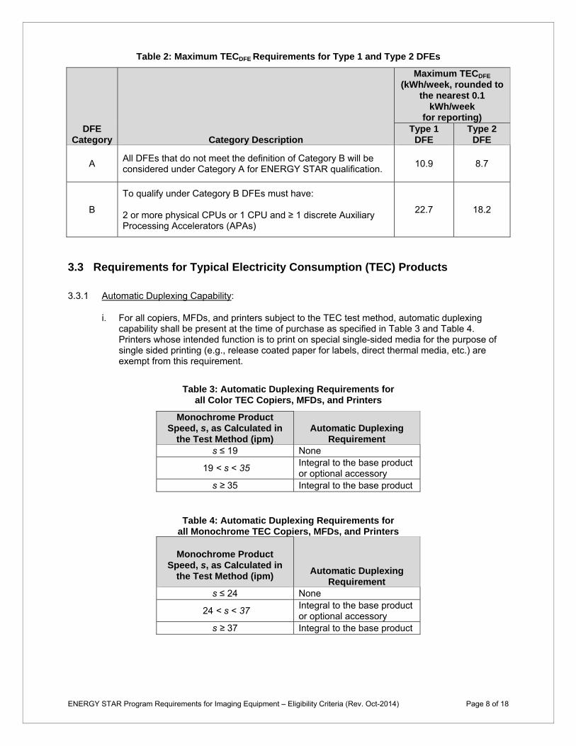
Table 2: Maximum TECDFE Requirements for Type 1 and Type 2 DFEs
DFE Category Category Description
Maximum TECDFE
(kWh/week, rounded to the nearest 0.1
kWh/week for reporting)
Type 1 DFE
Type 2 DFE
A All DFEs that do not meet the definition of Category B will be considered under Category A for ENERGY STAR qualification.
10.9 8.7
B
To qualify under Category B DFEs must have:
2 or more physical CPUs or 1 CPU and ≥ 1 discrete Auxiliary Processing Accelerators (APAs)
22.7 18.2
3.3 Requirements for Typical Electricity Consumption (TEC) Products
3.3.1 Automatic Duplexing Capability:
i. For all copiers, MFDs, and printers subject to the TEC test method, automatic duplexing capability shall be present at the time of purchase as specified in Table 3 and Table 4. Printers whose intended function is to print on special single-sided media for the purpose of single sided printing (e.g., release coated paper for labels, direct thermal media, etc.) are exempt from this requirement.
Table 3: Automatic Duplexing Requirements for all Color TEC Copiers, MFDs, and Printers
Monochrome Product Speed, s, as Calculated in
the Test Method (ipm) Automatic Duplexing
Requirement s ≤ 19 None
19 < s < 35 Integral to the base product or optional accessory
s ≥ 35 Integral to the base product
Table 4: Automatic Duplexing Requirements for all Monochrome TEC Copiers, MFDs, and Printers
Monochrome Product Speed, s, as Calculated in
the Test Method (ipm) Automatic Duplexing
Requirement s ≤ 24 None
24 < s < 37 Integral to the base product or optional accessory
s ≥ 37 Integral to the base product
ENERGY STAR Program Requirements for Imaging Equipment – Eligibility Criteria (Rev. Oct-2014) Page 8 of 18
ii. If a product is not certain to be bundled with an automatic duplex tray, the partner must make clear in their product literature, on their Web site, and in institutional sales literature that although the product meets the ENERGY STAR energy efficiency requirements, the product only fully qualifies for ENERGY STAR when bundled with or used with a duplexer tray. EPA asks that partners use the following language to convey this message to customers: "Achieves ENERGY STAR energy savings; product fully qualifies when packaged with (or used with) a duplex tray."
3.3.2 Typical Electricity Consumption: Calculated Typical Electricity Consumption (TEC) per Equation 3 or Equation 4 shall be less than or equal to the Maximum TEC Requirement (TECMAX) specified in Equation 6.
i. For Imaging Equipment with a Type 2 DFE that meet the Type 2 DFE maximum TECDFE
requirement in Table 2, the measured energy consumption of the DFE shall be divided by 0.80 to account for internal power supply losses and then excluded when comparing the product’s measured TEC value to TECMAX and for reporting.
ii. The DFE shall not interfere with the ability of the Imaging Equipment to enter or exit its lower-power modes.
iii. The energy use of a DFE can only be excluded if it meets the Type 2 DFE definition in Section 1 and is a separate processing unit that is capable of initiating activity over the network.
Example: A printer’s total TEC result is 24.50 kWh/wk and its Type 2 TECDFE value calculated in Section 3.2.4 is 9.0 kWh/wk. The TECDFE value is then divided by 0.80 to account for internal power supply losses with the Imaging Equipment in Ready State, resulting in 11.25 kWh/wk. The power supply adjusted value is subtracted from the tested TEC value: 24.50 kWh/wk – 11.25 kWh/wk = 13.25 kWh/wk. This 13.25 kWh/wk result is then compared to the relevant TECMAX to determine qualification
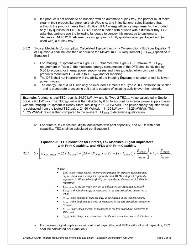
iv. For printers, fax machines, digital duplicators with print capability, and MFDs with print capability, TEC shall be calculated per Equation 3.
Equation 3: TEC Calculation for Printers, Fax Machines, Digital Duplicators with Print Capability, and MFDs with Print Capability
E ESLEEP SLEEPTEC 5 EJOB _ DAILY (2 EFINAL ) 24 (N JOBS 0.25) (2 t FINAL ) 48 ,t t SLEEP SLEEP
Where: TEC is the typical weekly energy consumption for printers, fax machines,
digital duplicators with print capability, and MFDs with print capability, expressed in kilowatt-hours (kWh) and rounded to the nearest 0.1 kWh for reporting;
EJOB_DAILY is the daily job energy, as calculated per Equation 5, in kWh; EFINAL is the final energy, as measured in the test procedure, converted to
kWh; NJOBS is the number of jobs per day, as calculated in the test procedure, tFINAL is the final time to Sleep, as measured in the test procedure, converted
to hours; ESLEEP is the Sleep energy, as measured in the test procedure, converted to
kWh; and tSLEEP is the Sleep time, as measured in the test procedure, converted to hours.
v. For copiers, digital duplicators without print capability, and MFDs without print capability, TEC shall be calculated per Equation 4.
ENERGY STAR Program Requirements for Imaging Equipment – Eligibility Criteria (Rev. Oct-2014) Page 9 of 18
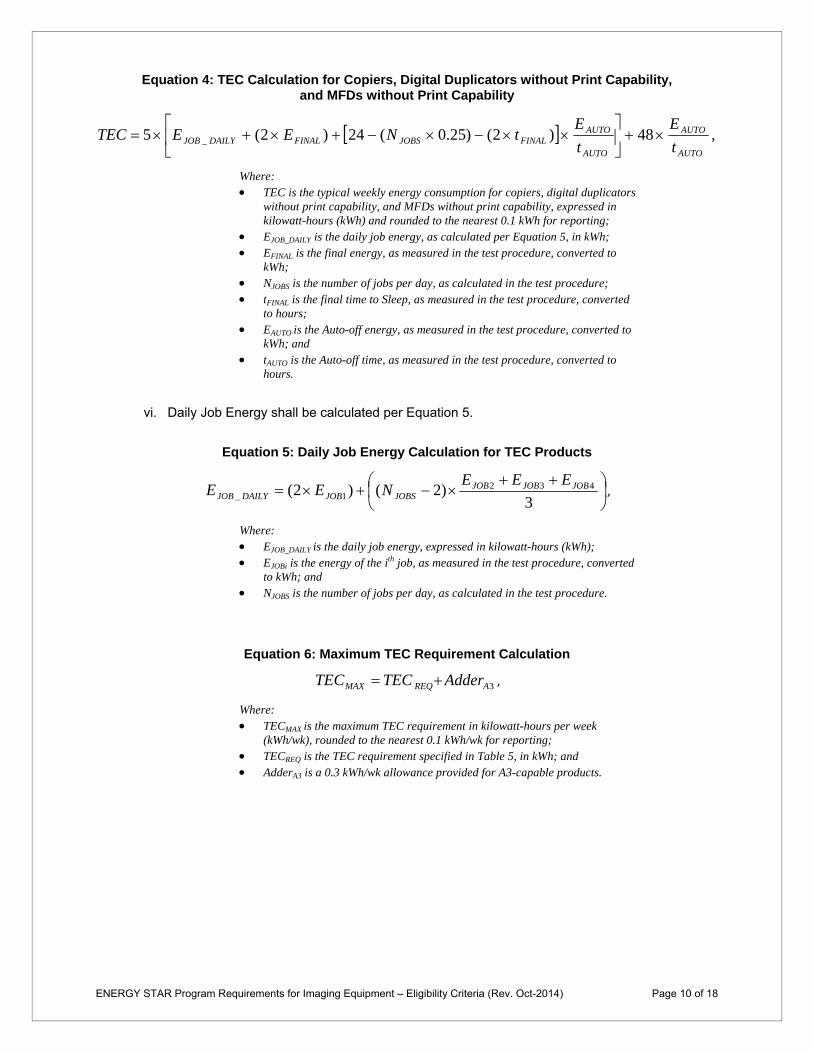
Equation 4: TEC Calculation for Copiers, Digital Duplicators without Print Capability, and MFDs without Print Capability
E EAUTO AUTOTEC 5 EJOB _ DAILY (2 EFINAL ) 24 (N JOBS 0.25) (2 t FINAL ) 48 ,t t AUTO AUTO
Where: TEC is the typical weekly energy consumption for copiers, digital duplicators
without print capability, and MFDs without print capability, expressed in kilowatt-hours (kWh) and rounded to the nearest 0.1 kWh for reporting;
EJOB_DAILY is the daily job energy, as calculated per Equation 5, in kWh; EFINAL is the final energy, as measured in the test procedure, converted to
kWh; NJOBS is the number of jobs per day, as calculated in the test procedure; tFINAL is the final time to Sleep, as measured in the test procedure, converted
to hours; EAUTO is the Auto-off energy, as measured in the test procedure, converted to
kWh; and tAUTO is the Auto-off time, as measured in the test procedure, converted to
hours.
vi. Daily Job Energy shall be calculated per Equation 5.
Equation 5: Daily Job Energy Calculation for TEC Products
EJOB2 EJOB3 EJOB4 EJOB _ DAILY (2 EJOB1) (N JOBS 2) , 3
Where: EJOB_DAILY is the daily job energy, expressed in kilowatt-hours (kWh); EJOBi is the energy of the ith job, as measured in the test procedure, converted
to kWh; and NJOBS is the number of jobs per day, as calculated in the test procedure.
Equation 6: Maximum TEC Requirement Calculation
TEC TEC Adder ,MAX REQ A3
Where: TECMAX is the maximum TEC requirement in kilowatt-hours per week
(kWh/wk), rounded to the nearest 0.1 kWh/wk for reporting; TECREQ is the TEC requirement specified in Table 5, in kWh; and AdderA3 is a 0.3 kWh/wk allowance provided for A3-capable products.
ENERGY STAR Program Requirements for Imaging Equipment – Eligibility Criteria (Rev. Oct-2014) Page 10 of 18

Table 5: TEC Requirement Before A3 Allowance (If Applicable)
Color Capability
Monochrome Product Speed, s, as Calculated
in the Test Method (ipm)
TECREQ
(kWh/week, to the nearest 0.1 kWh/week for reporting)
Monochrome Non-MFD
s ≤ 5 0.3 5 < s ≤ 20 ( s x 0.04 ) + 0.1 20 < s ≤ 30 ( s x 0.06 ) – 0.3 30 < s ≤ 40 ( s x 0.11 ) – 1.8
40 < s ≤ 65 ( s x 0.16 ) – 3.8 65 < s ≤ 90 ( s x 0.2 ) – 6.4
s > 90 ( s x 0.55 ) – 37.9
Monochrome MFD
s ≤ 5 0.4 5 < s ≤ 30 ( s x 0.07 ) + 0.05 30 < s ≤ 50 ( s x 0.11 ) – 1.15 50 < s ≤ 80 ( s x 0.25 ) – 8.15
s > 80 ( s x 0.6 ) – 36.15
Color Non-MFD
s ≤ 10 1.3 10 < s ≤ 15 ( s x 0.06 ) + 0.7 15 < s ≤ 30 ( s x 0.15 ) – 0.65 30 < s ≤ 75 ( s x 0.2 ) – 2.15
s > 75 ( s x 0.7 ) – 39.65
Color MFD
s ≤ 10 1.5 10 < s ≤ 15 ( s x 0.1 ) + 0.5 15 < s ≤ 30 ( s x 0.13 ) + 0.05 30 < s ≤ 70 ( s x 0.2 ) – 2.05 70 < s ≤ 80 ( s x 0.7 ) – 37.05
s > 80 ( s x 0.75 ) – 41.05
3.3.3 Additional Test Results Reporting Requirements:
i. Recovery times from various modes (Active 0, Active 1, Active 2 times) and Default Delay Time shall be reported for all products tested using the TEC test method.
ii. DFE model name/number, Ready State power, Sleep Mode power, and TECDFE shall be reported for any Type 1 DFE sold with an Imaging Equipment product, including those not tested with the Imaging Equipment product as part of the highest energy using configuration per Section 4.2.1iii.
3.4 Requirements for Operational Mode (OM) Products
3.4.1 Multiple Sleep Modes: If a product is capable of automatically entering multiple successive Sleep Modes, the same Sleep Mode shall be used to determine qualification under the Default Delay Time to Sleep requirements specified in Section 3.4.3 and the Sleep Mode power consumption requirements specified in Section 3.4.4.
3.4.2 DFE Requirements: For Imaging Equipment with a Type 2 DFE that relies on the Imaging Equipment for its power, and that meets the appropriate maximum TECDFE requirement found in Table 2, the DFE power shall be excluded subject to the following conditions:
i. Ready State power of the DFE, as measured in the test method, shall be divided by 0.60 to account for internal power supply losses.
ENERGY STAR Program Requirements for Imaging Equipment – Eligibility Criteria (Rev. Oct-2014) Page 11 of 18

Sleep Mode Requirements: If the resultant power in Paragraph i, above, is less than or equal to the Ready State or Sleep Mode power of the Imaging Equipment product as a whole, then the power shall be excluded from the measured Ready State or Sleep Mode power of the Imaging Equipment product as a whole when comparing to the Sleep Mode requirements in Section 3.4.4, below, and for reporting.
Otherwise, the Sleep Mode power of the DFE, as measured in the test method, shall be divided by 0.60 and excluded from the Ready or Sleep Mode power of the Imaging Equipment for comparing to the requirements, and for reporting.
Standby Requirements: If the resultant power in Paragraph i, above, is less than or equal to the Ready State, Sleep Mode, or Off Mode power of the Imaging Equipment as a whole, then the power shall be excluded from the Ready State, Sleep Mode, or Off Mode power of the Imaging Equipment product as a whole when comparing to the Standby requirements in Section 3.4.5, below, and for reporting.
Otherwise, the Sleep Mode power of the DFE, as measured in the test method, shall be divided by 0.60 and excluded from the Ready State,Sleep Mode, or Off Mode power of the Imaging Equipment for comparing to the requirements, and for reporting.
ii. The DFE must not interfere with the ability of the Imaging Equipment to enter or exit its lower-power modes.
iii. In order to take advantage of this exclusion, the DFE must meet the Type 2 DFE definition in Section 1 and be a separate processing unit that is capable of initiating activity over the network.
Examples: Product 1 is an Imaging Equipment product whose Type 2 DFE has no distinct sleep mode. The Type 2 DFE has measured Ready State and Sleep Mode power both equal to 30 watts. The measured Sleep Mode power of the product is 53 watts. When subtracting 50 watts (30 watts / 0.60) from the measured Sleep Mode power of the product, 53 watts, the resulting 3 watts is the Sleep Mode power of the product for use in the criteria limits below.
Product 2 is an Imaging Equipment product whose Type 2 DFE goes to sleep when the Imaging Equipment goes to sleep during testing. The Type 2 DFE has measured DFE Ready State and Sleep Mode power equal to 30 watts and 5 watts, respectively. The measured Sleep Mode power of the product is 12 watts. When subtracting 50 watts (30 watts / 0.60) from the measured Sleep Mode power of the product, 12 watts, the result is -38 watts. In this case, instead subtract 8.33 watts (5 watts / 0.60) from the measured Sleep Mode power of the product, 12 watts, resulting in 3.67 watts which is used in the criteria limits below.
3.4.3 Default Delay Time: Measured Default Delay Time to Sleep (tSLEEP) shall be less than or equal to the Required Default Delay Time to Sleep (tSLEEP_REQ) requirement specified in Table 6, subject to the following conditions:
i. The Default Delay Time to Sleep may not be adjusted by the user to be greater than the Maximum Machine Delay Time. This Maximum Machine Delay Time shall be set by the manufacturer at less than or equal to 4 hours.
ii. When reporting data and qualifying products that can enter Sleep Mode in multiple ways, partners should reference a Sleep level that can be reached automatically. If the product is capable of automatically entering multiple, successive Sleep levels, it is at the manufacturer’s discretion which of these levels is used for qualification purposes; however, the default-delay time provided must correspond with whichever level is used.
iii. Default Delay Time does not apply to OM products that can meet Sleep Mode requirements in Ready State.
ENERGY STAR Program Requirements for Imaging Equipment – Eligibility Criteria (Rev. Oct-2014) Page 12 of 18

Table 6: Required Default Delay Time to Sleep for OM Products
Product Type Media Format
Monochrome Product Speed, s,
as Calculated in the Test Method
(ipm or mppm)
Required Default Delay Time to
Sleep, tSLEEP_REQ
(minutes)*
Copier Large s ≤ 30 30 s > 30 60
Fax Machine Small or Standard All 5
MFD Small or Standard
s ≤ 10 15 10 < s ≤ 20 30
s > 20 60
Large s ≤ 30 30 s > 30 60
Printer Small or Standard
s ≤ 10 5 10 < s ≤ 20 15 20 < s ≤ 30 30
s > 30 60
Large s ≤ 30 30 s > 30 60
Scanner All All 15
Mailing Machine
All
s ≤ 50 20
50 < s ≤ 100 30
100 < s ≤ 150 40 s > 150 60
* Measured Default Delay Time to Sleep (tSLEEP) shall be less than or equal to the Required Default Delay Time to Sleep (tSLEEP REQ), as specified in Section 3.4.3.
3.4.4 Sleep Mode Power Consumption: Measured Sleep Mode power consumption (PSLEEP) shall be less than or equal to the maximum Sleep Mode power consumption requirement (PSLEEP_MAX) determined per Equation 7, subject to the following conditions:
i. Only those interfaces that are present and used during the test, including any fax interface, may be considered functional adders.
ii. Product functionality offered through a DFE shall not be considered a functional adder. iii. A single interface that performs multiple functions may be counted only once. iv. Any interface that meets more than one interface type definition shall be classified according
to the functionality used during the test. v. For products that meet the Sleep Mode power requirement in Ready State, no further
automatic power reductions are required to meet Sleep Mode requirements.
Equation 7: Calculation of Maximum Sleep Mode Power Consumption Requirement for OM products
n m
PSLEEP _ MAX PMAX _ BASE AdderINTERFACE AdderOTHER 1 1
Where: PSLEEP_MAX is the maximum Sleep Mode power consumption requirement,
expressed in watts (W), and rounded to the nearest 0.1 watt for reporting; PMAX_BASE is the maximum Sleep Mode power allowance for the base marking
engine, as determined per Table 7 , in watts; AdderINTERFACE is the power allowance for the interface functional adders
used during the test, including any fax capability, and as selected by the manufacturer from Table 8, in watts;
ENERGY STAR Program Requirements for Imaging Equipment – Eligibility Criteria (Rev. Oct-2014) Page 13 of 18

n is the number of allowances claimed for interface functional adders used during the test, including any fax capability, and is less than or equal to 2;
AdderOTHER is the power allowance for any non-interface functional adders in use during the test, as selected by the manufacturer from Table 8, in watts; and
m is the number of allowances claimed for any non-interface functional adders in use during the test, and is unlimited.
Table 7: Sleep Mode Power Allowance for Base Marking Engine
Product Type Media Format
Marking Technology
PMAX_BASE
(watts) Imp
act
Ink
Jet
All
Oth
er*
No
tA
pp
licab
le
Copier Large x 8.2 Fax Machine Standard x 0.6
Mailing Machine N/A x x 5.0
MFD Standard x x 0.6
Large x 4.9
x 8.2
Printer
Small x x x 4.0 Standard x x 0.6
Large x x 2.5
x 4.9 Scanner Any x 2.5
* “All Other” category includes High Performance Ink Jet.
Table 8: Sleep Mode Power Allowances for Functional Adders
Adder Type
Connection Type
Max. Data
Rate, r (Mbit/
second) Details
Functional Adder
Allowance (watts)
r < 20 Includes: USB 1.x, IEEE 488, IEEE 1284/Parallel/ Centronics, RS232
0.2
Wired
20 ≤ r < 500
Includes: USB 2.x, IEEE 1394/ FireWire/i.LINK, 100Mb Ethernet
0.4
r ≥ 500 Includes: USB 3.x,1G Ethernet 0.5
Interface Any
Includes: Flash memory-card/smart-card readers, camera interfaces, PictBridge
0.2
Fax Modem Any Applies to Fax Machines and MFDs only.
0.2
Wireless, Radio-
frequency (RF)
Any Includes: Bluetooth, 802.11 2.0
Wireless, Infrared (IR)
Any Includes: IrDA. 0.1
ENERGY STAR Program Requirements for Imaging Equipment – Eligibility Criteria (Rev. Oct-2014) Page 14 of 18

Adder Type
Connection Type
Max. Data
Rate, r (Mbit/
second) Details
Functional Adder
Allowance (watts)
Cordless Handset
N/A N/A
Capability of the Imaging Equipment to communicate with a cordless handset. Applied only once, regardless of the number of cordless handsets the product is designed to handle. Does not address the power requirements of the cordless handset itself.
0.8
Memory N/A N/A
Applies to the internal capacity available in the Imaging Equipment for storing data. Applies to all volumes of internal memory and should be scaled accordingly for RAM. This adder does not apply to hard disk or flash memory.
0.5/GB
Scanner N/A N/A
Applies to MFDs and Copiers only. Includes: Cold Cathode Fluorescent Lamp (CCFL) or a technology other than CCFL, such as Light-Emitting Diode (LED), Halogen, Hot-Cathode Fluorescent Tube (HCFT), Xenon, or Tubular Fluorescent (TL) technologies. (Applied only once, regardless of the lamp size or the number of lamps/bulbs employed.)
0.5
Power Supply
N/A N/A
Applies to both internal and external power supplies of Mailing Machines and Standard Format products using Inkjet and Impact marking technologies with nameplate output power (POUT) greater than 10 watts.
0.02 x (POUT – 10.0)
Touch Panel
Display N/A N/A
Applies to both monochrome and color touch panel displays.
0.2
Internal Disk
Drives N/A N/A
Includes any high-capacity storage product, including hard-disk and solid-state drives. Does not cover interfaces to external drives.
0.15
3.4.5 Standby Power Consumption: Standby Mode power, which is the lesser of the Ready State Power, Sleep Mode Power, and Off Mode Power, as measured in the test procedure, shall be less than or equal to the Maximum Standby Power specified in Table 9, subject to the following condition.
i. The Imaging Equipment shall meet the Standby Power requirement independent of the state of any other devices (e.g., a host PC) connected to it.
Table 9: Maximum Standby Power Requirement
Product Type Maximum Standby Power
(watts) All OM Products 0.5
ENERGY STAR Program Requirements for Imaging Equipment – Eligibility Criteria (Rev. Oct-2014) Page 15 of 18

Note: Products intended for sale in the US market are subject to minimum toxicity and recyclability requirements. Please see ENERGY STAR Program Requirements for Imaging Equipment: Partner Commitments for details.
4 TESTING
4.1 Test Methods
4.1.1 When testing Imaging Equipment products, the test methods identified in Table 10 shall be used to determine qualification for ENERGY STAR.
Table 10: Test Methods for ENERGY STAR Qualification
Product Type Test Method
All Products ENERGY STAR Imaging Equipment Test Method, Rev. Sep-2014
4.2 Number of Units Required for Testing
4.2.1 Representative Models shall be selected for testing per the following requirements:
i. For qualification of an individual product model, a product configuration equivalent to that which is intended to be marketed and labeled as ENERGY STAR is considered the Representative Model;
ii. For qualification of a product family that does not include a Type 1 DFE, the highest energy using configuration within the family shall be considered the Representative Model. Any subsequent testing failures (e.g., as part of verification testing) of any model in the family will have implications for all models in the family.
iii. For qualification of a product family that includes Type 1 DFE, the highest energy using configuration of the Imaging Equipment and highest energy using DFE within the family shall be tested for qualification purposes. Any subsequent testing failures (e.g., as part of verification testing) of any model in the family and all Type 1 DFEs sold with the Imaging Equipment, including those not tested with the Imaging Equipment product, will have implications for all models in the family. Imaging Equipment products that do not incorporate a Type 1 DFE may not be added to this product family for qualification and must be qualified as a separate family without a Type 1 DFE.
4.2.2 A single unit of each Representative Model shall be selected for testing.
4.3 International Market Qualification
4.3.1 Products shall be tested for qualification at the relevant input voltage/frequency combination for each market in which they will be sold and promoted as ENERGY STAR.
ENERGY STAR Program Requirements for Imaging Equipment – Eligibility Criteria (Rev. Oct-2014) Page 16 of 18

5 USER INTERFACE 5.1.1 Manufacturers are encouraged to design products in accordance with the user interface standard
IEEE 1621: Standard for User Interface Elements in Power Control of Electronic Devices Employed in Office/Consumer Environments. For details, see http://eetd.LBL.gov/Controls.
6 EFFECTIVE DATE 6.1.1 Effective Date: The Version 2.0 ENERGY STAR Imaging Equipment specification shall take effect
on January 1, 2014. To qualify for ENERGY STAR, a product model shall meet the ENERGY STAR specification in effect on its date of manufacture. The date of manufacture is specific to each unit and is the date on which a unit is considered to be completely assembled.
6.1.2 Future Specification Revisions: EPA reserves the right to change this specification should technological and/or market changes affect its usefulness to consumers, industry, or the environment. In keeping with current policy, revisions to the specification are arrived at through stakeholder discussions. In the event of a specification revision, please note that the ENERGY STAR qualification is not automatically granted for the life of a product model.
6.1.3 Items for Consideration in a Future Revision:
i. Test Method Changes: EPA and DOE will continue to monitor the implementation of proxying capability in Imaging Equipment hardware and consider the development of a test method to determine the presence of a network proxy (e.g., one compliant with ECMA-393 ProxZzzy for Sleeping Hosts). EPA and DOE will also evaluate the possibility of measuring and reporting as-shipped product speed, recovery time from Sleep or Off Modes for OM products, and wakeup from Sleep Mode caused by common network events.
ii. TEC Requirements in Kilowatt-hours per Year: EPA has added columns to the TEC Tables expressing the requirements in kilowatt-hours per year in addition to the currently-used kilowatt-hours per week. Although this is purely informative, EPA will consider making this unit the only way to express TEC in a future specification revision as a way to address issues with reporting accuracy and comparisons between other ENERGY STAR products (which typically report in kilowatt-hours/year).
iii. Equipment for Printing and Scanning Media Other than Paper: EPA often receives questions about qualifying products that print or scan media other than paper (e.g., cloth, microfilm, etc.) and welcomes data on their energy consumption. Such data would support development of requirements for these products in a future version of the specification.
iv. Professional Products (High-speed TEC Products for Printing on Heavier, Larger Paper): EPA has learned that some high-speed TEC products have additional requirements for handling larger and heavier paper. EPA will consider separating these into a separate category in a future version of the specification.
v. Decoupled Requirements for TEC Categories: In Version 1 and 2 Imaging Equipment specifications, EPA assumed that color products would have higher TEC than monochrome products due to their additional complexity, and multi-function would have higher TEC than single-function. The TEC requirements were structured to reflect this relationship. However, EPA has recently learned that color MFDs—a premium product—can incorporate energy saving features that decrease their energy consumption below that for monochrome non-MFDs. EPA will therefore consider decoupling the TEC requirements in the future to recognize the highest performers among all TEC categories.
ENERGY STAR Program Requirements for Imaging Equipment – Eligibility Criteria (Rev. Oct-2014) Page 17 of 18

vi. Scope Reevaluation: EPA may re-assess the current market for Imaging Equipment to determine whether the current scope of included products is still relevant and whether ENERGY STAR label continues to provide a market differentiation for all product classes included in scope.
vii. Expanding Duplexing Requirements: EPA may re-assess the requirements for the presence of duplexing as integral to the base product and consider how the optional requirements could be made more stringent. Changing the requirements to result in greater coverage of products with duplexing integral to the base marking engine could reduce paper usage.
ENERGY STAR Program Requirements for Imaging Equipment – Eligibility Criteria (Rev. Oct-2014) Page 18 of 18

ENERGY STAR® Program Requirements Product Specification for Imaging Equipment
Test Method for Determining Imaging Equipment Energy Use
Rev. Sep-2014
1 OVERVIEW
The following test method shall be used for determining product compliance with requirements in the ENERGY STAR Eligibility Criteria for Imaging Equipment.
2 APPLICABILITY ENERGY STAR test requirements are dependent upon the feature set of the products under evaluation. Table 1 shall be used to determine the applicability of each section of this document.
Table 1: Test Procedure Applicability
Product Type Media Format Marking Technology ENERGY STAR
Evaluation Method
Copier
Standard Direct Thermal (DT), Dye Sublimation
(DS), Electro-photographic (EP), Solid Ink (SI), Thermal Transfer (TT)
Typical Energy Consumption (TEC)
Large DT, DS, EP, SI, TT Operational Mode
(OM)
Digital Duplicator Standard Stencil TEC
Fax Machine Standard DT, DS, EP, SI, TT TEC
Ink Jet (IJ) OM
Mailing Machine All DT, EP, IJ, TT OM
Multifunction Device (MFD)
Standard
High Performance IJ, DT, DS, EP, SI, TT
TEC
IJ, Impact OM
Large High Performance IJ, DT, DS, EP, IJ,
SI, TT OM
Printer
Standard
High Performance IJ, DT, DS, EP, SI, TT
TEC
IJ, Impact OM
Large or Small DT, DS, EP, Impact, IJ, SI, TT OM
Large High Performance IJ OM
Small High Performance IJ TEC
Scanner All N/A OM
ENERGY STAR Program Requirements for Imaging Equipment – Test Method (Rev. Sep-2014) Page 1 of 16

3 DEFINITIONS
Unless otherwise specified, all terms used in this document are consistent with the definitions in the ENERGY STAR Eligibility Criteria for Imaging Equipment.
4 TEST SETUP
4.1 General Test Setup
A) Test Setup and Instrumentation: Test setup and instrumentation for all portions of this procedure shall be in accordance with the requirements of International Electrotechnical Commission (IEC) Standard 62301, Ed. 2.0, “Measurement of Household Appliance Standby Power”, Section 4, “General Conditions for Measurements.” In the event of conflicting requirements, the ENERGY STAR test method shall take precedence.
B) Ac Input Power: Products intended to be powered from an ac mains power source shall be connected to a voltage source appropriate for the intended market, as specified in Table 2 or Table 3.
1) Products shipped with external power supplies (EPSs) shall first be connected to the EPS and then to the voltage source specified in Table 2 or Table 3.
2) If a product is rated to operate at a voltage/frequency combination in a specific market that is different from the voltage/frequency combination for that market (e.g., 230 volts (V), 60 hertz (Hz) in North America), the unit shall be tested at the manufacturer rated voltage/frequency combination for that unit. The voltage/frequency used shall be reported.
Table 2: Input Power Requirements for Products with Nameplate Rated Power Less Than or Equal to 1500 W
Market Voltage Voltage
Tolerance
Maximum Total
Harmonic Distortion
Frequency Frequency Tolerance
North America, Taiwan 115 V ac +/- 1.0 % 2.0 % 60 Hz +/- 1.0 %
Europe, Australia, New Zealand
230 V ac +/- 1.0 % 2.0 % 50 Hz +/- 1.0 %
Japan 100 V ac +/- 1.0 % 2.0 % 50 Hz or 60 Hz +/- 1.0 %
Table 3: Input Power Requirements for Products with Nameplate Rated Power Greater than 1500 W
Market Voltage Voltage
Tolerance
Maximum Total
Harmonic Distortion
Frequency Frequency Tolerance
North America, Taiwan 115 V ac +/- 4.0 % 5.0 % 60 Hz +/- 1.0 %
Europe, Australia, New Zealand
230 V ac +/- 4.0 % 5.0 % 50 Hz +/- 1.0 %
Japan 100 V ac +/- 4.0 % 5.0 % 50 Hz or 60 Hz +/- 1.0 %
ENERGY STAR Program Requirements for Imaging Equipment – Test Method (Rev. Sep-2014) Page 2 of 16

C) Low-voltage Dc Input Power:
1) Products may be powered with a low-voltage dc source (e.g., via network or data connection) only if the dc source is the only acceptable source of power for the product (i.e., no ac plug or EPS is available).
2) Products powered by low-voltage dc shall be configured with an ac source of the dc power for testing (e.g., an ac-powered universal serial bus (USB) hub).
a) The ac source of the dc power used for testing shall be recorded and reported for all tests.
3) Power for the unit under test (UUT) shall include the following, as measured per Section 5 of this method:
a) Ac power consumption of the low-voltage dc source with the UUT as the load (PL); and
b) Ac power consumption of the low-voltage dc source with no load (PS).
D) Ambient Temperature: Ambient temperature shall be 23°C ± 5°C.
E) Relative Humidity: Relative humidity shall be between 10% and 80%.
F) Power Meter: Power meters shall possess the following attributes:
1) Minimum Frequency Response: 3.0 kHz
2) Minimum Resolution:
a) 0.01 W for measurement values less than 10 W;
b) 0.1 W for measurement values from 10 W to 100 W;
c) 1 W for measurement values from 100 W to 1.5 kW; and
d) 10 W for measurement values greater than 1.5 kW.
e) Measurements of accumulated energy should have resolutions which are generally consistent with these values when converted to average power. For accumulated energy measurements, the figure of merit for determining required accuracy is the maximum power value during the measurement period, not the average, since it is the maximum that determines the metering equipment and setup.
G) Measurement Uncertainty1:
1) Measurements of greater than or equal to 0.5 W shall have an uncertainty of 2% or better at the 95% confidence level.
2) Measurements of less than 0.5 W shall have an uncertainty of 0.02 W or better at the 95% confidence level.
H) Time Measurement: Time measurements may be performed with a standard stopwatch or other time keeping device with a resolution of at least 1 second.
I) Paper Specifications:
1) Standard Format Products shall be tested in accordance with Table 4.
2) Large, Small, and Continuous Format products shall be tested using any compatible paper size.
1 Measurement uncertainty calculations should be performed according IEC 62301 Ed. 2.0 Appendix D.
Only the uncertainty due to the measurement instrument shall be calculated.
ENERGY STAR Program Requirements for Imaging Equipment – Test Method (Rev. Sep-2014) Page 3 of 16

Table 4: Paper Size and Weight Requirements
Market Paper Size Basis Weight
(g/m2)
North America / Taiwan 8.5” × 11” 75
Europe / Australia / New Zealand A4 80
Japan A4 64
5 LOW-VOLTAGE DC SOURCE MEASUREMENT FOR ALL PRODUCTS
1) Connect the dc source to the power meter and relevant ac supply as specified in Table 2.
2) Verify that the dc source is unloaded.
3) Allow the dc source to stabilize for a minimum of 30 minutes.
4) Measure and record the unloaded dc source power (PS) according to section 9.1.A.1 of this test method.
6 PRE-TEST UUT CONFIGURATION FOR ALL PRODUCTS
6.1 General Configuration
A) As-shipped Condition: All products shall be tested in their “as-shipped” configuration unless otherwise specified by this test method.
B) Product Speed for Calculations and Reporting: The product speed for all calculations and reporting shall be the highest speed as claimed by the manufacturer per the following criteria, expressed in images per minute (ipm) and rounded to the nearest integer:
1) In general, for Standard-size products, a single A4 or 8.5” × 11” sheet printed/copied/scanned on one side in one minute is equal to 1 (ipm).
a) When operating in duplex mode a single A4 or 8.5” × 11” sheet printed/copied/scanned on
both sides in one minute is equal to 2 (ipm).
2) For all products, the product speed shall be based on:
a) The highest manufacturer-claimed monochrome print speed, unless the product cannot print, in which case,
b) The highest manufacturer-claimed monochrome copy speed, unless the product cannot print or copy, in which case,
c) The manufacturer-claimed scan speed.
d) When a manufacturer intends to qualify a product in a certain market by making use of test results that qualified the product in another market using other sizes of paper (e.g., A4 versus 8.5” × 11”), and if its maximum claimed speeds differ when producing images on different sizes of paper, the highest speed shall be used.
ENERGY STAR Program Requirements for Imaging Equipment – Test Method (Rev. Sep-2014) Page 4 of 16

Table 5: Calculation of Product Speed for Standard, Small, and Large Format Products with the Exception of Mailing Machines
Media Format
Media Size
Product Speed, s (ipm)
Where:
sP is the maximum claimed monochrome speed in images per minute when processing the given media,
w is the width of the media, in meters (m),
is the length of the media, in meters (m).
Standard 8.5” × 11” sP
A4 sP
4” × 6” 0.25 × sP
Small A6 0.25 × sP
Smaller than A6 or 4” × 6” 16 × w × × sP
Large A2 4 × sP
A0 16 × sP
3) For Continuous Form products, product speed shall be calculated per Equation 1
Equation 1: Calculation of Product Speed
Lsws 16
Where: s is the product speed, in ipm, w is the width of the media, in meters (m), sL is the maximum claimed monochrome speed, in meters per
minute.
4) For Mailing Machines, product speed shall be reported in units of mail pieces per minute (mppm).
5) The product speed used for all calculations and qualification, as calculated above, may not be the same as the product speed used for testing.
C) Color: Color-capable products shall be tested making monochrome (black) images.
1) For those products without black ink, a composite black shall be used.
D) Network Connections: Products that are capable of being network-connected as-shipped shall be connected to a network.
1) Products shall be connected to only one network or data connection for the duration of the test.
a) Only one computer may be connected to the UUT, either directly or via a network.
2) The type of network connection depends on the characteristics of the UUT and shall be the topmost connection listed in Table 6 available on the unit as-shipped.
ENERGY STAR Program Requirements for Imaging Equipment – Test Method (Rev. Sep-2014) Page 5 of 16

Table 6: Network or Data Connections for Use in Test
Order of Preference for Use in Test (if Provided by UUT)
Connections for all Products
1 Ethernet – 1 Gb/s
2 Ethernet – 100/10 Mb/s
3 USB 3.x
4 USB 2.x
5 USB 1.x
6 RS232
7 IEEE 12842
8 Wi-Fi
9 Other Wired – in order of
preference from highest to lowest speed
10 Other Wireless – in order of preference from highest to
lowest speed
11 If none of the above, test with
whatever connection is provided by the device (or none)
3) Products connected to Ethernet, per paragraph 6.1.D)2) above, and capable of supporting Energy Efficient Ethernet (IEEE Standard 802.3az)
3, shall be connected to a network switch or
router that also supports Energy Efficient Ethernet for the duration of the test.
4) In all cases the type of connection used during the test shall be reported.
E) Service/Maintenance Modes: UUTs shall never be in service/maintenance modes, including color calibration, during testing.
1) Service/Maintenance modes shall be disabled prior to testing.
2) Manufacturers shall provide instructions detailing how to disable service/maintenance modes if this information is not included in the product documentation packaged with the UUT or is not readily available online.
3) If service/maintenance modes cannot be disabled and a service/maintenance mode occurs during a job other than the first job, the results from the job with the service/maintenance mode shall be replaced with results from a substitute job. In this case, the substitute job shall be inserted into the test procedure immediately following Job 4 and the inclusion of the substitute job shall be reported. Each job period shall be 15 minutes.
2 Also referred to as a Parallel or Centronics interface.
3 Institute of Electrical and Electronics Engineers (IEEE) Standard 802.3az-2010. “IEEE Standard for
Information Technology—Telecommunications and Information Exchange Between Systems—Local and Metropolitan Area Networks—Specific Requirements—Part 3: Carrier Sense Multiple Access with Collision Detection (CSMA/CD) Access Method and Physical Layer Specifications.” 2010.
ENERGY STAR Program Requirements for Imaging Equipment – Test Method (Rev. Sep-2014) Page 6 of 16

6.2 Configuration for Fax Machines
A) All fax machines and MFDs with fax capability that connect to a telephone line shall be connected to a telephone line during the test, in addition to the network connection specified by Table 6 if the UUT is network capable.
1) In the case that a working phone line is not available, a line simulator may be used as a replacement.
2) Only fax machines shall be tested using the fax capability.
B) Fax machines shall be tested with one image per job.
6.3 Configuration for Digital Duplicators
A) Except as noted below, digital duplicators shall be configured and tested as printers, copiers, or MFDs, depending on their capabilities as-shipped.
1) Digital duplicators shall be tested at maximum claimed speed, which is also the speed that should be used to determine the job size for performing the test, not at the default as-shipped speed, if different.
2) For digital duplicators, there shall be only one original image.
7 PRE-TEST UUT INITIALIZATION FOR ALL PRODUCTS
7.1 General Initialization
A) Prior to the start of testing, the UUT shall be initialized as follows:
1) Set up the UUT per the instructions in the Manufacturer’s Instructions or documentation.
a) Accessories, such as paper source, that are shipped with the base product and are intended to be installed or attached by the end-user shall be installed as intended for the product model. Paper shall be placed in all paper sources designated to hold the paper specified for testing, and the UUT shall pull from the default paper source, using the as-shipped paper source settings.
b) If the product is connected to a computer, either directly or via a network, during the test, the computer shall be running the newest version of the manufacturer’s default driver available at the time of testing using settings corresponding to the default settings upon shipment, unless otherwise specified in this test method. The print driver version used for testing shall be recorded.
i) In the event that a setting does not have a default and is not defined in this test method, the setting shall be set according to the tester’s discretion and shall be recorded.
ii) When connecting via a network and multiple computers are connected to the network, print driver settings apply only to the computer sending the print jobs to the UUT.
c) For products designed to operate on battery power when not connected to the mains power
source, the battery shall be removed for all tests. For UUTs where operation without a battery
pack is not a supported configuration, the test shall be performed with fully charged battery
pack(s) installed, making sure to report this configuration in the test results. To ensure the
battery is fully charged, perform the following steps:
i) For UUTs that have an indicator to show that the battery is fully charged, continue charging for an additional 5 hours after the indication is present.
ENERGY STAR Program Requirements for Imaging Equipment – Test Method (Rev. Sep-2014) Page 7 of 16

ii) If there is no charge indicator, but the manufacturer’s instructions provide a time estimate for when charging this battery or this capacity of battery should be complete, continue charging for an additional 5 hours after the manufacturer’s indication.
iii) If there is no indicator and no time estimate in the instructions, the duration shall be 24 hours.
2) Connect the UUT to its power source.
3) Power on the UUT and perform initial system configuration, as applicable. Verify that default delay times are configured according to product specifications and/or manufacturer recommendations.
a) Product Speed for Testing: The product shall be tested with speed settings in their default as-shipped configuration.
b) Auto-off for TEC Products: If a printer, digital duplicator, fax machine, or MFD with print-capability has Auto-off capability and it is enabled as-shipped, it shall be disabled prior to testing.
c) Auto-off for OM Products: If a product has an Auto-off Mode enabled as-shipped, it shall remain enabled for the duration of testing.
4) User-controllable anti-humidity features shall be turned off or disabled for the duration of testing.
5) Pre-conditioning: Place the UUT in Off Mode, then let the UUT sit idle for 15 minutes.
a) For EP-TEC products, let the UUT sit in Off Mode for an additional 105 minutes, for a total of at least 120 minutes (2 hours).
b) Pre-conditioning is only required prior to beginning the first test on each UUT.
8 TYPICAL ENERGY CONSUMPTION (TEC) TEST PROCEDURE
8.1 Job Structure
A) Jobs per Day: The number of jobs per day (NJOBS) is specified in Table 7.
Table 7: Number of Jobs per Day (NJOBS)
Monochrome Product Speed, s
(ipm)
Jobs per Day
(NJOBS)
s ≤ 8 8
8 < s < 32 s
s ≥ 32 32
B) Images per Job: Except for fax machines, the number of images shall be computed according to
Equation 2, below. For convenience, Table 11 at the end of this document provides the resultant
images per job computation for each integer product speed up through 100 ipm.
ENERGY STAR Program Requirements for Imaging Equipment – Test Method (Rev. Sep-2014) Page 8 of 16

Equation 2: Calculation of Number of Images per Job
ቧ ቃ ቃ ቪ
ሮቦዘቫ ሼ ቃሪሯ ቑሤኺኮኴኲዀ ቀ ቄ ኃኈ ሼ ሽ ቃ ቆ ቪ
ሤኼኯዀ
Where:
NIMAGES is the number of images per job, rounded down
(truncated) to the nearest integer,
s is the product speed in images per minute (ipm), calculated in
section 6.1.B), of this test procedure, and
NJOBS is the number of jobs per day, as calculated per
Table 7.
C) Test Image: Test Pattern A from International Organization for Standardization (ISO)/IEC Standard 10561:1999 shall be used as the original image for all testing.
1) Test images shall be rendered in 10 point size in a fixed-width Courier font (or nearest equivalent).
2) German-specific characters need not be reproduced if the product is incapable of German character reproduction.
D) Print Jobs: Print jobs for the test shall be sent over the network connection designated in Table 6 immediately before printing each job.
1) Each image in a print job shall be sent separately, (i.e., all images may be part of the same document), but shall not be specified in the document as multiple copies of a single original image (unless the product is a digital duplicator).
2) For printers and MFDs that can interpret a page description language (PDL) (e.g., Printer Command Language PCL, Postscript), images shall be sent to the product in a PDL.
E) Copy Jobs:
1) For copiers with speed less than or equal to 20 ipm, there shall be one original per required image.
2) For copiers with speed greater than 20 ipm, it may not be possible to match the number of required original images (i.e., due to limits on document feeder capacity). In this case, it is permissible to make multiple copies of each original, and the number of originals shall be greater than or equal to ten.
Example: For a 50 ipm unit that requires 39 images per job, the test may be performed with four copies of 10 originals or three copies of 13 originals.
3) Originals may be placed in the document feeder before the test begins.
a) Products without a document feeder may make all images from a single original placed on the platen.
F) Fax Jobs: Fax jobs shall be sent via the connected phone line or line simulator immediately before performing each job.
ENERGY STAR Program Requirements for Imaging Equipment – Test Method (Rev. Sep-2014) Page 9 of 16
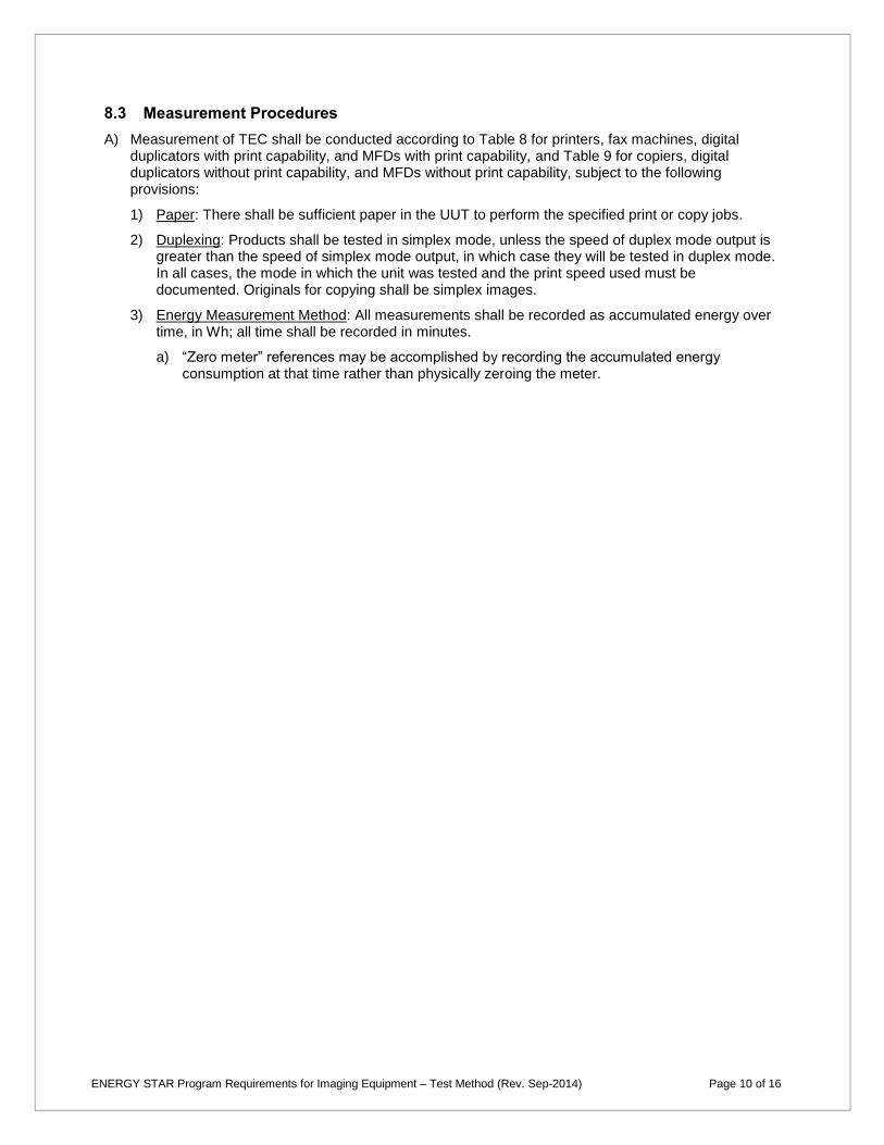
8.3 Measurement Procedures
A) Measurement of TEC shall be conducted according to Table 8 for printers, fax machines, digital duplicators with print capability, and MFDs with print capability, and Table 9 for copiers, digital duplicators without print capability, and MFDs without print capability, subject to the following provisions:
1) Paper: There shall be sufficient paper in the UUT to perform the specified print or copy jobs.
2) Duplexing: Products shall be tested in simplex mode, unless the speed of duplex mode output is greater than the speed of simplex mode output, in which case they will be tested in duplex mode. In all cases, the mode in which the unit was tested and the print speed used must be documented. Originals for copying shall be simplex images.
3) Energy Measurement Method: All measurements shall be recorded as accumulated energy over time, in Wh; all time shall be recorded in minutes.
a) “Zero meter” references may be accomplished by recording the accumulated energy consumption at that time rather than physically zeroing the meter.
ENERGY STAR Program Requirements for Imaging Equipment – Test Method (Rev. Sep-2014) Page 10 of 16

SLEEPE
SLEEPt
Table 8: TEC Test Procedure for Printers, Fax Machines, Digital Duplicators with Print Capability, and MFDs with Print Capability
Step Initial State
Action Record (at
end of step) Unit of
Measure
Possible States
Measured
1 Off
Connect the UUT to the meter. Ensure the unit is powered and in Off Mode. Zero the meter; measure energy over 5 minutes or more. Record both energy and time.
Off energy Watt-hours
(Wh) Off
Testing Interval time
Minutes (min)
2 Off Turn on unit. Wait until unit indicates it is in Ready Mode.
– – –
3 Ready
Print a job of at least one output image but no more than a single job per Table 11. Measure and record time to first sheet exiting unit.
Active0 time Minutes
(min) –
4 Ready
(or other)
Wait until the meter shows that the unit has entered its final Sleep Mode or the time specified by the manufacturer.
– – –
5 Sleep Zero meter; measure energy and time over 1 hour. Record the energy and time.
Sleep energy, Watt-hours
(Wh)
Sleep Sleep time,
(≤ 1 hour)
Minutes (min)
6 Sleep
Zero meter and timer. Print one job (calculated above). Measure energy and time. Record time to first sheet exiting unit. Measure energy over 15 minutes from job initiation. The job must finish within the 15 minutes.
Job1 energy, EJOB1
Watt-hours (Wh) Recovery,
Active, Ready, Sleep Active1 time
Minutes (min)
7 Ready
(or other) Repeat Step 6.
Job2 energy, EJOB2
Watt-hours (Wh) Same as
above Active2 time
Minutes (min)
8 Ready
(or other) Repeat Step 6 (without Active time measurement).
Job3 energy, EJOB3
Watt-hours (Wh)
Same as above
9 Ready
(or other) Repeat Step 6 (without Active time measurement).
Job4 energy, EJOB4
Watt-hours (Wh)
Same as above
10 Ready
(or other)
Zero meter and timer. Measure energy and time until meter and/or unit shows that unit has entered Sleep Mode or the final Sleep Mode for units with multiple Sleep modes, or the time specified by the manufacturer, if provided. Record energy and time.
Final energy, EFINAL
Watt-hours (Wh)
Ready, Sleep Final time,
tFINAL
Minutes (min)
Notes:
Steps 4 and 10: For those units that do not indicate when they have entered the Final Sleep
Mode, manufacturers shall specify the time to Final Sleep Mode for testing purposes.
ENERGY STAR Program Requirements for Imaging Equipment – Test Method (Rev. Sep-2014) Page 11 of 16
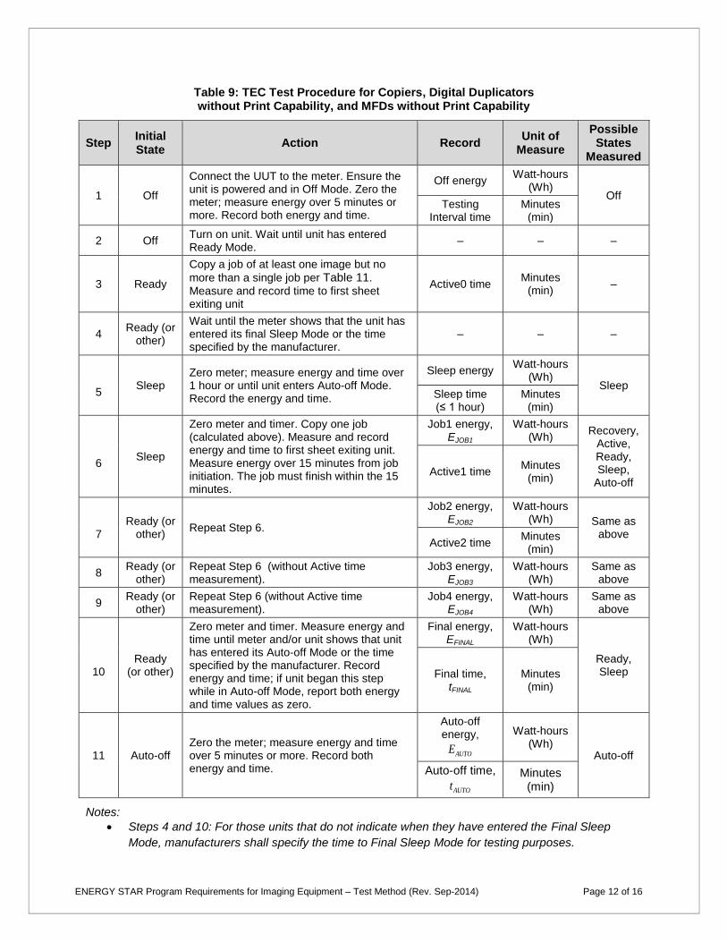
AUTOE
AUTOt
Table 9: TEC Test Procedure for Copiers, Digital Duplicators without Print Capability, and MFDs without Print Capability
Step Initial State
Action Record Unit of
Measure
Possible States
Measured
1 Off
Connect the UUT to the meter. Ensure the unit is powered and in Off Mode. Zero the meter; measure energy over 5 minutes or more. Record both energy and time.
Off energy Watt-hours
(Wh) Off
Testing Interval time
Minutes (min)
2 Off Turn on unit. Wait until unit has entered Ready Mode.
– – –
3 Ready
Copy a job of at least one image but no
more than a single job per Table 11.
Measure and record time to first sheet exiting unit
Active0 time Minutes
(min) –
4 Ready (or
other)
Wait until the meter shows that the unit has entered its final Sleep Mode or the time specified by the manufacturer.
– – –
5 Sleep
Zero meter; measure energy and time over 1 hour or until unit enters Auto-off Mode. Record the energy and time.
Sleep energy Watt-hours
(Wh) Sleep
Sleep time (≤ 1 hour)
Minutes (min)
6 Sleep
Zero meter and timer. Copy one job (calculated above). Measure and record energy and time to first sheet exiting unit. Measure energy over 15 minutes from job initiation. The job must finish within the 15 minutes.
Job1 energy, EJOB1
Watt-hours (Wh)
Recovery, Active, Ready, Sleep,
Auto-off Active1 time
Minutes (min)
7 Ready (or
other) Repeat Step 6.
Job2 energy, EJOB2
Watt-hours (Wh) Same as
above Active2 time
Minutes (min)
8 Ready (or
other) Repeat Step 6 (without Active time measurement).
Job3 energy, EJOB3
Watt-hours (Wh)
Same as above
9 Ready (or
other) Repeat Step 6 (without Active time measurement).
Job4 energy, EJOB4
Watt-hours (Wh)
Same as above
10 Ready
(or other)
Zero meter and timer. Measure energy and time until meter and/or unit shows that unit has entered its Auto-off Mode or the time specified by the manufacturer. Record energy and time; if unit began this step while in Auto-off Mode, report both energy and time values as zero.
Final energy, EFINAL
Watt-hours (Wh)
Ready, Sleep Final time,
tFINAL
Minutes (min)
11 Auto-off Zero the meter; measure energy and time over 5 minutes or more. Record both energy and time.
Auto-off energy, Watt-hours
(Wh) Auto-off
Auto-off time, Minutes (min)
Notes:
Steps 4 and 10: For those units that do not indicate when they have entered the Final Sleep
Mode, manufacturers shall specify the time to Final Sleep Mode for testing purposes.
ENERGY STAR Program Requirements for Imaging Equipment – Test Method (Rev. Sep-2014) Page 12 of 16

9 OPERATIONAL MODE (OM) TEST PROCEDURE
9.1 Measurement Procedures
A) Measurement of OM power and delay times shall be conducted according to Table 10, subject to the following provisions:
1) Power Measurements: All power measurements shall be made using either the average power or accumulated energy approaches as described below:
a) Average Power Method: The true average power shall be measured over the course of a user selected period, which shall be no less than 5 minutes.
i) For those modes that do not last 5 minutes, the true average power shall be measured over the mode’s entire duration.
b) Accumulated Energy Approach: If the test instrument is incapable of measuring the true average power, the accumulated energy consumption over the course of a user selected period shall be measured. The test period shall be no less than 5 minutes. The average power shall be determined by dividing the accumulated energy consumption (in watt-hours) by the time of the test period (in hours).
i) For those modes that do not last 5 minutes, the accumulated energy consumption shall be measured over the mode’s entire duration.
c) If the power consumption of the tested mode is periodic, then the test duration shall contain one or more complete periods.
ENERGY STAR Program Requirements for Imaging Equipment – Test Method (Rev. Sep-2014) Page 13 of 16
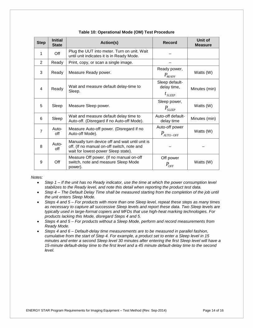
READYP
SLEEPt
SLEEPP
OFFAUTOP
OFFP
Table 10: Operational Mode (OM) Test Procedure
Step Initial State
Action(s) Record Unit of
Measure
1 Off Plug the UUT into meter. Turn on unit. Wait until unit indicates it is in Ready Mode.
–
2 Ready Print, copy, or scan a single image. –
3 Ready Measure Ready power. Ready power,
Watts (W)
4 Ready Wait and measure default delay-time to Sleep.
Sleep default-delay time, Minutes (min)
5 Sleep Measure Sleep power. Sleep power,
Watts (W)
6 Sleep Wait and measure default delay time to Auto-off. (Disregard if no Auto-off Mode).
Auto-off default-delay time
Minutes (min)
7 Auto-
off Measure Auto-off power. (Disregard if no Auto-off Mode).
Auto-off power Watts (W)
8 Auto-
off
Manually turn device off and wait until unit is off. (If no manual on-off switch, note and wait for lowest-power Sleep state).
– –
9 Off Measure Off power. (If no manual on-off switch, note and measure Sleep Mode power).
Off power Watts (W)
Notes:
Step 1 – If the unit has no Ready indicator, use the time at which the power consumption level stabilizes to the Ready level, and note this detail when reporting the product test data.
Step 4 – The Default Delay Time shall be measured starting from the completion of the job until the unit enters Sleep Mode.
Steps 4 and 5 – For products with more than one Sleep level, repeat these steps as many times as necessary to capture all successive Sleep levels and report these data. Two Sleep levels are typically used in large-format copiers and MFDs that use high-heat marking technologies. For products lacking this Mode, disregard Steps 4 and 5.
Steps 4 and 5 – For products without a Sleep Mode, perform and record measurements from Ready Mode.
Steps 4 and 6 – Default-delay time measurements are to be measured in parallel fashion, cumulative from the start of Step 4. For example, a product set to enter a Sleep level in 15 minutes and enter a second Sleep level 30 minutes after entering the first Sleep level will have a 15-minute default-delay time to the first level and a 45 minute default-delay time to the second level.
ENERGY STAR Program Requirements for Imaging Equipment – Test Method (Rev. Sep-2014) Page 14 of 16

10 TEST PROCEDURES FOR PRODUCTS WITH A DIGITAL FRONT END (DFE)
This step applies only to products that have a DFE as defined in Section 1 of the ENERGY STAR Program Requirements for Imaging Equipment.
10.1 Ready Mode DFE Test
A) Products that are network-capable as-shipped shall be connected during testing. The network connection used shall be determined using Table 6.
B) If the DFE has a separate main power cord, regardless of whether the cord and controller are internal or external to the imaging product, a 10 minute power measurement of the DFE alone shall be made, and the average power recorded while the main product is in Ready Mode.
C) If the DFE does not have a separate main power cord, the tester shall measure the dc power required for the DFE when the unit as a whole is in Ready Mode. A 10 minute power measurement of the dc input to the DFE shall be made, and the average power recorded while the main product is in Ready Mode. This will most commonly be accomplished by taking an instantaneous power measurement of the dc input to the DFE.
10.2 Sleep Mode DFE Test
This testing shall be performed to obtain the Sleep Mode power of a DFE device over a 1 hour period. The resulting value will be used to qualify Imaging Equipment products that incorporate DFEs with network-capable Sleep Modes.
A) Products that are network-capable as-shipped shall be connected during testing. The network connection used shall be determined using Table 6.
B) If the DFE has a separate main power cord, regardless of whether the cord and controller are internal or external to the imaging product, a 1 hour power measurement of the DFE alone shall be made, and the average power recorded while the main product is in Sleep Mode. At the end of the 1 hour power measurement, a print job shall be sent to the main product to ensure the DFE is responsive.
C) If the DFE does not have a separate main power cord, the tester shall measure the dc power required for the DFE when the unit as a whole is in Sleep Mode. A 1 hour power measurement of the dc input to the DFE shall be made, and the average power recorded while the main product is in Sleep Mode. At the end of the 1 hour power measurement, a print job shall be sent to the main product to ensure the DFE is responsive.
D) In cases B) and C), the following requirements apply:
1) Manufacturers shall provide information on:
a) Whether DFE Sleep Mode is enabled as-shipped; and
b) The expected time to sleep of the DFE.
2) If the DFE does not respond to the print request at the end of 1 hour, the Ready Mode power level measured in the test method shall be reported as the Sleep Mode power.
Note: All information specified or provided by manufacturers for product testing shall be publicly available.
11 REFERENCES
A) ISO/IEC 10561:1999. Information technology — Office equipment — Printing devices — Method for measuring throughput — Class 1 and Class 2 printers.
B) IEC 62301:2011 . Household Electrical Appliances – Measurement of Standby Power. Ed. 2.0.
ENERGY STAR Program Requirements for Imaging Equipment – Test Method (Rev. Sep-2014) Page 15 of 16
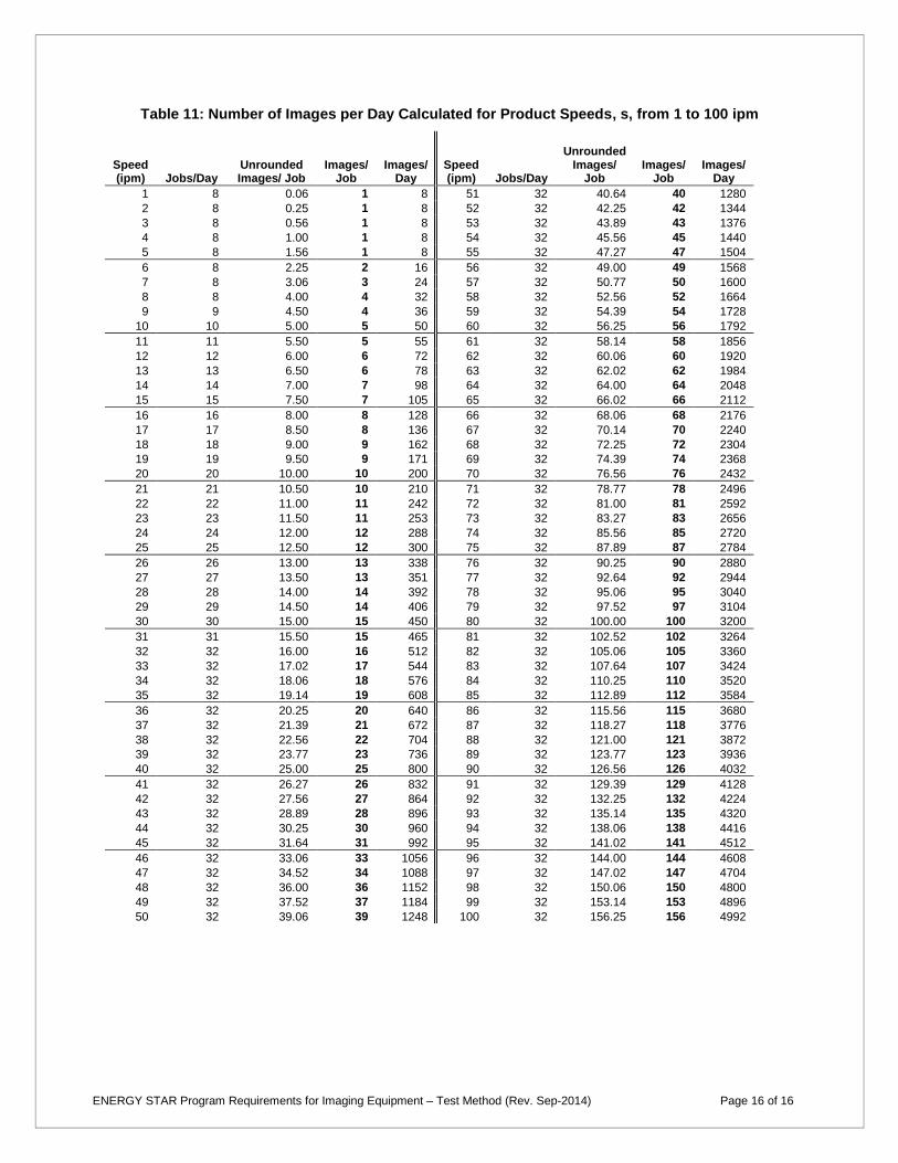
Table 11: Number of Images per Day Calculated for Product Speeds, s, from 1 to 100 ipm
Unrounded Speed Unrounded Images/ Images/ Speed Images/ Images/ Images/ (ipm) Jobs/Day Images/ Job Job Day (ipm) Jobs/Day Job Job Day
1 8 0.06 1 8 51 32 40.64 40 1280
2 8 0.25 1 8 52 32 42.25 42 1344
3 8 0.56 1 8 53 32 43.89 43 1376
4 8 1.00 1 8 54 32 45.56 45 1440
5 8 1.56 1 8 55 32 47.27 47 1504
6 8 2.25 2 16 56 32 49.00 49 1568
7 8 3.06 3 24 57 32 50.77 50 1600
8 8 4.00 4 32 58 32 52.56 52 1664
9 9 4.50 4 36 59 32 54.39 54 1728
10 10 5.00 5 50 60 32 56.25 56 1792
11 11 5.50 5 55 61 32 58.14 58 1856
12 12 6.00 6 72 62 32 60.06 60 1920
13 13 6.50 6 78 63 32 62.02 62 1984
14 14 7.00 7 98 64 32 64.00 64 2048
15 15 7.50 7 105 65 32 66.02 66 2112
16 16 8.00 8 128 66 32 68.06 68 2176
17 17 8.50 8 136 67 32 70.14 70 2240
18 18 9.00 9 162 68 32 72.25 72 2304
19 19 9.50 9 171 69 32 74.39 74 2368
20 20 10.00 10 200 70 32 76.56 76 2432
21 21 10.50 10 210 71 32 78.77 78 2496
22 22 11.00 11 242 72 32 81.00 81 2592
23 23 11.50 11 253 73 32 83.27 83 2656
24 24 12.00 12 288 74 32 85.56 85 2720
25 25 12.50 12 300 75 32 87.89 87 2784
26 26 13.00 13 338 76 32 90.25 90 2880
27 27 13.50 13 351 77 32 92.64 92 2944
28 28 14.00 14 392 78 32 95.06 95 3040
29 29 14.50 14 406 79 32 97.52 97 3104
30 30 15.00 15 450 80 32 100.00 100 3200
31 31 15.50 15 465 81 32 102.52 102 3264
32 32 16.00 16 512 82 32 105.06 105 3360
33 32 17.02 17 544 83 32 107.64 107 3424
34 32 18.06 18 576 84 32 110.25 110 3520
35 32 19.14 19 608 85 32 112.89 112 3584
36 32 20.25 20 640 86 32 115.56 115 3680
37 32 21.39 21 672 87 32 118.27 118 3776
38 32 22.56 22 704 88 32 121.00 121 3872
39 32 23.77 23 736 89 32 123.77 123 3936
40 32 25.00 25 800 90 32 126.56 126 4032
41 32 26.27 26 832 91 32 129.39 129 4128
42 32 27.56 27 864 92 32 132.25 132 4224
43 32 28.89 28 896 93 32 135.14 135 4320
44 32 30.25 30 960 94 32 138.06 138 4416
45 32 31.64 31 992 95 32 141.02 141 4512
46 32 33.06 33 1056 96 32 144.00 144 4608
47 32 34.52 34 1088 97 32 147.02 147 4704
48 32 36.00 36 1152 98 32 150.06 150 4800
49 32 37.52 37 1184 99 32 153.14 153 4896
50 32 39.06 39 1248 100 32 156.25 156 4992
ENERGY STAR Program Requirements for Imaging Equipment – Test Method (Rev. Sep-2014) Page 16 of 16