Embed Size (px)
Citation preview
IEEE COMMUNICATIONS SURVEYS & TUTORIALS, VOL. 13, NO. 3, THIRD QUARTER 2011 443
Energy Harvesting Sensor Nodes: Survey andImplications
Sujesha Sudevalayam and Purushottam Kulkarni
Abstract—Sensor networks with battery-powered nodes canseldom simultaneously meet the design goals of lifetime, cost,sensing reliability and sensing and transmission coverage.Energy-harvesting, converting ambient energy to electrical en-ergy, has emerged as an alternative to power sensor nodes.By exploiting recharge opportunities and tuning performanceparameters based on current and expected energy levels, en-ergy harvesting sensor nodes have the potential to address theconflicting design goals of lifetime and performance. This papersurveys various aspects of energy harvesting sensor systems—architecture, energy sources and storage technologies and exam-ples of harvesting-based nodes and applications. The study alsodiscusses the implications of recharge opportunities on sensornode operation and design of sensor network solutions.
Index Terms—Sensor networks, Energy-aware systems, Energyharvesting.
I. INTRODUCTION
A SENSOR network, a network of collaborating embeddeddevices (sensor nodes) with capabilities of sensing, com-
putation and communication, is used to sense and collect datafor application specific analysis. A sensor network applicationhas several design dimensions, sensing modality, sensor nodecomputation, communication and storage capabilities, cost andsize of each node, type of power source, architecture fordeployment, protocols for data dissemination and communi-cation, applications and management tools, to name a few.A typical and widely deployed application category is onethat uses battery-powered sensor nodes. A few instantiationsof such applications are, Habitat monitoring [1], Volcanomonitoring [2], Structural monitoring [3], [4] and Vehicletracking [5]. Untethered sensor nodes used in these deploy-ments facilitate mobility and deployment in hard-to-reachlocations.A major limitation of untethered nodes is finite battery
capacity—nodes will operate for a finite duration, only aslong as the battery lasts. Finite node lifetime implies finitelifetime of the applications or additional cost and complexityto regularly change batteries. Nodes could possibly use largebatteries for longer lifetimes, but will have to deal withincreased size, weight and cost. Nodes may also opt to uselow-power hardware like a low-power processor and radio, atthe cost of lesser computation ability and lower transmissionranges.
Manuscript received 20 December 2008; revised 23 June, 2009, 6 October2009, 30 January 2010, and 17 March 2010.S. Sudevalayam and P. Kulkarni are with the Department of Computer
Science and Engineering, Indian Institute of Technology Bombay, Mumbai,India, 400076 (e-mail: {sujesha, puru}@cse.iitb.ac.in).Digital Object Identifier 10.1109/SURV.2011.060710.00094
Several solution techniques have been proposed to max-imize the lifetime of battery-powered sensor nodes. Someof these include energy-aware MAC protocols (SMAC [6],BMAC [7], XMAC [8]), power aware storage, routing anddata dissemination protocols [9], [10], [11], duty-cyclingstrategies [12], [13], adaptive sensing rate [14], tiered systemarchitectures [15], [16], [17] and redundant placement ofnodes [18], [19]. While all the above techniques optimize andadapt energy usage to maximize the lifetime of a sensor node,the lifetime remains bounded and finite. The above techniqueshelp prolong the application lifetime and/or the time intervalbetween battery replacements but do not preclude energy-related inhibitions. With a finite energy source, seldom canall the performance parameters be optimized simultaneously,e.g., higher battery capacity implies increased cost, low duty-cycle implies decreased sensing reliability, higher transmissionrange implies higher power requirement and lower transmis-sion range implies transmission paths with more number ofhops resulting in energy usage at more number of nodes.
An alternative technique that has been applied to addressthe problem of finite node lifetime is the use of energyharvesting. Energy harvesting refers to harnessing energy fromthe environment or other energy sources (body heat, footstrike, finger strokes) and converting it to electrical energy.The harnessed electrical energy powers the sensor nodes. If theharvested energy source is large and periodically/continuouslyavailable, a sensor node can be powered perpetually. Further,based on the periodicity and magnitude of harvestable energy,system parameters of a node can be tuned to increase nodeand network performance. Since a node is energy-limited onlytill the next harvesting opportunity (recharge cycle), it canoptimize its energy usage to maximize performance duringthat interval. For example, a node can increase its samplingfrequency or its duty-cycle to increase sensing reliability, orincrease transmission power to decrease length of routingpaths.
As a result, energy harvesting techniques have the potentialto address the tradeoff between performance parameters andlifetime of sensor nodes. The challenge lies in estimatingthe periodicity and magnitude of the harvestable source anddeciding which parameters to tune and simultaneously avoidpremature energy depletion before the next recharge cycle.
As part of this study, we present details of energy harvestingtechniques—architectures, energy sources, storage technolo-gies and examples of applications and network deployments.Further, as mentioned above, sensor nodes can exploit energyharvesting opportunities to dynamically tune system param-eters. These adaptations have interesting implications on the
1553-877X/11/$25.00 c© 2011 IEEE
444 IEEE COMMUNICATIONS SURVEYS & TUTORIALS, VOL. 13, NO. 3, THIRD QUARTER 2011
design of sensor network applications and solutions, which wediscuss. As contributions of this study we present and discuss,
• basics of energy harvesting techniques,• details of energy sources used for harvesting and corre-sponding energy storage technologies,
• energy harvesting architectures,• examples of energy harvesting systems and applicationsbased on these systems and
• implications of energy harvesting on design of sensornetwork applications and solutions.
The rest of the paper is organized as follows, Section IIdescribes basic concepts, components and types of energyharvesting nodes. Examples of energy harvesting sensor nodesand related applications are presented in Section III. Sec-tion IV presents implications of harvestable energy on sensornetwork applications and solutions design. Section V con-cludes the paper.
II. ENERGY HARVESTING SENSOR NODES
Energy harvesting refers to scavenging energy or convertingenergy from one form to the other. Applied to sensor nodes,energy from external sources can be harvested to powerthe nodes and in turn, increase their lifetime and capability.Given the energy-usage profile of a node, energy harvestingtechniques could meet partial or all of its energy needs.A widespread and popular technique of energy harvestingis converting solar energy to electrical energy. Solar energyis uncontrollable—the intensity of direct sunlight cannot becontrolled—but it is a predictable energy source with dailyand seasonal patterns. Other techniques of energy harvestingconvert mechanical energy or wind energy to electrical en-ergy. For example, mechanical stress applied to piezo-electricmaterials, or to a rotating arm connected to a generator, canproduce electrical energy. Since the amount of energy usedfor conversion can be varied, such techniques can be viewedas controllable energy sources.A typical energy harvesting system has three components,
the Energy source, the Harvesting architecture and the Load.Energy source refers to the ambient source of energy to beharvested. Harvesting architecture consists of mechanisms toharness and convert the input ambient energy to electricalenergy. Load refers to the activity that consumes energy andacts as a sink for the harvested energy.
A. Energy Harvesting Architectures
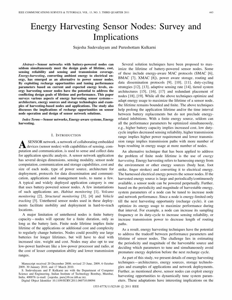
Broadly, energy harvesting can be divided into twoarchitectures— (i) Harvest-Use: Energy is harvested just-in-time for use and (ii) Harvest-Store-Use: Energy is harvestedwhenever possible and stored for future use. A similar cate-gorization is present in [20].1) Harvest-Use Architecture: Figure 1(a) shows the
Harvest-Use architecture. In this case, the harvesting systemdirectly powers the sensor node and as a result, for the nodeto be operational, the power output of the harvesting systemhas to be continuously above the minimum operating point. Ifsufficient energy is not available, the node will be disabled.Abrupt variations in harvesting capacity close to the minimum
power point will cause the sensor node to oscillate in ON andOFF states.A Harvest-Use system can be built to use mechanical energy
sources like pushing keys/buttons, walking, pedaling, etc. Forexample, the push of a key/button can be used to deform apiezo-electric material, thereby generating electrical energy tosend a short wireless message[21]. Similarly, piezo-electricmaterials strategically placed within a shoe may deform todifferent extents while walking and running. The harvestedenergy can be used to transmit RFID signals, used to trackthe shoe-wearer[22], [23], [24].2) Harvest-Store-Use Architecture: Figure 1(b) depicts the
Harvest-Store-Use architecture. The architecture consists ofa storage component that stores harvested energy and alsopowers the sensor node. Energy storage is useful when theharvested energy available is more than its current usage.Alternatively, energy can also be hoarded in storage untilenough has been collected for system operation. Energy isstored to be used later when either harvesting opportunitydoes not exist or energy usage of the sensor node has to beincreased to improve capability and performance parameters.The storage component itself may be single-stage or double-stage. Secondary storage is a backup storage for situationswhen the Primary storage is exhausted[25].As an example, a Harvest-Store-Use system can use uncon-
trolled but predictable energy sources like solar energy[25],[26], [27], [28]. During the daytime, energy is used for workand also stored for later use. During night, the stored energyis conservatively used to power the sensor node.
B. Sources of Harvestable Energy
A vital component of any energy harvesting architectureis the energy source—it dictates the amount and rate ofenergy available for use. Energy sources have different char-acteristics along the axes of controllability, predictability andmagnitude[20]. A controllable energy source can provideharvestable energy whenever required, energy availability neednot be predicted before harvesting. With non-controllableenergy sources, energy must be simply harvested wheneveravailable. In this case, if the energy source is predictablethen a prediction model which forecasts its availability canbe used to indicate the time of next recharge cycle. Further,energy sources can be broadly classified into the followingtwo categories, (i) Ambient Energy Sources: Sources of en-ergy from the surrounding environment, e.g., solar energy,wind energy and RF energy, and (ii) Human Power: Energyharvested from body movements of humans [21], [22], [23],[24]. Passive human power sources are those which are notuser controllable. Some examples are blood pressure, bodyheat and breath[24]. Active human power sources are thosethat are under user control, and the user exerts a specificforce to generate the energy for harvesting, e.g., finger motion,paddling and walking[24].
C. Energy Conversion Mechanisms
This refers to mechanisms for scavenging electrical energyfrom a given energy source. The choice of energy conversionmechanism is closely tied to the choice of energy source. In
SUDEVALAYAM and KULKARNI: ENERGY HARVESTING SENSOR NODES: SURVEY AND IMPLICATIONS 445
DIRECT FROM SOURCE
Sensor Node
Harvesting System Harvesting System
SINGLE/DOUBLE STAGE STORAGE
Sensor Node
Primary Storage Secondary Storage
(a) Harvest-Use (b) Harvest-Store-Use
Fig. 1. Energy harvesting architectures with and without storage capability.
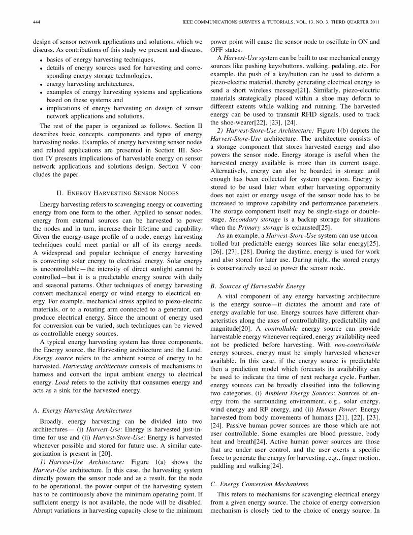
TABLE ILISTING AND CHARACTERIZATION OF ENERGY SOURCES.
Energy Characteristics Amount of Harvesting Conversion Amount ofSource Energy Technology Efficiency Energy
Available Harvested
Solar[25], [26], [27], [28] Ambient, Uncontrollable, 100mW/cm2 Solar Cells 15% 15mW/cm2
PredictableWind[28] Ambient, Uncontrollable, - Anemometer - 1200mWh/day
PredictableFinger motion[22], [24] Active human power, 19mW Piezoelectric 11% 2.1mW
Fully controllableFootfalls[22], [24] Active human power, 67W Piezoelectric 7.5% 5W
Fully controllableVibrations in indoor Ambient, Uncontrollable, - Electromagnetic - 0.2mW/cm2
environments[29] Unpredictable InductionExhalation[24] Passive human power, 1W Breath masks 40% 0.4W
Uncontrollable,Unpredictable
Breathing[24] Passive human power, 0.83W Ratchet-flywheel 50% 0.42WUncontrollable,Unpredictable
Blood Pressure[24] Passive human power, 0.93W Micro-generator 40% 0.37WUncontrollable,Unpredictable
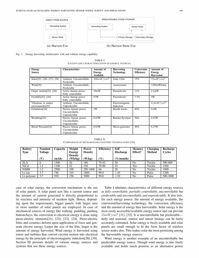
TABLE IICOMPARISON OF RECHARGEABLE BATTERY TECHNOLOGIES [26].
Battery Nominal Capacity Weight Power Efficiency Self Memory Charging RechargeType Voltage Energy Density Discharge Effect? Method Cycles
Density(V) (mAh) (Wh/kg) (W/kg) (%) (%/month)
SLA 6 1300 26 180 70-92 20 No Trickle 500-800NiCd 1.2 1100 42 150 70-90 10 Yes Trickle 1500NiMH 1.2 2500 100 250-1000 66 20 No Trickle 1000Li-ion 3.7 740 165 1800 99.9 <10 No Pulse 1200Li-polymer 3.7 930 156 3000 99.8 <10 No Pulse 500-1000
case of solar energy, the conversion mechanism is the useof solar panels. A solar panel acts like a current source andthe amount of current generated is directly proportional toits size/area and intensity of incident light. Hence, depend-ing upon the requirements, bigger panels with larger areaor more number of solar panels are employed. In case ofmechanical sources of energy like walking, paddling, pushingbuttons/keys, the conversion to electrical energy is done usingpiezo-electric elements[21], [22], [23], [24]. Piezo-electricfilms and ceramics deform upon application of force and gen-erate electric energy. Larger the size of the film, larger is theamount of energy harvested. Wind energy is harvested usingrotors and turbines that convert circular motion into electricalenergy by the principle of electromagnetic induction[28], [30].Section III presents details of various energy sources andsystems that use these energy sources.
Table I tabulates characteristics of different energy sourcesas fully controllable, partially controllable, uncontrollable butpredictable and uncontrollable and unpredictable. It also lists,for each energy source, the amount of energy available, theconversion/harvesting technology, the conversion efficiencyand the amount of energy thus harvestable. Solar energy is themost easily accessible/available energy source and can provide15mW/cm2 [31], [32]. It is uncontrollable but predictable—daily and seasonal, sunrise and sunset timings can be fairlyaccurately estimated. Solar energy is freely available and solarpanels are small enough to fit the form factor of wirelesssensor nodes also. This makes solar the most promising amongthe harvestable energy sources.Wind energy is another example of an uncontrollable but
predictable energy source. Though wind energy is also freelyavailable and holds much promise as an alternative power
446 IEEE COMMUNICATIONS SURVEYS & TUTORIALS, VOL. 13, NO. 3, THIRD QUARTER 2011
source (1200mWh/day), the turbines and wind generatorsare bulkier than desirable. Pushing a button to cause vibrationof piezo-electric material[21], and thus generating energy isan example of a controllable source. Here, the button can bepushed at will, to generate energy. Such active human powersources like finger motion and footfalls are useful to powersmall electronic devices but their use would be restricted to do-mestic/local uses and may not apply to remote wireless sensornetwork deployments. Similarly, passive human power sourceslike body heat, exhalation, breathing and blood pressure givesizeable amounts of power in the order of a few hundredmW ,but they can be inconvenient and burdensome to the humanbody.No single energy source is ideal for all applications. The
choice depends on every application’s requirements and con-straints. In the following sections, we will see different sensornode prototypes that harvest energy from sources like solar,finger motion and footfalls.
D. Storage Technologies
Storage technology plays an important role in energy har-vesting systems and, as a consequence, the choice of thestorage component and recharge technology is of prime sig-nificance. Rechargeable batteries, a common choice of energystorage, can be made up of any one of several technologies(chemical compositions). A rechargeable battery is a storagecell that can be charged by reversing the internal chemicalreaction. A few popular rechargeable technologies are SealedLead Acid (SLA), Nickel Cadmium (NiCd), Nickel MetalHydride (NiMH) and Lithium Ion (Li-ion). These batterytechnologies can be characterized along several axes — en-ergy density, power density, charge-discharge efficiency1, self-discharge rate and number of deep recharge cycles2.Table II shows typical values of the above parameters across
different battery technologies. Nominal voltages for SLA,NiCd, NiMH and Li-ion batteries are 6 volts, 1.2 volts, 1.2volts and 3.7 volts, respectively. Table II shows that Lithiumion batteries have highest output voltage, energy density,power density and charge-discharge efficiency. They also havelow self-discharge rate3. Though NiMH batteries have betterenergy density and power density than NiCd batteries, NiCdbatteries have higher number of deep recharge cycles. SealedLead Acid batteries have the lowest values for energy density,power and number of cycles and hence is the least effectivestorage technology.Two storage technologies, NiMH and Li-based, emerge
as good choices for energy harvesting nodes. Lithium bat-teries have high output voltage, energy density, efficiencyand moderately low self-discharge rate. They do not sufferfrom memory effect—loss of energy capacity due to repeatedshallow recharge4. However, Lithium batteries require pulse-charging for recharge—a high pulsating charging current.
1Charge-discharge efficiency is the ratio of energy stored into the batteryto the energy delivered to the battery2Deep recharge cycle refers to the cycle of recharging the battery after a
complete drain-out3Self-discharge is the loss of battery capacity while it simply sits on the
shelf.4Shallow recharge refers to recharging a partially discharged battery.
Usually an auxiliary battery or a charging circuit is requiredfor this purpose. On the other hand, NiMH batteries can betrickle charged, i.e., directly connected to an energy source forcharging, and do not need complex pulse charging circuits.They have reasonably high energy, power density and numberof recharge cycles. Though NiMH batteries do suffer frommemory effect, the effect is reversible by conditioning—fully discharging the battery after charging it. Additionally,the charge-discharge efficiency of NiMH batteries is lowerthan Lithium-based batteries. As can be seen, both storagetechnologies have pros and cons and the choice depends onthe tradeoff dictated by the application requirements and con-straints. In the following sections, we will present examplesof prototype nodes that use both NiMH and Lithium batteriesfor different requirements and deployment conditions.Alternatively, super-capacitors can be used as storage com-
ponents instead of, or along with, rechargeable batteries. Likebatteries, super-capacitors also store charge, but they self-discharge at a much higher rate than batteries, as much as5.9% per day[26]. Additionally, a super-capacitor’s weight-to-energy density is very low, only 5Wh/kg as comparedto 100Wh/kg of NiMH batteries. However, super-capacitorshave high charge-discharge efficiency (97− 98%) and also donot suffer from memory effect. Super-capacitors can also betrickle-charged like NiMH batteries and hence do not needcomplex charging circuitry. Theoretically, super-capacitorshave infinite recharge cycles, and therefore have no limit to thenumber of times they can undergo deep recharge[25]. Thus,super-capacitors are useful storage elements in locations whereample energy is available at regular intervals. They can alsobe used to buffer the available energy if the energy source isjittery, i.e., the super-capacitor is trickle charged and a stabledischarge from the capacitor charges the battery.
III. ENERGY HARVESTING SENSOR NODES ANDAPPLICATIONS
This section describes implementations of energy harvestingsensor nodes and applications designed to use various energysources such as solar energy [20], [25], [27], [28], [33], [34],[35], active user power [21], [22], [23], [24], [36], windenergy [28], [30] and RF energy [37], [38], [39], [40], [41],[42].
A. Solar Energy Harvesting Systems
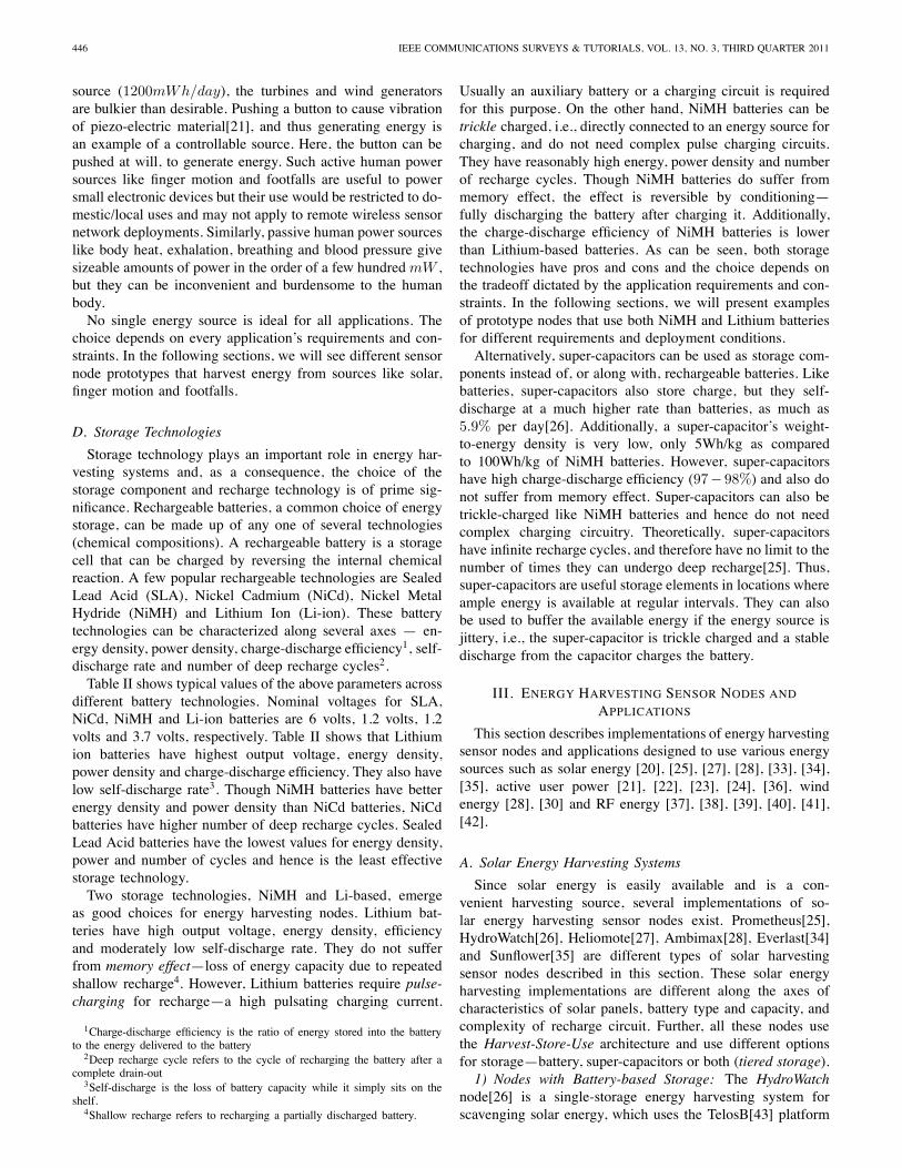
Since solar energy is easily available and is a con-venient harvesting source, several implementations of so-lar energy harvesting sensor nodes exist. Prometheus[25],HydroWatch[26], Heliomote[27], Ambimax[28], Everlast[34]and Sunflower[35] are different types of solar harvestingsensor nodes described in this section. These solar energyharvesting implementations are different along the axes ofcharacteristics of solar panels, battery type and capacity, andcomplexity of recharge circuit. Further, all these nodes usethe Harvest-Store-Use architecture and use different optionsfor storage—battery, super-capacitors or both (tiered storage).1) Nodes with Battery-based Storage: The HydroWatch
node[26] is a single-storage energy harvesting system forscavenging solar energy, which uses the TelosB[43] platform
SUDEVALAYAM and KULKARNI: ENERGY HARVESTING SENSOR NODES: SURVEY AND IMPLICATIONS 447
Solar Panel
Regulator RegulatorOutput
StorageEnergy
Load
Input (Optional)
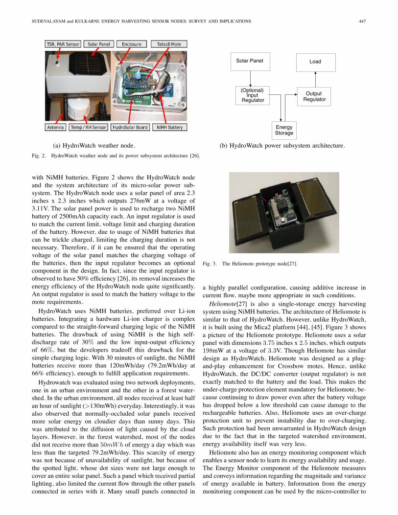
(a) HydroWatch weather node. (b) HydroWatch power subsystem architecture.
Fig. 2. HydroWatch weather node and its power subsystem architecture [26].
with NiMH batteries. Figure 2 shows the HydroWatch nodeand the system architecture of its micro-solar power sub-system. The HydroWatch node uses a solar panel of area 2.3inches x 2.3 inches which outputs 276mW at a voltage of3.11V. The solar panel power is used to recharge two NiMHbattery of 2500mAh capacity each. An input regulator is usedto match the current limit, voltage limit and charging durationof the battery. However, due to usage of NiMH batteries thatcan be trickle charged, limiting the charging duration is notnecessary. Therefore, if it can be ensured that the operatingvoltage of the solar panel matches the charging voltage ofthe batteries, then the input regulator becomes an optionalcomponent in the design. In fact, since the input regulator isobserved to have 50% efficiency [26], its removal increases theenergy efficiency of the HydroWatch node quite significantly.An output regulator is used to match the battery voltage to themote requirements.
HydroWatch uses NiMH batteries, preferred over Li-ionbatteries. Integrating a hardware Li-ion charger is complexcompared to the straight-forward charging logic of the NiMHbatteries. The drawback of using NiMH is the high self-discharge rate of 30% and the low input-output efficiencyof 66%, but the developers tradeoff this drawback for thesimple charging logic. With 30 minutes of sunlight, the NiMHbatteries receive more than 120mWh/day (79.2mWh/day at66% efficiency), enough to fulfill application requirements.
Hydrowatch was evaluated using two network deployments,one in an urban environment and the other in a forest water-shed. In the urban environment, all nodes received at least halfan hour of sunlight (>130mWh) everyday. Interestingly, it wasalso observed that normally-occluded solar panels receivedmore solar energy on cloudier days than sunny days. Thiswas attributed to the diffusion of light caused by the cloudlayers. However, in the forest watershed, most of the nodesdid not receive more than 50mWh of energy a day which wasless than the targeted 79.2mWh/day. This scarcity of energywas not because of unavailability of sunlight, but because ofthe spotted light, whose dot sizes were not large enough tocover an entire solar panel. Such a panel which received partiallighting, also limited the current flow through the other panelsconnected in series with it. Many small panels connected in
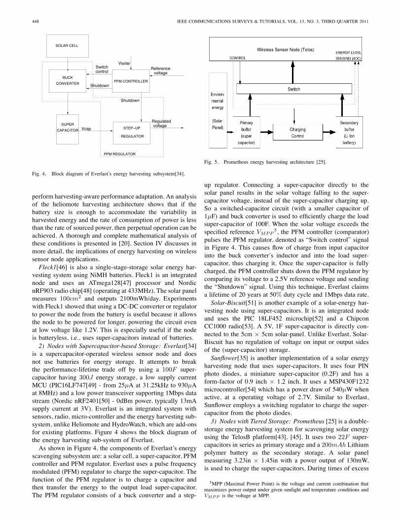
Fig. 3. The Heliomote prototype node[27].
a highly parallel configuration, causing additive increase incurrent flow, maybe more appropriate in such conditions.Heliomote[27] is also a single-storage energy harvesting
system using NiMH batteries. The architecture of Heliomote issimilar to that of HydroWatch. However, unlike HydroWatch,it is built using the Mica2 platform [44], [45]. Figure 3 showsa picture of the Heliomote prototype. Heliomote uses a solarpanel with dimensions 3.75 inches x 2.5 inches, which outputs198mW at a voltage of 3.3V. Though Heliomote has similardesign as HydroWatch, Heliomote was designed as a plug-and-play enhancement for Crossbow motes. Hence, unlikeHydroWatch, the DC/DC converter (output regulator) is notexactly matched to the battery and the load. This makes theunder-charge protection element mandatory for Heliomote, be-cause continuing to draw power even after the battery voltagehas dropped below a low threshold can cause damage to therechargeable batteries. Also, Heliomote uses an over-chargeprotection unit to prevent instability due to over-charging.Such protection had been unwarranted in HydroWatch designdue to the fact that in the targeted watershed environment,energy availability itself was very less.Heliomote also has an energy monitoring component which
enables a sensor node to learn its energy availability and usage.The Energy Monitor component of the Heliomote measuresand conveys information regarding the magnitude and varianceof energy available in battery. Information from the energymonitoring component can be used by the micro-controller to
448 IEEE COMMUNICATIONS SURVEYS & TUTORIALS, VOL. 13, NO. 3, THIRD QUARTER 2011
controlSwitch
Shutdown
voltageReference
voltageRegulated
CONVERTER
BUCKPFM CONTROLLER
STEP−UP
PFM REGULATOR
REGULATOR
Shutdown
Vsolar
CAPACITOR
SUPERVcap
SOLAR CELL
Fig. 4. Block diagram of Everlast’s energy harvesting subsystem[34].
perform harvesting-aware performance adaptation. An analysisof the heliomote harvesting architecture shows that if thebattery size is enough to accommodate the variability inharvested energy and the rate of consumption of power is lessthan the rate of sourced power, then perpetual operation can beachieved. A thorough and complete mathematical analysis ofthese conditions is presented in [20]. Section IV discusses inmore detail, the implications of energy harvesting on wirelesssensor node applications.Fleck1[46] is also a single-stage-storage solar energy har-
vesting system using NiMH batteries. Fleck1 is an integratednode and uses an ATmega128[47] processor and NordicnRF903 radio chip[48] (operating at 433MHz). The solar panelmeasures 100cm2 and outputs 2100mWh/day. Experimentswith Fleck1 showed that using a DC-DC converter or regulatorto power the node from the battery is useful because it allowsthe node to be powered for longer, powering the circuit evenat low voltage like 1.2V. This is especially useful if the nodeis batteryless, i.e., uses super-capacitors instead of batteries.2) Nodes with Supercapacitor-based Storage: Everlast[34]
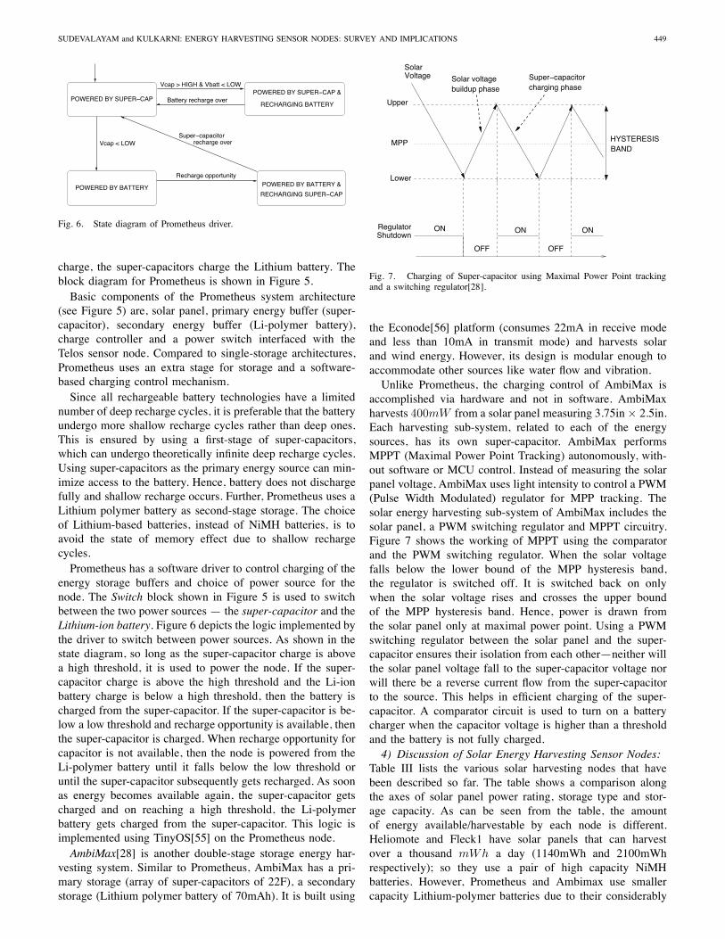
is a supercapacitor-operated wireless sensor node and doesnot use batteries for energy storage. It attempts to breakthe performance-lifetime trade off by using a 100F super-capacitor having 300J energy storage, a low supply currentMCU (PIC16LF747[49] - from 25μA at 31.25kHz to 930μAat 8MHz) and a low power transceiver supporting 1Mbps datastream (Nordic nRF2401[50] - 0dBm power, typically 13mAsupply current at 3V). Everlast is an integrated system withsensors, radio, micro-controller and the energy harvesting sub-system, unlike Heliomote and HydroWatch, which are add-onsfor existing platforms. Figure 4 shows the block diagram ofthe energy harvesting sub-system of Everlast.As shown in Figure 4, the components of Everlast’s energy
scavenging subsystem are: a solar cell, a super-capacitor, PFMcontroller and PFM regulator. Everlast uses a pulse frequencymodulated (PFM) regulator to charge the super-capacitor. Thefunction of the PFM regulator is to charge a capacitor andthen transfer the energy to the output load super-capacitor.The PFM regulator consists of a buck converter and a step-
Fig. 5. Prometheus energy harvesting architecture [25].
up regulator. Connecting a super-capacitor directly to thesolar panel results in the solar voltage falling to the super-capacitor voltage, instead of the super-capacitor charging up.So a switched-capacitor circuit (with a smaller capacitor of1μF) and buck converter is used to efficiently charge the loadsuper-capacitor of 100F. When the solar voltage exceeds thespecified reference VMPP
5, the PFM controller (comparator)pulses the PFM regulator, denoted as “Switch control” signalin Figure 4. This causes flow of charge from input capacitorinto the buck converter’s inductor and into the load super-capacitor, thus charging it. Once the super-capacitor is fullycharged, the PFM controller shuts down the PFM regulator bycomparing its voltage to a 2.5V reference voltage and sendingthe “Shutdown” signal. Using this technique, Everlast claimsa lifetime of 20 years at 50% duty cycle and 1Mbps data rate.Solar-Biscuit[51] is another example of a solar-energy har-
vesting node using super-capacitors. It is an integrated nodeand uses the PIC 18LF452 microchip[52] and a ChipconCC1000 radio[53]. A 5V, 1F super-capacitor is directly con-nected to the 5cm × 5cm solar-panel. Unlike Everlast, Solar-Biscuit has no regulation of voltage on input or output sidesof the (super-capacitor) storage.Sunflower[35] is another implementation of a solar energy
harvesting node that uses super-capacitors. It uses four PINphoto diodes, a miniature super-capacitor (0.2F) and has aform-factor of 0.9 inch × 1.2 inch. It uses a MSP430F1232microcontroller[54] which has a power draw of 540μW whenactive, at a operating voltage of 2.7V. Similar to Everlast,Sunflower employs a switching regulator to charge the super-capacitor from the photo diodes.3) Nodes with Tiered Storage: Prometheus [25] is a double-
storage energy harvesting system for scavenging solar energyusing the TelosB platform[43], [45]. It uses two 22F super-capacitors in series as primary storage and a 200mAh Lithiumpolymer battery as the secondary storage. A solar panelmeasuring 3.23in × 1.45in with a power output of 130mW,is used to charge the super-capacitors. During times of excess
5MPP (Maximal Power Point) is the voltage and current combination thatmaximizes power output under given sunlight and temperature conditions andVMPP is the voltage at MPP.
SUDEVALAYAM and KULKARNI: ENERGY HARVESTING SENSOR NODES: SURVEY AND IMPLICATIONS 449
POWERED BY BATTERY POWERED BY BATTERY &
RECHARGING SUPER−CAP
Battery recharge over
Vcap > HIGH & Vbatt < LOWPOWERED BY SUPER−CAP &
RECHARGING BATTERYPOWERED BY SUPER−CAP
Super−capacitorrecharge overVcap < LOW
Recharge opportunity
Fig. 6. State diagram of Prometheus driver.
charge, the super-capacitors charge the Lithium battery. Theblock diagram for Prometheus is shown in Figure 5.Basic components of the Prometheus system architecture
(see Figure 5) are, solar panel, primary energy buffer (super-capacitor), secondary energy buffer (Li-polymer battery),charge controller and a power switch interfaced with theTelos sensor node. Compared to single-storage architectures,Prometheus uses an extra stage for storage and a software-based charging control mechanism.Since all rechargeable battery technologies have a limited
number of deep recharge cycles, it is preferable that the batteryundergo more shallow recharge cycles rather than deep ones.This is ensured by using a first-stage of super-capacitors,which can undergo theoretically infinite deep recharge cycles.Using super-capacitors as the primary energy source can min-imize access to the battery. Hence, battery does not dischargefully and shallow recharge occurs. Further, Prometheus uses aLithium polymer battery as second-stage storage. The choiceof Lithium-based batteries, instead of NiMH batteries, is toavoid the state of memory effect due to shallow rechargecycles.Prometheus has a software driver to control charging of the
energy storage buffers and choice of power source for thenode. The Switch block shown in Figure 5 is used to switchbetween the two power sources — the super-capacitor and theLithium-ion battery. Figure 6 depicts the logic implemented bythe driver to switch between power sources. As shown in thestate diagram, so long as the super-capacitor charge is abovea high threshold, it is used to power the node. If the super-capacitor charge is above the high threshold and the Li-ionbattery charge is below a high threshold, then the battery ischarged from the super-capacitor. If the super-capacitor is be-low a low threshold and recharge opportunity is available, thenthe super-capacitor is charged. When recharge opportunity forcapacitor is not available, then the node is powered from theLi-polymer battery until it falls below the low threshold oruntil the super-capacitor subsequently gets recharged. As soonas energy becomes available again, the super-capacitor getscharged and on reaching a high threshold, the Li-polymerbattery gets charged from the super-capacitor. This logic isimplemented using TinyOS[55] on the Prometheus node.AmbiMax[28] is another double-stage storage energy har-
vesting system. Similar to Prometheus, AmbiMax has a pri-mary storage (array of super-capacitors of 22F), a secondarystorage (Lithium polymer battery of 70mAh). It is built using
Super−capacitorcharging phase
OFF OFF
ON ON ON
Upper
Lower
MPP
RegulatorShutdown
HYSTERESISBAND
VoltageSolar
buildup phaseSolar voltage
Fig. 7. Charging of Super-capacitor using Maximal Power Point trackingand a switching regulator[28].
the Econode[56] platform (consumes 22mA in receive modeand less than 10mA in transmit mode) and harvests solarand wind energy. However, its design is modular enough toaccommodate other sources like water flow and vibration.Unlike Prometheus, the charging control of AmbiMax is
accomplished via hardware and not in software. AmbiMaxharvests 400mW from a solar panel measuring 3.75in× 2.5in.Each harvesting sub-system, related to each of the energysources, has its own super-capacitor. AmbiMax performsMPPT (Maximal Power Point Tracking) autonomously, with-out software or MCU control. Instead of measuring the solarpanel voltage, AmbiMax uses light intensity to control a PWM(Pulse Width Modulated) regulator for MPP tracking. Thesolar energy harvesting sub-system of AmbiMax includes thesolar panel, a PWM switching regulator and MPPT circuitry.Figure 7 shows the working of MPPT using the comparatorand the PWM switching regulator. When the solar voltagefalls below the lower bound of the MPP hysteresis band,the regulator is switched off. It is switched back on onlywhen the solar voltage rises and crosses the upper boundof the MPP hysteresis band. Hence, power is drawn fromthe solar panel only at maximal power point. Using a PWMswitching regulator between the solar panel and the super-capacitor ensures their isolation from each other—neither willthe solar panel voltage fall to the super-capacitor voltage norwill there be a reverse current flow from the super-capacitorto the source. This helps in efficient charging of the super-capacitor. A comparator circuit is used to turn on a batterycharger when the capacitor voltage is higher than a thresholdand the battery is not fully charged.4) Discussion of Solar Energy Harvesting Sensor Nodes:
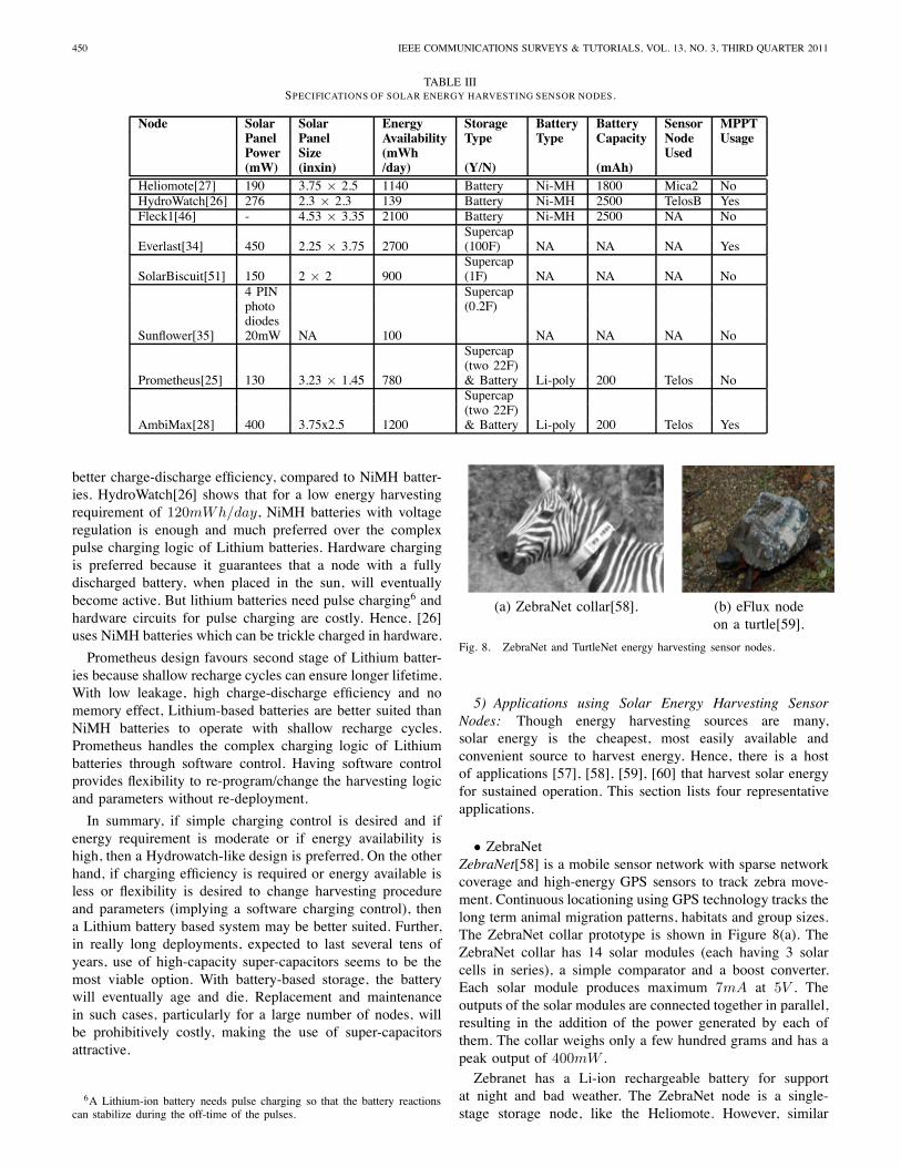
Table III lists the various solar harvesting nodes that havebeen described so far. The table shows a comparison alongthe axes of solar panel power rating, storage type and stor-age capacity. As can be seen from the table, the amountof energy available/harvestable by each node is different.Heliomote and Fleck1 have solar panels that can harvestover a thousand mWh a day (1140mWh and 2100mWhrespectively); so they use a pair of high capacity NiMHbatteries. However, Prometheus and Ambimax use smallercapacity Lithium-polymer batteries due to their considerably
450 IEEE COMMUNICATIONS SURVEYS & TUTORIALS, VOL. 13, NO. 3, THIRD QUARTER 2011
TABLE IIISPECIFICATIONS OF SOLAR ENERGY HARVESTING SENSOR NODES.
Node Solar Solar Energy Storage Battery Battery Sensor MPPTPanel Panel Availability Type Type Capacity Node UsagePower Size (mWh Used(mW) (inxin) /day) (Y/N) (mAh)
Heliomote[27] 190 3.75 × 2.5 1140 Battery Ni-MH 1800 Mica2 NoHydroWatch[26] 276 2.3 × 2.3 139 Battery Ni-MH 2500 TelosB YesFleck1[46] - 4.53 × 3.35 2100 Battery Ni-MH 2500 NA No
SupercapEverlast[34] 450 2.25 × 3.75 2700 (100F) NA NA NA Yes
SupercapSolarBiscuit[51] 150 2 × 2 900 (1F) NA NA NA No
4 PIN Supercapphoto (0.2F)diodes
Sunflower[35] 20mW NA 100 NA NA NA NoSupercap(two 22F)
Prometheus[25] 130 3.23 × 1.45 780 & Battery Li-poly 200 Telos NoSupercap(two 22F)
AmbiMax[28] 400 3.75x2.5 1200 & Battery Li-poly 200 Telos Yes
better charge-discharge efficiency, compared to NiMH batter-ies. HydroWatch[26] shows that for a low energy harvestingrequirement of 120mWh/day, NiMH batteries with voltageregulation is enough and much preferred over the complexpulse charging logic of Lithium batteries. Hardware chargingis preferred because it guarantees that a node with a fullydischarged battery, when placed in the sun, will eventuallybecome active. But lithium batteries need pulse charging6 andhardware circuits for pulse charging are costly. Hence, [26]uses NiMH batteries which can be trickle charged in hardware.
Prometheus design favours second stage of Lithium batter-ies because shallow recharge cycles can ensure longer lifetime.With low leakage, high charge-discharge efficiency and nomemory effect, Lithium-based batteries are better suited thanNiMH batteries to operate with shallow recharge cycles.Prometheus handles the complex charging logic of Lithiumbatteries through software control. Having software controlprovides flexibility to re-program/change the harvesting logicand parameters without re-deployment.
In summary, if simple charging control is desired and ifenergy requirement is moderate or if energy availability ishigh, then a Hydrowatch-like design is preferred. On the otherhand, if charging efficiency is required or energy available isless or flexibility is desired to change harvesting procedureand parameters (implying a software charging control), thena Lithium battery based system may be better suited. Further,in really long deployments, expected to last several tens ofyears, use of high-capacity super-capacitors seems to be themost viable option. With battery-based storage, the batterywill eventually age and die. Replacement and maintenancein such cases, particularly for a large number of nodes, willbe prohibitively costly, making the use of super-capacitorsattractive.
6A Lithium-ion battery needs pulse charging so that the battery reactionscan stabilize during the off-time of the pulses.
(a) ZebraNet collar[58]. (b) eFlux nodeon a turtle[59].
Fig. 8. ZebraNet and TurtleNet energy harvesting sensor nodes.
5) Applications using Solar Energy Harvesting SensorNodes: Though energy harvesting sources are many,solar energy is the cheapest, most easily available andconvenient source to harvest energy. Hence, there is a hostof applications [57], [58], [59], [60] that harvest solar energyfor sustained operation. This section lists four representativeapplications.
• ZebraNetZebraNet[58] is a mobile sensor network with sparse networkcoverage and high-energy GPS sensors to track zebra move-ment. Continuous locationing using GPS technology tracks thelong term animal migration patterns, habitats and group sizes.The ZebraNet collar prototype is shown in Figure 8(a). TheZebraNet collar has 14 solar modules (each having 3 solarcells in series), a simple comparator and a boost converter.Each solar module produces maximum 7mA at 5V . Theoutputs of the solar modules are connected together in parallel,resulting in the addition of the power generated by each ofthem. The collar weighs only a few hundred grams and has apeak output of 400mW .Zebranet has a Li-ion rechargeable battery for support
at night and bad weather. The ZebraNet node is a single-stage storage node, like the Heliomote. However, similar
SUDEVALAYAM and KULKARNI: ENERGY HARVESTING SENSOR NODES: SURVEY AND IMPLICATIONS 451
Client Client
Trio Gateways
Trio Nodes
Root Server
(a) Trio system hardware architecture. (b) Trio node (c) Trio gateway.mounted on tripod.
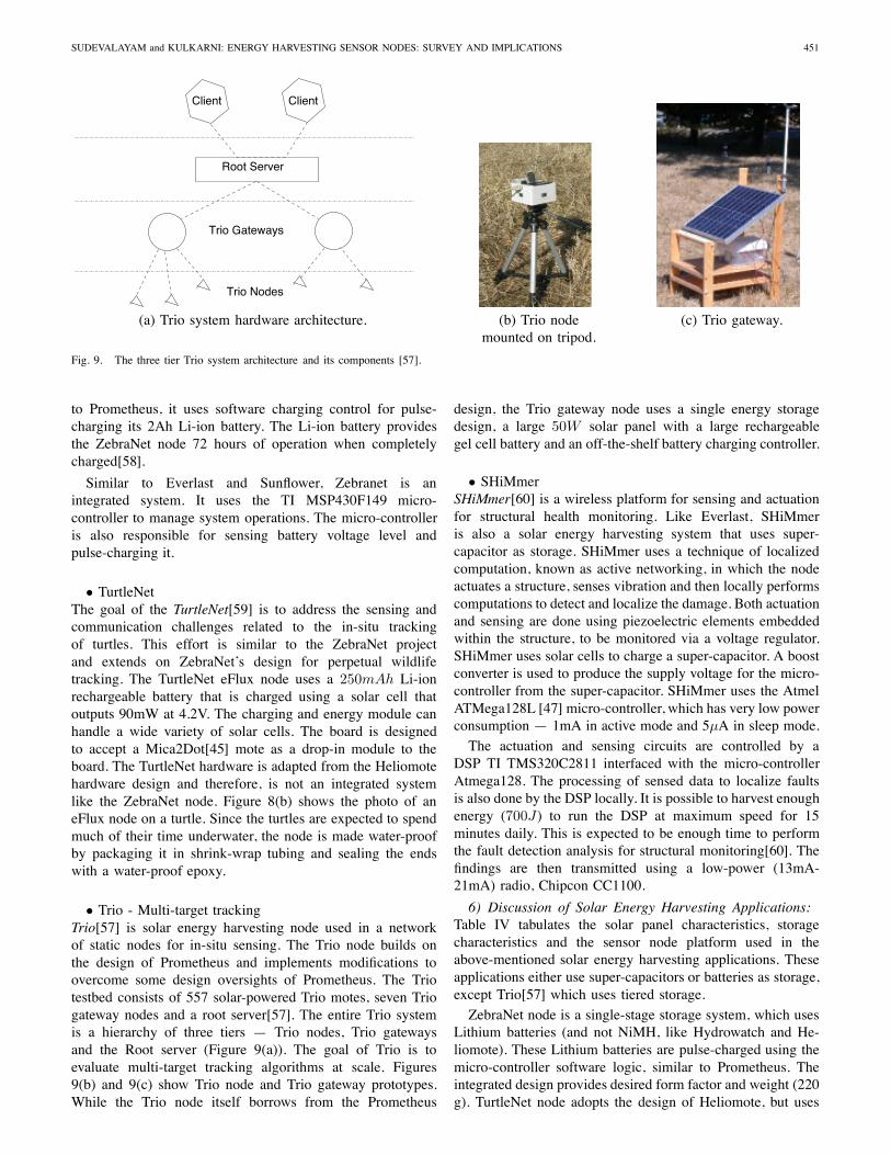
Fig. 9. The three tier Trio system architecture and its components [57].
to Prometheus, it uses software charging control for pulse-charging its 2Ah Li-ion battery. The Li-ion battery providesthe ZebraNet node 72 hours of operation when completelycharged[58].
Similar to Everlast and Sunflower, Zebranet is anintegrated system. It uses the TI MSP430F149 micro-controller to manage system operations. The micro-controlleris also responsible for sensing battery voltage level andpulse-charging it.
• TurtleNetThe goal of the TurtleNet[59] is to address the sensing andcommunication challenges related to the in-situ trackingof turtles. This effort is similar to the ZebraNet projectand extends on ZebraNet’s design for perpetual wildlifetracking. The TurtleNet eFlux node uses a 250mAh Li-ionrechargeable battery that is charged using a solar cell thatoutputs 90mW at 4.2V. The charging and energy module canhandle a wide variety of solar cells. The board is designedto accept a Mica2Dot[45] mote as a drop-in module to theboard. The TurtleNet hardware is adapted from the Heliomotehardware design and therefore, is not an integrated systemlike the ZebraNet node. Figure 8(b) shows the photo of aneFlux node on a turtle. Since the turtles are expected to spendmuch of their time underwater, the node is made water-proofby packaging it in shrink-wrap tubing and sealing the endswith a water-proof epoxy.
• Trio - Multi-target trackingTrio[57] is solar energy harvesting node used in a networkof static nodes for in-situ sensing. The Trio node builds onthe design of Prometheus and implements modifications toovercome some design oversights of Prometheus. The Triotestbed consists of 557 solar-powered Trio motes, seven Triogateway nodes and a root server[57]. The entire Trio systemis a hierarchy of three tiers — Trio nodes, Trio gatewaysand the Root server (Figure 9(a)). The goal of Trio is toevaluate multi-target tracking algorithms at scale. Figures9(b) and 9(c) show Trio node and Trio gateway prototypes.While the Trio node itself borrows from the Prometheus
design, the Trio gateway node uses a single energy storagedesign, a large 50W solar panel with a large rechargeablegel cell battery and an off-the-shelf battery charging controller.
• SHiMmerSHiMmer[60] is a wireless platform for sensing and actuationfor structural health monitoring. Like Everlast, SHiMmeris also a solar energy harvesting system that uses super-capacitor as storage. SHiMmer uses a technique of localizedcomputation, known as active networking, in which the nodeactuates a structure, senses vibration and then locally performscomputations to detect and localize the damage. Both actuationand sensing are done using piezoelectric elements embeddedwithin the structure, to be monitored via a voltage regulator.SHiMmer uses solar cells to charge a super-capacitor. A boostconverter is used to produce the supply voltage for the micro-controller from the super-capacitor. SHiMmer uses the AtmelATMega128L [47] micro-controller, which has very low powerconsumption — 1mA in active mode and 5μA in sleep mode.
The actuation and sensing circuits are controlled by aDSP TI TMS320C2811 interfaced with the micro-controllerAtmega128. The processing of sensed data to localize faultsis also done by the DSP locally. It is possible to harvest enoughenergy (700J) to run the DSP at maximum speed for 15minutes daily. This is expected to be enough time to performthe fault detection analysis for structural monitoring[60]. Thefindings are then transmitted using a low-power (13mA-21mA) radio, Chipcon CC1100.
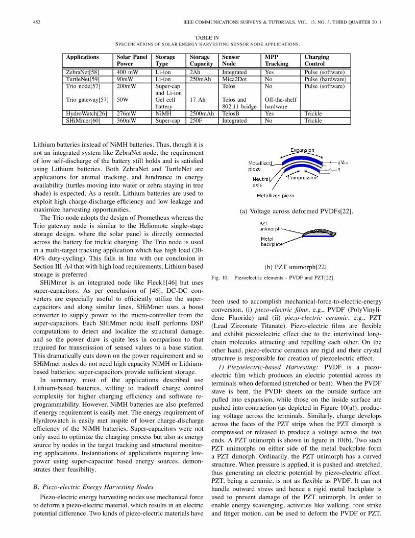
6) Discussion of Solar Energy Harvesting Applications:Table IV tabulates the solar panel characteristics, storagecharacteristics and the sensor node platform used in theabove-mentioned solar energy harvesting applications. Theseapplications either use super-capacitors or batteries as storage,except Trio[57] which uses tiered storage.
ZebraNet node is a single-stage storage system, which usesLithium batteries (and not NiMH, like Hydrowatch and He-liomote). These Lithium batteries are pulse-charged using themicro-controller software logic, similar to Prometheus. Theintegrated design provides desired form factor and weight (220g). TurtleNet node adopts the design of Heliomote, but uses
452 IEEE COMMUNICATIONS SURVEYS & TUTORIALS, VOL. 13, NO. 3, THIRD QUARTER 2011
TABLE IVSPECIFICATIONS OF SOLAR ENERGY HARVESTING SENSOR NODE APPLICATIONS.
Applications Solar Panel Storage Storage Sensor MPP ChargingPower Type Capacity Node Tracking Control
ZebraNet[58] 400 mW Li-ion 2Ah Integrated Yes Pulse (software)TurtleNet[59] 90mW Li-ion 250mAh Mica2Dot No Pulse (hardware)Trio node[57] 200mW Super-cap Telos No Pulse (software)
and Li-ionTrio gateway[57] 50W Gel cell 17 Ah Telos and Off-the-shelf
battery 802.11 bridge hardwareHydroWatch[26] 276mW NiMH 2500mAh TelosB Yes TrickleSHiMmer[60] 360mW Super-cap 250F Integrated No Trickle
Lithium batteries instead of NiMH batteries. Thus, though it isnot an integrated system like ZebraNet node, the requirementof low self-discharge of the battery still holds and is satisfiedusing Lithium batteries. Both ZebraNet and TurtleNet areapplications for animal tracking, and hindrance in energyavailability (turtles moving into water or zebra staying in treeshade) is expected. As a result, Lithium batteries are used toexploit high charge-discharge efficiency and low leakage andmaximize harvesting opportunities.The Trio node adopts the design of Prometheus whereas the
Trio gateway node is similar to the Heliomote single-stagestorage design, where the solar panel is directly connectedacross the battery for trickle charging. The Trio node is usedin a multi-target tracking application which has high load (20-40% duty-cycling). This falls in line with our conclusion inSection III-A4 that with high load requirements, Lithium basedstorage is preferred.SHiMmer is an integrated node like Fleck1[46] but uses
super-capacitors. As per conclusion of [46], DC-DC con-verters are especially useful to efficiently utilize the super-capacitors and along similar lines, SHiMmer uses a boostconverter to supply power to the micro-controller from thesuper-capacitors. Each SHiMmer node itself performs DSPcomputations to detect and localize the structural damage,and so the power draw is quite less in comparison to thatrequired for transmission of sensed values to a base station.This dramatically cuts down on the power requirement and soSHiMmer nodes do not need high capacity NiMH or Lithium-based batteries; super-capacitors provide sufficient storage.In summary, most of the applications described use
Lithium-based batteries, willing to tradeoff charge controlcomplexity for higher charging efficiency and software re-programmability. However, NiMH batteries are also preferredif energy requirement is easily met. The energy requirement ofHyrdrowatch is easily met inspite of lower charge-dischargeefficiency of the NiMH batteries. Super-capacitors were notonly used to optimize the charging process but also as energysource by nodes in the target tracking and structural monitor-ing applications. Instantiations of applications requiring low-power using super-capacitor based energy sources, demon-strates their feasibility.
B. Piezo-electric Energy Harvesting Nodes
Piezo-electric energy harvesting nodes use mechanical forceto deform a piezo-electric material, which results in an electricpotential difference. Two kinds of piezo-electric materials have
(a) Voltage across deformed PVDFs[22].
(b) PZT unimorph[22].
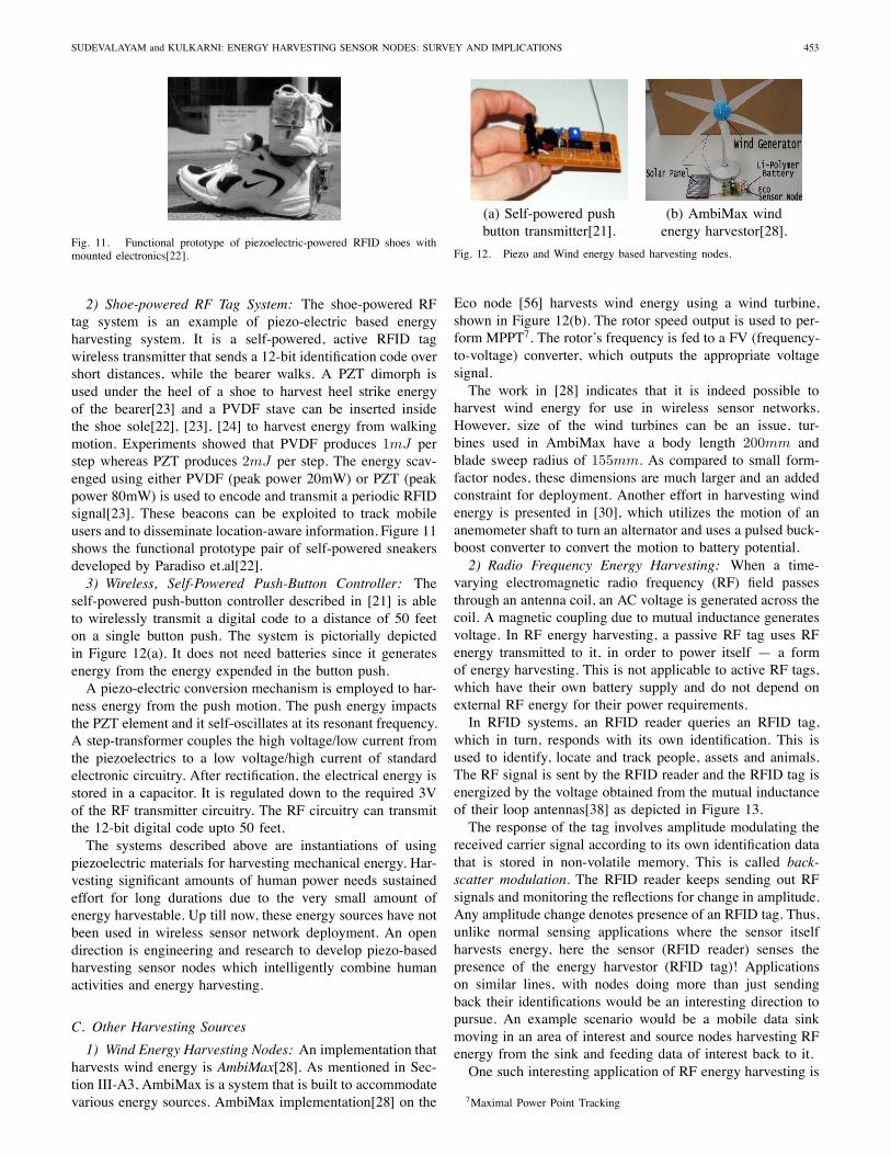
Fig. 10. Piezoelectric elements - PVDF and PZT[22].
been used to accomplish mechanical-force-to-electric-energyconversion, (i) piezo-electric films, e.g., PVDF (PolyVinyli-dene Fluoride) and (ii) piezo-electric ceramic, e.g., PZT(Lead Zirconate Titanate). Piezo-electric films are flexibleand exhibit piezoelectric effect due to the intertwined long-chain molecules attracting and repelling each other. On theother hand, piezo-electric ceramics are rigid and their crystalstructure is responsible for creation of piezoelectric effect.1) Piezoelectric-based Harvesting: PVDF is a piezo-
electric film which produces an electric potential across itsterminals when deformed (stretched or bent). When the PVDFstave is bent, the PVDF sheets on the outside surface arepulled into expansion, while those on the inside surface arepushed into contraction (as depicted in Figure 10(a)), produc-ing voltage across the terminals. Similarly, charge developsacross the faces of the PZT strips when the PZT dimorph iscompressed or released to produce a voltage across the twoends. A PZT unimorph is shown in figure in 10(b). Two suchPZT unimorphs on either side of the metal backplate forma PZT dimorph. Ordinarily, the PZT unimorph has a curvedstructure. When pressure is applied, it is pushed and stretched,thus generating an electric potential by piezo-electric effect.PZT, being a ceramic, is not as flexible as PVDF. It can nothandle outward stress and hence a rigid metal backplate isused to prevent damage of the PZT unimorph. In order toenable energy scavenging, activities like walking, foot strikeand finger motion, can be used to deform the PVDF or PZT.
SUDEVALAYAM and KULKARNI: ENERGY HARVESTING SENSOR NODES: SURVEY AND IMPLICATIONS 453
Fig. 11. Functional prototype of piezoelectric-powered RFID shoes withmounted electronics[22].
2) Shoe-powered RF Tag System: The shoe-powered RFtag system is an example of piezo-electric based energyharvesting system. It is a self-powered, active RFID tagwireless transmitter that sends a 12-bit identification code overshort distances, while the bearer walks. A PZT dimorph isused under the heel of a shoe to harvest heel strike energyof the bearer[23] and a PVDF stave can be inserted insidethe shoe sole[22], [23], [24] to harvest energy from walkingmotion. Experiments showed that PVDF produces 1mJ perstep whereas PZT produces 2mJ per step. The energy scav-enged using either PVDF (peak power 20mW) or PZT (peakpower 80mW) is used to encode and transmit a periodic RFIDsignal[23]. These beacons can be exploited to track mobileusers and to disseminate location-aware information. Figure 11shows the functional prototype pair of self-powered sneakersdeveloped by Paradiso et.al[22].3) Wireless, Self-Powered Push-Button Controller: The
self-powered push-button controller described in [21] is ableto wirelessly transmit a digital code to a distance of 50 feeton a single button push. The system is pictorially depictedin Figure 12(a). It does not need batteries since it generatesenergy from the energy expended in the button push.A piezo-electric conversion mechanism is employed to har-
ness energy from the push motion. The push energy impactsthe PZT element and it self-oscillates at its resonant frequency.A step-transformer couples the high voltage/low current fromthe piezoelectrics to a low voltage/high current of standardelectronic circuitry. After rectification, the electrical energy isstored in a capacitor. It is regulated down to the required 3Vof the RF transmitter circuitry. The RF circuitry can transmitthe 12-bit digital code upto 50 feet.The systems described above are instantiations of using
piezoelectric materials for harvesting mechanical energy. Har-vesting significant amounts of human power needs sustainedeffort for long durations due to the very small amount ofenergy harvestable. Up till now, these energy sources have notbeen used in wireless sensor network deployment. An opendirection is engineering and research to develop piezo-basedharvesting sensor nodes which intelligently combine humanactivities and energy harvesting.
C. Other Harvesting Sources
1) Wind Energy Harvesting Nodes: An implementation thatharvests wind energy is AmbiMax[28]. As mentioned in Sec-tion III-A3, AmbiMax is a system that is built to accommodatevarious energy sources. AmbiMax implementation[28] on the
(a) Self-powered push (b) AmbiMax windbutton transmitter[21]. energy harvestor[28].
Fig. 12. Piezo and Wind energy based harvesting nodes.
Eco node [56] harvests wind energy using a wind turbine,shown in Figure 12(b). The rotor speed output is used to per-form MPPT7. The rotor’s frequency is fed to a FV (frequency-to-voltage) converter, which outputs the appropriate voltagesignal.The work in [28] indicates that it is indeed possible to
harvest wind energy for use in wireless sensor networks.However, size of the wind turbines can be an issue, tur-bines used in AmbiMax have a body length 200mm andblade sweep radius of 155mm. As compared to small form-factor nodes, these dimensions are much larger and an addedconstraint for deployment. Another effort in harvesting windenergy is presented in [30], which utilizes the motion of ananemometer shaft to turn an alternator and uses a pulsed buck-boost converter to convert the motion to battery potential.2) Radio Frequency Energy Harvesting: When a time-
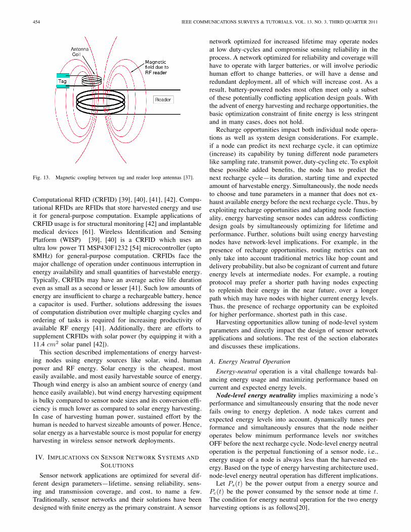
varying electromagnetic radio frequency (RF) field passesthrough an antenna coil, an AC voltage is generated across thecoil. A magnetic coupling due to mutual inductance generatesvoltage. In RF energy harvesting, a passive RF tag uses RFenergy transmitted to it, in order to power itself — a formof energy harvesting. This is not applicable to active RF tags,which have their own battery supply and do not depend onexternal RF energy for their power requirements.In RFID systems, an RFID reader queries an RFID tag,
which in turn, responds with its own identification. This isused to identify, locate and track people, assets and animals.The RF signal is sent by the RFID reader and the RFID tag isenergized by the voltage obtained from the mutual inductanceof their loop antennas[38] as depicted in Figure 13.The response of the tag involves amplitude modulating the
received carrier signal according to its own identification datathat is stored in non-volatile memory. This is called back-scatter modulation. The RFID reader keeps sending out RFsignals and monitoring the reflections for change in amplitude.Any amplitude change denotes presence of an RFID tag. Thus,unlike normal sensing applications where the sensor itselfharvests energy, here the sensor (RFID reader) senses thepresence of the energy harvestor (RFID tag)! Applicationson similar lines, with nodes doing more than just sendingback their identifications would be an interesting direction topursue. An example scenario would be a mobile data sinkmoving in an area of interest and source nodes harvesting RFenergy from the sink and feeding data of interest back to it.One such interesting application of RF energy harvesting is
7Maximal Power Point Tracking
454 IEEE COMMUNICATIONS SURVEYS & TUTORIALS, VOL. 13, NO. 3, THIRD QUARTER 2011
Fig. 13. Magnetic coupling between tag and reader loop antennas [37].
Computational RFID (CRFID) [39], [40], [41], [42]. Compu-tational RFIDs are RFIDs that store harvested energy and useit for general-purpose computation. Example applications ofCRFID usage is for structural monitoring [42] and implantablemedical devices [61]. Wireless Identification and SensingPlatform (WISP) [39], [40] is a CRFID which uses anultra low power TI MSP430F1232 [54] microcontroller (upto8MHz) for general-purpose computation. CRFIDs face themajor challenge of operation under continuous interruption inenergy availability and small quantities of harvestable energy.Typically, CRFIDs may have an average active life durationeven as small as a second or lesser [41]. Such low amounts ofenergy are insufficient to charge a rechargeable battery, hencea capacitor is used. Further, solutions addressing the issuesof computation distribution over multiple charging cycles andordering of tasks is required for increasing productivity ofavailable RF energy [41]. Additionally, there are efforts tosupplement CRFIDs with solar power (by equipping it with a11.4 cm2 solar panel [42]).This section described implementations of energy harvest-
ing nodes using energy sources like solar, wind, humanpower and RF energy. Solar energy is the cheapest, mosteasily available, and most easily harvestable source of energy.Though wind energy is also an ambient source of energy (andhence easily available), but wind energy harvesting equipmentis bulky compared to sensor node sizes and its conversion effi-ciency is much lower as compared to solar energy harvesting.In case of harvesting human power, sustained effort by thehuman is needed to harvest sizeable amounts of power. Hence,solar energy as a harvestable source is most popular for energyharvesting in wireless sensor network deployments.
IV. IMPLICATIONS ON SENSOR NETWORK SYSTEMS ANDSOLUTIONS
Sensor network applications are optimized for several dif-ferent design parameters—lifetime, sensing reliability, sens-ing and transmission coverage, and cost, to name a few.Traditionally, sensor networks and their solutions have beendesigned with finite energy as the primary constraint. A sensor
network optimized for increased lifetime may operate nodesat low duty-cycles and compromise sensing reliability in theprocess. A network optimized for reliability and coverage willhave to operate with larger batteries, or will involve periodichuman effort to change batteries, or will have a dense andredundant deployment, all of which will increase cost. As aresult, battery-powered nodes most often meet only a subsetof these potentially conflicting application design goals. Withthe advent of energy harvesting and recharge opportunities, thebasic optimization constraint of finite energy is less stringentand in many cases, does not hold.Recharge opportunities impact both individual node opera-
tions as well as system design considerations. For example,if a node can predict its next recharge cycle, it can optimize(increase) its capability by tuning different node parameterslike sampling rate, transmit power, duty-cycling etc. To exploitthese possible added benefits, the node has to predict thenext recharge cycle—its duration, starting time and expectedamount of harvestable energy. Simultaneously, the node needsto choose and tune parameters in a manner that does not ex-haust available energy before the next recharge cycle. Thus, byexploiting recharge opportunities and adapting node function-ality, energy harvesting sensor nodes can address conflictingdesign goals by simultaneously optimizing for lifetime andperformance. Further, solutions built using energy harvestingnodes have network-level implications. For example, in thepresence of recharge opportunities, routing metrics can notonly take into account traditional metrics like hop count anddelivery probability, but also be cognizant of current and futureenergy levels at intermediate nodes. For example, a routingprotocol may prefer a shorter path having nodes expectingto replenish their energy in the near future, over a longerpath which may have nodes with higher current energy levels.Thus, the presence of recharge opportunity can be exploitedfor higher performance, shortest path in this case.Harvesting opportunities allow tuning of node-level system
parameters and directly impact the design of sensor networkapplications and solutions. The rest of the section elaboratesand discusses these implications.
A. Energy Neutral Operation
Energy-neutral operation is a vital challenge towards bal-ancing energy usage and maximizing performance based oncurrent and expected energy levels.Node-level energy neutrality implies maximizing a node’s
performance and simultaneously ensuring that the node neverfails owing to energy depletion. A node takes current andexpected energy levels into account, dynamically tunes per-formance and simultaneously ensures that the node neitheroperates below minimum performance levels nor switchesOFF before the next recharge cycle. Node-level energy neutraloperation is the perpetual functioning of a sensor node, i.e.,energy usage of a node is always less than the harvested en-ergy. Based on the type of energy harvesting architecture used,node-level energy neutral operation has different implications.Let Ps(t) be the power output from a energy source and
Pc(t) be the power consumed by the sensor node at time t.The condition for energy neutral operation for the two energyharvesting options is as follows[20],
SUDEVALAYAM and KULKARNI: ENERGY HARVESTING SENSOR NODES: SURVEY AND IMPLICATIONS 455
(a) Harvest-Use (b) Harvest-Store-Use
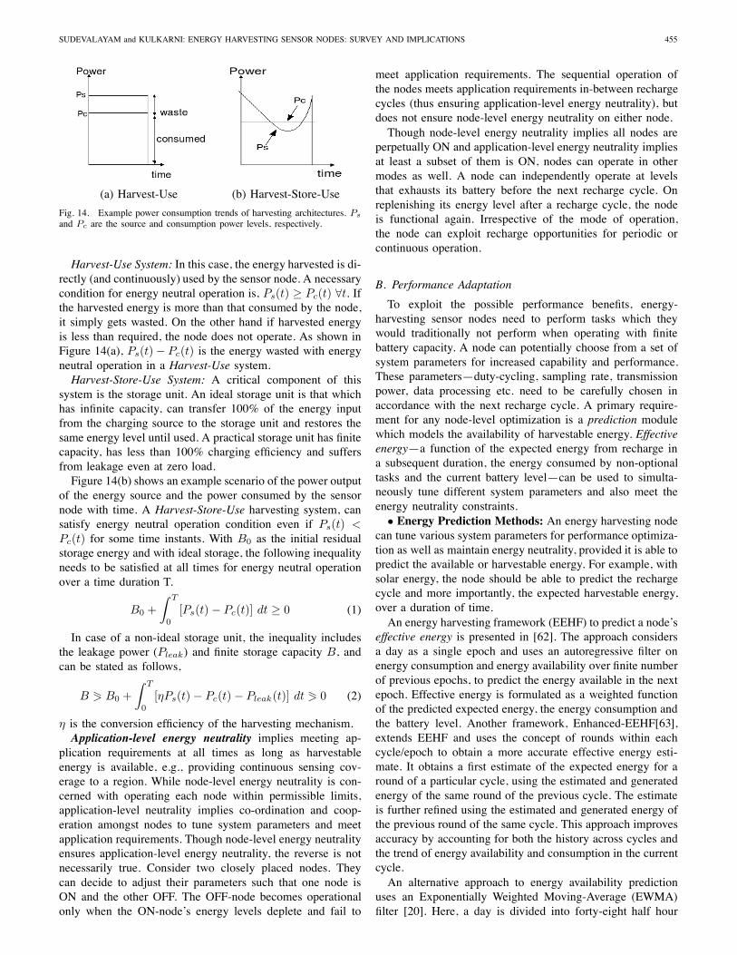
Fig. 14. Example power consumption trends of harvesting architectures. Ps
and Pc are the source and consumption power levels, respectively.
Harvest-Use System: In this case, the energy harvested is di-rectly (and continuously) used by the sensor node. A necessarycondition for energy neutral operation is, Ps(t) ≥ Pc(t) ∀t. Ifthe harvested energy is more than that consumed by the node,it simply gets wasted. On the other hand if harvested energyis less than required, the node does not operate. As shown inFigure 14(a), Ps(t) − Pc(t) is the energy wasted with energyneutral operation in a Harvest-Use system.Harvest-Store-Use System: A critical component of this
system is the storage unit. An ideal storage unit is that whichhas infinite capacity, can transfer 100% of the energy inputfrom the charging source to the storage unit and restores thesame energy level until used. A practical storage unit has finitecapacity, has less than 100% charging efficiency and suffersfrom leakage even at zero load.Figure 14(b) shows an example scenario of the power output
of the energy source and the power consumed by the sensornode with time. A Harvest-Store-Use harvesting system, cansatisfy energy neutral operation condition even if Ps(t) <Pc(t) for some time instants. With B0 as the initial residualstorage energy and with ideal storage, the following inequalityneeds to be satisfied at all times for energy neutral operationover a time duration T.
B0 +∫ T
0
[Ps(t) − Pc(t)] dt ≥ 0 (1)
In case of a non-ideal storage unit, the inequality includesthe leakage power (Pleak) and finite storage capacity B, andcan be stated as follows,
B � B0 +∫ T
0
[ηPs(t) − Pc(t) − Pleak(t)] dt � 0 (2)
η is the conversion efficiency of the harvesting mechanism.Application-level energy neutrality implies meeting ap-
plication requirements at all times as long as harvestableenergy is available, e.g., providing continuous sensing cov-erage to a region. While node-level energy neutrality is con-cerned with operating each node within permissible limits,application-level neutrality implies co-ordination and coop-eration amongst nodes to tune system parameters and meetapplication requirements. Though node-level energy neutralityensures application-level energy neutrality, the reverse is notnecessarily true. Consider two closely placed nodes. Theycan decide to adjust their parameters such that one node isON and the other OFF. The OFF-node becomes operationalonly when the ON-node’s energy levels deplete and fail to
meet application requirements. The sequential operation ofthe nodes meets application requirements in-between rechargecycles (thus ensuring application-level energy neutrality), butdoes not ensure node-level energy neutrality on either node.Though node-level energy neutrality implies all nodes are
perpetually ON and application-level energy neutrality impliesat least a subset of them is ON, nodes can operate in othermodes as well. A node can independently operate at levelsthat exhausts its battery before the next recharge cycle. Onreplenishing its energy level after a recharge cycle, the nodeis functional again. Irrespective of the mode of operation,the node can exploit recharge opportunities for periodic orcontinuous operation.
B. Performance Adaptation
To exploit the possible performance benefits, energy-harvesting sensor nodes need to perform tasks which theywould traditionally not perform when operating with finitebattery capacity. A node can potentially choose from a set ofsystem parameters for increased capability and performance.These parameters—duty-cycling, sampling rate, transmissionpower, data processing etc. need to be carefully chosen inaccordance with the next recharge cycle. A primary require-ment for any node-level optimization is a prediction modulewhich models the availability of harvestable energy. Effectiveenergy—a function of the expected energy from recharge ina subsequent duration, the energy consumed by non-optionaltasks and the current battery level—can be used to simulta-neously tune different system parameters and also meet theenergy neutrality constraints.• Energy Prediction Methods: An energy harvesting node
can tune various system parameters for performance optimiza-tion as well as maintain energy neutrality, provided it is able topredict the available or harvestable energy. For example, withsolar energy, the node should be able to predict the rechargecycle and more importantly, the expected harvestable energy,over a duration of time.An energy harvesting framework (EEHF) to predict a node’s
effective energy is presented in [62]. The approach considersa day as a single epoch and uses an autoregressive filter onenergy consumption and energy availability over finite numberof previous epochs, to predict the energy available in the nextepoch. Effective energy is formulated as a weighted functionof the predicted expected energy, the energy consumption andthe battery level. Another framework, Enhanced-EEHF[63],extends EEHF and uses the concept of rounds within eachcycle/epoch to obtain a more accurate effective energy esti-mate. It obtains a first estimate of the expected energy for around of a particular cycle, using the estimated and generatedenergy of the same round of the previous cycle. The estimateis further refined using the estimated and generated energy ofthe previous round of the same cycle. This approach improvesaccuracy by accounting for both the history across cycles andthe trend of energy availability and consumption in the currentcycle.An alternative approach to energy availability prediction
uses an Exponentially Weighted Moving-Average (EWMA)filter [20]. Here, a day is divided into forty-eight half hour
456 IEEE COMMUNICATIONS SURVEYS & TUTORIALS, VOL. 13, NO. 3, THIRD QUARTER 2011
slots, and energy available during each slot is estimated usinga weighted average of the energy availability in the same slotover previous days and energy estimate of the previous slot.Using appropriate weighting factors, the prediction can adaptto seasonal and diurnal variation in energy availability. Theaverage energy availability of a slot, x(i), is estimated usingthe following equation,
x(i) = αx(i − 1) + (1 − α)x(i) (3)
x(i), is the actual generated energy in slot i, x(i − 1), theaverage energy availability in slot i − 1 and α the weightingfactor. For a slot, its average energy availability over theprevious days, estimated using the above equation, is used asthe current prediction of the energy available in the slot. Foreach slot, the weight for older slots decreases exponentially.A weighting factor of 0.5 was empirically found to be anoptimal value for minimum prediction error [20]. Since, theenergy availability for a slot is updated at the end of everyslot, its adapts to energy availability variations across days.Further, the model could be optimized to tune the value of αas well based on seasonal patterns.• Node-level Adaptations: Each node can independently,
or in coordination with other nodes, use the effectiveenergy estimates to choose and tune parameter settings. Theparameters that need to be changed in order to positivelyinfluence performance metrics are largely a function of theapplication and solution requirements. Following is a list ofpotential system parameters that a node can tune based on itseffective energy estimate.
1. Duty-Cycling: Duty-cycling is the fraction of time anode is ON in a cycle of ON and OFF durations. The duty-cycling parameter of a node affects its performance and energyusage. A node with a higher duty-cycle uses energy at aquicker rate, but can provide benefits of higher samplingreliability and lower communication delay. Traditionally, vari-ations (if any) in the duty-cycle of a node are done to meetlifetime requirement based on the finite energy constraint.With energy-harvesting opportunities, the energy constraint isrelaxed and the duty-cycle parameter can be tuned more often(per epoch) and possibly maintained at higher levels. Basedon the predicted effective energy, nodes can adjust their duty-cycle parameters—higher duty-cycles for nodes with highereffective energy and lower duty-cycle for those with lowereffective energy.A mathematical model to predict the ideal battery size and
the rate of availability of harvestable energy is proposed in[20], [33]. The model is used to dynamically vary the nodeduty-cycle to maximize performance and also ensure node-level energy neutrality. The approach uses a non-decreasingfunction to model the relationship between node utility (per-formance) and duty-cycle. Thresholds of minimum and max-imum duty-cycling, correspond to minimum and maximumutility, respectively. Initially, optimal duty-cycles are computedfor each slot using the predicted values for energy availability.However, dynamic adjustment of this duty-cycle is necessarybecause the actual available energy in a slot may not be thesame as the predicted value. The solution uses the differencebetween predicted and available energy levels to increase or
decrease the duty-cycle parameter dynamically. If there isexcess energy available, then the duty-cycle is proportionallyincreased for the next slots whereas if there is deficit in energyavailability, then the duty-cycle is reduced in subsequent slotsto compensate for it.Reduction in duty-cycle variance in the presence of highly
variable energy availability is done in [64]. Unlike [33], aprioriknowledge of the energy profile is not assumed and duty-cycleis determined based only on current battery level. Similar to[33], the goal is to achieve Energy Neutral Operation (ENO)and Maximum performance, the dual condition referred toas the ENO-Max condition. An objective function is definedwhich minimizes the average square deviation of the batteryfrom its initial level. This implies that the battery energy is notin deficit as well as all the energy being harvested is beingused optimally. A Linear Quadratic (LQ) tracking problemis formulated using the above objective function as the costfunction so that the duty-cycle computed maintains the specificbattery level. Further, stability of duty-cycle is achieved byusing an exponentially weighted moving average of previousoutputs of the LQ tracker.The approach in [33] uses a utilization metric derived
from the application to compute the minimum and maximumdesired duty-cycles and duty-cycle is varied dynamically suchthat it is held within these thresholds. On the other hand,[64] does not need such inputs from the application level andinstead uses adaptive control theory to reduce the variabilityin duty-cycle, and at the same time, holding it as high aspossible while ensuring energy neutrality.
2. Transmit Power: One of the highest power consumingcomponents of a sensor node is the wireless radio. Settingradio transmit power to a moderate or low level is one of themechanisms to reduce the energy used for communication.Based on application requirements and availability of externalhardware like an antenna, traditional battery powered nodeshave a fixed setting for transmit power or one which does notchange too often[65]. A survey of power-control techniquesin wireless sensor networks, is presented in [66]. The mainobjective of these techniques is efficient energy usage. Theenergy conservation mechanisms are categorized as Activeand Passive. Passive energy conservation entails switchingoff the radio interface (parallel to the duty-cycling conceptdiscussed above) whereas Active energy conservation consistsof adjusting the radio transmit power using adaptive protocolsto conserve energy. While tuning of transmit power in batterypowered devices is aimed at optimizing energy usage, transmitpower adaptation in energy harvesting nodes can also be usedto increase communication range of the node and increaseefficiency of data dissemination protocols.Similar to duty-cycle variations, a node can adjust transmit
power based on the predicted effective energy [67]. In [67],each node uses localized information about its neighbourhoodto make routing decisions based on metrics like low latencyor low energy consumption. The topological extent of thislocalized information is defined as the node’s knowledgerange. The knowledge range of each node is computed basedon its current energy, expected energy and energy consumptionin the next period. Smaller the desired knowledge range,
SUDEVALAYAM and KULKARNI: ENERGY HARVESTING SENSOR NODES: SURVEY AND IMPLICATIONS 457
lower the transmit power and vice versa. Each node choosesthe next hop node within its knowledge range. Since highertransmission power implies larger communication ranges,a node with higher transmit power will have larger set ofneighbors and a larger set of available communication linksfor data-forwarding[67]. Transmit power values are mappedto corresponding expected energy usage, and energy neutraloperation is ensured (assuming no node-level sleep periods)based on the predicted effective energy.
3. Sensing Reliability: Sensing reliability is the quality ofinformation provided by the sensor. Similar to a node’s duty-cycle and transmit power, sensing reliability has a tradeoffwith energy usage. One of the deciding parameters of sensingreliability is the node’s sensing frequency—greater the fre-quency, greater is the sensing reliability. With battery-operatednodes, sensing frequency is seldom changed. However, withenergy harvesting nodes, sensing reliability can be variedproportionally with the predicted effective energy—greaterthe effective energy, greater is the reliability and vice versa.The actual mapping of sensing frequency and effective energydepends on the energy cost associated with sensing. A linearprogramming formulation is presented in [68] to maximize thesensing rate under the constraint that the energy in storagebe non-negative within the prediction interval. The approachsplits a day into a finite number of prediction intervals, and thesensing rate of each such interval is maximized depending onthe initial storage energy, the predicted energy and sensingrates of the previous prediction intervals of the same day.An online controller computes optimal sensing rates for allprediction intervals of a day at a time. It compensates forthe unstable power supply and holds the sensing rate almostconstant.Sensing reliability of applications like detection using
vision sensing, also depends on the amount of processing atthe sensor node. A vision sensor node can perform limitedprocessing on captured images to flag the detection of anobject based on simple background subtraction algorithms, orprocesses the image further to classify the detected objectsor approximate their location [16]. Each of the processingoptions has different energy costs and different sensingreliabilities. In such cases, the amount of processing at asensor node can be varied proportionally with the predictedeffective energy and higher sensing reliability can be obtainedwhenever possible.
4. Transmission Scheduling: As discussed earlier, wirelesstransmission uses relatively higher energy than other tasks.One technique to reduce the number of transmissions is toaggregate data from various nodes at intermediate nodes andtransmit fewer messages. Similarly, data at a single nodecan be aggregated in a temporal manner to send collectiveinformation and reduce the number of transmissions. Thesetechniques can be optimized further to account for energyharvesting nodes. Energy harvesting nodes can be responsiblefor data aggregation and transmission. Further, these nodescan schedule data dissemination based on predicted effectiveenergy. With solar-powered nodes, effective energy is closelyrelated to time-of-day. A possible approach is to have harvest-
ing nodes schedule immediate transmission of all aggregateddata during the day. Whereas, during night, the harvestingnodes primarily only sense, collect data from neighbors foraggregation, store the data and perform other critical tasks, ifany. Transmission of stored aggregate data can be scheduledfor later, when recharge opportunities are available. As aresult, transmission scheduling—toggling between low-powerand high-power states—can be vital for continuous sensingand data collection. An important requirement is to accuratelyestimate the patterns of energy availability, to switch betweenthe high and low power states.• Network-level Design: So far in this section, we have
seen how functionality of individual nodes can be tunedto exploit the presence of a harvestable energy source andimprove performance parameters. Presence of such energyharvesting nodes as part of the network, has an impact onnetwork-wide solutions and protocols. For example, varyingthe duty-cycle of a node will result in varying latenciesduring data dissemination. Similarly, varying the transmitpower will change the available routes through the node andits neighbourhood set. Following are examples of changesto traditional solutions which aim to exploit the presence ofenergy harvesting nodes,1. Routing: Routing protocols like Directed Diffusion [10],
depend on gradients from the data source to sink for routesetup. Usually, the best route is the one that delivers the firstresponse from the source to a data request query from thesink. Other route selection metrics include delivery probabil-ity and number of hops. Traditional sensor network routingprotocols also incorporate energy-based metrics to accountfor residual energy levels at nodes for routing decisions [69],[70], [71]. A taxonomy of energy efficient multicast routingprotocols [72] classifies them as, “active energy saving”,“passive energy saving”, “topology control” and “maximizingnetwork lifetime”. Active energy saving protocols try to find arouting path with minimum cumulative energy usage. On theother hand, maximizing network lifetime protocols focus onequitable energy usage across all nodes. A single node failureimplies network failure in this scenario. Passive energy savingprotocols involve turning off as many radios as possible whilemaintaining connectivity, whereas topology control protocolsinvolve tuning transmit power levels to maintain desiredconnectivity and simultaneously minimizing energy usage.Energy harvesting adds another dimension to route selec-
tion, that of effective-energy-aware route selection. Consider anetwork consisting of battery-powered and energy harvestingsensor nodes. An end-to-end residual energy routing metriccan select energy harvesting nodes as intermediaries for routes.Battery-powered nodes will then be used only as last hopnodes or as intermediaries only when no energy harvestingneighbor is in the vicinity[73]. Further, since the duty-cycleof each node on a route affects the end-to-end latency, it isbeneficial to have more energy harvesting nodes on the chosenroute[74]. These energy harvesting nodes tune their duty-cycleto higher values when the effective energy is higher. Thus,the routing metric of effective energy at each node, along withother metrics of link quality, duty-cycle etc., has the potentialto decrease routing responsibility and increase the lifetimeof battery-powered nodes. Maximizing the number of energy
458 IEEE COMMUNICATIONS SURVEYS & TUTORIALS, VOL. 13, NO. 3, THIRD QUARTER 2011
harvestable nodes on routing paths has the potential to increasethe overall lifetime of the network8.In order to choose routing paths according to energy dis-
tribution, [75] uses the EEHF model to predict the effectiveenergy at each node and proposes a routing metric basedon this energy value. A directed graph of the network iscreated with the inverse of a node’s effective energy as thecommunication cost for all edges into that node. A routingpath that minimizes the end-to-end cost for a given source-destination pair, exploits availability of effective energy.In the earlier discussion on duty-cycling, we cited [74]
which dynamically computes duty-cycle based on energyharvested, energy consumed and initial battery level. Dynamicchanges in duty-cycle will affect communication latency fromsource to destination The total latency along the path is asummation of delays at each node along the path. As a result,higher the duty-cycle of the node, lower the path latencyand vice versa. The approach in [76] builds on this duty-cycle computation and proposes three low-latency routing al-gorithms for duty-cycling nodes. Each node compares the first-hop latencies or second-hop latencies or full-path expectedlatencies, respectively, to choose the next-hop neighbour forrouting. Comparing the first-hop latency only, is short-sightedsince the second hop maybe contributing a higher value tothe path’s total latency. Accounting for second-hop latenciesbefore choosing the next-hop node for routing, is a morelatency-cognizant decision. Using full-path expected latenciesfor routing will result in the optimal path at the cost of in-creased number of updatemessages. If a routing algorithm hasto be “far-sighted”, every node has to exchange informationabout its state periodically, or on demand, thus adding torouting overhead.Some alternative routing algorithms for duty-cycling nodes,
based on harvesting-aware duty-cycle computation [74], arepresented in [67] and [77]. In [67], different routing protocolsare used for data of different priorities—the shortest orthe least latency path for delay-sensitive data, the mostenergy-efficient path for non-delay-sensitive but criticaldata and multiple paths for sensitive and critical data. Theapproach in [77] builds on work done in [67] and [76],and proposes a low-latency geographic routing algorithmfor asynchronous energy harvesting nodes that performduty-cycling. Low-latency is achieved by locally computingthe expected latency to sink, using geographic location ofneighbours and latency values to their potential neighbours.
2. Clustering: Another useful mechanism to route packetsin sensor networks is through formation of clusters. Nodesroute packets to cluster heads, which in turn, transmit packetson a cluster-head overlay to reach the destination [9], [78].Cluster formation and cluster head selection are importantissues to address in this category of solutions. Harvesting-capable nodes, with regular recharge opportunities, are suitablecandidates to be chosen as cluster heads[79]. Battery-powerednodes act as cluster members as often as possible, route pack-ets to harvesting-capable cluster heads and minimize power
8Overall lifetime of a network is defined as the time before the first nodein the network reaches end-of-life.
consumption. sLEACH[79], an extension to LEACH [9], is aharvesting-aware clustering technique for routing data. Usinga notion of rounds, sLEACH probabilistically chooses clus-ter heads for each round to spread the routing load. Theprobability of harvest-capable nodes is set to higher valuesthan battery-powered nodes. To do this, a constant weightingfactor is assigned to solar-powered nodes and its reciprocal isassigned to battery-powered nodes. As a result, if harvestingnodes exist in a cluster, one of them will be chosen as acluster head with high probability. A cluster-head that hassubsequently switched to battery operation, can toggle itsweighting factor and handover its responsibility to anothersolar-powered node. As compared to LEACH, which assignsuniform probabilities to all nodes for cluster head selection,sLEACH is demonstrated to increase the overall lifetime by10%-45% in a network ranging from 5 to 25 energy-harvestingnodes[79].Experimental evaluation of sLEACH is based on simulation
and simple correlations of harvesting availability and recharge.Interesting extensions to sLEACH would be to evaluate itbased on a prototype deployment and from energy availabilitytraces to understand its improvement in realistic environments.Further, sLEACH assigns a fixed weighting factor to allharvesting-capable nodes (assuming homogeneous harvestingavailability and capability). Correlating the weighting factorto the effective energy, the harvesting periodicity and theresidual energy at each node would make the approach moregeneric. One such extension is presented in [63], whereineach node assigns itself a cost depending on its predicted andresidual energy and its minimum required consumption energy.Higher the surplus energy, lower the cost. Each such potentialcluster-head waits for a time proportional to its cost beforesending out an advertisement. Any node that receives such anadvertisement will be a member of that cluster. Ties in cluster-head selection are resolved by choosing the one which requiresless transmission energy. Isolated nodes become membersor sub-members of nearby clusters or form single-memberclusters of their own. This approach has been shown[63] toguarantee better clustering than probabilistic clustering.Clustering is a useful technique to mask network connec-
tivity and topology changes. Applications, like data collectionand data routing, can co-ordinate with cluster-heads for theiroperations. Cluster-heads in-turn can co-ordinate with thedynamic set of nodes. Clustering techniques that provide thisbenefit in mobile environments are presented in [80], [81].These techniques can be extended to adapt to not only mobilitybut also to topology changes caused by adaptive control ofother harvesting-based node-level parameters like transmitpower, duty-cycling etc.3. Data Collection: Several sensor network applications
require periodic collection of data, with higher rates translatingto better quality. Battery-powered nodes, with finite energycapacity, use low data rates in favour of extended lifetime.A method for energy-efficient data collection is using data-aggregation techniques. While data-aggregation techniqueshave been proposed [82] to efficiently gather data on the axesof energy, accuracy, reliability, latency etc., harvesting makesthe choice of in-network aggregation decisions more dynamic.Further, short-term and long-term aggregation locations and
SUDEVALAYAM and KULKARNI: ENERGY HARVESTING SENSOR NODES: SURVEY AND IMPLICATIONS 459
policies can be formulated based on harvesting potential ateach node and the expected workload.An approach for high throughput data extraction from all
nodes in the network while meeting per-node energy neutralityconstraints, is presented in [83]. An optimal lexicographicalrate is estimated with the aim of maximizing the minimumdata rate across all nodes. With a lexicographical rate assign-ment, it is not possible to further increase the rate of one nodewithout decreasing the rate of another. The rate assignmentproblem is formulated as a linear optimization problem, andboth centralized and distributed solutions are proposed. Thecentralized approach accounts for effective energy at nodes(i.e., predicted and residual energy) and computes the datarates and routes from each source to a single sink. Thedistributed solution assumes prior knowledge of routes to thesink and solves the data rate assignment problem.Attempts to maximize data rate have also been made in
[84], [85]. A new metric is introduced, MESW (MaximumEnergetically Sustainable Workload), which refers to themaximum workload that can be sustained by the networkunder given energy constraints. Similar to [64], thatmaximized node duty cycle while ensuring energy neutraloperation, the MESW metric aims to maximize the data rate ateach node with energy neutrality. A network graph annotatedwith channel capacities is used to find the maximum flowbetween any two nodes by solving the Maxflow problem.However, this assumes that each node has infinite flowcapacity. The MESW approach [84], [85] adds the constraintof each node having limited flow capacity through it andthus formulates a node-constrained network flow problem.The maximum data rate is then computed by solving themaxflow problem on the node-constrained network flow graph.
4. Miscellaneous:Consider the problem of deploying a sensor network to
provide sensing coverage to a given region of interest. Tra-ditional techniques rely on redundant and dense placement ofnodes [18], [19], with nodes coordinating and operating insubsets to address coverage and lifetime requirements. Withenergy harvesting, if the harvestable energy of a node is suchthat it can operate for long periods, lesser redundancy in nodeplacement maybe sufficient to meet coverage requirements forlonger durations. The problem of interest would be to comeup with a placement technique that maximizes the numberof locations for placement of harvesting-aware nodes. As aresult, minimizing the number of battery-powered nodes hasthe potential to decrease the number of redundant near-locatednodes, resulting in cost reduction and also longer coverageguarantees.Another potential implication of harvesting is on MAC
layer protocols. Several sensor and wireless network MACprotocols [86] exist—CSMA-based and TDMA-based. CSMAand low-power listening based MAC protocol like BMAC [7]and XMAC [8] use sender-based preambles to intimate re-ceivers of incoming data. Receiver initiated versions, like RI-MAC [87], do not send preambles. Instead, a sender remainsawake till it hears a beacon from the intended receiver. Theabove protocols work with duty-cycled nodes and the length ofthe preamble or the time for which sender waits for a receiver
depends on the sleep period of the receiver. The duty-cycleparameters are fixed and seldom change when operated withbattery-powered nodes. In presence of harvesting, based on theeffective energy at a node, the preamble length or wait durationcan be increased or decreased to allow energy-scarce nodes tosleep for longer durations. The problem of relating expectedenergy levels of all nodes in the network, their routing pathsand traffic patterns, with duty-cycle and MAC parameters ofeach, is of potential interest. Further, with TDMA-based MACprotocols [6], [88], [89], nodes are either assigned a fixednumber of slots or allotted slots on request. Harvesting nodescan be assigned, or can request for, slots as a function oftheir expected energy. Nodes with higher levels of expectedenergy can use multiple slots in a round for communication.As a result, a potential direction to explore, is the automaticassignment of slots for nodes based on their expected energyand traffic patterns.In this section, we described various node-level and
network-level implications of energy harvesting on sensornetwork design. Potential node and network-level parametersto tune and affect network design and performance werepresented. As discussed above, system design and node-leveladaptations are inter-dependent. Tuning of node-level param-eters affects network solutions and communication protocols,e.g., change in transmit power changes neighborhood andaffects routing metrics, variations in duty-cycle affect MACparameters, change in node sensing rates affect network datacollection. This reasserts the point that design considerationsof sensor network applications and node-level power man-agement mechanisms are tightly coupled. The description ofnode-level and network-level implications presented examplesand potential directions of solutions to exploit harvestingopportunities in order to simultaneously improve performanceparameters and network lifetime.
V. CONCLUSIONS
The capability of a wireless sensor node to harvest energyhas the potential to simultaneously address the conflictingdesign goals of lifetime and performance. In this paper, wediscussed various aspects of energy harvesting systems. Wepresented basic concepts of harvesting systems—architectures,types of harvestable energy sources, and storage technologies.We described details of existing energy harvesting sensornodes and applications, most notably the ones dependent onsolar energy. Further, we presented insights into implicationsof recharge opportunities on node-level operations and designof sensor network applications and solutions. We believe theseinsights will motivate further research towards usage of energyharvesting sensor nodes and their applications.
REFERENCES
[1] A. Mainwaring, D. Culler, J. Polastre, R. Szewczyk, and J. Anderson,“Wireless Sensor Networks for Habitat Monitoring,” in Proc. 1st ACMInternational Workshop on Wireless Sensor Networks and Applications.ACM, 2002, pp. 88–97.
[2] G. Werner-Allen, K. Lorincz, M. Ruiz, O. Marcillo, J. Johnson, J. Lees,and M. Welsh, “Deploying a Wireless Sensor Network on an ActiveVolcano,” IEEE Internet Comput., vol. 10, no. 2, pp. 18–25, March-April 2006.

460 IEEE COMMUNICATIONS SURVEYS & TUTORIALS, VOL. 13, NO. 3, THIRD QUARTER 2011
[3] R.-G. Lee, K.-C. Chen, S.-S. Chiang, C.-C. Lai, H.-S. Liu, and M.-S. Wei, “A Backup Routing with Wireless Sensor Network for BridgeMonitoring System,” in Annual Conference on Communication Networksand Services Research. IEEE Computer Society, 2006, pp. 157–161.
[4] K. Chebrolu, B. Raman, N. Mishra, P. K. Valiveti, and R. Kumar,“Brimon: A Sensor Network System for Railway Bridge Monitoring,”in Proc. 6th International Conference on Mobile Systems, Applications,and Services. ACM, 2008, pp. 2–14.
[5] M. Karpiriski, A. Senart, and V. Cahill, “Sensor Networks for SmartRoads,” in Fourth Annual IEEE International Conference on PervasiveComputing and Communications Workshops, Mar. 2006, pp. 310–314.
[6] W. Ye, J. Heidemann, and D. Estrin, “An Energy-efficient MAC Protocolfor Wireless Sensor Networks,” in INFOCOM 2002. Proc. Twenty-FirstAnnual Joint Conference of the IEEE Computer and CommunicationsSocieties., vol. 3, 2002, pp. 1567–1576.
[7] J. Polastre, J. Hill, and D. Culler, “Versatile Low Power Media Accessfor Wireless Sensor Networks,” in Proc. 2nd International Conferenceon Embedded Networked Sensor Systems. ACM, 2004, pp. 95–107.
[8] M. Buettner, G. V. Yee, E. Anderson, and R. Han, “X-MAC: A ShortPreamble MAC Protocol for Duty-cycled Wireless Sensor Networks,”in Proc. 4th International Conference on Embedded Networked SensorSystems. ACM, 2006, pp. 307–320.
[9] W. Heinzelman, A. Chandrakasan, and H. Balakrishnan, “Energy-efficient Communication Protocol for Wireless MicroSensor Networks,”in Proc. 33rd Annual Hawaii International Conference on SystemSciences., Jan. 2000, p. 8020. vol.8.
[10] C. Intanagonwiwat, R. Govindan, and D. Estrin, “Directed Diffusion: AScalable and Robust Communication Paradigm for Sensor Networks,”in Proc. 6th Annual International Conference on Mobile Computing andNetworking. ACM, 2000, pp. 56–67.
[11] P. Desnoyers, D. Ganesan, H. Li, M. Li, and P. Shenoy, “PRESTO:A Predictive Storage Architecture for Sensor Networks,” in Proc. 10thConference on Hot Topics in Operating Systems. USENIX Association,2005, p. 23.
[12] S. Ganeriwal, D. Ganesan, H. Shim, V. Tsiatsis, and M. B. Srivastava,“Estimating Clock Uncertainty for Efficient Duty-cycling in SensorNetworks,” in Proc. Third ACM Conference on Sensor NetworkingSystems, Nov. 2005, pp. 130–141.
[13] P. Dutta, M. Grimmer, A. Arora, S. Bibyk, and D. Culler, “Designof a Wireless Sensor Network Platform for Detecting Rare, Random,and Ephemeral Events,” in In The 4 th International Conference onInformation Processing in Sensor Networks, 2005, pp. 497–502.
[14] H. Liu, A. Chandra, and J. Srivastava, “eSENSE: Energy EfficientStochastic Sensing Framework for Wireless Sensor Platforms,” in Proc.Fifth International Conference on Information Processing in SensorNetworks, April 2006, pp. 235–242.
[15] O. Gnawali, K.-Y. Jang, J. Paek, M. Vieira, R. Govindan, B. Greenstein,A. Joki, D. Estrin, and E. Kohler, “The Tenet Architecture for TieredSensor Networks,” in Proc. 4th International Conference on EmbeddedNetworked Sensor Systems. ACM, 2006, pp. 153–166.
[16] P. Kulkarni, “Senseye: A Multi-tier Heterogeneous Camera SensorNetwork,” Ph.D. dissertation, University of Massachusetts, Amherst,2007, adviser-Prashant Shenoy and Adviser-Deepak Ganesan.
[17] P. Kulkarni, D. Ganesan, and P. Shenoy, “The Case for Multi-tier CameraSensor Networks,” in Proc. International Workshop on Network andoperating Systems support for digital audio and video. ACM, 2005,pp. 141–146.
[18] X. Wang, G. Xing, Y. Zhang, C. Lu, R. Pless, and C. Gill, “Integratedcoverage and connectivity configuration in wireless sensor networks,”in Proc. First International Conference on Embedded Networked SensorSystems. ACM, 2003, pp. 28–39.
[19] S. Kumar, T. H. Lai, and J. Balogh, “On k-coverage in a Mostly SleepingSensor Network,” Wireless Networks, vol. 14, no. 3, pp. 277–294, 2008.
[20] A. Kansal, J. Hsu, S. Zahedi, and M. B. Srivastava, “Power Managementin Energy Harvesting Sensor Networks,” Trans. Embedded ComputingSystems, vol. 6, no. 4, p. 32, 2007.
[21] J. A. Paradiso and M. Feldmeier, “A Compact, Wireless, Self-PoweredPushbutton Controller,” in Proc. 3rd International Conference on Ubiq-uitous Computing. Springer-Verlag, 2001, pp. 299–304.
[22] N. Shenck and J. Paradiso, “Energy Scavenging with Shoe-mountedPiezoelectrics,” IEEE Micro, vol. 21, no. 3, pp. 30–42, May/Jun 2001.
[23] J. Kymissis, C. Kendall, J. Paradiso, and N. Gershenfeld, “ParasiticPower Harvesting in Shoes,” in Second International Symposium onWearable Computers., Oct 1998, pp. 132–139.
[24] T. Starner, “Human-powered Wearable Computing,” IBM Systems Jour-nal., vol. 35, no. 3-4, pp. 618–629, 1996.
[25] X. Jiang, J. Polastre, and D. Culler, “Perpetual Environmentally Powered
Sensor Networks,” in Fourth International Symposium on InformationProcessing in Sensor Networks., April 2005, pp. 463–468.
[26] J. Taneja, J. Jeong, and D. Culler, “Design, Modeling, and CapacityPlanning for Micro-solar Power Sensor Networks,” in Proc. 7th Interna-tional Conference on Information Processing in Sensor Networks, 2008,pp. 407–418.
[27] V. Raghunathan, A. Kansal, J. Hsu, J. Friedman, and M. Srivastava, “De-sign Considerations for Solar Energy Harvesting Wireless EmbeddedSystems,” Fourth International Symposium on Information Processingin Sensor Networks, pp. 457–462, April 2005.
[28] C. Park and P. Chou, “AmbiMax: Autonomous Energy HarvestingPlatform for Multi-Supply Wireless Sensor Nodes,” 3rd Annual IEEECommunications Society on Sensor and Ad Hoc Communications andNetworks, vol. 1, pp. 168–177, Sept. 2006.
[29] H. Kulah and K. Najafi, “Energy Scavenging From Low-FrequencyVibrations by Using Frequency Up-Conversion for Wireless SensorApplications,” IEEE Sensors J., vol. 8, pp. 261–268, 2008.
[30] M. Weimer, T. Paing, and R. Zane, “Remote Area Wind EnergyHarvesting for Low-power Autonomous Sensors,” 37th IEEE PowerElectronics Specialists Conference, pp. 1–5, June 2006.
[31] S. Chalasani and J. Conrad, “A Survey of Energy Harvesting Sources forEmbedded Systems,” in IEEE Southeastcon, April 2008, pp. 442–447.
[32] S. Roundy, D. Steingart, L. Frechette3, P. Wright, and J. Rabaey, PowerSources for Wireless Sensor Networks. Springer Berlin, 2004, vol.Volume 2920, no. 978-3-540-20825-9.
[33] J. Hsu, S. Zahedi, A. Kansal, M. Srivastava, and V. Raghunathan,“Adaptive Duty Cycling for Energy Harvesting Systems,” in Proc. 2006International Symposium on Low Power Electronics and Design. ACM,2006, pp. 180–185.
[34] F. Simjee and P. H. Chou, “Everlast: Long-life, Supercapacitor-operatedWireless Sensor Node,” in Proc. 2006 International Symposium on LowPower Electronics and Design. ACM, 2006, pp. 197–202.
[35] P. Stanley-Marbell and D. Marculescu, “An 0.9 × 1.2′′, Low Power,Energy-harvesting System with Custom Multi-channel CommunicationInterface,” in Proc. Conference on Design, automation and test inEurope. EDA Consortium, 2007, pp. 15–20.
[36] J. Paradiso, “Systems for Human-powered Mobile Computing,” 43rdACM/IEEE Design Automation Conference, pp. 645–650, July 2006.
[37] “Tag Tuning,” http://www.atmel.com/.[38] R. Want, “An Introduction to RFID Technology,” IEEE Pervasive
Comput., vol. 5, no. 1, p. 25, 2006.[39] M. Buettner, B. Greenstein, A. Sample, J. R. Smith, and D. Wetherall,
“Revisiting Smart Dust with RFID Sensor Networks,” in Proc. 7th ACMWorkshop on Hot Topics in Networks (Hotnets-VII), Oct. 2008.
[40] A. P. Sample, D. J. Yeager, P. S. Powledge, A. V. Mamishev, and J. R.Smith, “Design of an RFID-Based Battery-Free Programmable SensingPlatform,” in IEEE Trans. Instrum. Meas., vol. 57, no. 11, 2008, pp.2608–2615.
[41] B. Ransford, S. Clark, M. Salajegheh, and K. Fu, “Getting ThingsDone on Computational RFIDs with Energy-Aware Checkpointing andVoltage-Aware Scheduling,” in Proc. USENIX Workshop on PowerAware Computing and Systems (HotPower), December 2008.
[42] S. S. Clark, J. Gummeson, K. Fu, and D. Ganesan, “TowardsAutonomously-Powered CRFIDs,” in Workshop on Power Aware Com-puting and Systems (HotPower 2009), Oct. 2009.
[43] J. Polastre, R. Szewczyk, and D. Culler, “Telos: Enabling Ultra-lowPower Wireless Research,” in Fourth International Symposium on In-formation Processing in Sensor Networks, April 2005, pp. 364–369.
[44] J. L. Hill and D. E. Culler, “Mica: A Wireless Platform for DeeplyEmbedded Networks,” IEEE Micro, vol. 22, no. 6, pp. 12–24, 2002.
[45] “Mica, Mica2, Mica2Dot, MicaZ, Telos,”http://www.xbow.com/products.
[46] P. Corke, P. Valencia, P. Sikka, T. Wark, and L. Overs, “Long-durationSolar-powered Wireless Sensor Networks,” in Proc. 4th Workshop onEmbedded Networked Sensors. ACM, 2007, pp. 33–37.
[47] “ATmega128,” http://www.atmel.com/.[48] “Nordic nRF903,” http://www.nordicsemi.com.[49] “Microchip PIC16F7X7,” http://www.microchip.com/.[50] “Nordic nRF2401,” http://www.nordicsemi.com.[51] M. Minami, T. Morito, H. Morikawa, and T. Aoyama., “Solar biscuit: A
Battery-less Wireless Sensor Network System for Environmental Moni-toring Applications.” in The 2nd International Workshop on NetworkedSensing Systems, 2005, 2007.
[52] “Microchip PIC18LF452,” http://www.microchip.com/.[53] “Chipcon CC1000 Radio,” http://www.ti.com/corp/docs/chipcon/index.htm.[54] “Texas Instruments MSP430F1232,” http://focus.ti.com/lit/ds/symlink/
msp430f1232.pdf.[55] “TinyOS,” http://www.tinyos.net/.

SUDEVALAYAM and KULKARNI: ENERGY HARVESTING SENSOR NODES: SURVEY AND IMPLICATIONS 461
[56] C. Park, J. Liu, and P. H. Chou, “Eco: an Ultra-Compact Low-PowerWireless Sensor Node for Real-Time Motion Monitoring,” in Proc.Information Processing in Sensor Networks. IEEE Press, April 2005,pp. 398–403.
[57] P. Dutta, J. Hui, J. Jeong, S. Kim, C. Sharp, J. Taneja, G. Tolle, K. White-house, and D. Culler, “Trio: Enabling Sustainable and Scalable OutdoorWireless Sensor Network Deployments,” in Proc. Fifth InternationalConference on Information Processing in Sensor Networks. ACM,2006, pp. 407–415.
[58] P. Zhang, C. M. Sadler, S. A. Lyon, and M. Martonosi, “HardwareDesign Experiences in ZebraNet,” in Proc. Second International Con-ference on Embedded Networked Sensor Systems. ACM, 2004, pp.227–238.
[59] “TurtleNet,” http://prisms.cs.umass.edu/dome/turtlenet.[60] D. Musiani, K. Lin, and T. S. Rosing, “Active Sensing Platform for
Wireless Structural Health Monitoring,” in Proc. Sixth InternationalConference on Information Processing in Sensor Networks. ACM,2007, pp. 390–399.
[61] D. Halperin, T. Heydt-Benjamin, B. Ransford, S. Clark, B. Defend,W. Morgan, K. Fu, T. Kohno, and W. Maisel, “Pacemakers andImplantable Cardiac Defibrillators: Software Radio Attacks and Zero-Power Defenses,” in IEEE Symposium on Security and Privacy, May2008, pp. 129–142.
[62] A. Kansal and M. B. Srivastava, “An Environmental Energy HarvestingFramework for Sensor Networks,” in Proc. 2003 International Sympo-sium on Low Power Electronics and Design. ACM, 2003, pp. 481–486.
[63] K. Kinoshita, T. Okazaki, H. Tode, and K. Murakami, “A Data GatheringScheme for Environmental Energy-Based Wireless Sensor Networks,” in5th IEEE Consumer Communications and Networking Conference., Jan.2008, pp. 719–723.
[64] C. Vigorito, D. Ganesan, and A. Barto, “Adaptive Control of DutyCycling in Energy-Harvesting Wireless Sensor Networks,” 4th AnnualIEEE Communications Society Conference on Sensor, Mesh and Ad HocCommunications and Networks., pp. 21–30, June 2007.
[65] S. Lin, J. Zhang, G. Zhou, L. Gu, J. A. Stankovic, and T. He, “AdaptiveTransmission Power Control for Wireless Sensor Networks,” in Proc.Fourth International Conference on Embedded Networked Sensor Sys-tems. ACM, 2006, pp. 223–236.
[66] N. Pantazis and D. Vergados, “A Survey on Power Control Issues inWireless Sensor Networks,” IEEE Commun. Surveys Tutorials, vol. 9,no. 4, pp. 86 –107, Oct. 2007.
[67] D. Noh, J. Kim, J. Lee, D. Lee, H. Kwon, and H. Shin, “Priority-based Routing for Solar-Powered Wireless Sensor Networks,” in 2ndInternational Symposium on Wireless Pervasive Computing., Feb. 2007.
[68] C. Moser, L. Thiele, D. Brunelli, and L. Benini, “Adaptive PowerManagement in Energy Harvesting Systems,” in Design, Automationand Test in Europe Conference and Exhibition., April 2007, pp. 1–6.
[69] R. Shah and J. Rabaey, “Energy Aware Routing for Low Energy AdHoc Sensor Networks,” in Proc. IEEE Wireless Communications andNetworking Conference, vol. 1, Mar 2002, pp. 350–355.
[70] Q. Li, J. Aslam, and D. Rus, “Online Power-aware Routing in WirelessAd-hoc Networks,” in Proc. 7th Annual International Conference onMobile Computing and Networking. ACM, 2001, pp. 97–107.
[71] Y. T. Hou, Y. Shi, J. Pan, and S. F. Midkiff, “MRPC: Maximizing theLifetime of Wireless Sensor Networks through Optimal Single-SessionFlow Routing,” IEEE Trans. Mobile Comput., vol. 5, no. 9, pp. 1255–1266, Sept. 2006.
[72] L. Junhai, Y. Danxia, X. Liu, and F. Mingyu, “A Survey of MulticastRouting Protocols for Mobile Ad-Hoc Networks,” IEEE Commun.Surveys Tutorials, vol. 11, no. 1, pp. 78–91, Jan. 2009.
[73] T. Voigt, H. Ritter, and J. Schiller, “Utilizing Solar Power in WirelessSensor Networks,” in Proc. Twenty Eighth Annual IEEE InternationalConference on Local Computer Networks., Oct 2003, pp. 416–422.
[74] A. Kansal, D. Potter, and M. B. Srivastava, “Performance Aware Taskingfor Environmentally Powered Sensor Networks,” SIGMETRICS Perform.Eval. Rev., vol. 32, no. 1, pp. 223–234, 2004.
[75] A. Kansal, J. Hsu, M. Srivastava, and V. Raghunathan, “HarvestingAware Power Management for Sensor Networks,” in Proc. 43rd AnnualConference on Design automation. ACM, 2006, pp. 651–656.
[76] H. Kwon, D. Noh, J. Kim, J. Lee, D. Lee, and H. Shin, Low-LatencyRouting for Energy-Harvesting Sensor Networks. Springer Berlin, 2007,vol. Volume 4611, no. 978-3-540-73548-9.
[77] D. Noh, I. Yoon, and H. Shin, “Low-Latency Geographic Routing forAsynchronous Energy-Harvesting WSNs,” JNW, vol. 3, no. 1, pp. 78–85, 2008.
[78] Deepak Ganesan and Ben Greenstein and Denis Perelyubskiy and Deb-orah Estrin and John Heidemann, “An Evaluation of Multi-resolution
Storage for Sensor Networks,” in Proc. 1st International Conference onEmbedded Networked Sensor Systems. ACM, 2003, pp. 89–102.
[79] T. Voigt, A. Dunkels, J. Alonso, H. Ritter, and J. Schiller, “Solar-aware clustering in wireless sensor networks,” in Ninth InternationalSymposium on Computers and Communications., vol. 1, June 2004, pp.238–243.
[80] J. Yu and P. Chong, “A Survey of Clustering Schemes for Mobile AdHoc Networks,” IEEE Commun. Surveys Tutorials, vol. 7, no. 1, pp.32–48, Jan. 2005.
[81] H. Cheng and J. Cao, “A Design Framework and Taxonomy for HybridRouting Protocols in Mobile Ad hoc Networks,” IEEE Commun. Surveysand Tutorials, vol. 10, no. 3, pp. 62–73, July 2008.
[82] R. Rajagopalan and P. Varshney, “Data-aggregation Techniques in Sen-sor Networks: A Survey,” IEEE Commun. Surveys Tutorials, vol. 8,no. 4, pp. 48–63, Oct. 2006.
[83] K.-W. Fan, Z. Zheng, and P. Sinha, “Steady and Fair Rate Allocationfor Rechargeable Sensors in Perpetual Sensor Networks,” in Proc. 6thACM Conference on Embedded Network Sensor Systems. New York,NY, USA: ACM, 2008, pp. 239–252.
[84] A. Bogliolo, E. Lattanzi, and A. Acquaviva, “Energetic Sustainabilityof Environmentally Powered Wireless Sensor Networks,” in Proc. 3rdACM International Workshop on Performance Evaluation of Wireless AdHoc, Sensor and Ubiquitous Networks. New York, NY, USA: ACM,2006, pp. 149–152.
[85] E. Lattanzi, E. Regini, A. Acquaviva, and A. Bogliolo, “EnergeticSustainability of Routing Algorithms for Energy-harvesting WirelessSensor Networks,” Computer Communications, vol. 30, no. 14-15, pp.2976–2986, 2007.
[86] R. Jurdak, C. V. Lopes, and P. Baldi, “A Survey Classification andComparative Analysis of Medium Access Control Protocols for Ad HocNetworks,” IEEE Commun. Surveys and Tutorials, vol. 6, pp. 2–16, Jan.2004.
[87] Y. Sun, O. Gurewitz, and D. B. Johnson, “RI-MAC: A Receiver-InitiatedAsynchronous Duty Cycle MAC Protocol for Dynamic Traffic Loads inWireless Sensor Networks,” in SenSys ’08: Proc. 6th ACM Conferenceon Embedded Network Sensor Systems. New York, NY, USA: ACM,2008, pp. 1–14.
[88] A. Rowe, R. Mangharam, and R. Rajkumar, “RT-Link: A Global Time-Synchronized Link Protocol for Sensor Networks,” Ad Hoc Networks,vol. 6, no. 8, pp. 1201–1220, 2008.
[89] T. van Dam and K. Langendoen, “An adaptive energy-efficient MACprotocol for wireless sensor networks,” in SenSys ’03: Proc. 1st Inter-national Conference on Embedded Networked Sensor Systems. NewYork, NY, USA: ACM, 2003, pp. 171–180.
Sujesha Sudevalayam received the B.E. degree inComputer Science from Mumbai University, India,in 2005. Currently, she is a Ph.D. Candidate atthe Department of Computer Science and Engineer-ing, Indian Institute of Technology Bombay. Herresearch interests are operating systems, computernetworks and distributed systems.
Purushottam Kulkarni received the B.E. degreein Computer Science from the University of Pune,India, in 1997 and the M.S. degree in Computer Sci-ence from the University of Minnesota, Duluth, in2000. He received his Ph.D. degree in Computer Sci-ence from the University of Massachusetts, Amherstin 2006. Currently, he is an Assistant Professor at theDepartment of Computer Science and Engineering,Indian Institute of Technology Bombay. His researchinterests are computer networks, distributed systemsand technology solutions for developing regions.