Embed Size (px)
Citation preview

Copyright © Parker Hannifin GmbH ◦ Dr.-Ing. Gerd Scheffel 2012
Presented by Dr.-Ing. Gerd Scheffel
Energy Efficient Hydraulics
Variable Frequency Drives as Pump Prime Movers

Copyright © Parker Hannifin GmbH ◦ Dr.-Ing. Gerd Scheffel 2012
Starting with the End in Mind
• Saving energy > only needed power for the motor > smaller components > higher efficiency > less fluid cooling • Reducing noise > noise only @ high demand
• Increasing power density > higher delivery @ same frame size

Copyright © Parker Hannifin GmbH ◦ Dr.-Ing. Gerd Scheffel 2012
Industrial - Mobile Grid - Fuel & Batteries Electric driven pump - Diesel driven pump >90% linear motion - 50% linear motion >90% single rod cylinder - 50% rotation incl. closed circuit Standard patterns, cavities & ports - Custom cavities & ports Productivity driven - Fuel economy driven Long lifetime - Power density CNC controlled - Man controlled Milliseconds - Seconds Local hydraulic component intelligence - Vehicle electronics Energy recovery potential low - Energy recovery potential high Low peak energy - n/a Electromechanical competition - Hydraulic competition Many small regional accounts - Few large global accounts Many distributors, sometimes competing - Few distributors Small quantities - Mass production.

Copyright © Parker Hannifin GmbH ◦ Dr.-Ing. Gerd Scheffel 2012
Diesel
RPM 1500/2000/2500
1 Rotation Direction
Fix RPM
1 Rotation Direction
Diesel
RPM 1500/2000/2500
1 Rotation Direction
Variable RPM
2 Rotation Directions
Diesel Drive
Copyright © Parker Hannifin GmbH ◦ Dr.-Ing. Gerd Scheffel 2012
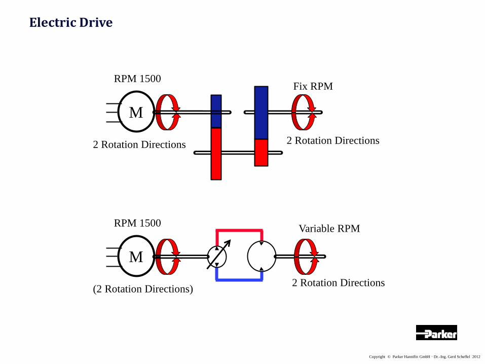
Electric Drive
Fix RPM
2 Rotation Directions
M
RPM 1500
2 Rotation Directions
Variable RPM
2 Rotation Directions
M
RPM 1500
(2 Rotation Directions)

Copyright © Parker Hannifin GmbH ◦ Dr.-Ing. Gerd Scheffel 2012
Electric Drive
Variable RPM
2 Rotation Directions
M
RPM 0 - 10000
2 Rotation Directions
Variable RPM
2 Rotation Directions
M
RPM 1500
(2 Rotation Directions) ?

Copyright © Parker Hannifin GmbH ◦ Dr.-Ing. Gerd Scheffel 2012
Electric Drive
? Variable RPM
2 Rotation Directions
RPM 0 - 3000
M
2 Rotation Directions
Variable RPM
2 Rotation Directions
M
RPM 0 - 10000
2 Rotation Directions

Copyright © Parker Hannifin GmbH ◦ Dr.-Ing. Gerd Scheffel 2012
Electric Drive – Linear Motion
Variable Speed
2 Directions
M
RPM 1500
(2 Rotation Directions)
Fix Speed
2 Directions
M
RPM 1500
2 Rotation Directions

Copyright © Parker Hannifin GmbH ◦ Dr.-Ing. Gerd Scheffel 2012
Electric Drive – Linear Motion
Variable Speed
2 Directions
M
RPM 1500
(2 Rotation Directions)
Variable Speed
2 Directions
M
RPM 0 - 10000
2 Rotation Directions

Copyright © Parker Hannifin GmbH ◦ Dr.-Ing. Gerd Scheffel 2012
Electric Drive – Linear Motion
Variable Speed
2 Directions
M
RPM 0 - 3000
2 Rotation Directions ?
Variable Speed
2 Directions
M
RPM 0 - 10000
2 Rotation Directions

Copyright © Parker Hannifin GmbH ◦ Dr.-Ing. Gerd Scheffel 2012
Electric Drive – Linear Motion
?
Variable Speed
2 Directions
M
RPM 0 - 10000
2 Rotation Directions
Variable Speed
2 Directions
M
RPM 0 - 3000
2 Rotation Directions

Copyright © Parker Hannifin GmbH ◦ Dr.-Ing. Gerd Scheffel 2012
Electric Drive – Linear Motion
? M
RPM 0 - 3000
2 Rotation Directions
Variable Speed
2 Directions
M
RPM 0 - 10000
2 Rotation Directions
Variable Speed
2 Directions

Copyright © Parker Hannifin GmbH ◦ Dr.-Ing. Gerd Scheffel 2012
Electric Drive – Linear Motion
M
? M
Variable Speed
2 Directions
M
RPM 0 - 10000
2 Rotation Directions
Copyright © Parker Hannifin GmbH ◦ Dr.-Ing. Gerd Scheffel 2012
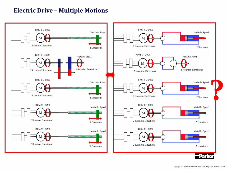
Electric Drive – Multiple Motions
?

Copyright © Parker Hannifin GmbH ◦ Dr.-Ing. Gerd Scheffel 2012
Electric Drive – Multiple Motions

Copyright © Parker Hannifin GmbH ◦ Dr.-Ing. Gerd Scheffel 2012
Electric Drive – Multiple Motions
P-port
T-port

Copyright © Parker Hannifin GmbH ◦ Dr.-Ing. Gerd Scheffel 2012
Partnering w Electromechanics

Copyright © Parker Hannifin GmbH ◦ Dr.-Ing. Gerd Scheffel 2012

Copyright © Parker Hannifin GmbH ◦ Dr.-Ing. Gerd Scheffel 2012
16 Motors x 500kW = 8 MW Power

Copyright © Parker Hannifin GmbH ◦ Dr.-Ing. Gerd Scheffel 2012
Reluctance Motor Permanent Magnet Motor
Induction Motor
Next Generation
Square Frame Induction Motor
w improved Dynamics

Copyright © Parker Hannifin GmbH ◦ Dr.-Ing. Gerd Scheffel 2012
Electric Drive – Linear Motion

Copyright © Parker Hannifin GmbH ◦ Dr.-Ing. Gerd Scheffel 2012
Gearbox Elimination Conversion Rotation to Linear
Electric Drive

Copyright © Parker Hannifin GmbH ◦ Dr.-Ing. Gerd Scheffel 2012
Application examples

Copyright © Parker Hannifin GmbH ◦ Dr.-Ing. Gerd Scheffel 2012
Peak Power = 1MW
Application examples

Copyright © Parker Hannifin GmbH ◦ Dr.-Ing. Gerd Scheffel 2012
Electric Drive – Single Linear Motion

Copyright © Parker Hannifin GmbH ◦ Dr.-Ing. Gerd Scheffel 2012
Electric Drive – Linear Motion

Copyright © Parker Hannifin GmbH ◦ Dr.-Ing. Gerd Scheffel 2012
Standard Circuit
Standard Circuit
Regenerative Cylinder Ratio 2:1
Electric Drive – Linear Motion

Copyright © Parker Hannifin GmbH ◦ Dr.-Ing. Gerd Scheffel 2012
A-Regenerative

Copyright © Parker Hannifin GmbH ◦ Dr.-Ing. Gerd Scheffel 2012
A-Regenerative
Copyright © Parker Hannifin GmbH ◦ Dr.-Ing. Gerd Scheffel 2012
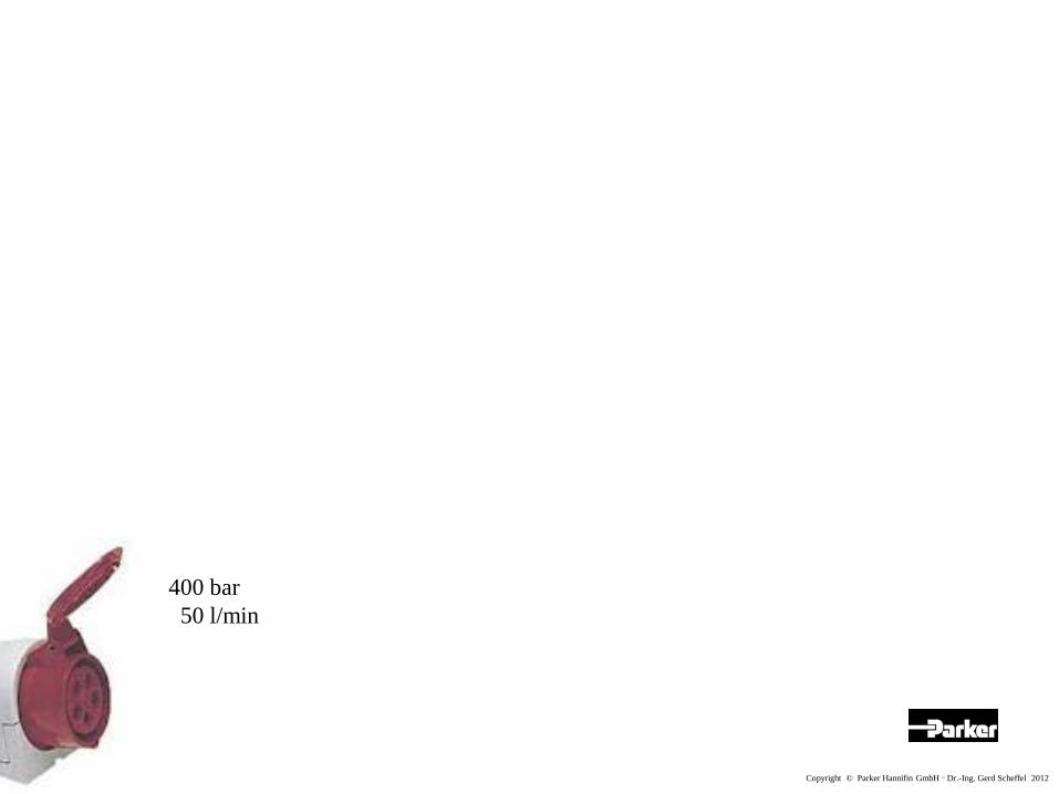
400 bar 50 l/min

Copyright © Parker Hannifin GmbH ◦ Dr.-Ing. Gerd Scheffel 2012
400 Volt 50 Hz
Electricity turns our World
M

Copyright © Parker Hannifin GmbH ◦ Dr.-Ing. Gerd Scheffel 2012
M
400 Volt 60 Hz
# Pole
Field RPM
Motor RPM
8 900 855
6 1200 1140
4 1800 1710
2 3600 3420
Induction Motor
Revolutions per Minute
Cycles per Second

Copyright © Parker Hannifin GmbH ◦ Dr.-Ing. Gerd Scheffel 2012
# Pole
Inverter RPM
8 0 - 1800
6 0 - 2400
4 0 - 3600
2 0 - 7200
M
400 Volt 60 Hz
400 Volt 0 - 120 Hz
DC
Diesel 1500/2000/2500
RPM too high, Torque too low
RPM too low
Induction Motor

Copyright © Parker Hannifin GmbH ◦ Dr.-Ing. Gerd Scheffel 2012
M
Permanent Magnet Motor Induction Motor
• Low Cost • < 1000 kW
• Turns w Field RPM • Higher Torque @ given Size • Better Efficiency • Servo = closed Loop for highest Dynamics • < 85 kW

Copyright © Parker Hannifin GmbH ◦ Dr.-Ing. Gerd Scheffel 2012
M
M M M M M

Copyright © Parker Hannifin GmbH ◦ Dr.-Ing. Gerd Scheffel 2012
Dis
plac
emen
t
Gear Vane Piston
External Internal Inline Bent Axis Radial
ccm
10 n/a 250-3000 300-3000 400-3000 50-4200 500-2800
50 n/a 250-2400 300-3000 400-2800 50-2800 500-2100
100 n/a 250-2200 300-3000 400-2300 50-2300 500-1800
250 n/a 250-2000 300-2200 400-1800 50-1500 n/a
M
RPM @ max pressure

Copyright © Parker Hannifin GmbH ◦ Dr.-Ing. Gerd Scheffel 2012
M
PElect. = n • MMech. MMech. = p • VDisp. P = Power M = Torque n = RPM p = Pressure V = Displacement

Copyright © Parker Hannifin GmbH ◦ Dr.-Ing. Gerd Scheffel 2012 Permanent Magnet Motor Frequency Inverter Internal Gear
• < 50 ccm w Motor controlling p & Q • Reverse Rotation for Decompression • High Bearing Load • Not repairable

Copyright © Parker Hannifin GmbH ◦ Dr.-Ing. Gerd Scheffel 2012 Induction Motor Frequency Inverter Internal Gear
• > 50 ccm w Motor controlling Q and Pressure Relief

Copyright © Parker Hannifin GmbH ◦ Dr.-Ing. Gerd Scheffel 2012 Permanent Magnet Motor Frequency Inverter Vane
• < 50 ccm w Motor controlling p & Q • Reverse Rotation for Decompression • No Bearings • Easy Repair through Cartridge Exchange

Copyright © Parker Hannifin GmbH ◦ Dr.-Ing. Gerd Scheffel 2012 Frequency Inverter Vane
• < 50 ccm w Motor controlling p & Q • Reverse Rotation for Decompression • No Bearings • Easy Repair through Cartridge Exchange
Permanent Magnet Motor

Copyright © Parker Hannifin GmbH ◦ Dr.-Ing. Gerd Scheffel 2012 Square Frame Induction Motor Frequency Inverter Vane
• > 50 ccm • Inertia of Motor + Pump Rotors limits Dynamics • Cavitation in Suction Line limits Dynamics • Shaft Torque limits Dynamics

Induction Motor Frequency Inverter Vane
• > 50 ccm • Inertia of Motor + Pump Rotors limits Dynamics • Cavitation in Suction Line limits Dynamics • Shaft Torque limits Dynamics

Induction Motor Frequency Inverter Vane 50 ccm Vane 125 ccm
• Double Pump in common Housing • Split Flow

Frequency Inverter Vane 50 ccm Vane 125 ccm
= max Motor Torque
• Double Pump in common Housing • Split Flow
Induction Motor

M Variable Piston Frequency Inverter
• 4 Quadrant Piston Pump • Decompression w Pump
Induction Motor

M Variable Piston Frequency Inverter
• Pressure compensated Piston Pump • Decompression w joined Pressure Relief
Induction Motor

M Variable Piston Frequency Inverter
@ full Stroke
• Pressure compensated Piston Pump • Pump to run full Stroke down to min RPM
Induction Motor

M Vane Variable Piston Frequency Inverter
Vane T7D 137,5 ccm
Variable Piston PV 140
4 kW
0,2 – 0,8 kW
7 kW
14 kW
Square Frame Induction Motor
@ 300 bar 2000 RPM

M Vane110 ccm Variable Piston 140 ccm Frequency Inverter
@ min RPM @ max RPM
= max Motor Torque
• Fix and variable Pump Combination
Square Frame Induction Motor
Copyright © Parker Hannifin GmbH ◦ Dr.-Ing. Gerd Scheffel 2012
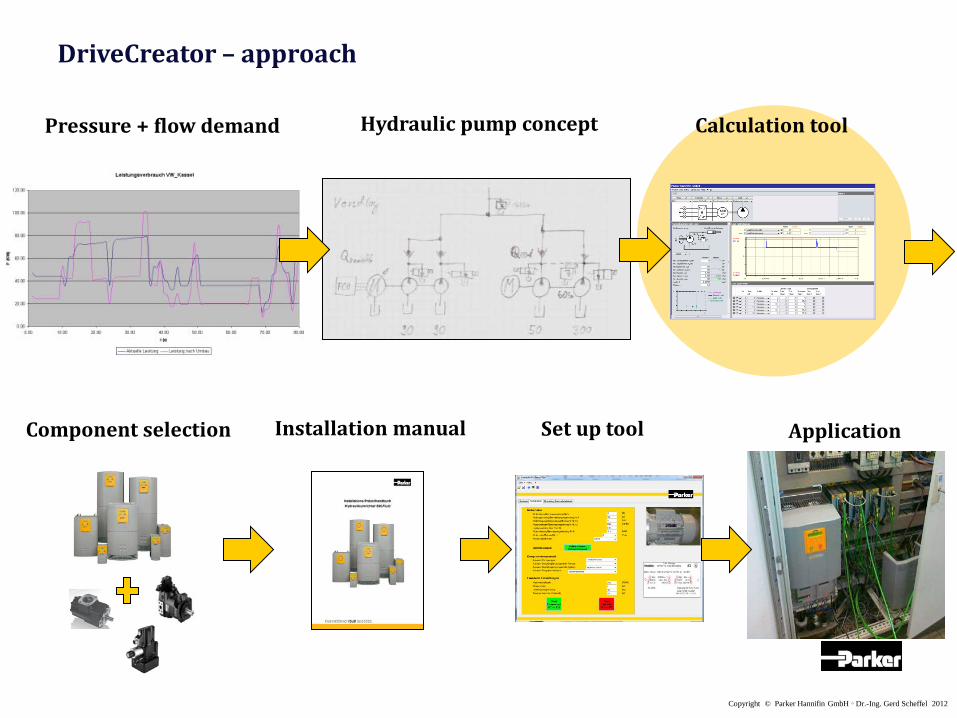
Calculation tool
Component selection Set up tool
Pressure + flow demand Hydraulic pump concept
Installation manual Application
DriveCreator – approach

Copyright © Parker Hannifin GmbH ◦ Dr.-Ing. Gerd Scheffel 2012
Drive selection Max. current
Motor selection Torque, lowest energy input
Pump selection Smallest possible pump size
User input Load cycle p/Q(t)
DriveCreator – approach

Copyright © Parker Hannifin GmbH ◦ Dr.-Ing. Gerd Scheffel 2012
DriveCreator – overview
• Offline & Internet version
• Wizard based
• One page design
• Database support (pump, motor and inverter )
• Sizing of pump, motor and inverter
• Plausibility check of user input
• Single and double pumps
• Induction Motor and Permanent Magnet Motor technology
• Motor temperature calculation
• Efficiency comparison inverter vs grid

Copyright © Parker Hannifin GmbH ◦ Dr.-Ing. Gerd Scheffel 2012
Katalogangabe Katalogangabe Katalogangabe Katalogangabe Katalogangabe Katalogangabe
Name Fördermenge
[cm³/U]
Norminaldruck
[bar] Maximaldruck
[bar]
Bemessungsdrehzahl
[1/min]
Min Drehzahl [1/min]
Max Drehzahl [1/min]
Massenträgheits-moment
[kgm²]
Name Displacement
cm³/rev Nominal
pressure [bar] Max. pressure
[bar] Rated speed [rpm]
Min. rotation
speed [rpm]
Max. rotation speed [rpm] Inertia [kgm²]
PV016 16 350 420 1500 300 3000 0.0017 PV046 46 350 420 1500 300 2800 0.0043 PV092 92 350 420 1500 300 2300 0.018 PV180 180 350 420 1500 300 2200 0.03 PV270 270 350 420 1500 300 1800 0.098
T7BB05 15.9 290 320 1500 600 3600 0.0032 T7BB10 31.8 290 320 1500 600 3600 0.0032 T7BB15 50 240 280 1500 600 3000 0.0032
0 10
20 30
40 50
60 70
0.1 0.2
0.3 0.4
0.5 0.6
0.7 0.8
0.9 1
-0.2
0
0.2
0.4
0.6
0.8
1
z
Function
f
y
z
ηpump
pump data base
DriveCreator – pump sizing

Copyright © Parker Hannifin GmbH ◦ Dr.-Ing. Gerd Scheffel 2012
DriveCreator – pump sizing

Copyright © Parker Hannifin GmbH ◦ Dr.-Ing. Gerd Scheffel 2012
DriveCreator – pump sizing

Copyright © Parker Hannifin GmbH ◦ Dr.-Ing. Gerd Scheffel 2012
DriveCreator – motor sizing
ηe
pve

Copyright © Parker Hannifin GmbH ◦ Dr.-Ing. Gerd Scheffel 2012
DriveCreator – motor sizing

Copyright © Parker Hannifin GmbH ◦ Dr.-Ing. Gerd Scheffel 2012
DriveCreator – drive sizing

Copyright © Parker Hannifin GmbH ◦ Dr.-Ing. Gerd Scheffel 2012
DriveCreator – drive sizing

• F690p / AC30F / Compax3 – drive with hydraulic function
• Induction motor • Permanent magnet motor
• Pump + valve
• Assembled
• Tested
+ + +
+ + +
+
+
+
+
DriveCreator – packages

•Input motor data according to name plate
•Test of direction at low speed
•Component selection of pump
and pressure relief valve
•Program function:
• Accu charging
• p/Q control
• …
•Configuration download
DriveCreator – set up tool

Application examples

Copyright © Parker Hannifin GmbH ◦ Dr.-Ing. Gerd Scheffel 2012
Starting with the End in Mind
• Saving energy > only needed power for the motor > smaller components > higher efficiency > less fluid cooling • Reducing noise > noise only @ high demand
• Increasing power density > higher delivery @ same frame size
Copyright © Parker Hannifin GmbH ◦ Dr.-Ing. Gerd Scheffel 2012
Presented by Dr.-Ing. Gerd Scheffel
Energy Efficient Hydraulics
Variable Frequency Drives as Pump Prime Movers