Embed Size (px)
Citation preview

Energy Efficient Arrival with RTA Constraint for
Urban eVTOL Operations
Priyank Pradeep ∗ Peng Wei †
The electric vertical takeoff and landing (eVTOL) air taxis can alleviate transportationcongestion on the ground by utilizing three-dimensional airspace efficiently. However, theendurance of Lithium-ion Polymer (Li-Po) batteries imposes severe constraints on theoperational time span of an eVTOL vehicle on an urban air mobility (UAM) passengertransport mission. This research focuses on the formulation of fixed final time multiphaseoptimal control problem with energy consumption as the performance index for a multirotoreVTOL vehicle. The proposed multiphase optimal control problem formulation and thenumerical solution enables the eVTOL air taxi to meet the given required time of arrival(RTA) and achieve the most energy efficient arrival trajectory, which is a critical enablerfor the safe and efficient future eVTOL operations for passenger transportation and cargodelivery. The problem formulation is validated in a UAM passenger transport use casewith EHang 184 eVTOL air taxi and an Uber proposed vertiport in numerical simulations.However, this proposed framework can also be used to address an energy efficient cargodelivery case in a UAS traffic management (UTM) context.
Nomenclature
A Rotor disk areaD Drag forceFx Equivalent front plate area of the fuselage of the eVTOL air taxiFh Equivalent top plate area of the fuselage of the eVTOL air taxih Altitude of the vehicleJ Optimal control performance indexm Mass of the vehicleP PowerR Radius of the rotorT Thrust forcevh Rotor induced velocity in hover(vh)e Co-axial rotor system effective induced velocity in hovervi Rotor induced velocity during forward flightV True airspeed of the eVTOL air taxiVx Component of true airspeed along trackVh Component of true airspeed along vertical directionx Along track distance of the vehicle from the destinationα Angle of attack of air-stream relative to rotor tip path planeγ Aerodynamic flight path angleη Aerodynamic efficiency factorθ Rotor tip-path-plane pitch angleρ Density of the airωi Angular velocity of the ith rotor
∗Ph.D. Student, Aerospace Engineering Department, Iowa State University, Ames, IA, 50011†Assistant Professor, Aerospace Engineering Department, Iowa State University, Ames, IA, 50011
1 of 13
American Institute of Aeronautics and Astronautics
I. Introduction
Every day, millions of man hours are spent unproductively in cities across the world due to road-trafficcongestion. In 2014, the congestion caused 3.1 billion gallons of extra fuel burn in the US. Transportation as awhole accounted for approximately 33 % of CO2 emissions in the US, of which 80 % are from cars and truckstraveling on roadway system.1 A study in the American Journal of Preventative Medicine, for example,found that those who commute more than 10 miles were at increased odds of elevated blood pressure.2
The air taxis can alleviate transportation congestion on the ground by utilizing three-dimensional airspaceefficiently, just as skyscrapers allowed cities to use limited land more efficiently. A network of small, electricaircraft that take off and land vertically (eVTOL), can enable rapid and reliable transportation betweensuburbs and cities and, ultimately, within cities.3 The eVTOLs, can travel toward their destination on ageodesic path, making route-based congestion less prevalent. Over a dozen companies, with many differentdesign approaches, are passionately working to make eVTOLs a reality. The eVTOLs have zero operationalemissions as they use electric propulsion.3–5
In this paper, we present a framework to perform energy efficient arrival for a multirotor urban eVTOLoperations given the required time of arrival (RTA) constraint. With the proposed multiphase optimal controlproblem formulation and the numerical solution, we enable the eVTOL air taxi to meet the given RTA andachieve the most energy efficient arrival trajectory, which is a critical enabler for the safe and efficient futureeVTOL operations for passenger transportation and cargo delivery. Our problem formulation is validated inan urban air mobility (UAM) passenger transport use case with EHang 184 eVTOL air taxi and an Uberproposed vertiport in numerical simulations. However, this proposed framework can also be used to addressan energy efficient cargo delivery case in an unmanned aircraft systems (UAS) traffic management (UTM)context.
II. Background and Motivation
A. Background
Since 2013, NASA4 and its collaborators from government, industry, and academia have contributed tothe research and development of UAS traffic management (UTM). They have been focused on small UASoperations, which include cargo delivery proposed by Amazon and Google. However, from 2016 onwardsthe possibility of urban air mobility (UAM) has also been explored by NASA, Uber, Airbus and universityresearchers.3–6
Most of the UTM and UAM operations of the eVTOL air taxis are under limited battery endurance andvertiport capacity. A few groups such as in Georgia Tech, Purdue University, NASA Ames, and PolytechnicUniversity of Catalonia have worked on commercial jetliners continuous descent operations for energy efficientarrival.7–14 However, according to our knowledge, no significant research work has been carried out for theenergy efficient arrival under time constrained environment for the eVTOL air taxis in the UTM or UAMcontext. This paper aims to fill this gap to enable safe and efficient eVTOL operations given limited vertiportcapacity and eVTOL battery endurance.
B. Motivation
Though electric propulsion is the preferred propulsion choice for the VTOL air taxi, the specific energy (theamount of energy per unit weight provided by the battery) of Lithium-ion polymer (LiPo) batteries today isinsufficient for long-range commutes.3 Also, from the certification point of view eVTOL aircraft may requirelanding with reserve battery charge/usage time (analogous to reserve fuel in the aircraft).
The research effort on UAS traffic management (UTM) and urban air mobility (UAM), need to addressthe following two critical operational challenges for cargo delivery and passenger transportation by theeVTOL air taxis:(i) Generate the optimal energy efficient arrival trajectory given limited battery endurance.(ii) Satisfy the RTA constraint given the safe aircraft separation and limited vertiport arrival time slots.
Therefore, optimal (minimum battery usage) trajectory generation with RTA constraint is one of the keyelements for the operational success of the eVTOL air taxis.
2 of 13
American Institute of Aeronautics and Astronautics

III. Problem Formulation
A. Vehicle Model
The eVTOL air taxi is modeled based on specifications of EHang 184.15The vehicle has four arms (4X-configuration) with each arm consisting of two identical coaxial counter-rotating rotors. The rotor tip-path-plane is assumed to be parallel to the horizontal plane of the vehicle.
Figure 1. EHang 184: coaxial multi-rotor eVTOL air taxi with X8-configuration15
Figure 2. Top view of EHang 184, all dimensions in mm15
B. Trajectory Optimization
The lateral path between the initial position of the eVTOL in-air (cruise phase) and the vertiport is assumedto be a geodesic path. Therefore, only the vertical trajectory of the eVTOL air taxi is free for the opti-mization. However, since the arrival time constraint has been imposed on the eVTOL vehicle, the probleminvolves generation of an energy-optimal vertical path for the eVTOL vehicle under arrival time constraint.
C. Flight Dynamics Model
In quadrotors roll, pitch and yaw angles are controlled by using various differential thrust mechanism acrossthe rotors. For example, differential thrust between opposite motors provides roll and pitch moments.16
Previously, researchers17–19 have successfully decoupled longitudinal and lateral dynamics for helicopterswith the conventional design. In general, quadrotors have a more symmetrical design (the location of rotors
3 of 13
American Institute of Aeronautics and Astronautics
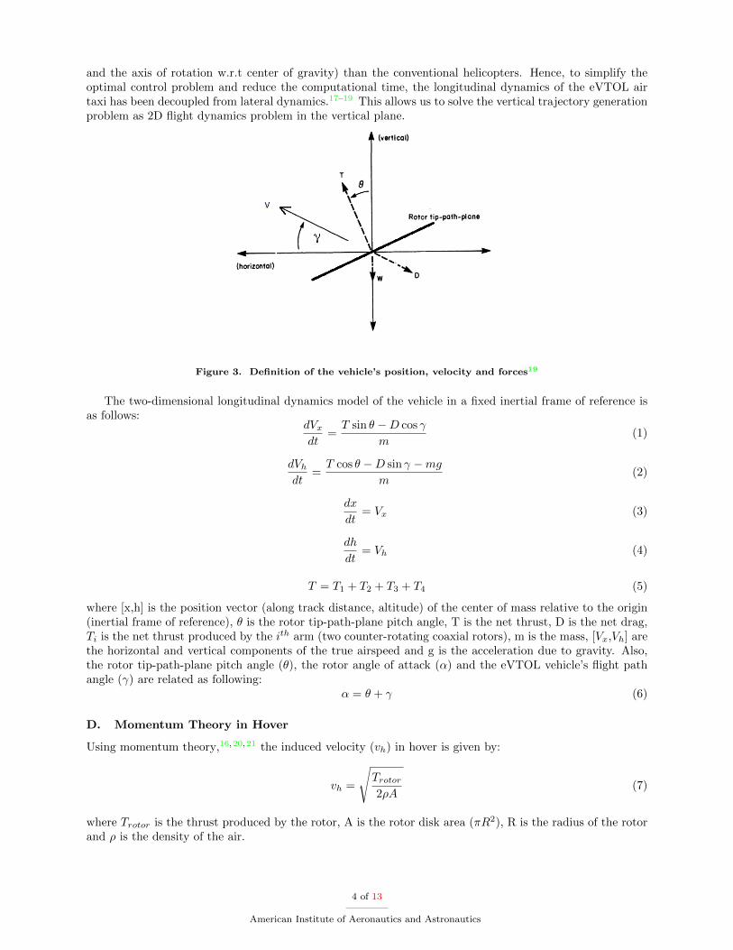
and the axis of rotation w.r.t center of gravity) than the conventional helicopters. Hence, to simplify theoptimal control problem and reduce the computational time, the longitudinal dynamics of the eVTOL airtaxi has been decoupled from lateral dynamics.17–19 This allows us to solve the vertical trajectory generationproblem as 2D flight dynamics problem in the vertical plane.
Figure 3. Definition of the vehicle’s position, velocity and forces19
The two-dimensional longitudinal dynamics model of the vehicle in a fixed inertial frame of reference isas follows:
dVxdt
=T sin θ −D cos γ
m(1)
dVhdt
=T cos θ −D sin γ −mg
m(2)
dx
dt= Vx (3)
dh
dt= Vh (4)
T = T1 + T2 + T3 + T4 (5)
where [x,h] is the position vector (along track distance, altitude) of the center of mass relative to the origin(inertial frame of reference), θ is the rotor tip-path-plane pitch angle, T is the net thrust, D is the net drag,Ti is the net thrust produced by the ith arm (two counter-rotating coaxial rotors), m is the mass, [Vx,Vh] arethe horizontal and vertical components of the true airspeed and g is the acceleration due to gravity. Also,the rotor tip-path-plane pitch angle (θ), the rotor angle of attack (α) and the eVTOL vehicle’s flight pathangle (γ) are related as following:
α = θ + γ (6)
D. Momentum Theory in Hover
Using momentum theory,16,20,21 the induced velocity (vh) in hover is given by:
vh =
√Trotor2ρA
(7)
where Trotor is the thrust produced by the rotor, A is the rotor disk area (πR2), R is the radius of the rotorand ρ is the density of the air.
4 of 13
American Institute of Aeronautics and Astronautics
E. Momentum Theory in Forward Flight
Consider a rotorcraft in forward motion at true airspeed V , with angle of attack α between the air-streamand the rotor disk (tip path plane). The solution for induced velocity (vi) is:16,20,21
vi =v2h√
(V cosα)2 + (V sinα+ vi)2(8)
The thrust produced by the ideal rotor per power input:16,20,21
Trotor =Protor
V sinα+ vi(9)
F. Coaxial Rotor Interference in Forward Flight
The eVTOL air taxi under consideration has 4 arms, with each arm consisting of two identical counter-rotating rotors. Assuming equal thrust produced by the lower and upper rotors of the coaxial rotor system,the net thrust produced by the arm is given by:
Tarm = Tlower + Tupper = 2Trotor (10)
Wing theory for a single lifting surface shows that the induced power loss of the arm i.e. coaxial counter-rotating system is:21
Parm = 2Pinduced(1 + χ) (11)
where Pinduced is the induced power of an isolated rotor and χ is the rotor interference factor for the coaxialrotor system. Typically, χ is ≤ 1. However, in the current research the interference factor (χ) for all therotors is assumed to be 1.0.21
G. Drag Model
Based on the maximum ground speed of the vehicle (100 km/hr), the vehicle operates in M < 0.3 flow regimeand hence the drag force on the fuselage of the eVTOL air taxi can be modeled based on the incompressibleflow theory. The net drag on the vehicle is assumed to be equivalent to the drag on the fuselage of thevehicle. Therefore, the net drag on the vehicle is calculated as follows:18,22
D =ρV 2CDF
2(12)
where F is the equivalent flat plate area of the fuselage and CD = 1.18 The horizontal and vertical componentsof the drag in fixed inertial frame of reference are as follows:
Dx =ρV 2
x CDFx2
(13)
Dh =ρV 2
hCDFh2
(14)
where Fx and Fh are the equivalent front and top flat plate area of the fuselage respectively.
H. Power Required by the eVTOL Vehicle
Energy balance equation for a multirotor eVTOL vehicle is given by:18,23
N∑i=1
Iiωidωidt
=
N∑i=1
Pi − Prequired (15)
where Pi is the energy supplied to the ith rotor, Prequired is the instantaneous power required by the vehicle(to overcome induced drag, profile drag, parasite drag and/or gravity to climb), ωi is the rotational speedof the ith rotor and Ii is the rotational moment of inertia of the ith rotor. However, based on assumption of
5 of 13
American Institute of Aeronautics and Astronautics

quasi-steady flight in the current research, the instantaneous power required in forward flight is equal to thesum of the induced power, parasite power, climb power and profile power.20,21,24
Prequired = Pinduced + Pparasite + Pclimb + Pprofile (16)
The profile power exhibits only a slight increase in value with forward speed unless the tip of the rotoris above the critical Mach number.21 Since the eVTOL vehicle considered in this research is a low speedvehicle with a small rotor diameter (1.6 m), the profile drag is assumed to be constant in magnitude andhence has a negligible impact on the variation of the instantaneous power required. Therefore, in the currentresearch Prequired is assumed to be:21
Prequired = Pinduced + Pparasite + Pclimb (17)
Prequired = 4Parm + TV sinα (18)
where Parm is the induced power loss per arm i.e. coaxial rotors and the term TV sinα is the power requiredto climb and to propel the eVTOL vehicle forward (the parasite power loss).21
I. Performance Index of Multiphase Optimal Control
The power supplied by the battery to the ideal ith motor at time t is given by:16
Pi(t) = Vi(t)Ii(t) (19)
where Vi(t) and Ii(t) is the instantaneous voltage and current across the motor respectively.16,25 Therefore,by equating the total energy supplied by the battery (or pack of batteries) to the ideal power consumed byall the motors (8 in total), the power consumed by the motors is given by:
P (t) =
8∑i=1
Vi(t)Ii(t) (20)
Hence from the above equation, we can see that in order to minimize battery usage the following perfor-mance index needs to be minimized (the Lagrange type problem):
J =
∫ tf
0
8∑i=1
Vi(t)Ii(t)dt (21)
The performance index of multiphase optimal control problem for the vertical trajectory optimization ofthe eVTOL vehicle is as follows:
J =
2∑N=1
∫ tNf
tN0
8∑i=1
Vi(t)Ii(t)dt (22)
where N is the vertical flight phase (N = 1 for cruise and N = 2 for descent(arrival)).Assuming that the power supplied by the battery pack is equal to the power required (induced and
parasite), ignoring the profile power, the performance index for the vertical trajectory optimization of theeVTOL vehicle is:
J =
2∑N=1
∫ tNf
tN0
(
4∑Arm=1
Parm(t) + TV sinα)dt (23)
J. Bounds on State and Control Variables
The eVTOL air taxi’s pitch angle is assumed to be bounded to 6◦ for passenger comfortness based ondiscussions with NASA researchers and experienced helicopter pilots.
−6◦ ≤ θfuselage ≤ 6◦ (24)
6 of 13
American Institute of Aeronautics and Astronautics

The maximum speed (m/s), maximum cruise altitude (m) and total power (KW) is bounded based onspecifications of EHang 18415
0 ≤ Vx ≤ 27.778 (25)
0 ≤ h ≤ 3500 (26)
P ≤ 152 (27)
The cruise phase transitions to descent phase at Top of Descent (TOD) waypoint. Hence, TOD i.e. phasetransition waypoint is subject to phase link constraints on state variables (X) apart from path and controlconstraints26,27 :
XN−1(tN−1f ) = XN (tN0 ) (28)
In our initial effort, airspace restrictions on the speed and altitude of the vehicle have been ignored.However, our framework allows us to easily modify bounds on the state and control variables based on newresearch findings about passenger comfort ability and operational requirements.
K. Avoidance of Vortex Ring State in Descent
When a multi-rotor vehicle starts to descend from the cruise phase, the flow starts to develop recirculationnear the disk and turbulence above it.21,28 However, at small rates of descent, the flow in the vicinity of thedisk is still reasonably well represented by the momentum theory model.
In vortex ring state, the flow near the rotor disk becomes highly unsteady and turbulent. Hence, therotor in this state experiences a very high vibration level and loss of control. In order, to avoid the eVTOLvehicle entering into vortex ring state, the following constraint has been imposed to the descent phase of theproblem:21,28
−0.28 ≤ V sinα
(vh)e≤ 0 (29)
(vh)e =
√2Trotor
2ρA(30)
where V is the true airspeed of the eVTOL vehicle, Trotor is the thrust produced by the upper/lower rotorof the co-axial rotor system, (vh)e is the effective induced velocity in hover of the co-axial rotor system andα is the angle of attack of the tip path plane of the rotors.
L. Required Time of Arrival
Studies and operational trials have been undertaken to investigate the performance and behavior of RequiredTime of Arrival (RTA) function for the fixed-wing aircraft. RTA enables speed control of the aircraft tomeet a Controlled Time of Arrival imposed by Air Traffic Control (ATC).29 We anticipate implementationof RTA in the trajectory optimization (4D) of eVTOL air taxis would be critical to the traffic managementof air taxis in future. In the current research, RTA is imposed as final time constraint on the eVTOL vehicle(EHang 184). Hence, the vertical trajectory optimization problem involves fixed tf and position [xf , hf ].
tf = RTA (31)
M. Autorotation in Descent
The power-off descent of a rotorcraft is called autorotation. The climb/cruise longitudinal flight dynamicsmodel cannot be exactly used for autorotative descent. As in power-off descent, the airstream velocity isdirected upward and therefore the far downstream wake is above the rotor disk.21 For forward descent inpower-off state, |V sinα
Vh| > 2 safely avoids power settling for any glide slope angle:16,20,21 Typically, classical
momentum theory can also be applied to forward descent when V sinαVh
< -2 (windmill braking state):
vivh
= −V sinα
2vh−
√(V sinα)2
4v2h− 1 (32)
7 of 13
American Institute of Aeronautics and Astronautics

Figure 4. Force and velocity vectors during autorotation20
IV. Numerical Study
The equations of motion of the multi-rotor eVTOL vehicle (EHang 184) are continuous-time nonlin-ear differential equations which are difficult to solve analytically. For this reason, the vertical trajectoryoptimization problems are numerically solved using a pseudospectral method. Pseudospectral methods tran-scribe a multiphase optimal control problem to a large sparse nonlinear programming problem (NLP).26,27
We used GPOPS-II26,27 for transcribing the eVTOL’s optimal control problems to the corresponding NLPsusing hp-adaptive Gaussian quadrature collocation, these NLPs were then solved using IPOPT.26,27,30
As EHang 184 is a short range and slow speed eVTOL vehicle,3 the starting point for the fixed final timearrival trajectory optimization problem has been chosen as 20 km along-track distance from the vertiport.For the case study 1 and 2, the initial condition (IC) and final condition (FC) for the multiphase optimalcontrol problems are as shown in Table 1. Since the initial altitude and final altitude of the eVTOL vehicleare greater than 2Radiusrotor the in-ground effect (IGE) is neglected.21
Table 1. Initial and Final Conditions
State Variable IC FC
Altitude (m) 500 5
Along-track distance (m) 0 20000
Time (s) 0 RTA (tf )
The performance data of EHang 184 used for aerodynamics and momentum theory related computationsare as shown in Table 2.
Table 2. Performance Data
Variable Value
Rotor Diameter (m) 1.6
Mass (kg) 240
Equivalent Front Plate Area (m2) 2.11
Equivalent Top Plate Area (m2) 1.47
8 of 13
American Institute of Aeronautics and Astronautics
A. Case Study 1: Energy Efficient Vertical Trajectories of the Fixed Pitch eVTOL Vehicle
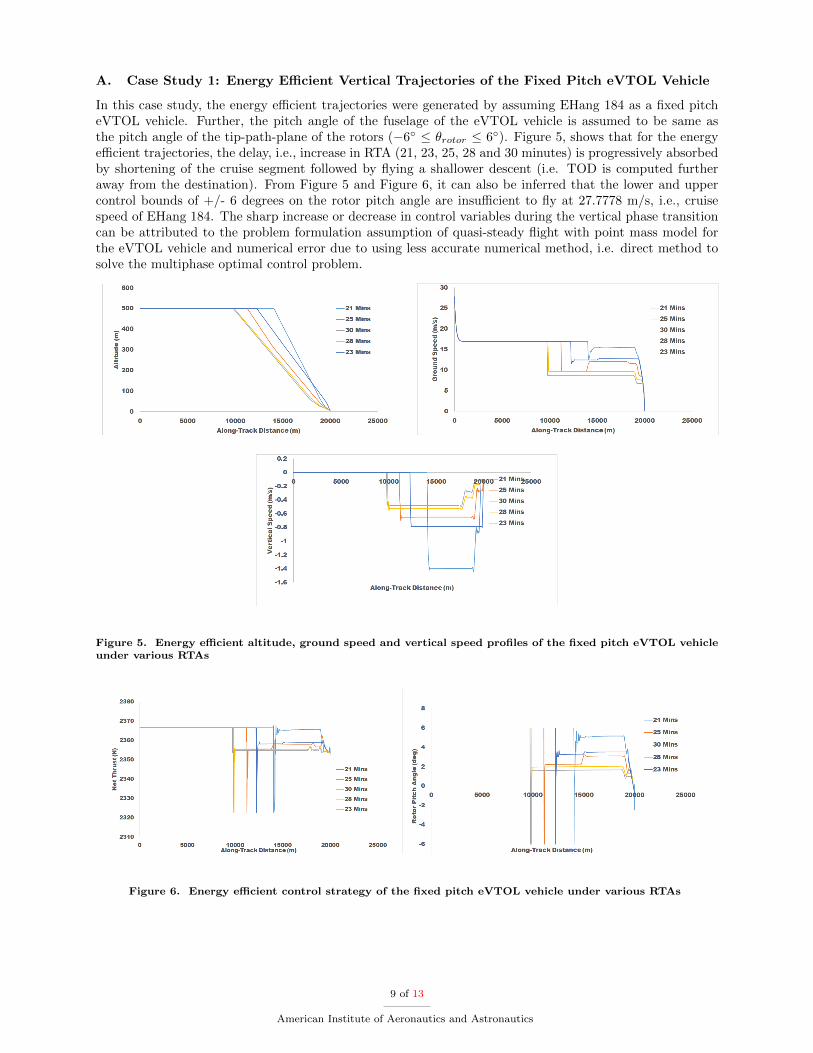
In this case study, the energy efficient trajectories were generated by assuming EHang 184 as a fixed pitcheVTOL vehicle. Further, the pitch angle of the fuselage of the eVTOL vehicle is assumed to be same asthe pitch angle of the tip-path-plane of the rotors (−6◦ ≤ θrotor ≤ 6◦). Figure 5, shows that for the energyefficient trajectories, the delay, i.e., increase in RTA (21, 23, 25, 28 and 30 minutes) is progressively absorbedby shortening of the cruise segment followed by flying a shallower descent (i.e. TOD is computed furtheraway from the destination). From Figure 5 and Figure 6, it can also be inferred that the lower and uppercontrol bounds of +/- 6 degrees on the rotor pitch angle are insufficient to fly at 27.7778 m/s, i.e., cruisespeed of EHang 184. The sharp increase or decrease in control variables during the vertical phase transitioncan be attributed to the problem formulation assumption of quasi-steady flight with point mass model forthe eVTOL vehicle and numerical error due to using less accurate numerical method, i.e. direct method tosolve the multiphase optimal control problem.
Figure 5. Energy efficient altitude, ground speed and vertical speed profiles of the fixed pitch eVTOL vehicleunder various RTAs
Figure 6. Energy efficient control strategy of the fixed pitch eVTOL vehicle under various RTAs
9 of 13
American Institute of Aeronautics and Astronautics

B. Case Study 2: Energy Efficient Vertical Trajectories of the Collective Pitch eVTOL Vehicle
The results of this case study were generated without imposing control bounds on the pitch angle of thetip-path-plane of the rotors, and the eVTOL vehicle is assumed to have a collective pitch mechanism. Figure7 and Figure 8, shows that for the energy efficient trajectories, like in case study 1, the delay is absorbedby shortening of the cruise segment followed by flying a shallower descent (i.e. TOD is computed furtheraway from the destination). However, unlike the case study 1, the optimal ground speed for the cruisesegment is computed as 27.7778 m/s, i.e., EHang 184’s cruise speed. As stated before, the sharp increase ordecrease in control variables during the vertical phase transition can be attributed to the problem formulationassumption of quasi-steady flight with point mass model for the eVTOL vehicle and numerical error due tousing less accurate numerical method, i.e. direct method to solve the multiphase optimal control problem.
Figure 7. Energy efficient altitude, ground speed and vertical speed profiles of the collective pitch eVTOLvehicle under various RTAs
Figure 8. Energy efficient control strategy of the collective pitch eVTOL vehicle under various RTAs
10 of 13
American Institute of Aeronautics and Astronautics

C. Case Study 3: Effect of Cruise Altitude on Efficiency
The energy consumption results of the eVTOL vehicle at various cruise altitudes were computed by inte-grating the instantaneous power required for 20 minutes flight duration in cruise phase. As shown in Figure9, the energy consumption of the eVTOL vehicle increases with increase in the cruise altitude for the sameset of conditions (cruise speed, flight duration, and mass). The energy consumption results have the inducedpower loss as the dominant contributor of the two (induced and parasite) at the cruise speed of EHang 184.However, we anticipate in future with the possible increase in the operational cruise speed of a multirotoreVTOL vehicle like EHang 184, the cruise efficiency will improve with increase in the cruise altitude becauseof the reduction in the parasite drag (dominant contributor to the power loss at high speed) with increasein the altitude.
Figure 9. Energy consumption vs cruise altitude for the eVTOL vehicle
V. Conclusions
In this research, multiphase optimal control problem with energy consumption as the performance indexis formulated for a multirotor eVTOL vehicle on an urban air mobility (UAM) passenger transport mission.Further, we present a framework to perform energy efficient arrival for a multirotor urban eVTOL air taxigiven the required time of arrival (RTA) constraint. However, this proposed framework can also be used toaddress an energy efficient cargo delivery case in a UAS traffic management (UTM) context.
The formulated vertical trajectory optimization problem was numerically solved using pseudospectralmethod for a specific eVTOL vehicle, i.e., EHang 184. The numerical results of the fixed pitch case studysuggest that the collective pitch mechanism is required for the operational feasibility of a multirotor eV-TOL vehicle like EHang 184 considering passenger comfortness. Further, by imposing various arrival timeconstraints on the eVTOL vehicle, we found that for the energy efficient arrival operations, delay is bestabsorbed by shortening of the cruise segment followed by flying a shallower descent (i.e. TOD is computedfurther away from the destination). Also, the energy consumption case study shows that the cruise efficiencyof EHang 184 drops with the increase in the cruise altitude. The energy consumption results also show thatthe induced power loss is the dominant contributor of the two (induced and parasite) at the cruise speed ofEHang 184. We anticipate in future with the possible increase in the operational cruise speed of a multirotoreVTOL vehicle like EHang 184, the cruise efficiency will improve with increase in the cruise altitude becauseof the reduction in the parasite drag (dominant contributor to the power loss at high speed) with an increasein the altitude.
VI. Future Work
In our future work, we will consider the following: (i) vertical trajectory optimization of a multirotoreVTOL air taxi under wind impact; (ii) trajectory optimization of a tandem tilt-wing eVTOL; (iii) arrivalscheduling of multiple eVTOL air taxis.
11 of 13
American Institute of Aeronautics and Astronautics

VII. Acknowledgment
The authors would like to specially thank Hokkwan Ng and Gilbert Wu at NASA Ames Research Centerfor their technical reviews and valuable recommendations. We would also like to thank Eric Mueller andParimal Kopardekar at NASA Ames Research Center, Karthik Balakrishnan at Airbus A3, and Jon Petersenand Mark Moore at Uber Elevate for the inspiring and encouraging discussions.
References
1Schrank, D., Eisele, B., Lomax, T., and Bak, J., “2015 urban mobility scorecard,” 2015.2Hoehner, C. M., Barlow, C. E., Allen, P., and Schootman, M., “Commuting distance, cardiorespiratory fitness, and
metabolic risk,” American journal of preventive medicine, Vol. 42, No. 6, 2012, pp. 571–578.3Uber-Elevate, “Fast-forwarding to the future of on-demand, urban air transportation,” https://www.uber.com/, 2017,
[Online; accessed 19-November-2017].4Prevot, T., Rios, J., Kopardekar, P., Robinson III, J. E., Johnson, M., and Jung, J., “UAS traffic management (UTM)
concept of operations to safely enable low altitude flight operations,” 16th AIAA Aviation Technology, Integration, and Oper-ations Conference, 2016, p. 3292.
5Airbus-A3, “Future of urban mobility,” http://www.airbus.com/newsroom/news/en/2016/12/My-Kind-Of-Flyover.
html/.6Altawy, R. and Youssef, A. M., “Security, Privacy, and Safety Aspects of Civilian Drones: A Survey,” ACM Transactions
on Cyber-Physical Systems, Vol. 1, No. 2, 2016, pp. 7.7Park, S. G. and Clarke, J.-P., “Vertical trajectory optimization for continuous descent arrival procedure,” AIAA Guidance,
Navigation, and Control Conference, 2012, p. 4757.8Robinson III, J. E. and Kamgarpour, M., “Benefits of continuous descent operations in high-density terminal airspace
under scheduling constraints,” .9Clarke, J.-P. B., Ho, N. T., Ren, L., Brown, J. A., Elmer, K. R., Tong, K.-O., and Wat, J. K., “Continuous descent
approach: Design and flight test for Louisville International Airport,” Journal of Aircraft , Vol. 41, No. 5, 2004, pp. 1054–1066.10Pradeep, P. and Wei, P., “Predictability, variability and operational feasibility aspect of CDA,” Aerospace Conference,
2017 IEEE , IEEE, 2017, pp. 1–14.11Jin, L., Cao, Y., and Sun, D., “Investigation of potential fuel savings due to continuous-descent approach,” Journal of
Aircraft , Vol. 50, No. 3, 2013, pp. 807–816.12Cao, Y., Kotegawa, T., and Post, J., “Evaluation of continuous descent approach as a standard terminal airspace
operation,” .13Dalmau, R., Verhoeven, R., de Gelder, N., and Prats, X., “Performance comparison between TEMO and a typical FMS
in presence of CTA and wind uncertainties,” 2016 IEEE/AIAA 35th Digital Avionics Systems Conference (DASC), Sept 2016,pp. 1–8.
14Coppenbarger, R. A., Mead, R. W., and Sweet, D. N., “Field evaluation of the tailored arrivals concept for datalink-enabled continuous descent approach,” Journal of Aircraft , Vol. 46, No. 4, 2009, pp. 1200.
15EHang-184, “EHANG 184 autonomous aerial vehicle specs,” http://www.ehang.com/ehang184/specs/, 2017, [Online;accessed 06-June-2017].
16Hoffmann, G., Huang, H., Waslander, S., and Tomlin, C., “Quadrotor helicopter flight dynamics and control: Theoryand experiment,” AIAA Guidance, Navigation and Control Conference and Exhibit , 2007, p. 6461.
17Bottasso, C. L., Croce, A., Leonello, D., and Riviello, L., “Rotorcraft trajectory optimization with realizability consider-ations,” Journal of Aerospace Engineering, Vol. 18, No. 3, 2005, pp. 146–155.
18Yomchinda, T., Horn, J., and Langelaan, J., “Flight path planning for descent-phase helicopter autorotation,” AIAAGuidance, Navigation, and Control Conference, 2011, p. 6601.
19Johnson, W., “Helicopter optimal descent and landing after power loss,” 1977.20Heyson, H. H., “A momentum analysis of helicopters and autogyros in inclined descent, with comments on operational
restrictions,” 1975.21Johnson, W., Helicopter theory, Courier Corporation, 2012.22DeMoss, J. A., Drag measurements on an ellipsoidal body, Ph.D. thesis, Virginia Tech, 2007.23Pradeep, P., Park, S. G., and Wei, P., “Trajectory Optimization of Multirotor Agricultural UAVs,” to appear in Aerospace
Conference, 2018 IEEE , IEEE, 2018, pp. 1–7.24Leishman, J., Principles of Helicopter Aerodynamics, Cambridge Aerospace Series, Cambridge University Press, 2002.25Morbidi, F., Cano, R., and Lara, D., “Minimum-energy path generation for a quadrotor UAV,” Robotics and Automation
(ICRA), 2016 IEEE International Conference on, IEEE, 2016, pp. 1492–1498.26Rao, A. V., Benson, D. A., Darby, C., Patterson, M. A., Francolin, C., Sanders, I., and Huntington, G. T., “Algorithm
902: Gpops, a matlab software for solving multiple-phase optimal control problems using the gauss pseudospectral method,”ACM Transactions on Mathematical Software (TOMS), Vol. 37, No. 2, 2010, pp. 22.
27Garg, D., Patterson, M., Hager, W. W., Rao, A. V., Benson, D. A., and Huntington, G. T., “A unified frameworkfor the numerical solution of optimal control problems using pseudospectral methods,” Automatica, Vol. 46, No. 11, 2010,pp. 1843–1851.
28Chenglong, L., Zhou, F., Jiafang, W., and Xiang, Z., “A vortex-ring-state-avoiding descending control strategy formulti-rotor UAVs,” Control Conference (CCC), 2015 34th Chinese, IEEE, 2015, pp. 4465–4471.
29Smedt, D. d., Bronsvoort, J., and McDonald, G., “Controlled time of arrival feasibility analysis,” 2013.
12 of 13
American Institute of Aeronautics and Astronautics

30Wachter, A. and Biegler, L. T., “On the implementation of an interior-point filter line-search algorithm for large-scalenonlinear programming,” Mathematical programming, Vol. 106, No. 1, 2006, pp. 25–57.
13 of 13
American Institute of Aeronautics and Astronautics


![Rta design[1]](https://img.dokumen.tips/doc/110x75/557a35aad8b42a32248b48e9/rta-design1.jpg)