Embed Size (px)
Citation preview

Selected Projects Adam Olszewski
Warsaw , 28 Nov 2013
Agenda
• AMI roll-out
• Added values for our customers
• Smart Grid laboratory - project located in area of Hel Penisula
• Project „Road Map for Smart Grids implementation till 2020”

ENERGA-OPERATOR SA in numbers
3
No. of customers – 2,9 mln
Operating area – 75 000 km2
Length of distribution network:
• HV - 6,3 thousand km
• MV – 67,4 thousand km
• LV – 115,6 thousand km
No. of substations:
• HV/MV – 265 pcs.
• MV/LV – 57,4 thousand pcs.
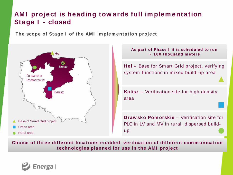
AMI project is heading towards full implementation Stage I - closed
Base of Smart Grid project
Urban area
Rural area
Choice of three different locations enabled verification of different communication technologies planned for use in the AMI project
Hel – Base for Smart Grid project, verifying system functions in mixed build-up area
Kalisz – Verification site for high density area
Drawsko Pomorskie – Verification site for PLC in LV and MV in rural, dispersed build-up
Hel
Kalisz
Drawsko Pomorskie
As part of Phase I it is scheduled to run ~ 100 thousand meters
The scope of Stage I of the AMI implementation project

The program supports Energa Operator in achieving its strategic goals
AMI program objectives
• Remote metering data acquisition
• Remote control of metering devices
• Increase in operational efficiency
• Optimization of grid management and development processes
• Increase of customer awareness in the areas of energy efficiency and distributed generation
• Accordance with regulatory requirements for meter reading
Implementation of AMI system is the first step towards Smart Grid deployment in Energa Operator

AMI system – conceptual schema for Poland
TAN – Technical Area Network HAN – Home Area Network
Key issues for DSO
Telecommunication technologies Interoperability
• Each of telecommunication segments has different characteristics, therefore telecommunication technologies used can differ in different segments
• Telecommunication technology can differ across segment due to local conditions
• Investments required to set up a smart metering system are significant, therefore DSOs should invest in solutions that are not closed to one supplier only
• Choice of an interoperable solution will improve DSOs’ negotiation position with suppliers and therefore it would help DSOs to reduce its future spend required to develop and maintain the system
Interoperability and robust telecommunications are among the key issues to be considered by DSOs

Separation of modules in our system gives us required scalability and makes us independent from suppliers
• Data acquisi-tion
• Data mana-gement
• High speed fiber connections in the corporate computer network
• Used to transfer data to the application
• IP network separated by Ethernet plugs
• Independent on carrier type
• Each MV/LV substation equipped with data concentrator and balancing meter
• Smart Meters • Low voltage PLC network • Data concentrators • Possibility to install meters
and concentrators from different producers in the target model
• Devices installed at customers’ premises
Energa Operator AMI system is split into several modules separated by well-defined interfaces
General design of AMI System in Energa Operator
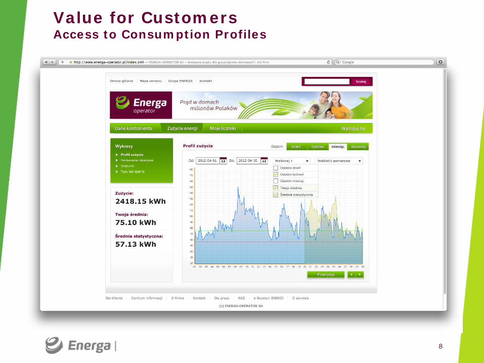
Value for Customers Access to Consumption Profiles
8

9
Value for Customers Selected analysis tools
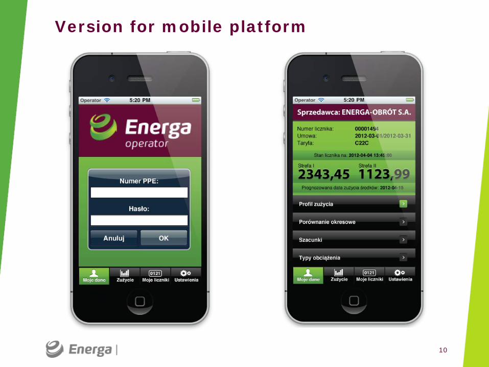
Version for mobile platform
10

Information and communication technology
Development of information and telecommunication technology
Smart DSO
Optimal use and development of resources and assets
Smart network control
Advanced network management and control under conditions of
dynamic growth of distributed generation
Key areas of the development of Smart Grids in Energa-Operator
Active customer
Creating the conditions
for activation of customers within energy generation
and consumption
Quality of supply
Improvement of power supply reliability
and supplied energy quality
1 2 3
5
4
Smart Grid Vision by 2020

Smart grids includes existing and new elements in network infrastucture Smart grid elements
Power lines and substations
• Transmission lines
• HV Substations
• MV/LV substations
• Customers power lines
Telecommunication infrastructure and data exchange
• Teletransmission networks
• Data bases
• Data processing applications
Measurement systems and control devices
Network management and process support systems
• Smart meters
• Network parameters mesurement systems
• Network automation devices
• SCADA systems
• Power outage detection and failure elimination systems
• Asset management systems

Conception
2011 2012 2013
Implementation Research and analysis
• Number of customers – 10 000
• Distribution MV network – 200 km
• Distribution LV network – 150 km
• Substations 15/0,4 kV – 150
Smart Grid Pilot Area Hel Peninsula
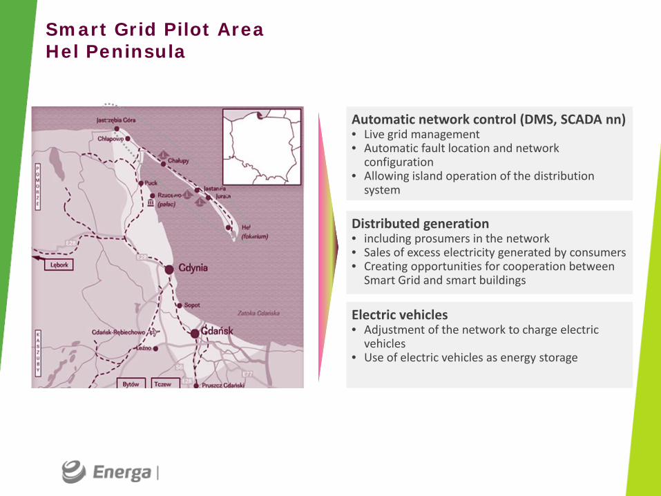
Automatic network control (DMS, SCADA nn) • Live grid management • Automatic fault location and network
configuration • Allowing island operation of the distribution
system
Distributed generation • including prosumers in the network • Sales of excess electricity generated by consumers • Creating opportunities for cooperation between
Smart Grid and smart buildings
Electric vehicles • Adjustment of the network to charge electric
vehicles • Use of electric vehicles as energy storage
Smart Grid Pilot Area Hel Peninsula

Agenda – again … just to reffer to its last point
• AMI roll-out
• Added values for our customers
• Smart Grid laboratory - project located in area of Hel Penisula
• Project „Road Map for Smart Grids implementation till 2020”

Thank you for your attention