Embed Size (px)
Citation preview

223
Cya
nMag
enta
Yello
wBl
ack
The
Cha
in R
eact
ion-
Volu
me
02 (P
art 0
3) #
150
Dt.:
29/1
0/20
05
CyanMagentaYellowBlack
Chapter 5
Enabling Technologies – A bouquet
“Enabling technologies” refers to advanced techniques, processes, instrumentation and systemsdeveloped through synergistic interactions between interdisciplinary community of engineeringprofessionals from industry, scientists & technologists from research organisations and teachers &students from academic institutions. The success of the nuclear fuel cycle depends to a greatextent on the enabling technologies such as non-destructive testing and evaluation, robotics,remote handling and process instrumentation. Non-destructive evaluation (NDE) ensures thesafety and integrity of the nuclear plants and components. Remote handling and robotics is ofparamount importance in fuel handling, post-irradiation examination as well as in-service inspection.
Process instrumentation is the 'eye and ear’ of the nuclear facilities. Reliable sensor devicesand intelligent signal processing instrumentation systems with failure rates less than 10-3/yearneed to be developed for ensuring reliable and safe operation of the nuclear facilities.
Appropriate modelling and development of various codes crucially depend upon the availabilityof large scale computing facilities. Super computing facilities are thus indispensable tools in Research& Development of any scientific organisation and the Department has taken rapid strides in thisdirection.

224
Cya
nMag
enta
Yello
wBl
ack
The
Cha
in R
eact
ion-
Volu
me
02 (P
art 0
3) #
150
Dt.:
29/1
0/20
05
CyanMagentaYellowBlack
"...When nuclear energy has been successfully applied forpower production, in say, a couple of decades from now,India will not have to look abroad for its experts, but willfind them ready at hand..."
- Dr. Homi J. Bhabha

225
Cya
nMag
enta
Yello
wBl
ack
The
Cha
in R
eact
ion-
Volu
me
02 (P
art 0
3) #
150
Dt.:
29/1
0/20
05
CyanMagentaYellowBlack
Non-destructive testing (NDT) is a general name given toall inspection methods, which permit testing of material withoutimpairing its future usefulness. Radiography, ultrasonic, eddycurrent, magnetic particle and liquid penetrant testing are someof the conventional methods, which are widely used by theindustries. By such methods, it is possible to assess theintegrity and quality of materials and their fitness for purpose.Since each NDT method is capable of detecting only certaintypes of defects, it may be necessary to employ more than onemethod for complete and rigorous quality evaluation of material.NDT when applied systematically also reveals the progressivedivergence from a standard of quality. For plants in service,
NDT is an invaluable tool for preventive maintenance as itidentifies faulty components at an early stage. NDT methodsalso provide necessary inputs to determine the residual life ofcomponents in operating plants.
The science and art of NDT is more than 100 years old. Ourancient potters had practiced this to ensure the quality of pots.Master metal craftsmen in our country have used empirical NDTmethods for producing the world’s most cherished and beautifulbronze icons and the famous Damascus Swords.
In the modern industrial world, NDT is used to ensure qualityfrom raw materials stage through fabrication, processing, pre-service and inservice inspection. In short, right from the cradle
Non-Destructive Testing

226
Cya
nMag
enta
Yello
wBl
ack
The
Cha
in R
eact
ion-
Volu
me
02 (P
art 0
3) #
150
Dt.:
29/1
0/20
05
CyanMagentaYellowBlack
to tomb of a component, NDT is being applied. Today, NDT is
indispensable in practically all the industries.
Internationally, since 1920s, NDT has developed from a
laboratory curiosity to an indispensable industrial tool. In the
1950s, awareness about NDT was quite low in India and it was
practised in a minimal way in select organisations. NDT shot
into prominence only after the atomic energy program came
into existence.
Initiation of NDT in Atomic Energy ProgramNuclear fuel being the source of power in the reactor, it is
one of the most critical elements. Ensuring the requisite
properties, dimensional control and meeting the stringent and
exacting specifications is thus of paramount importance.
Realising the need for a programme of non-destructively testing
fuel elements in a rigorous and exhaustive way from the point
of view of safety, performance and efficiency, a small team with
Shri K.Balaramamoorthy was formed under the guidance of
Dr. N.Kondal Rao in 1956 with the specific mission of generating
the required expertise and also ensuring that the first half charge
for CIRUS met the quality specifications. The flow sheet for
production of the fuel elements involved many steps.
It was thus left to the ingenuity of the team to select
appropriate NDT methods and devise the necessary procedures
and techniques. The starting material for the production of
fuel elements for CIRUS was natural uranium in the form of
ingots. The first step in their fabrication was vacuum melting
and casting. After vacuum melting, the required charge was
cast under vacuum into a mould for obtaining a billet of about
3” diameter and 36” length. The billet was to be free from defects
such as blow holes and primary or secondary piping. The best
method for the quality evaluation of cast uranium billet was
ultrasonic method. The first NDT equipment to be inducted in
the Department was thus, an ultrasonic unit from M/s. Kertz,
Poland, in 1957 for the inspection of these billets.
A good quality billet was hot rolled in successive steps to a
rod of about 1.450” diameter and 130” length and the same
was given a beta heat treatment, in order to get random
orientation of the grains, thereby obtaining dimensional stability
during the reactor operation. This uranium rod should meet
the rigid dimensional tolerances specified and it should also be
free from any rolling defects, surface or subsurface quenching
cracks. Ultrasonic methods were not much useful as these are
not sensitive for detection of defects, which lie close to the
surface. It was advantageous to choose a method by which
diameter variations of the object under test as well as defects
(cracks, seams, pitting, etc.) were detected in a single test.
The best answer for these requirements was the eddy current
testing method. Thus in 1958, the first eddy current equipment
from Dr. Foster’s Lab was inducted.
The uranium rod was cleaned and then jacketed and sealed.
It was mandatory that the fuel element should be sealed only
by welding. The criterion of weld quality is not its strength but
its integrity, that is, the ability to keep the coolant outside the
cladding throughout the service of the fuel element. As the
cross-section of the weld was small, the defects to be detected
were much smaller than the cross-section of the element and
actually no lower limit for acceptability could be placed on the
size of a defect. Defects simply must not exist. No single test
was found to be adequate. A combination of two methods,
radiography and leak testing using glycol was found to be the
best solution. In 1958, the first X-ray unit was installed in Project
Faggots. Incidentally, this unit is still working (after 47 years)
and is being used for various NDT applications. Leak testing
was the final crucial NDT for the fuel element. The apparatus
for leak testing was indigenously setup and the fuel elements
tested with it. By the end of 1959, all the fuel elements for
CIRUS were fabricated and tested. Two of the elements were
also sent to Canada for testing and checking their performance
in the Canadian reactor Chalk River Facility. Both these
elements performed exceedingly well. It was indeed a feather
in the cap of DAE to have accomplished this feat in the face of
some diffidence in the minds of Canadian counterparts.
During the 1960’s BARC had taken up the design of a
prototype power reactor – a natural uranium oxide heavy water
By 1959 all the conventional NDT methods had beenestablished and used at the Project Faggots of AtomicEnergy Establishment, Trombay (AEET).
AEET became the first unique establishment in the countryto have all the NDT techniques established under a singleroof and with relevant technical expertise.

227
Cya
nMag
enta
Yello
wBl
ack
The
Cha
in R
eact
ion-
Volu
me
02 (P
art 0
3) #
150
Dt.:
29/1
0/20
05
CyanMagentaYellowBlack
moderated, pressurised heavy water cooled system. This was
the next stage of collaboration between India and Canada and
it was again decided that half the initial requirement of the fuel
bundles (~1800 in number) would be made by India. This task
was successfully completed. Both these events were major
milestones in the history of atomic energy program in the country
in assuring high standards of quality in fuel fabrication through
appropriate and judicious choice of NDT.
Over these 40 years, Atomic Fuels Division (AFD) of BARC
has become a pioneer in the field of fabrication of metallic fuel
and related sub-assemblies. It has so far supplied about 6000
fuel elements to CIRUS and around 3500 fuel clusters to
Dhruva. It has made significant changes in the production tech-
niques not only to enhance the production rate but more im-
portantly also to enhance quality of the fuel being produced. In
the seventies and eighties, this division played a crucial role in
producing fuel clusters of different designs to carry out the ini-
tial design verification trials and thus significantly helped engi-
neers to reach the most optimum design of fuel and core com-
ponents for Dhruva. One of the other major achievements was
the technology development of control blades of TAPS. Dur-
ing late 1970s, it was being felt by TAPS authorities that in a
few years time, M/s General Electric, USA might stop the sup-
ply of control blades, which was essential for operation of the
reactor. Considerable amount of technology development work
was involved which included development of manufacturing
drawings, using NDT techniques to generate component and
assembly dimensions with precise tolerances, material selec-
tion and grade for each component (Total : 24 components),
B4C powder development and vibro compaction techniques to
achieve required density, welding development and its qualifi-
cations, various QA and QC plans, etc. After extensive proto-
type testing during 1977 to 1983, DAE safety review commit-
tee cleared the control blades nos. 1 & 2 for loading in TAPS in
1983. The first two blades performed exceedingly well in the
reactor and lasted their full operation of around seven years.
Since then, AFD has been continuously fabricating and sup-
plying control blades to TAPS. Till today around 80 blades have
been supplied and they all have performed well in the reactor.
While AFD, BARC took care of the requirements of PHWRs,
to cater to the NDE requirements of the Fast Reactor program,
a NDT facility was initiated and set up at IGCAR (then Reactor
Research Centre) in the late 1970s. In a short span of ten
years all the conventional and advanced NDT facilities were
established and this facility – Division for PIE & NDT Develop-
ment (DPEND) became the Centre for Excellence in NDT
known nationally and internationally. Many of the NDT activi-
ties especially in the area of advanced NDT techniques were
pioneered from here. DPEND also took the lead in develop-
ment of NDT methods and techniques for pre-service inspec-
tion (PSI) and in-service inspection (ISI) of PFBR components
such as steam generator, main vessel and safety vessel.
NDT in Fuel Fabrication (Power Reactors)With the commissioning of the Tarapur Atomic Power Station
in 1969, greater thrust was given to the first stage of nuclear
power program i.e. design and development of Pressurised
Heavy Water Reactors. To cater to the requirement of natural
and enriched uranium oxide fuels for the PHWRs and BWRs
and for industrial scale manufacture of nuclear fuel
subassemblies and zircaloy structural components for power
reactors, the Nuclear Fuel Complex (NFC) was setup at
Hyderabad in 1971, based on the R&D activities at BARC during
the 1960s.
Right from the inception of NFC, a great emphasis has been
placed on quality. Initially the philosophy was quality control
with predominantly multicentered testing and inspection. Later,
with the diversification of production programme, a
comprehensive Quality Assurance programme which would
assure the reliability of the process and ensure the quality of
the products was put in place. A variety of techniques were
employed to ensure conformance to specifications and to assure
quality at each manufacturing stage.
While initially the major conventional NDT techniques were
established, over the years the capability for NDT has been
enhanced several fold by the addition of specialised equipments
The modern concept of QUALITY is “total customersatisfaction”. However, even before this evolved, DAE hadadopted this concept through the philosophy of ‘do It rightfirst time, in time, and every time’. This was also the key forcompetitiveness and cost effectiveness.

228
Cya
nMag
enta
Yello
wBl
ack
The
Cha
in R
eact
ion-
Volu
me
02 (P
art 0
3) #
150
Dt.:
29/1
0/20
05
CyanMagentaYellowBlack
such as high definition boroscopes for internal surface
examination of pressure tubes and other zircaloy tubes
designed with close tolerances and real time x-ray radioscopy
for examination of critical welds of nuclear components. For
continuous flaw detection and wall thickness measurement on
100% basis, several semi-automatic and automatic UT stations
were installed on the shop floor. Specifically, for coolant tubes
which have to remain in the reactor for many years, a micro-
processor operated high-speed tube rotation UT system fitted
with line/spot focus transducers is employed for covering entire
surface including detection of laminations. Further, a
computerized and fully automatic UT system based on probe
rotation has been installed for testing of flaws and wall thickness
of fuel tubes, using control chart method for calibration. Eddy
current testing is regularly employed for surface and sub-surface
defects in Zr-2.5% Nb coolant tubes and is also used for
identification of zirconium alloy intermediates and scrap.
Penetrant testing is mandatory for locating cracks and porosities
in the seam-welded zircaloy tubes and also zirconium alloy rods,
plates and sharp ends of garter springs. Helium leak testing
has emerged as a highly sensitive and reliable technique for
qualifying weld integrity of the fuel elements and bundles. The
presently allowable leak rate is less than 1 x 10⁻⁸ std cc/sec. To
ensure that this stringent standard is met, a multi-stage testing
procedure has been evolved with fuel elements pre-pressurised
with helium gas prior to end cap welding and subsequently
bombing with helium, for back filling before leak testing.
One of the major achievements of NFC over the years has
been the indigenisation of most of the machineries and
equipment. Most of the quality control equipment in the three
new plants engaged in PHWR fuel fabrication, namely, the New
Uranium Oxide Fuel Plant (NUOFP), the New Zirconium
Fabrication Plant (NZFP) and the New Uranium Fuel Assembly
Plant (NUFAP), have been manufactured by Indian firms, based
on NFC’s design and guidance.
NDT for In-Service Inspection in Reactors and HeavyWater Plants
A major concern in nuclear power plants is that of accidental
release of radioactivity and radioactive products. Therefore,
all those components that could cause unacceptable release
of radioactivity, have to be in acceptable condition of health.
Hence periodic in-service inspection (ISI) of such components
is mandatory. Periodic ISI serves two objectives:
It provides an assurance that the components are quite
healthy and there is no danger to the health and safety of
the personnel, plant and public. This is particularly essential
in case of nuclear core components, which are subjected to
additional factors such as fast neutron fluence, high
temperature and radiation (X-ray and gamma-ray) all of
which degrade material properties. Thus, periodic inspection
of components is mandatory to assure that even the
degraded materials are adequate to take the stress and strain
throughout the remaining life of the plant.
ISI provides valuable baseline data, which when coupled
with analytical modelling using computer codes helps in
estimating residual life as part of the ageing management
program.
The necessity for in-service assessment of integrity of
components in operating nuclear power plants was recognised
internationally in the mid sixties. In 1969, IAEA published
“Guide to periodic inspection of nuclear reactor steel pressure
vessels”. This document mainly concentrated on light water
reactors. For PHWR type reactors it was the Canadian
standards Association, which brought out the document
“Periodic Inspection of CANDU Nuclear Power Plant
supplementary inspection." In 1980, IAEA published the IAEA
Safety Guide: 50-SG-02 “In-Service Inspection for nuclear
power plants” which covered requirements for heavy-water-
cooled pressure tube reactor and other reactor plants. In India,
Atomic Energy Regulatory Board (AERB) published the code
for practices on “Safety in nuclear power plant operation” and
“Safety in nuclear power plant design”. These codes covered
ISI in a very broad sense.
One of the earliest NDE techniques used for ISI in RAPS-1
was eddy current testing to locate the leaky tubes in heat
exchangers. This was in 1978. Since then, a number of
inspection related developments have been successfully
undertaken to meet specific demands from the operating plants.
One of the most critical components in the entire primary heat
transport system of PHWR is the pressure tube of coolant
229
Cya
nMag
enta
Yello
wBl
ack
The
Cha
in R
eact
ion-
Volu
me
02 (P
art 0
3) #
150
Dt.:
29/1
0/20
05
CyanMagentaYellowBlack
channel since its design margin is kept to a minimum from
neutron economy consideration. Fabricated from zirconium
alloy, these tubes are susceptible to radiation induced
dimensional changes and hydriding. ISI is therefore necessary
to confirm their structural integrity and to collect data related to
long-term performance of the material. This data is necessary
to establish additional inspection and maintenance
requirements, to predict residual life of coolant channels and to
initiate action on replacement if required. The data thus
collected is also of vital importance for design of coolant
channels in future reactors.
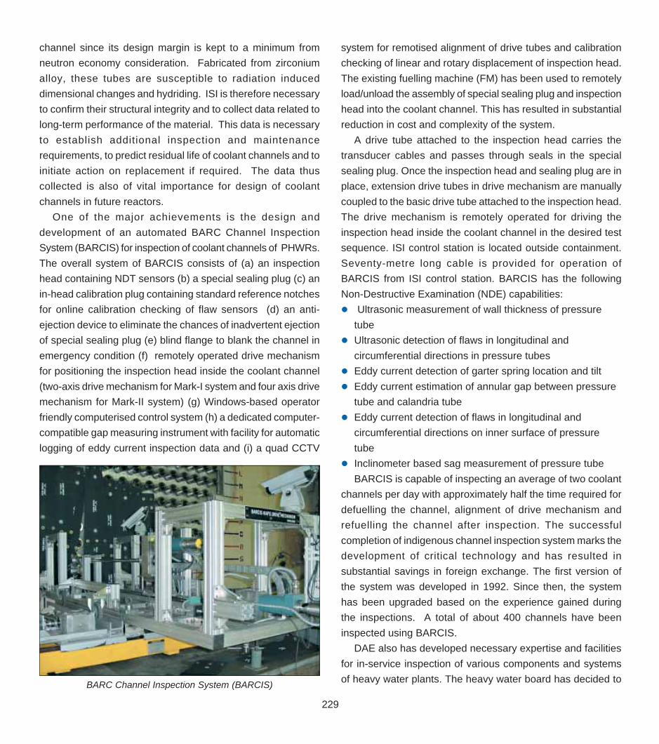
One of the major achievements is the design and
development of an automated BARC Channel Inspection
System (BARCIS) for inspection of coolant channels of PHWRs.
The overall system of BARCIS consists of (a) an inspection
head containing NDT sensors (b) a special sealing plug (c) an
in-head calibration plug containing standard reference notches
for online calibration checking of flaw sensors (d) an anti-
ejection device to eliminate the chances of inadvertent ejection
of special sealing plug (e) blind flange to blank the channel in
emergency condition (f) remotely operated drive mechanism
for positioning the inspection head inside the coolant channel
(two-axis drive mechanism for Mark-I system and four axis drive
mechanism for Mark-II system) (g) Windows-based operator
friendly computerised control system (h) a dedicated computer-
compatible gap measuring instrument with facility for automatic
logging of eddy current inspection data and (i) a quad CCTV
system for remotised alignment of drive tubes and calibration
checking of linear and rotary displacement of inspection head.
The existing fuelling machine (FM) has been used to remotely
load/unload the assembly of special sealing plug and inspection
head into the coolant channel. This has resulted in substantial
reduction in cost and complexity of the system.
A drive tube attached to the inspection head carries the
transducer cables and passes through seals in the special
sealing plug. Once the inspection head and sealing plug are in
place, extension drive tubes in drive mechanism are manually
coupled to the basic drive tube attached to the inspection head.
The drive mechanism is remotely operated for driving the
inspection head inside the coolant channel in the desired test
sequence. ISI control station is located outside containment.
Seventy-metre long cable is provided for operation of
BARCIS from ISI control station. BARCIS has the following
Non-Destructive Examination (NDE) capabilities:
Ultrasonic measurement of wall thickness of pressure
tube
Ultrasonic detection of flaws in longitudinal and
circumferential directions in pressure tubes
Eddy current detection of garter spring location and tilt
Eddy current estimation of annular gap between pressure
tube and calandria tube
Eddy current detection of flaws in longitudinal and
circumferential directions on inner surface of pressure
tube
Inclinometer based sag measurement of pressure tube
BARCIS is capable of inspecting an average of two coolant
channels per day with approximately half the time required for
defuelling the channel, alignment of drive mechanism and
refuelling the channel after inspection. The successful
completion of indigenous channel inspection system marks the
development of critical technology and has resulted in
substantial savings in foreign exchange. The first version of
the system was developed in 1992. Since then, the system
has been upgraded based on the experience gained during
the inspections. A total of about 400 channels have been
inspected using BARCIS.
DAE also has developed necessary expertise and facilities
for in-service inspection of various components and systems
of heavy water plants. The heavy water board has decided toBARC Channel Inspection System (BARCIS)

230
Cya
nMag
enta
Yello
wBl
ack
The
Cha
in R
eact
ion-
Volu
me
02 (P
art 0
3) #
150
Dt.:
29/1
0/20
05
CyanMagentaYellowBlack
assess the integrity of selected plant components, which had
experienced most aggressive conditions, as a benchmark for
qualification of all the other components. As part of this
programme, Acoustic Emission (AE) monitoring during hydro-
pneumatic testing of a waste heat stripper, that operates under
the most severe conditions has been successfully carried out.
An ultrasonic test procedure for assessment of hydrogen
damage in one of the conical inlets of the heavy water plants
and also for requalification of the rehabilitated conical inlet was
successfully developed and implemented. The alternate solution
- replacement by imported component would have resulted in
long shut down of the plant.
Economics of nuclear power generation demands highest
priority to be placed on the uninterrupted availability of plant.
This implies that preventive maintenance is a necessity for the
successful operation of nuclear power plant. A number of NDE
methodologies for predictive condition management of
components have been developed to meet this requirement.
Thermography or thermal imaging, an advanced NDE method,
based on the detection of infrared radiation was successfully
used for condition monitoring of components and electrical
installations in PHWRs. Early detection of abnormalities was
demonstrated at TAPS and MAPS for undertaking preventive
maintenance, thus avoiding costly outages. Some of the
components inspected include transformers bushing regions,
wall mounted insulators and switchyard components. Minor hot
spots detected in the carbon brushes of a generator
demonstrate the sensitivity of the thermal imaging.
Heavy Water Plant in Tuticorin employs the ammonia-
hydrogen exchange process (mono thermal), in which enriched
ammonia is cracked to produce heavy water. Cracking of
ammonia (endothermic reaction) is carried out at a pressure of
135 kg/cm2 and at a temperature of 873 K when the ammonia
is allowed to pass through 70 Inconel-625 tubes filled with iron
catalyst. The tubes have an external surface temperature of
the order of 800 – 990 K. The flames that burn in this furnace
can achieve temperatures as high as 1350 K. It is important
that these tubes operate at their designed optimum operating
temperature and do not exceed the maximum limit of 993 K.
Operation of the tubes at higher temperatures for a sustained
period of time reduces the life of the tube, which can result in
loss of ductility and creep damage leading to premature and
catastrophic failure. In case the tubes are operated at lower
than their optimum temperatures, there would be incomplete
cracking of ammonia resulting in lower yield. Thus, periodic
monitoring of the skin temperature distribution of the catalyst
tubes at regular intervals is recommended to ensure optimum
yield of the product, safety of the operation and long life for the
tubes, thus ensuring smooth and safe functioning of the plant.
Thermal imaging has been successfully used to comprehe-
nsively assess skin temperatures of these tubes. Thermal
Infrared thermal images reveal useful information of the nuclearcomponents. Shown here is the thermal image of the slip rings at
MAPS. Slip rings carry main excitation current of ~1000 amperes tothe rotors. Higher the temperature, higher is the wear rate of
carbon brushes. A few hot spots are noticed which are well withinprescribed limits
Typical thermal image of the cracker tubes in a heavy water plant.This thermal image reveals (1) - Flames impinging directly on thetubes (indicated by arrow). Skin temperatures of the tubes in such
cases can be seen to exceed the prescribed limit of 993 K. (2)-Reflections from metal used for fastening the thermocouple
(appearing like hot area) (3)- Flames in the background

231
Cya
nMag
enta
Yello
wBl
ack
The
Cha
in R
eact
ion-
Volu
me
02 (P
art 0
3) #
150
Dt.:
29/1
0/20
05
CyanMagentaYellowBlack
NDE Equipment/ Facilities PIE application
Scanning wall periscope, Visual examination
magnifying glass, CCD camera of fuel subassemblies,
fuel pins, coolant
channel components.
Stepper motor controlled bench Profilometry of fuel pins
with LVDTs, digital micrometer for (OD and ID
linear and three point micrometer measurements)
Gamma scanning Fission product distri-
bution. Burnup estimation,
Inhomogenities in fuel.
X-radiography Pellet to Pellet gap,
stack length of fuel
Neutron radiography Pellet inhomogenities,
fuel density variations
in fuel pins , hydriding
in coolant channel
component
Eddy Current Detection of clad
surface defects, oxide
layer measurement in
coolant channel
components.
Ultrasonic testing End cap weld examin-
ation, failed fuel pin
detection ( at pool side)
Alpha, Beta and gamma Autoradiography of fuel
Autoradiography cross-sections,
determination of
segregations.
Remote Metallography Microstructure of fuel,
fuel cracking, fuel clad
gap, clad carburisation,
fuel restructuring.
imaging also provided the thermal gradient along the tubes as
a function of position, which helped the plant personnel to
regulate the temperatures. Apart from catalyst tubes, thermal
imaging helped in identifying areas of energy losses (due to
lack of insulation/ deteriorating insulation, etc.) in pigtails,
furnace walls, etc.
NDE for PIE ApplicationsPost-irradiation examination (PIE) is an essential link in the
nuclear fuel cycle. PIE provides valuable information to the fuel
designers, fabricators and reactor operators on the performance
of fuel and structural components. This feedback information
is vital in determining the residual life of fuel and incore structural
material and also helps in improving the safety, reliability and
economics of nuclear power generation. A host of conventional
and advanced NDE methods have been successfully utilised
for the PIE of BWR, PHWR and FBTR fuel and structural
materials.
Application of NDE methods for PIE has provided valuable
insight into the irradiation behaviour of the materials. Data from
application of various NDE methods in conjunction with other
test data have provided confidence (a) to the reactor personnel
to enhance the burnup and linear heat rating of the fuel and (b)
to the designers to take more challenging tasks for PIE of PFBR
fuel and structural materials.
Periscope for FBTRPeriscope is an optical device meant for detailed visual
inspection of components/structures in areas where direct
observation is not possible like internals or hot-cell equipments
of nuclear reactors. Though many sensor based systems are
available to monitor operating parameters such as temperature,
pressure etc., periodic visual inspection of critical components
is necessary and mandatory to assess health of the components
as well as to detect surface damages, blocks etc. The reactor
internals or components in a hot-cell can be seen using
instruments and accessories such as camera, fibre optic
devices. But to see the fine details such as cracks, surface
defects etc. use of periscopes is necessary. These devices have
to be specially designed to enable their working in harsh
environments like high temperatures of the order of 150 oC

232
Cya
nMag
enta
Yello
wBl
ack
The
Cha
in R
eact
ion-
Volu
me
02 (P
art 0
3) #
150
Dt.:
29/1
0/20
05
CyanMagentaYellowBlack
coupled with presence of sodium aerosols and nuclear radiation.
The design should be also amenable to their safe and easy
introduction/retrieval into the reactor containment primary
boundary using existing service penetrations without loss of
leak tightness.
The first periscope was installed in FBTR in 1985. It took
about 4 to 5 years to develop, as there was only one
manufacturer of optical components. Special optical design
was made by Spectroscopy Division, BARC. Centre for Design
and Manufacture (Formerly Central Workshops), BARC did the
kinematics design as well as detailing and later took up
manufacture of components of assembly. This instrument
proved to be highly useful. It was used for over 10 years and
later it was felt necessary to have another periscope with
improved design and additional features based on the feedback
from use of the Mark I equipment. A new periscope (Mark II)
was successfully produced in 2004. This new periscope has
enhanced coverage, zooming, and improved contrast. A new
illuminator using 400 watt Xenon lamp, condenser lens and a
mirror reflector to direct the light to desired spot as well as
provision for Argon cooling are also added. The reflector of this
illuminator is gold coated for longer life.
The experience gained in the development of such
specialised and custom built equipment has given the impetus
for embarking upon design and development of a much bigger
periscope for inspection of FBR internals. This periscope will
have advanced design features and facilities for examination
of the fuel sub-assembly heads in the sodium drained condition.
In-house development of NDE InstrumentationNDE instrumentation is an interdisciplinary area of pursuit.
The aim of this programme is to develop systems based on
NDE sensors required at various stages right from material
selection, fabrication, heat treatment, pre-service inspection to
in-service inspection (ISI). Realising the importance of this
programme, the Department has laid great emphasis on building
up excellent expertise and facilities in conventional and
advanced NDE techniques.
One of the successes is the development of ultrasonic
imaging systems for non destructive testing of materials (the
so called B & C Scan system). The first such system was
developed in the early nineties. Initially, this system was of
stand-alone nature and it was interfaced to the personal
computer (PC) via the printer port. As the PCs became faster,
more powerful and their costs declined, PC based versions of
such systems were developed and supplied on a commercial
basis. These systems were extensively used for the inspection
of a variety of mechanical assembly parts including feed water
nozzle (at TAPS) and Gas turbine rotors (at BHEL). High Speed
Digitizer is the heart of such systems. High sampling speed
permits use of high frequency transducers, which are mandatory
for high-resolution NDE inspections. Special efforts were put
in for developing high-speed digitizers suitable for ultrasonic
imaging systems as well as other scientific/engineering
applications needing capture and analysis of high frequency/
high-speed signals. Constant innovation has always been the
main driving force in all the developments in DAE. In tune with
this, hardware / software up-gradations were incorporated from
time to time in both the high speed digitizer as well as the
ultrasonic imaging systems developed over last 15 years or
so. During 1999, a generic name ‘ULTIMA’ was assigned to
Ultrasonic Imaging Systems developed at Electronics Division,
BARC. The sampling speed was added as a suffix. Thus,
Photograph showing the ULTIMA 100M2 2- Channel UltrasonicImaging System

233
Cya
nMag
enta
Yello
wBl
ack
The
Cha
in R
eact
ion-
Volu
me
02 (P
art 0
3) #
150
Dt.:
29/1
0/20
05
CyanMagentaYellowBlack
ULTIMA 100 implies an Ultrasonic Imaging Systems with a 100
Million Samples per Second (MSPS) Digitizer.
A review of these developments reveals that the hardware
developments have evolved from stand alone ISA bus based
systems to PCI bus based systems. The software evolution
has taken place from DOS based to Windows 95 and then to
Windows based Lab View platforms. Both single channel and
multi-channel systems have been developed. The systems
are being successfully used for material characterisation studies
and applications such as inspection of solid forgings (190 mm
diameter 2500 mm length, with a weight of 700 kg each), which
are used for machining end fittings for coolant channels of
500 MWe PHWRs.
As a part of the research programme undertaken on
development of NDE techniques and systems for
comprehensive evaluation of microstructures and damage, a
Magnetic Barkhausen Emission (MBE) system was developed
at IGCAR. The system along with the probes developed was
used for a variety of studies including assessment of
microstructural variations due to thermal ageing, tensile
deformation, creep and fatigue damage, induction hardening
depth and carburisation depth. Different zones in ferrite steel
weldments i.e., base metal, weld metal, heat affected zone
(coarse gained bainite /martensite, fine grained bainite/
martensite and intercrticial region) could be effectively identified.
Studies have also been made for assessment of adequacy of
post-weld heat treatment in the case of trial tube to tube weld
of steam generator of prototype fast breeder reactor.
Conventional eddy current testing technique cannot be
applied for the in-service inspection of ferromagnetic tubes of
SG, due to continuously varying permeability, which leads to
poor signal to noise ratio and consequent reduction in defect
detection sensitivity. In view of this, a first-of-its- kind Remote
Field Eddy Current (RFEC) system with probes and complete
instrumentation was developed. The probe design was
optimized with the help of a 2D axi-symmetric finite element
model developed in-house. The probe is made flexible for easy
negotiation in the bend regions of the SG tubes of 23 m long.
High density tungsten carbide or depleted uranium rings are
used in the flexible probes for easy sliding of the probe by
gravity. Advanced signal processing methods based on wavelet
transforms have been developed for elimination of large
amplitude interference signals from bend regions and also
sodium deposits if any, on the inside surface of the tube. The
RFEC technique developed is capable of detecting indications
equivalent to uniform wall thinning of 10%. It was successfully
used for the detection of defects in monel tubes having non-
uniform crud deposits on the tube outer surface.
Acoustic emission (AE) testing procedures, capable of
detecting dynamic events, were also successfully developed
and implemented for detection of leaks in end shield, pressure
tubes and seal plugs in coolant channels. A PC-based multi
channel AE system was designed and developed indigenously.
The system can handle basic AE parameters such as count
rate, cumulative count, event rate, cumulative events, event
duration, counts / event, RMS value, peak value and rise time.
It also accepts four conditioned external parameters like load,
strain, temperature and pressure. The system has been
configured on dual PCs, one dedicated for data acquisition and
the other for data presentation and analysis, thus increasing
the throughput of the system. It is capable of handling more
than 6 thousand bits/s of AE signal. The system is simple, field
worthy and cost effective and has been validated with
international systems.
Apart from the above, a variety of NDE probes and sensors
were indigenously developed depending on the need of the
hour. Typical sensors include focused differential surface eddy
current sensor for detection of scratch marks in calandria tubes.
Such scratch marks could be formed during the removal of
B-scan image of pressure tube with hydride blister using normalbeam longitudinal wave technique
234
Cya
nMag
enta
Yello
wBl
ack
The
Cha
in R
eact
ion-
Volu
me
02 (P
art 0
3) #
150
Dt.:
29/1
0/20
05
CyanMagentaYellowBlack
pressure tubes as part of en-mass coolant channel replacement
programme. The sensors could detect scratches more than
25 µm deep. Using the probes and the procedures developed,
calandria tubes were successfully inspected both at RAPS-2
and MAPS-2.
Research and DevelopmentAn important R&D programme of DAE is related to
development of procedures for comprehensive evaluation of
defects, microstructures, residual stresses and damage in
various nuclear materials with high sensitivity and reliability, by
using judiciously selected complementary NDE techniques.
3-D imaging of the interior of an object has been one of the
important goals of NDT and it has many industrial and strate-
gic applications. It can be used for reverse engineering and for
examination of defects and cracks in their full three dimensional
perspective. A 3-D cone beam tomography system was devel-
oped at BARC using cooled CCD and GdOS(Tb) scintillator.
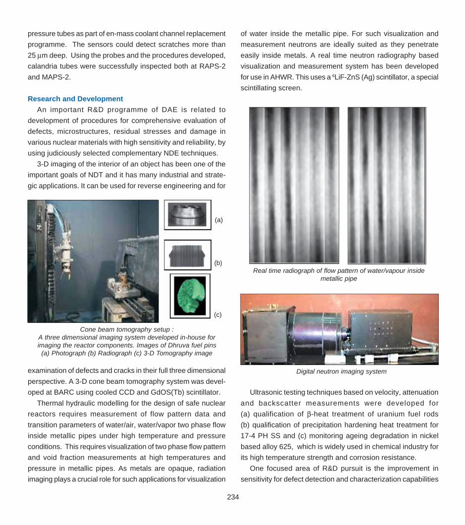
Thermal hydraulic modelling for the design of safe nuclear
reactors requires measurement of flow pattern data and
transition parameters of water/air, water/vapor two phase flow
inside metallic pipes under high temperature and pressure
conditions. This requires visualization of two phase flow pattern
and void fraction measurements at high temperatures and
pressure in metallic pipes. As metals are opaque, radiation
imaging plays a crucial role for such applications for visualization
of water inside the metallic pipe. For such visualization and
measurement neutrons are ideally suited as they penetrate
easily inside metals. A real time neutron radiography based
visualization and measurement system has been developed
for use in AHWR. This uses a 6LiF-ZnS (Ag) scintillator, a special
scintillating screen.
Cone beam tomography setup :A three dimensional imaging system developed in-house forimaging the reactor components. Images of Dhruva fuel pins
(a) Photograph (b) Radiograph (c) 3-D Tomography image
(a)
(b)
(c)
Real time radiograph of flow pattern of water/vapour insidemetallic pipe
Digital neutron imaging system
Ultrasonic testing techniques based on velocity, attenuation
and backscatter measurements were developed for
(a) qualification of β-heat treatment of uranium fuel rods
(b) qualification of precipitation hardening heat treatment for
17-4 PH SS and (c) monitoring ageing degradation in nickel
based alloy 625, which is widely used in chemical industry for
its high temperature strength and corrosion resistance.
One focused area of R&D pursuit is the improvement in
sensitivity for defect detection and characterization capabilities

235
Cya
nMag
enta
Yello
wBl
ack
The
Cha
in R
eact
ion-
Volu
me
02 (P
art 0
3) #
150
Dt.:
29/1
0/20
05
CyanMagentaYellowBlack
by using ultrasonic testing methodologies, for thick austenitic
stainless steel weldments. This is difficult because of large grain
scatter, coarse grain and dendritic structure associated texture
in welds. In order to enhance the sensitivity and reliability of
defect detection and characterization, model-based approaches
including ray tracing and beam skewing considerations and
advanced signal processing methods were developed and
adopted. The present code based specification of detection of
10% wall thickness defects in austenitic welds was improved
by using advanced ultrasonic signal processing methods. The
improved sensitivity was achieved by adopting two new cluster
formation (and analysis) methods and one pattern recognition
method. The cluster analysis methods are (a) scalar mean peak
power (SMPP) method and (b) normalised mean deviation
vector (NMDV) method. The developed pattern recognition
method is called the (c) demodulated autocorrelation function
(DMAC) method. These have been applied to a wide variety of
testing situations for detecting and classifying signals in noisy
environment. These advanced methods have capabilities for
detection of defects of 2% wall thickness size.
Neural network methods are the most preferred for solving
inverse problems in NDE, especially non-parametric regression
problems. A number of Artificial Neural Network (ANN) based
approaches were developed for ultrasonic and eddy current
NDE for (a) defect evaluation in presence of varying surface
roughness in the case of ultrasonic testing, (b) detection and
quantitative characterization of artificial and natural defects of
different shapes and sizes in stainless steels using eddy current
signals and (c) detection of defects in welds in the presence of
disturbing variables such as surface roughness and magnetic
phase.
Conventional ultrasonic testing method suffers from various
limitations, specifically for stainless steel welds and claddings.
These limitations include dependence on operator skill, poor
signal to noise ratio (SNR), uncertainty in accurate defect sizing
due to beam spread, limitations of focused probe and limitations
of large apertures. In order to overcome some of these
limitations, two advanced techniques viz. Time of Flight
Diffraction (TOFD) and Synthetic Aperture Focusing Technique
(SAFT) based ultrasonic inspection methodologies were
established for defect imaging and accurate characterization
in thick welds and claddings, in collaboration with Bharat Heavy
Electricals Limited, Tiruchirapalli. The complementary nature
of these two techniques, specifically with respect to sizing
accuracy and sensitivity for near surface defects from the
scanning surface has been brought out.
Various NDE methodologies have been developed for
characterisation of microstructure and mechanical properties.
Some of the methodologies developed include: identification
of various critical temperatures in ferritic steels using ultrasonic
measurements, ultrasonic based imaging of ferritic steel
weldments and assessment of post-weld heat treatments,
characterization of heat affected zones and PWHT in ferritic
steel weldments using Magnetic Barkhausen Emission (MBE),
assessment of different stages of fatigue damage in ferritic
steels using MBE and X-ray Diffraction (XRD), assessment of
thermal ageing and creep damage in ferritic steels using
ultrasonic velocity and MBE measurements, a new ultrasonic
spectral approach for grain size measurements in ferritic and
austenitic steels, ultrasonic velocity measurements for
monitoring the degree of recrystallization in stainless steel,
ultrasonic and XRD based methodologies for assessment of
in-service degradation and qualification of rejuvenation heat
treatment of service exposed. Inconel 625 used as ammonia
cracker tube in heavy water plants, and a new methodology for
measurement of thickness of NiAl coating on Inconel 718
substrate. Most of the above mentioned methodologies are first-
of-its-kind studies in the world. These studies have considerably
expanded the capabilities for the NDE techniques as material
science tools for comprehensive characterization of
microstructures down to a few nanometer levels.
Support to Strategic and Core SectorsOne of the earliest and interesting problems posed to DAE
in the 1960s was the appearance of hundreds of blisters on
empty Burshane gas cylinders manufactured by the then
Gannon and Dunkerley Company. UT examination clearly
revealed the presence of laminations and gas pockets in the
imported sheets used for making these cylinders. UT as a
quality control check and acceptance was subsequently evolved
and the problem fully solved. A similar challenging case was
the checking of the deck plates and shaft of INS Vikrant. Since
the 1960s, conscious of meeting the national demands, DAE
has extended its expertise and facilities for solving many

236
Cya
nMag
enta
Yello
wBl
ack
The
Cha
in R
eact
ion-
Volu
me
02 (P
art 0
3) #
150
Dt.:
29/1
0/20
05
CyanMagentaYellowBlack
challenging inspection related problems for strategic and core
sectors. Some of the recent important contributions made to
the strategic and core sectors include
Quantitative characterisation of defects in rocket motorcasings, earth sensors of satellites and Titanium tanks andgas bottles used in launch vehicles and satellites
Development of NDE methodologies and procedures for lifeextension of tail rotor blades of helicopters and life extensionof defence fighter and transport aircrafts.
Neutron radiography of pyro-devices used in the launchvehicles such as Polar Satellite Launch Vehicle and geostationary launch vehicle and in satellites. This is acollaborative program between the Department of Space(VSSC) and Atomic Energy. More than 2000 pyro-deviceshave been qualified under this program.
Integrity assessment using acoustic emission monitoringduring hydro testing of a 17 m LPG Horton sphere for BPCL,Mumbai, carried out in collaboration with NationalMetallurgical Laboratory, Jamshedpur, revealing the benignnature of a natural defect present in a weld, thusrecommending its continued use.
Integrity assessment using advanced ultrasonic and on-lineAE monitoring of a carbon dioxide absorber vessel, in anammonia plant of GSFC, Vadodara, in collaboration with IISc,Bangalore and DRDO.
Acoustic emission monitoring during hydro testing of motorcasings for DRDO, as part of qualification of their structuralintegrity.
Development of ultrasonic and radiographic testprocedures for evaluation of defects in electron beam weldedTi alloy power take off shafts used in light combat aircraftsof DRDO.
Apart from rendering support to industries, one of the most
important contributions of DAE to societal development has
been human resource development. In the late 1950s and early
1960s when many were not aware of the dangers of exposure
to radiation, it was BARC which pioneered the training and cer-
tification schemes in the field of industrial radiography. Slowly,
this expertise was extended to all the other techniques as well.
DAE also played a lead role in the formulation of the training
and certification programs by the international Atomic Energy
Agency. Experts from DAE organised and participated in vari-
ous training and certification programs conducted by IAEA in
various countries. In India, DAE was primarily responsible for
the formulation of the first training and certification standard by
the Bureau of Indian Standards. DAE continues its pioneering
role in this area. Experts from DAE play a active role in the
NDT sectional committees in the identification and formulation
of NDT standards for various NDT methods.
Today DAE is a centre for excellence in NDE. NDE has not
only fulfilled the objectives of the nuclear programme but also
contributed to societal development through applications in core
and strategic sectors as well as for human resource
development.
Remote Handling and RoboticsEnabling technologies such as robotics, automation and
remote handling play a crucial role in almost all facets of nuclear
fuel cycle. There is a clear difference between remote handling
and robotics. Remote handling is defined as “handling of tools
or components by an equipment where control is at a distance”,
whereas, robotics refers to the study and use of robots. The
Robotics Industries Association defines a Robot as a
“reprogrammable multifunctional manipulator” designed to move
materials, parts and tools or other specialised devices through
variable programmed motions for a variety of tasks.
In the nuclear field, the need for remote handling and robotics
arises due to the presence of radioactive materials and
hazardous environments. Apart from their ability for use in
confined spaces or locations with limited accessibility, the prime
advantage of using remote handling tools and robotics in the
nuclear industry is that they minimize the exposure of human
beings to radiations thus ensuring safety of personnel.
Remote HandlingThe demands of the nuclear industry were the primary driving
force for the evolution of remote handling tools in India. It was

237
Cya
nMag
enta
Yello
wBl
ack
The
Cha
in R
eact
ion-
Volu
me
02 (P
art 0
3) #
150
Dt.:
29/1
0/20
05
CyanMagentaYellowBlack
DAE that had pioneered production and use of isotopic sources
for radiography applications in the country. In the 1960’s, the
gamma cameras were primarily shielded units in which the
sources were located. Remote handling tools such as CV-Tongs
and Standard Tongs with sphere units were the main remote
tools used to remove the isotopic sources from their shielded
enclosures for radiographic exposure. The activity of these
sources were of the order of a few curies only. When an
ambitious target for nuclear power generation and development
of research reactors for the production of radioisotopes was
set, it became clear that the associated facilities such as spent
fuel handling and reprocessing etc. needed to be established.
An essential requisite for handling the highly radioactive material
in all these facilities was the availability of remote handling tools.
A major R & D program for development of Master-Slave
Manipulators (MSM) was thus initiated to respond to the needs
of remotisation and robotisation in the nuclear arena. With the
ever increasing need of remote handling tools and special hot
cell enclosures in the DAE family, a working group on
standardization of remote handling equipments and facilities
was set up. This committee steered developmental efforts on
various remote handling tools such as master slave manipulator,
hot cell gadgets and special equipments and arrived at a
standardized design.
Master Slave ManipulatorIn a nuclear installation, hot cells are used for handling highly
active radioactive materials. The cells are shielded with high-
density concrete walls of 1 to 2 m thickness. To handle
radioactive materials inside, each hot cell is provided with a
pair of Master Slave Manipulators (MSM). A radiation resistant
lead glass viewing window is provided on the walls for operators
to see the interior of cell. The Master Slave Manipulators consist
of two arms – the master and the slave. Operator grasps and
manipulates the master from the operating area and the motion
is reproduced simultaneously on the slave located in the hot
cell. The manipulator has 6 independently controlled joints (6
degrees of freedom) for realizing arbitrary position and
orientation of the slave. It also has a gripper for holding objects.
MSM are versatile tools for working on radioactive materi-
als in hot cells. MSM Model-8 with a handling capacity of 9
Kg.(20 lb) was the only known model in Mid 60s. DAE initially
imported a few pairs to meet the immediate need of the nuclear
program. In parallel, the Central Workshop (CWS) at BARC
took up the responsibility of developing these indigenously. After
a number of field trails, feed backs and modifications, the
industrial version of the MSM rolled out in 1974. The technol-
ogy was successfully transferred to M/s. Visual Education Aids,
Coimbatore and M/s. Jayashree Industries, Secunderbad. To-
day, over 60 such pairs of MSM are in use in various labs of
DAE.
With the setting up of the shielded cells for handling highly
radioactive materials, a need was felt for manipulators with a
larger reach. The articulated manipulator with a shoulder and
elbow joint was thus conceived. With the experience of design-
Master Slave manipulator was one the first successful technologytransfers carried out by DAE
Master Slave Manipulators installed in one of the radioactivelaboratories of IGCAR

238
Cya
nMag
enta
Yello
wBl
ack
The
Cha
in R
eact
ion-
Volu
me
02 (P
art 0
3) #
150
Dt.:
29/1
0/20
05
CyanMagentaYellowBlack
ing the MSM Model 8 in the backdrop, development of the ar-
ticulated manipulator was faster and the first model with all re-
quired features was completed in 1981. This manipulator had
a handling capability of 4.5 kg. (10 lbs) and volumetric cover-
age of 1m3. The technology of this manipulator was transferred
to M/s. Visual Education Aids, Coimbatore, M/s. Jayashree In-
dustries, Secunderbad and M/s. National Heavy Engineering
Co., Talegaon, Pune. More than 75 pairs of this type of ma-
nipulator have been manufactured till date.
Need for ImprovementsA need was felt at this stage (around 1984), that new facili-
ties like reprocessing and waste management would need
manipulators with higher payload 45 kg. (100 lbs.). This was a
difficult development. It needed materials of high strength to
weight ratio. Procurement of high strength boom tube and other
special raw materials was the main deterrent to the develop-
ment. Designs were completed by 1988. A prototype version
was developed in the 1990’s and tested and further improve-
ments were carried out. Subsequently, under a MoU, 10 pairs
of MSM (RDM) was manufactured by M/s. Visual Education
Aids, Coimbatore. Later, 20 Master-Slave Manipulators (MSM)
were manufactured by M/s. HMT under a MoU.
Over the years, DAE has gained excellent expertise in the
design and fabrication of MSMs. This has also made it possible
to undertake development of newer configuration of
manipulators such as the servo manipulator, three piece gas
tight manipulator and light duty articulated manipulator. These
developmental efforts resulted in an improved version of mini
manipulators with leak tight tong adapters, especially meant
for handling of highly active α, β, γ materials in lead cells. A
leak tight three piece prototype version of MSM with 15 Kg
capacity has also been developed and is currently being
upgraded to production phase.
Remote Handling Devices for In-service Inspection ofReactor Internals
In-service inspection (ISI) calls for special remote handling
tools. Two of the success stories where special remote handling
tools were engineered to carry out very specific and special
assignments under structured environments include remote
inspection of (1) Coolant channels of PHWRs and (2) Core
shroud of Tarapur Atomic Power Station.
Core Shroud InspectionCore shroud is an important component of the BWR–type
Tarapur plants. The core shroud is essentially a large cylindri-
cal vessel enveloping the reactor core. A non-pressure retain-
ing component, the shroud measures about 10.5 feet in diam-
eter, about 17 feet in height and one inch in thickness. It is
made up of rolled stainless steel (SS 304) and welded together
to get the desired size and geometry. In October 1990, cracks
in these welds were first observed at the Brunsurick plant in
the USA. The failure of these welds could impair the ability of
the plant to safely shut-down, in the event of an unlikely and
highly improbable accidental condition. Thus inspection of core
shroud was a matter of international concern and also became
a necessity to ensure safety and integrity of the plants. Soon
action was initiated in India to inspect the TAPS shrouds for
their soundness and integrity as required by the American Code,
ASME Boiler and Pressure Vessel Code Section-XI, and to
meet standards of the Atomic Energy Regulatory Board(AERB).
The total length of the weld in the shroud works out to be
nearly 300 feet. The main challenge was to reach otherwise
inaccessible locations, from a minimum distance of about 70
feet, through difficult-to-navigate passages in a hostile radia-
tion environment. The system had to be compact enough to
Indigenouslydeveloped servo-manipulators for
application in hot cellsfor Post-irradiation
examination, fuelreprocessing and
waste managementplants

239
Cya
nMag
enta
Yello
wBl
ack
The
Cha
in R
eact
ion-
Volu
me
02 (P
art 0
3) #
150
Dt.:
29/1
0/20
05
CyanMagentaYellowBlack
pass through a 9” x 9” square opening. The prevailing technol-
ogy control regime also posed a challenge to develop proce-
dures, equipment and tools for detection, evaluation and analy-
sis entirely through indigenous efforts. Appropriate NDE meth-
odologies and techniques had to be identified and developed
for detection of fine cracks and accurately size them as well.
All these called for an integrated multidisciplinary effort involv-
ing remote handling, NDE, instrumentation and reactor opera-
tion personnel. So the Grapple Operated Manipulator (GOM)
an inspection manipulator with wrist and elbow movements at-
tached to the refueling grapple of the reactor and capable of
delivering the inspection probes to any location on I.D. surface
of the shroud was developed. Visual inspection was carried
out using a high resolution under water T.V. camera sensitive
enough to resolve a 17 micron (1 micron=10–6m) wire from a
distance of three feet. Ultrasonic scanning was carried out
using the CART (Carriage for Advancing and Retracting Trans-
ducers) system. Prior to the actual inspection, the entire in-
spection methodology was validated on a 1:1 mockup. No
cracks were detected in any of the welds or associated heat-
affected zone. This indigenous achievement was an important
milestone in the history of Indian nuclear power programme.
Manipulators for NDE ApplicationsApart from its applications in radioactive environments,
manipulators find extensive applications in the field of NDE for
object handling and as probe carriers. High resolution X-ray
tomography for visualizing features in the interior of opaque
solid objects in different planes requires high precision
manipulators for positioning and orienting the objects. Towards
this, ultra precision, compact, servo controlled 5 axis and 4-
axis manipulators were developed for high resolution X-ray,
gamma ray and neutron tomography. These manipulators have
linear motions in the range of 100 – 250 mm in Cartesian X, Y
& Z directions respectively. A precision rotary table (360°
rotation) is provided for mounting the object to be tomographed.
The positioning accuracies of the linear motions are of the order
of ± 5mm and the rotational motion is ± 10 arc seconds. These
systems were integrated with an X-ray/ Gamma ray source,
real time detectors and image grabber card for data acquisition.
A five-axis manipulator for automated immersion ultrasonic
inspection / imaging has been successfully developed at
IGCAR. Capable of complex contour following, this manipulator
has five degrees of freedom, three linear motions and two rotary
motions, i.e., azimuth and elevation and a scan envelope of
1000 mm X 500 mm X 500 mm suitable for inspection of medium
size components. The azimuthal motion is 3600 and elevation
rotation is 900. The accuracy obtained on each linear axis is
± 15µm and the rotary axis has an accuracy of ±1arc minutes.
Ultrasonic transducers of different geometries can be attached
to the inspection arm using suitable fixtures. The PC based
control system of the manipulator has the capability for 3-axis
linear and 2-axis circular interpolation for scanning components
with different types of geometry/contour. This system with
ultrasonic transducer was used for detecting stress corrosion
cracking in the mock-up end shield assemblies of 500 MWe
PHWR being constructed. The system was upgraded by adding
the ULTIMA-200 system to have C-scan facility. High resolution
No cracks were observed in the core shroud welds, Thismade TAPS reactor a model BWR earning appreciation fromthe international community with respect to reactor opera-tion and maintaining the water chemistry.
A high-tech 5-axis manipulator developed indigenously

240
Cya
nMag
enta
Yello
wBl
ack
The
Cha
in R
eact
ion-
Volu
me
02 (P
art 0
3) #
150
Dt.:
29/1
0/20
05
CyanMagentaYellowBlack
C-scan images were obtained using this setup in a variety of
applications like debonding of cladded layers, imaging of PFBR
sub-assembly heads, etc.
RoboticsThe word ‘Robot’ is derived from the Greek work ‘Robotmik’,
meaning ‘a slave’. This implies the attempt of man to create
an artifice to substitute for him on jobs which either pose hazards
to him or do not appeal to him on account of their drudgery,
monotony or tedium. Robots are no longer mere marvels of
science fiction. The concept of early fiction writers and
playwrights like Karel Kapek, attributing many human like
characteristic to Robots, is, in fact, becoming a reality now,
with the advent of highly evolved robots with artificial
intelligence, machine vision, adaptive control and
autoadaptability to external environment. The computer in a
robotic system provides reprogrammability and multitask
capability.
Radiation hazards in nuclear facilities, in general, and
inaccessibility of certain areas for survey, inspection,
maintenance, monitoring and detection, in particular, are
impediments to human intervention and involvement thereby
creating demands for robotisation. Responding to the needs
for robotisation, DAE setup a separate Division named the
Division for Remote Handling and Robotics (DRHR) at BARC.
Design and development of indigenous rugged and inexpensive
non mobile and mobile robots using readily available and easily
maintainable components was one of the focused objectives
of this Division.
The Pneumatic ‘Pick and Place’ device was the first robot to
be developed. These robots were deployed for handling
radioactive liquid sample vials. The late 1980s and 1990s were
the periods in which a number of PHWRs were constructed
and attained criticality. A number of radioactive labs with fume
hoods, glove box and hot cell facilities were also commissioned.
Handling radioactive liquid samples, stacking nuclear fuel
pellets, processing RIA assays, etc. with minimum exposure of
personnel required the development of robots. The main
challenge here was the design of robots that could manipulate
and operate in confined areas with restricted spaces. The four
axis and five axis articulated robots and the Laboratory Robot
(LABOT) were specifically developed for this purpose.
Dismantling of irradiated fuel bundles, reconstitution of fresh
fuel bundles and a wide range of other applications in hot cells
required robotic systems with higher payload (say 5 kgs), a
wide range of speeds and continuous path control. Servo robots
with A.C. induction motor drives were developed to respond to
such situations.
Difficult and unusual terrains may be encountered in nuclear
installations during inspection, survey, monitoring and detection
as well as maintenance and waste disposal. Robotic systems
for such situations should be mobile, typically custom made,
multifunctional and terrain adaptable for negotiating prevailing
situations and operating effectively. A six-legged walking
mechanism with tripod gait has been developed and
successfully demonstrated.
IGCAR has developed a robot with 6 degress of freedom
Pneumatic pick and place robot

241
Cya
nMag
enta
Yello
wBl
ack
The
Cha
in R
eact
ion-
Volu
me
02 (P
art 0
3) #
150
Dt.:
29/1
0/20
05
CyanMagentaYellowBlack
and 10 kg payload and possessing advanced design features.
This closed loop servo controlled robot with a positional
repeatability of ~0.1 mm has advanced DSP based distributed
control architecture and has very high dexterity to perform fine
operations like welding, remote repair and assembly. With this
development indigenous capability has been established for
design and construction of such robots with control features at
M/s PARI, Pune.
One of the achievements is the development of a special
flexible robotic arm by BARC. This robotic arm was instrumental
in undertaking a challenging remote repair work at MAPS
involving the inlet coolant manifold on the calandria vessel. The
work involved removal of debris from the failed component
and remote dismantling of loose parts of the manifold. Similarly
mention should be made of a special device developed by RAPS
to tackle a difficult repair of the OPRD mechanism, which
involved sealing of a valve on the reactor calandria vessel
remotely at a location difficult to reach and with high radiation
field.
Robotics for FBRsWhile continuous upgrading of existing systems to keep in
tune with the developments in instrumentation and sensors and
also the user requirements is a regular feature, a positive and
unique aspect of work in DAE is the visualization of the future
reactors and starting the developmental process in a pro-active
manner. Periodic inspection of PFBR main vessel and safety
vessel is important to assess their structural integrity and to
take remedial measures if necessary. Realising the need for a
dedicated program and group to work in this area, a major R &
D program was initiated at IGCAR in the late 1980s.
Right from the inception, the group focused its activities
towards development of nuclear remote handling and robotic
devices for hot cells and fuel reprocessing plants and automated
NDE devices for inspection. A special emphasis was laid on
indigenous design & development of various remote handing
tools such as master-slave manipulators and power
manipulators for various radioactive cells, remote devices for
in-service inspection of PFBR components and Fast Reactor
Fuel Reprocessing Plants (FRFRP) using various NDE
techniques, decontamination and decommissioning devices,
underwater inspection benches for PFBR spent fuel sub-
assemblies and remote perception systems. Some of the major
achievements of this group includes
Development of wall climbing robot for in-service inspection
and monitoring of very large vertical surfaces in the hazard-
ous and hostile environments. Controlled by a Program-
mable Logic Controller (PLC), this robot is pneumatically
operated and is lightweight, compact and modular in con-
struction. It can carry a small scanning arm fitted with de-
sired probes for NDE and CCD camera for visual observa-
tions. With the help of suction cups it is capable of climbing
vertical surfaces for inspection and corrosion monitoring.
Development of an “integrated robotic control system”
(IRCS) in Remote Analytical Cell (RAC) for automated
sampling and dilution of samples of process solution. The
RAC consists of Sample Handling Robot, Decapping/
Capping Robot, Pipette Robot and automated devices viz.
sample stations, linear slide way, sample storage rack and
tilting carousel. A microprocessor based Integrated Robotic
Various Servo robotic gadgets developed
4-axis Robot
8 m long ServoRobot used in
one of thenuclear power
stations

242
Cya
nMag
enta
Yello
wBl
ack
The
Cha
in R
eact
ion-
Volu
me
02 (P
art 0
3) #
150
Dt.:
29/1
0/20
05
CyanMagentaYellowBlack
control System, through user friendly software, commands
the entire operations of RAC. The integrated robotic control
system was designed and developed for use in Lead Mini
Cell plant (LMC) of reprocessing programme at IGCAR.
Design and development of a four-wheel drive, remote
controlled robotic device to carry out ISI of main and safety
vessels welds and visual inspection of outer surface and
inner surface of the main and safety vessels respectively.
Design and development of these robots is a challenge since
the space available between the vessels is only 300 mm
and apart from radiation environment, the temperatures also
would be high (about 150o C). The robot has the necessary
inspection modules for ultrasonic testing, eddy current
testing, visual examination, and navigation camera system.
Development of a four-legged walking robotic device for in-
spection of Steam Generator (SG) tubes of FBR. This robot
can be deployed on the top tube sheet face of the SG for
positioning the eddy current probe for tube inspection on
the tube to be inspected. The robot is designed in such a way
that in the collapsed condition, it has an overall size of
Ø 260 mm x 175 mm (H), which facilitates its deployment
through the Ø380 mm manhole provided on the top side of the
SG steam side dished end. The system also has a motorized
winch for translating the eddy current probe inside the SG tube.
Spin OffsAlthough developing remote handling and robotic
applications for radioactive areas is of primary interest to DAE,
some of these technologies so developed are directly usable
in other areas like handling of hazardous chemicals and
explosives. Mechanical manipulators with payload ranging from
5 kg to 45 kg and volume coverage from 1m3 to 20m3 have
been developed for missile fuelling in Indian Navy. The
application potential of walking robots can be extended to space
research, oceanography, mine laying and mine sweeping,
rescue operations and safe transportation of explosives over
rough terrains, etc.
A mobile robot comprising a four –wheel-drive battery pow-
ered microprocessor-controlled vehicle carrying an articulated
manipulator with four degrees of freedom and a gripper for hold-
ing the box was developed for safe removal of boxes contain-
ing explosive fuses from storage room to the disposal site at
Wall climbing Robot High-tech four-legged walking robot with its on-board controller on a mock-up tube sheet

243
Cya
nMag
enta
Yello
wBl
ack
The
Cha
in R
eact
ion-
Volu
me
02 (P
art 0
3) #
150
Dt.:
29/1
0/20
05
CyanMagentaYellowBlack
one of the Ordnance factories. The vehicle and the manipula-
tor are controlled and monitored remotely through wireless com-
munication from a control desk. The vehicle has sonars and
bumpers to avoid collisions, laser range scanner for map-build-
ing and localization, and pan-tilt-zoom cameras for remote view-
ing and inspection.
BARC has also developed a system for automated assembly
of delay mechanism from explosive components for one of the
Ammunition Factories. The prime motivation for automation was
to protect operators from possible explosion. The assembly
automation system consists of inter-connected part feeders,
varnishing tools, assembly transfer mechanisms and assembly
stations. The system makes use of 27 pneumatic cylinders and
about 40 sensors to detect the status of the system. The sensors
used are of intrinsically safe type, where a short circuit in sensor
cannot cause explosion. Operations are controlled through a
PC based controller kept outside the assembly area.
Robotics and remote handling technologies have come a
long way in DAE. The main challenge of adapting science and
technology of remote handling and robotics to suit the unique
environment of nuclear plants was successfully overcome as
demonstrated by the variety of tools and robotic devices that
were developed. These indigenous developments have
provided the nuclear industry with the ability to function more
effectively, addressing the cost as well as safety. DAE is
confident that with its present capabilities and its policy of
continued development in the remote handling technology, it
will be able to meet demanding applications posed by the new
generation of reactors such as AHWR, VVER and the
associated fuel cycles. The next phase of the robotics program
involves planned and progressive incorporation of advanced
sensors, vision systems, and adaptive control, so that the robots
will ultimately acquire the capability for intelligent interaction
with external environment.
With increasing emphasis on efficiency, reliability and safety
of operation of nuclear facilities, development of nuclear robotics
has acquired enormous significance, particularly for operational
areas inaccessible to human intervention. Nuclear robotics
acquires further significance in the context of creating
awareness and encouraging public acceptance of nuclear
programmes. Robots in nuclear service, projected as reliable
pre-planned emergency systems for survey, rescue and
reconnaissance, as well as for decontamination and
decommissioning of nuclear facilities.
LASER BASED INSTRUMENTSLaser based instruments are very accurate and useful in
various industries for monitoring different parameters and DAE
has taken up indigenous development of lasers and laser based
instrumentation very actively. Work on laser based system deve-
lopment was initially nucleated at BARC and with the formation
of Centre for Advanced Technology (CAT), this activity has
acquired more focus and momentum. Presently, CAT is develo-
ping a range of instruments, which are centered around Lasers,
for use in different activities. It is also supplying some of these
instruments to academic institutes, industries and hospitals.
Laser FluorimeterThis is a nitrogen laser based system for detecting uranium
in aqueous samples in the ppb range. The nitrogen laser
irradiates the sample with a laser pulse of 40µJ, 5nsec at 337nm.
The fluorescence from the sample is detected by a
photomultiplier and fluorescence intensity is a direct measure
of the uranium content in the sample. Time gating is used to
eliminate fluorescence from dissolved organic matter which is
short lived compared to the fluorescence of uranium. The
developed instrument has a detection limit of 0.2 ppb and a
linear range of 10 ppb. This instrument can be used in uranium
exploration, effluent monitoring and in health physics.
System for Dimensional Measurement and DensityEstimation of Sintered UO2 Pellets
The nuclear fuel pellet has to meet stringent specifications
with respect to its diameter, length, weight and density before it
is accepted for loading in a fuel pin. A density measurement
station has been developed for the metrology and density
estimation of UO2 pellet for PHWR fuel bundles. The density
measurement station consists of four laser gauging units and
an electronic weighing machine integrated together to measure
the dimensions and the weight of the pellet simultaneously. The
laser gauging units measure the diameter of the pellets at three
equally spaced cross-sections and the length of the pellet across
one cross-section. The laser scan gauges have an accuracy of
± 2µm. The weighing machine has an accuracy of 1mg.

244
Cya
nMag
enta
Yello
wBl
ack
The
Cha
in R
eact
ion-
Volu
me
02 (P
art 0
3) #
150
Dt.:
29/1
0/20
05
CyanMagentaYellowBlack
Fuel Bundle MetrologyA fuel bundle metrology station is being developed for the
metrology of 19-element and 37- element PHWR fuel bundles.
The bundle metrology station consists of 3 sets of large aperture
laser scan gauges for measuring diameter of the fuel bundle at
three cross-sections at the bearing spacer pads. Two
orthogonally mounted triangulation sensors measure the height
of the bundle and the eccentricity of the end plates.
Typical UO2 pellet
h -is the height,d -is the diameterof the pellet,R -is the radius ofcurvature of thedish end,δ is the dish endsaggitta.
1:length scanner assembly, 2:diameter scanner assembly, 3:diodelaser(H), 4:diode laser(V), 5:transmitting optics(H), 6:transmittingoptics(V), 7:uranium pellet to be measured, 8:ruby datum, 9:receiving optics(H), 10:receiving optics(V) and 11:detector
Schematic of optical sub-system of Density Measuring Station
Parameter Approximate value Accuracy
Diameter, d 14 mm. 2 µm.
Height, h 18 mm. 2 µm.
Weight 30 g 1 mg.
Saggita(δ) 0.6 mm. 2 µm.
Bundle MetrologyStation
Two triangulation sensorsmeasure the height of thebundle and the concentricityof lop end plate.
Bundle height
End plateconcentricty
Bundle is measured at the threebearing pads.
Laser Scan Guage
Laser Scan Guage
Laser Scan Guage
UO2 PELLET
A
h
d
Triangulation sensors for bundle height and end-plate concentricitymeasurement

245
Cya
nMag
enta
Yello
wBl
ack
The
Cha
in R
eact
ion-
Volu
me
02 (P
art 0
3) #
150
Dt.:
29/1
0/20
05
CyanMagentaYellowBlack
Projectile Speed MonitorA Laser line based projectile speed-measuring instrument
was developed based on the time of flight principle for Defense
Metallurgical Research Laboratory (DMRL), Hyderabad. Here
an optical screen is generated using collimated laser line from
a diode laser module with optics. Two such parallel screens
are generated and separated by 200 mm. At the receiver ,
each line is focused on a photodiode. Any projectile passing
through & perpendicular to these screen generates shadow
pulse at receiving photodiodes output. The time between the
pulses from two screen is measured electronically to calculate
speed. It has been successfully tested on-site and delivered.
The instrument is suitable for projectiles of size 4mm diameter
and above in the speed range from 25 meter/sec to 5000 m/s.
The accuracy of measurement is better than 1 %.
Instruments Employing LasersUsing the experience and expertise in lasers, a number of
instruments including a PC based Nd:YAG laser marker system
have been developed. The laser marker system can be used
to mark logos, pictures etc. on hard surfaces. The plot files
generated by AUTOCAD software or a picture captured by a
video camera can be marked over 150mm2 scan area. One
laser marker system for scribing a set of straight lines on a
solar cell was supplied to M/s Eco-Solar System (India) Pvt.
Ltd., Pune. Laser based instruments for metrology and other
applications were also developed.
Other instruments developed include a hand held device
(Laser Surf-Check) for measuring metal surface roughness in
the range 0.05 µm to 0.2 µm; Lascan Dia Gauge for rapid
measurement of diameter (1 – 25 mm) of cylindrical objects
with 10 mm accuracy; and a free space laser voice
Communication link with 10 kbps of voice communication over
a range of 1.5 km.
A device to measure projectile’s speed - Projectile Speed Monitor
Laser-Surf Check
Lascan DiaGauge
Laser VoiceCommunication
Link

246
Cya
nMag
enta
Yello
wBl
ack
The
Cha
in R
eact
ion-
Volu
me
02 (P
art 0
3) #
150
Dt.:
29/1
0/20
05
CyanMagentaYellowBlack
Chemical SensorsThe chemical sensors research is aimed at meeting diverse
on-line monitoring requirements which include a) sensors for
fast reactor coolant monitoring b) sensors for environmental
monitoring and c) reliable sensor devices for diverse process
measurements at remote locations in radioactive environment.
Liquid sodium used as coolant in fast reactors must be con-
tinuously monitored for impurities for safe operation. Monitor-
ing sodium for oxygen, hydrogen and carbon will also help de-
tect malfunctions such as air leaks, steam leaks and oil leaks
into sodium. It is necessary to monitor argon used as cover
gas over sodium for hydrogen and the breathing air in operat-
ing areas for oxygen depletion. A programme to develop sen-
sors to meet the above requirements has been undertaken at
IGCAR. The sensors thus developed include hydrogen sen-
sor, carbon sensor and oxygen sensor for in-sodium use, meters
for hydrogen in cover gas and oxygen gauge for risk monitor-
ing in breathing air.
Safety considerations dictate that the ambient air quality of
industrial units belonging to DAE must be monitored for impu-
rities, e.g. H2S and ammonia in the ambient of heavy water
plants and H2 in power plants and laboratories where large
quantities of hydrogen gas is being handled.
Easily realisable, simple and reliable sensor devices were
also evolved for quality measurement of diverse parameters at
remote radioactive locations through development of digital
sensors. Highly sensitive devices were created for remote
monitoring of conductivity, electrochemical potential, pH, tem-
perature, pressure, vacuum, level, etc. They were also used
for development of compact facilities for capture of rapidly
changing events as well as utilities for rapid analytical and in-
vestigative works.
Sensors for Sodium Systems
a) In-sodium sensorsThe electrochemical hydrogen meter used for detecting fast
reactor steam generator leaks, is a galvanic cell based on a
hydride-ion conducting solid, CaCl2-CaH
2. This takes the
configuration of an electrode concentration cell in which sodium
forms one electrode and Li, LiH slurry the other. This gives a
voltage output proportional to the hydrogen concentration in
sodium. The crucial element in this cell is the solid electrolyte,
which should have a high ionic conductivity, low electronic
conductivity, low contraction during solidification and high
stability. The first CaCl2 based hydrogen meter tested in FBTR
worked well for more than five years.
However, there were reproducibility problems as the high
casting temperature of 850oC for CaCl2 leads to significant
dissolution of iron in CaCl2 thus degrading the electrolyte. This
prompted a search for an alternative electrolyte.
A large number of binary systems of alkaline earth and alkali
metal halides were screened for their phase diagram and
electrical conductivity to select the most suitable solid
electrolyte. These studies showed that salts based on CaBr2
are more suitable. Meters made using this electrolyte were
found to give better performance.
The oxygen sensor for sodium coolant monitoring uses a
galvanic cell based on an oxide-ion conducting solid electrolyte
operating at 4000C. The yttria doped thoria (YDT) solid
electrolyte normally used in these sensors is costly and highly
prone to thermal shock. Basic studies on the calcia stabilized
zirconia (CSZ) showed that CSZ can be used in place of YDT if
operated at lower temperatures. CSZ based oxygen sensors
employing K/K2O slurry as reference electrode have performed
well in sodium loops. A ternary oxide of mixed electronic and
ionic conductivity coated on CSZ promotes emf development
and protects the electrolyte from sodium attack.
The sensor for carbon in sodium is also based on a galvanic
cell of electrode concentration type but with a molten salt
(NO2CO
3-LiCO
3) as the electrolyte at 6000C. Sodium having
An indigenously designed and developed hydrogen sensor forvarious nuclear applications

247
Cya
nMag
enta
Yello
wBl
ack
The
Cha
in R
eact
ion-
Volu
me
02 (P
art 0
3) #
150
Dt.:
29/1
0/20
05
CyanMagentaYellowBlack
dissolved carbon forms
the sample electrode
and pure graphite
serves as reference
electrode. The emf
output of the cell is
proportional to carbon
activity in sodium. Work
done on carbon meters
include providing
protection against
graphite spallation,
calcium getter to mitigate
oxygen ingress and an
additive to the electrolyte to reduce iron dissolution. One meter
has been installed in FBTR and another at INSOT loop at
IGCAR.
b) Cover Gas MetersMonitoring hydrogen in argon is useful in detecting steam
generator leaks during reactor startup. The cover gas hydrogen
meter (CGHM) is based on the principle of diffusion of hydrogen
through thin walls of a nickel tube at 450oC and its measurement
using thermal conductivity detector. Two such units have been
installed in FBTR.
The TCD used in this meter can detect a change of 50 ppm
hydrogen in argon. A more sensitive hydrogen sensor based
on a thin film of Pd doped SnO2 has also been developed and
tested. This is very compact and more sensitive to changes in
hydrogen concentration than TCD.
An alternative hydrogen sensor based on a proton conduct-
ing polymer, Nafion, has also been developed at IGCAR. This
is configured as a fuel cell working in the amperometric mode.
The sensor gives a current output proportional to the hydrogen
concentration in argon. A porous Pt electrode based on sup-
ported catalyst and a portable current measurement system
were developed for this purpose. This sensor can measure
hydrogen in Argon from 1 ppm to 2000 ppm.
Fast reactors use large quantities of gases such as argon
and nitrogen. Any leakage of these gases into operating areas
can lead to oxygen depletion and asphyxiation of personnel.
A compact sensor based on a partially stabilized zirconia
Oxygen sensor developedindigenously – Wide applications are
anvisaged in other industries also
Carbon sensor
Cover gas hydrogen meter probe
Polymersensor
Risk oxygenmeter

248
Cya
nMag
enta
Yello
wBl
ack
The
Cha
in R
eact
ion-
Volu
me
02 (P
art 0
3) #
150
Dt.:
29/1
0/20
05
CyanMagentaYellowBlack
electrolyte (PSZ) heated to 600oC by a micro heater was
developed for detecting such conditions. This sensor can also
be used to monitor oxygen content of the breathing air for fighter
plane pilots.
Sensors for Environmental Monitoringa) Hydrogen Sulphide and Ammonia Gas Sensors
Toxic gases such as H2S and NH
3 are used as process gases
in several DAE facilities. Sensors are therefore required to
detect any leakage of these gases at the industrial sites. The
threshold limit value, for these gases is normally in the ppm
range. Sensors specific to H2S and NH
3 with fast response and
recovery time were developed at BARC for this purpose. The
sensors are based on SnO2:CuO thin films operated at elevated
temperatures, using platinum or nichrome heaters integrated
with the alumina substrate containing the sensor film. The
sensor films are maintained at 200°C for H2S and at 450°C for
NH3 during operation.
Polycrystalline SnO2:CuO has high resistance (~1GΩ) in air
due to presence of p-n junctions formed by p-type CuO and n-
type SnO2. In the presence of H2S, CuO coverts to metallic
CuS (CuO + H2S → CuS + H
2O), destroying the p-n junctions
and the resistance of the film drops to low values (<10 kΩ, in
50 ppm H2S). In clean air, CuS converts back to CuO (2CuS +
3O2 → 2CuO + 2SO
2), restoring the resistance. For NH
3, the
detection mechanism involves reduction of CuO to Cu2O in the
film at a higher temperature of 450°C.
Concentration of the gases in air is determined by measuring
the electrical conductivity. H2S monitor displays the gas
concentration in 0-50 ppm range. The sensor response time is
3-5 min and recovery time is 10-20 min. The sensitivity (Rair
/
Rgas) is > 104 for 50 ppm H2S and > 10 for 100 ppm NH3. The
circuit has a provision for sensor calibration. Measured H2S
concentration output can be transmitted over long (1 km) cable
lengths. The monitor also has an audio alarm. The sensor has
a working life of 2 years. The H2S sensors are currently in use
at Heavy Water Plant sites. In addition, room temperature NH3
sensors are also being developed based on tellurium and
polycarbozole thin films.
Hydrogen Gas SensorsHydrogen is a combustible gas with a lower explosive limit
of 4 % in ambient. Suitable sensors are therefore required to
detect the gas at much lower levels in plant areas or laboratories
where H2 is used or produced.
H2 Sensors are based on the use of a pellistor, which serves
as a miniature calorimeter that measures energy liberated on
oxidation of H2. The sensors consist of two platinum wire heaters
wound on alumina substrates and embedded in solder glass
While one of these heaters (sensor element, S), is further coated
with a Pd:Al2O
3 thick film and a protective Teflon layer, the other
(C) is used as a compensating element.
In the absence of H2, the sensor and compensating element
are maintained at about 100°C. In the presence of hydrogen
gas, palladium (on sensor element) acts as a catalyst for
exothermic reaction between hydrogen and oxygen leading to
formation of water. This results in increase in temperature of S
vis-à-vis C, and this difference in temperature is proportional to
the hydrogen concentration. This sensor can work in the range
of 0.1 – 4% H2 in air. This has a response time of 1 min and
recovery time of 5 min. The sensitivity achieved is > 25 mV /
vol.% H2. The sensor output can be transmitted over long cable
lengths and there is provision for an audio alarm. The sensors
show stable response when operated continuously for long
periods and have a working life of 3 years.
Sensors basedon SnO2:CuO thinfilms
H2S monitor andsensor for use in0-50 ppm range.

249
Cya
nMag
enta
Yello
wBl
ack
The
Cha
in R
eact
ion-
Volu
me
02 (P
art 0
3) #
150
Dt.:
29/1
0/20
05
CyanMagentaYellowBlack
Digital SensorsSuccessful innovative research efforts have led to creation
of high performance digital sensors for a number of physical
and physicochemical parameters. These sensing devices are
of unique design to operate entirely in digital domain starting
from generation of primary signals, and are characterised by
high sensitivity, high precision and high speed, besides being
simple, reliable and easily adaptable for remote measurements.
The primary consideration behind the development of
sensors had been to generate the first electronic response in
digital domain, as trains of rectangular digital pulses, avoiding
intermediate signal processing stages of pre-amplification, post-
amplification, analog to digital conversion etc., which are
normally used in conventional devices. The digital pulse
frequency carries information with respect to the parameter
being sensed. The sensors are constructed to respond very
sensitively to shifts in one of the four properties namely, (i)
resistivity (or conductivity), (ii) dielectric permeability, (iii)
inductance, (iv) emf of the physical or physico-chemical system
being probed. These four different classes of sensors,
individually or in combination, offer an extensive scope for
monitoring diverse parameters. Any parameter that causes any
of the above properties to change, directly or indirectly, becomes
measurable. Systems requiring up to 24 channels have been
developed with ease.
The most significant aspect of the entire development is that,
it is not dependent on special mechanical or electronic hard-
ware, it is indeed possible to quickly make in-house the sen-
sors in different shapes and sizes and use them imaginatively
in a highly flexible manner.
Application specific complete instrumentation systems have
been developed in a highly cost effective manner using such
laboratory made devices for process monitoring, surveillance
& control applications in real time on the one hand, and for
rapid multi-parameter correlated measurements, faster analyti-
cal and investigative work for basic and applied research on
the other hand.
Schematic diagram of a catalytic pellistor sensor.
Sensor output vs. time at different H2concentrations, indicating high sensitivity.
Various types of innovative sensors

250
Cya
nMag
enta
Yello
wBl
ack
The
Cha
in R
eact
ion-
Volu
me
02 (P
art 0
3) #
150
Dt.:
29/1
0/20
05
CyanMagentaYellowBlack
Some of the already developed unique measurement / moni-
toring devices for off-line or real time applications, based on
these digital sensors, can be adopted for large scale deploy-
ment. Following are a few areas as demonstrated examples:-
(i) high precision conductometric, potentiometric and pH
measurements including respective rapid automated
titrations
(ii) trace analysis including analysis for elements like
boron and carbon
(iii) rapid thermometric and calorimetric measurements
including undersea temperature monitoring
(iv) aqueous liquid flow characterisation and flow injection
analysis
(v) characterisation of mineral oils
(vi) ion exchange based process monitoring
(vii) aqueous process liquid leak surveillance
(viii) multiple discrete or continuous level sensing
(ix) absolute or differential pressure monitoring
(ix) real-time dosimetry
(xi) ethanol assay in ethanol-mixed petrol
(xii) characterisation of liquid surface oscillations
Some of the applications involved round-the-clock monitor-
ing using PC based multi-channel measurement systems
developed entirely in the laboratory. Flexibility in design also
permitted realisation of highly specific goals in challenging situ-
ations including fast capturing of rapidly changing events.
Moreover, there is definite scope for further innovative
development to cover more and more application areas, with
the digital sensors developed at IGCAR. These inexpensive
yet powerful devices are anticipated to have large scale use in
research, education and industry.
Conductivity sensors(a) for general purpose and (b) for flowing liquid media
Dielectric based temperature sensors(a) for general purpose and (b) for under sea temperature
monitoring
Differential pressure sensor
Ethanol Sensor for blended petrol

251
Cya
nMag
enta
Yello
wBl
ack
The
Cha
in R
eact
ion-
Volu
me
02 (P
art 0
3) #
150
Dt.:
29/1
0/20
05
CyanMagentaYellowBlack
Development of SQUID Based SensorsSuperconducting Quantum Interference Devices (SQUID)
are the most sensitive detectors of magnetic flux with field
sensitivity as low as 10-15 Tesla. DC SQUIDs are structures
involving a superconducting closed loop intercepted by two
Josephson weak links. A class 1000 superconducting device
fabrication laboratory housing advanced microfabrication
facilities such as UHV thin film deposition, Photolithography,
Reactive Ion etching process etc. was set up at IGCAR. Here,
processes were standardized for fabrication of high quality
Josephson junctions and SQUID devices using Selective
Niobium Etching Process (SNEP). Facilities exist for rapid
evaluation of I-V and V−φ characteristic at 4.2 K. The output
of DC SQUID sensor is linearized using a Flux locked loop
electronics developed indigenously. The SQUID sensors are
being developed for Magnetometer, non-destructive evaluation
and bio-magnetic measurement applications.
X-ray Image Plate ScannerImaging Plates (IP) based on photo-stimulable X-ray storage
phosphors establish a promising alternative to the
conventionally utilized X-ray films. Upon absorption of ionizing
radiation in the image plate, electron hole pairs are produced
and are trapped in the immediate surrounding of their position
in the crystal lattice thereby forming a latent image of the
radiation falling on it. The latent image is stable until read with
a laser beam. The readout of this image is done by photo-
stimulation (PS) whereby the trapped electrons are liberated
and recombine radioactively with the trapped holes and emit
the characteristic PSL, the blue light of Eu2+. The emitted light
is captured, digitized and stored. The stored data is processed
to view the image. The IP has several advantages compared
to the conventional X-ray films.
The advantages are high sensitivity, wider dynamic range,
superior linearity, higher spatial resolution, data in digital form
SQUID fabrication facility at IGCARContinuous typelevel sensor fornon-conducting
liquid
An Auto-titrator based on digital sensors
DC SQUID sen-sor with on-chipintegrated inputcoil

252
Cya
nMag
enta
Yello
wBl
ack
The
Cha
in R
eact
ion-
Volu
me
02 (P
art 0
3) #
150
Dt.:
29/1
0/20
05
CyanMagentaYellowBlack
and above all the reusability of the plate after scan. Recently,
an indigenously developed Imaging Plate scanner was built,
which is proposed to be used for synchrotron beam experiments
and also has potential applications for medical imaging.
Development of Nuclear Instrumentation SystemsInstrumentation systems are the eyes and ears of the nuclear
process plant. Nuclear reactors operate on the principle of
controlling the effective multiplication factor of the neutrons
produced in the fission reaction. Thus, it is imperative to
measure the reactivity (a term that determines whether the
multiplication factor is more than or less than unity) and the
neutron flux (No. of neutrons/cm2/second) inside the core, which
constitute a measure of reactor power.
In addition to neutrons, gamma rays, alpha and beta radia-
tion can be present in various locations in a reactor and moni-
toring them is essential for personnel safety, detection of faulty
fuel and so forth. For these applications radiation detectors are
designed to provide reliable operation in hostile environment
over relatively long periods of time.
Radiation Detectors Developed for Nuclear ReactorsMost radiation detectors used in reactor applications are of
the gas-filled ionization types that are made sensitive to ther-
mal neutrons and/or gamma radiation. Ionization chambers
usually consist of a pair of electrodes electrically isolated from
each other and external gamma rays ionize the gas in the sen-
sitive volume between the electrodes. Suitable application of
polarizing voltage collects all the ionization either in the form of
a charge pulse to count individual ionizing events or as a con-
stant DC signal that is proportional to the average intensity of
the incident radiation.
The neutron flux inside the core can vary from few
n cm-2 s-1 for a highly sub-critical reactor (multiplication factor is
much less than unity) to 1014 n cm-2 s-1 when a reactor is operat-
ing at the rated power. A combination of in-core and out-of-core
detectors normally carries out measurement over such a wide
range of neutron flux. The detector design is based on the loca-
tion, range of neutron flux measurement, the interfering radia-
tion such as gamma and temperature. For these applications,
radiation detectors have been developed at BARC and manu-
factured at ECIL to provide reliable operation in hostile environ-
ment over relatively long periods of time.
Various types of detectors such as 10B and 235U coated
counters and compensated ionization chambers are used in
reactor control applications. Depending on the ambient
conditions, these detectors are fitted either with polyethylene,
Kapton or mineral-insulated signal cables. Detectors are
fabricated using high-purity aluminium to minimize long-lived
activity induced by exposure to thermal neutrons. To weld the
SS components of ceramic-metal insulators, specially clad SS-
Al composite material is used to fabricate the detector end
plates. For measurement of the neutron flux and its distribution
Imaging Plate Scanner system and the Controllerdeveloped indigenously
Clinical X-ray image recorded with the Image platescanner – this has promising applications in film-less
medical radiography

253
Cya
nMag
enta
Yello
wBl
ack
The
Cha
in R
eact
ion-
Volu
me
02 (P
art 0
3) #
150
Dt.:
29/1
0/20
05
CyanMagentaYellowBlack
in various zones in the core of an operating reactor, Self-
Powered Neutron Detectors (SPND) have been developed at
BARC. These do not require any biasing voltage, are small in
size and are designed to operate at the high temperature and
high neutron flux zones inside the core of the reactor. After
extensive field-testing and qualification tests, they are fabricated
for deployment in nuclear reactors.
The ionization produced in the detector through interaction
with neutrons is measured through special signal processing
electronics. The charge produced in the detector is of the order
of 10-13 coulombs per pulse with pulse-rate varying from 0.1 to
107 CPS and the current is in the range of 10-12 to 10-5 A.
Wherever required, the electronic processing units are kept far
away from detectors to avoid radiation exposure and damage
to electronic components and are connected to the detectors
through special RF coaxial cables of order of 100 m length.
Development of Campbell ChannelMeasurement of the DC signal from the detector, which can
be the sum of charges due to neutron and gamma interactions,
normally helps in monitoring neutron flux in the range of 104 to
1014 n cm-2 s-1. Unwanted gamma and leakage currents can
introduce errors in the neutron flux measurement.
A novel method of signal processing using Campbell
technique or Mean Square Voltage method was developed at
BARC for discriminating the gamma signal and the leakage
current from the detector and cable assemblies. This method
was employed in DHRUVA control instrumentation and would
be used for instrumentation of FBR where the detector is located
inside the core at an ambient temperature of the order of 823
K. The principle consists of measuring the white noise
component (due to the statistical nature of detection and
complying with Poisson distribution) from the detector current.
The Mean Square Voltage is proportional to the neutron flux
and is also proportional to the square of the charge produced
in the detector. Thus the smaller amplitude charge pulses due
to gamma photons contribute less to signal when compared
with larger height charge pulses produced by neutron
interactions inside the detector. The leakage current contributes
much less as the electron charge is far too less than the charge
produced due to neutrons. The power spectral density of the
detector signal is also an indication of the flow induced vibrations
in the fuel assemblies and is an effective tool to diagnose any
malfunction.
Improving Response Time of DetectorsSome of the SPND’s with vanadium and rhodium as emit-
ter have the advantage of low neutron absorption cross-sec-
tion and hence long life. However these devices have long re-
sponse times of the order of tens of minutes. A new technique
called Dynamic Inversion with Median Filtering was developed
which reduces the response time to few tens of milli-seconds.
The detector signal is digitized and connected to a Field Pro-
grammable Gate Array (FPGA) consisting of 200 thousand
gates interconnected to implement an algorithm for dynamic
inversion of the signal. This processor-less system generates
an output, which is as fast as any prompt-response detector.
Pressurized ionizationchamber
Self poweredneutron detector

254
Cya
nMag
enta
Yello
wBl
ack
The
Cha
in R
eact
ion-
Volu
me
02 (P
art 0
3) #
150
Dt.:
29/1
0/20
05
CyanMagentaYellowBlack
Development of Reactivity MeterA microprocessor-based reactivity measuring system was
developed for FBTR, which derives input signal from neutron
detector, and computes reactivity by solving the inverse kinetic
equation specific to the reactor. The system was connected to
reactor protection system to shut down the reactor, if the com-
puted reactivity exceeds a preset limit. A review committee
appointed by AERB validated the hardware and software. The
latest technique being followed for development of reactivity
channel for PFBR is the hard-wired system with the algorithm
embedded in FPGA.
In-core Flux Mapping System for TAPS-3 and 4With the advent of microprocessors, micro-controllers and
CPLD/FPGA/ASIC devices, most of the neutron flux and other
radiation monitoring instrumentation are designed to process
the signal in digital domain and transmit the computed signal
to multiple computers for recording the indication and control.
The networking of the instrumentation for remote data acquisi-
tion and control has been adopted in TAPS-3&4 reactors. The
signal from 102 units of in-core SPND are digitized by 9 com-
puters (located in reactor building) networked and sent though
fiber optic cables to control room computers for zonal power
computation and indication. This scheme reduces the number
of cables and also provides electromagnetic immunity for sig-
nals transmitted.
Evolution of Safety Logic SystemsIn nuclear power plants, process signals are analysed by
analog and/or digital signal processing systems. If the process
parameter exceeds the safety limit, ‘trip’ order is generated by
the signal processing system. For ensuring high reliability, three
redundant instrument channels are used. The trip orders from
the three redundant channels are processed by a safety logic
system, which consists of 2/3 voting logic system.
Safety logic systems of MAPS, which was designed during
the 1960’s were based on relay logic. Relay logic has the ad-
vantages of proven high reliability, failsafe design and easy
maintenance. However, the main disadvantage is the slow re-
sponse time of the order of few ms. For total logic processing,
it may take hundreds of milliseconds. Relay logic also occu-
pies more volume and consumes more power than solid state
logic. Flexibility is poor in logic design and involves a large
number of terminations and interconnections.
The safety logic system of FBTR, which was designed dur-
ing the 1970’s is based on Resistor - Transistor solid state logic
(RTL). A test pulse of 2 ms width is routed through different
parts of safety logic system. The safe propagation of test pulse
is monitored by fine impulse testing system.
With the evolution of electronic devices, the safety logic sys-
tem of DHRUVA was developed using Complimentary Metal
Oxide Semiconductor (CMOS) based components. CMOS
based system is smaller in size and consumes less electrical
power when compared to RTL based safety logic system.
Inherently failsafe safety logic system called Pulse Coded
Safety Logic system (PCL) has been developed for PFBR. In
PCL, each of the redundant safety parameters is supplied with
a differently coded pulse train. This code labels the individual
inputs in such a way that the status of each input can always
be identified. All stages of the logic are continuously exercised
FPGA based electronic processing unit for speeding up detectorresponse time
Photograph of pulse coded safety logic system

255
Cya
nMag
enta
Yello
wBl
ack
The
Cha
in R
eact
ion-
Volu
me
02 (P
art 0
3) #
150
Dt.:
29/1
0/20
05
CyanMagentaYellowBlack
by these coded pulse trains, which check every logic combina-
tion, thus providing continuous on- line testing. Thus any indi-
vidual safety parameter trip or any defect within the safety logic
system is identified properly. Thus, the use of PCL dispenses
with the need for on-line testing and offers fail-safe operation.
The dynamic self-testing principles used in PCL primarily utilise
the fact that the vast majority of faults in the logic circuitry re-
sult in a static condition (DC logic state) at the output. Pres-
ence of a dynamic logic signal is required to ‘hold’ the shut-
down actuators (EM coils) and any DC logic state will release
them thereby shutting down the reactor which is fail safe.
Instrumentation for Nuclear SpectroscopyWhen radiation emanates from nuclear decay, the energy
of the radiation (α or γ) is characteristic of the nucleus and may
therefore be used for identification and quantification, of the
element sometimes at concentration levels far below the
detection limit of chemical methods. The radioactivity may occur
naturally or as a contaminant. It may be introduced as a tracer
or may even be induced artificially in non-radioactive elements
by neutron activation to take advantage of the sensitivity of
detection by this method. Atoms may be excited by irradiation
with energetic electrons and the energy of characteristic X-rays
of de-excitation may also be used for element identification.
Measurement of the number distribution of radiation energy,
also known as energy spectrum, is therefore a widely used
experimental technique in fields as diverse as basic research,
medical imaging, nuclear medicine, fuel reprocessing, waste
management, health and safety, environmental monitoring,
metallurgy and forensic investigations.
Because of their wide applicability, energy spectroscopy
systems have been built right from the days of the inception of
DAE when electronics used to be based on vacuum tubes and
20 channel pulse height analysers were built in that era. When
transistors and magnetic core memory became available, 100,
400 and then 1000 channel analysers were built. With the advent
of SSI and MSI level integrated circuits it was possible to build
4K channel analysers with CRT display. When microprocessors
became available 4K channel analysers based on 8085
microprocessors were built. Even multiparameter systems
based on the LSI-11 computer were built. Original work on fast
nuclear ADC has been carried out in this period and modular
ADC type AD5053 was produced at ECIL.
When personal computers became available, the mechanical
frame, power supply, computing power and display capability
of the PC were utilised to the fullest extent by building the pulse
height analyser in the form of a PC card. The first such card
(DA6221N), produced at ECIL, had memory and acquisition
hardware for operation as an 8K channel analyser and operated
with external ADC. Another type of 8K channel PC card named
PHAST, which is currently in production, is based on Wilkinson
type of ADC, has spectrum stabilisation and multichannel
scaling capability and is suitable for data acquisition for long
duration at moderate count rates. The problem of obsolescence
is addressed by two recent designs, one of which is based on
the latest PCI bus while another works through the USB port to
gain complete bus independence and greater portability across
computers. The computational powers of the PC are exploited
in the gamma analysis package ANUSPECT, which operates
PC-2000 Card
PC add-on cards for nuclear spectroscopy application

256
Cya
nMag
enta
Yello
wBl
ack
The
Cha
in R
eact
ion-
Volu
me
02 (P
art 0
3) #
150
Dt.:
29/1
0/20
05
CyanMagentaYellowBlack
on the acquired spectrum to automatically locate peaks and fit
them with model peak shapes.
As the performance of an energy spectroscopy system is
critically dependent upon its detector bias supply, preamplifiers
and pulse shaping amplifiers, much developmental work has
been carried out in these areas culminating in some of the
products of ECIL such as 2.5kV and 5kV detector bias supply
(types HV4827N and HV4828N) and pulse shaping amplifier
(types PA4901Nand PA4903N). Recently hybrid microcircuits
for preamplifier, fast amplifier, time to amplitude converter and
peak stretcher were developed at BARC in collaboration with
BEL and ECIL.
Electronic Corporation of India Ltd – A Mantra of Success
Electronics Corporation of India Limited, well known as ECIL,
was formed in the year 1967, to be the torch bearer of technology
revolution in the seventies with the motto of R&D and self-
reliance, the key factors for growth. ECIL was established
initially to cater to the nuclear, radiological, instrumentation and
control requirements for country’s nuclear power programme.
This was the first window of DAE for technology transfer in
commercial and industrial electronics. It is indeed a matter of
pride to note that, at present 80 per cent of the products of this
commercial venture serve core sectors of the nation like
telecommunication, defence, space, steel, petrochemical and
thermal power plants for their instrumentation and control
computer application needs. ECIL has received the award for
excellence in Strategic Electronics in 1994 from the Department
of Electronics. Meanwhile, all the manufacturing divisions of
the corporation have also received ISO-9000 certification
covering design, operations and servicing both in hardware and
software. ECIL has also been rewarded with the first prize in
R&D in Electronics by the Ministry of Communications and
Information Technology in 2002.
Today ECIL is well known in India for pioneering the
electronics and computer revolution and has always been the
leader in these fields by bringing out a number of ‘firsts’,
especially in the area of national infrastructure building. Over
the years the company has blossomed into a multi-disciplinary
organisation providing key technology inputs, system integration
and system solutions in the areas of information technology,
strategic electronics, communications, control and automation,
instrumentation and components.
At a time when core engineering industries in the country as
a whole was dominated by imported technology, ECIL remained
the lone standard bearer of indigenously developed products.
On the other hand, ECIL also selectively absorbed the state-
of-the-art technologies and built its expertise in oil and gas
Sectors, in the areas of Power Plant Training Simulators and in
the area of Hydro-Meterological Data Acquisition. Major projects
implemented include SCADA for Salaya-Mathura, Mumbai-
Pune, Mathura-Jalandhar pipelines, Energy Management
Systems for Durgapur, Vizag Steel Plants and Power plant
Simulators for National Power Training Institute (NPTI).
Over the years, ECIL has set up extensive infrastructure for
design, development, manufacturing and quality assurance
which includes, computer aided design and manufacturing,
computer networks for material management and MIS, antenna
spinning facility, antenna test range, quality control and
calibration laboratories and all that is required to enable the
company to perform. ECIL’s training simulators are built around
its own computer hardware, control and instrumentation and
input/output systems. ECIL has tie-ups with reputable foreign
software vendors for plant simulation models suitable for Oil,
Power, Nuclear and Defence applications.
A significant aspect of ECIL’s mantra of success is that
though the initial thrust was on meeting the control and
instrumentation requirements of the nuclear power programme,
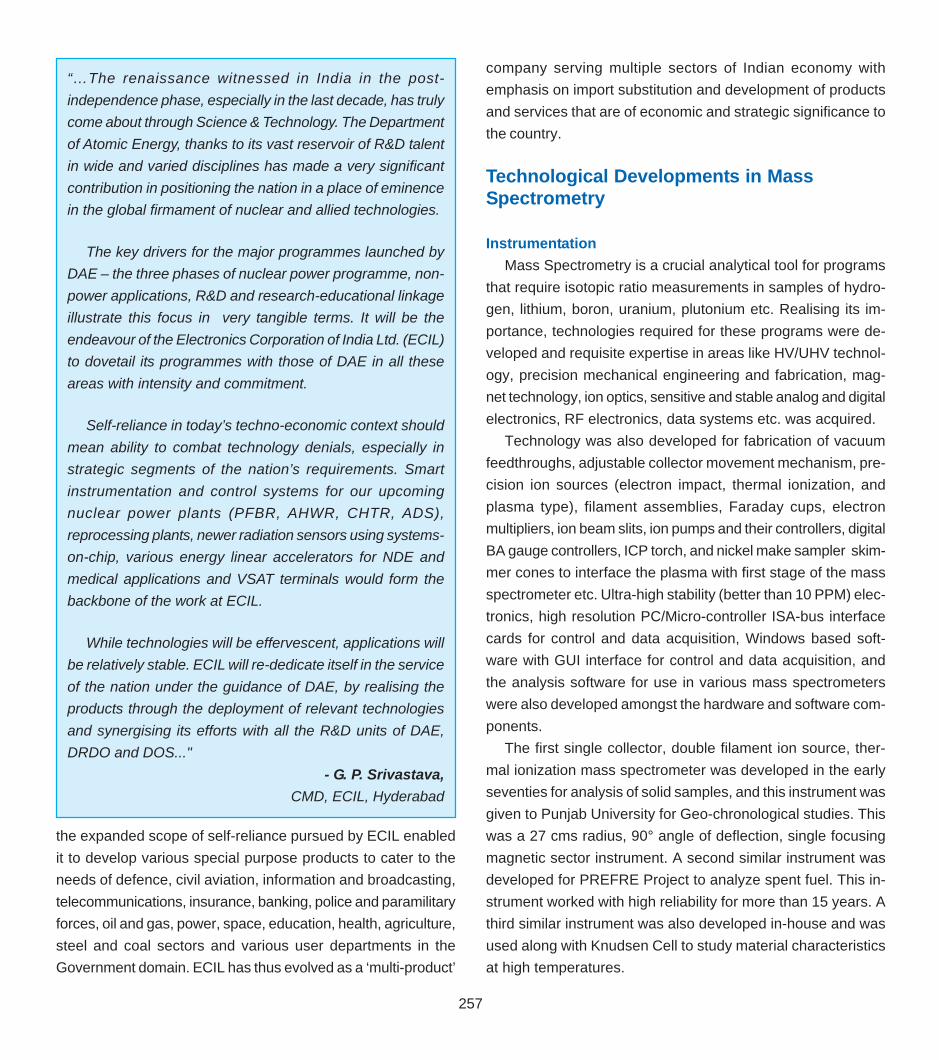
257
Cya
nMag
enta
Yello
wBl
ack
The
Cha
in R
eact
ion-
Volu
me
02 (P
art 0
3) #
150
Dt.:
29/1
0/20
05
CyanMagentaYellowBlack
the expanded scope of self-reliance pursued by ECIL enabled
it to develop various special purpose products to cater to the
needs of defence, civil aviation, information and broadcasting,
telecommunications, insurance, banking, police and paramilitary
forces, oil and gas, power, space, education, health, agriculture,
steel and coal sectors and various user departments in the
Government domain. ECIL has thus evolved as a ‘multi-product’
company serving multiple sectors of Indian economy with
emphasis on import substitution and development of products
and services that are of economic and strategic significance to
the country.
Technological Developments in MassSpectrometry
InstrumentationMass Spectrometry is a crucial analytical tool for programs
that require isotopic ratio measurements in samples of hydro-
gen, lithium, boron, uranium, plutonium etc. Realising its im-
portance, technologies required for these programs were de-
veloped and requisite expertise in areas like HV/UHV technol-
ogy, precision mechanical engineering and fabrication, mag-
net technology, ion optics, sensitive and stable analog and digital
electronics, RF electronics, data systems etc. was acquired.
Technology was also developed for fabrication of vacuum
feedthroughs, adjustable collector movement mechanism, pre-
cision ion sources (electron impact, thermal ionization, and
plasma type), filament assemblies, Faraday cups, electron
multipliers, ion beam slits, ion pumps and their controllers, digital
BA gauge controllers, ICP torch, and nickel make sampler skim-
mer cones to interface the plasma with first stage of the mass
spectrometer etc. Ultra-high stability (better than 10 PPM) elec-
tronics, high resolution PC/Micro-controller ISA-bus interface
cards for control and data acquisition, Windows based soft-
ware with GUI interface for control and data acquisition, and
the analysis software for use in various mass spectrometers
were also developed amongst the hardware and software com-
ponents.
The first single collector, double filament ion source, ther-
mal ionization mass spectrometer was developed in the early
seventies for analysis of solid samples, and this instrument was
given to Punjab University for Geo-chronological studies. This
was a 27 cms radius, 90° angle of deflection, single focusing
magnetic sector instrument. A second similar instrument was
developed for PREFRE Project to analyze spent fuel. This in-
strument worked with high reliability for more than 15 years. A
third similar instrument was also developed in-house and was
used along with Knudsen Cell to study material characteristics
at high temperatures.
“…The renaissance witnessed in India in the post-independence phase, especially in the last decade, has trulycome about through Science & Technology. The Departmentof Atomic Energy, thanks to its vast reservoir of R&D talentin wide and varied disciplines has made a very significantcontribution in positioning the nation in a place of eminencein the global firmament of nuclear and allied technologies.
The key drivers for the major programmes launched byDAE – the three phases of nuclear power programme, non-power applications, R&D and research-educational linkageillustrate this focus in very tangible terms. It will be theendeavour of the Electronics Corporation of India Ltd. (ECIL)to dovetail its programmes with those of DAE in all theseareas with intensity and commitment.
Self-reliance in today’s techno-economic context shouldmean ability to combat technology denials, especially instrategic segments of the nation’s requirements. Smartinstrumentation and control systems for our upcomingnuclear power plants (PFBR, AHWR, CHTR, ADS),reprocessing plants, newer radiation sensors using systems-on-chip, various energy linear accelerators for NDE andmedical applications and VSAT terminals would form thebackbone of the work at ECIL.
While technologies will be effervescent, applications willbe relatively stable. ECIL will re-dedicate itself in the serviceof the nation under the guidance of DAE, by realising theproducts through the deployment of relevant technologiesand synergising its efforts with all the R&D units of DAE,DRDO and DOS..."
- G. P. Srivastava,CMD, ECIL, Hyderabad

258
Cya
nMag
enta
Yello
wBl
ack
The
Cha
in R
eact
ion-
Volu
me
02 (P
art 0
3) #
150
Dt.:
29/1
0/20
05
CyanMagentaYellowBlack
Meanwhile, because of the use of heavy water moderator in
our nuclear power stations, mass spectrometry activity related
to the development of D/H mass spectrometers was initiated
and the first prototype, using electron impact ion source, was
developed in the mid seventies. This was a 6 cms. radius, 60°
angle of deflection, magnetic sector instrument built with two
collectors for simultaneous collection of mass 2 and mass 3
ion beams. The important features in this instrument were the
on-line dual sample introduction system and microprocessor
based isotopic ratio measurement system with H3+ compensa-
tion. These facilities were not available even in the imported
instruments at that time. Because of its performance, this in-
strument became highly popular. Three similar instruments were
made for various applications like enrichment studies etc. Simi-
lar instruments were needed for use in heavy water plants to
measure isotopic ratio of mass 2 and mass 3 and to determine
the enrichment of deuterium. More than a dozen such instru-
ments were fabricated since the first prototype was made and
installed in Heavy Water Plants at Manuguru, Thal, Hazira and
Kota. Some of these instruments are still in use and over the
years these have been upgraded to enhance reliability, preci-
sion of measurement, PC based analysis etc.
Stigmatic focusing was introduced in the isotopic ratio mass
spectrometers around this time. The triple collector instruments
using electron bombardment ion source, 27 cms radius, 90°
angle of deflection, and having mass resolution of about 100
were developed with two directional focusing. Following these
developments, one similar instrument along with an Argon Ex-
traction system was developed and supplied to Indonesian
Atomic Energy Agency for use in the quantitative measure-
ment of radiogenic Ar40 for age determination of rock samples.
Two other important developments that took place in the
mid seventies were fabrication of a normal geometry, 10 cms
radius, 90° bending angle, double collector thermal ionization
mass spectrometer for analysis of lithium nitrate samples to
determine lithium isotopic ratios, and construction of a quadru-
pole mass spectrometer which could analyze masses upto 150
AMU. In fact, this mass spectrometer for lithium isotopes is still
being used.
While the earlier version of quadrupole mass spectrometer
(QMS) used 8 mm diameter, 20 cms rods placed in stainless
steel mount, with tube based electronics for RF (3 MHz operat-
ing frequency), the newly made RF supply is fully solid state. It
supports the 16 mm diameter, 20 cms long rods placed in a
ceramic mount. Provision is also made for pre and post filters.
A residual gas analyzer, as a byproduct of QMS development,
is also in an advanced stage of development.
In the mid eighties, with the setting up of Rare Materials
Plant at Mysore, work was initiated towards the development
of triple collector, electron impact ion source mass spectrom-
eters to analyze the process gases. Two such instruments were
developed and installed. These are 30 cms radius, 90° bend-
ing angle stigmatic focusing instruments with resolution of 400
AMU and with on-line sample introduction system where stan-
dard and sample gases are analyzed alternately. These instru-
ments are still operational and thousands of samples have been
analyzed during the last decade.
Another set of multi-collector thermal ionization mass spec-
trometers with improved specifications was also developed for
analysis of solid samples. This was so because of the require-
ments in our reprocessing plants to carry out isotopic analysis
of nuclear materials. These instruments are also 30 cms. ra-
dius, 90° bending angle, stigmatic focusing instruments with
resolution of 400 AMU. However, these have maximum of five
collectors, 4 movable and 1 fixed, such that uranium and pluto-
nium sample analysis can be done with adjustments in the col-
lector positions. Multiple samples are loaded in the turret inter-
Indigenous Mass Spectrometer in use at BARC

259
Cya
nMag
enta
Yello
wBl
ack
The
Cha
in R
eact
ion-
Volu
me
02 (P
art 0
3) #
150
Dt.:
29/1
0/20
05
CyanMagentaYellowBlack
faced to the ion source for high throughput of the sample analy-
sis. The first such instrument was delivered to RMP, Mysore.
This was followed by second instrument to AFFF, Tarapur, and
third one to KARP, Kalpakkam. These instruments include au-
tomated heating of triple filaments for generation of ions be-
sides scan control and data acquisition using a GUI interface.
A new and improved thermal ionization mass spectrometer is
under development.
A large number of leak detectors, with a sensitivity of 10-11
std cc/sec, were also developed and used in various projects.
In fact, the same leak detectors are being used presently for
detection of leaks in our UHV systems and the technology of
these leak detectors was transferred to IBP, Mumbai in the early
eighties.
As part of technology development, a double focusing mass
spectrometer using Matsuda geometry, torroidal magnetic sec-
tor, and homogeneous magnetic sector was also developed at
BARC. The maximum resolving power of about 6000 was ob-
tained with this instrument.
The other mass spectrometer developed recently, for trace
and ultra trace elemental analysis, is the inductively coupled
plasma ion source mass spectrometer (ICP- MS) using
quadrupole analyzer. Due to its excellent detection limits, multi-
element capabilities, high sample throughput, and ability to
obtain isotopic information in the analyte elements, this machine,
which was completed recently, has become an important
analytical tool. Detection limits of 1 part per billion (ppb) are
achieved for some of the elements like Cs and Au. The RF
generator (2.5 kW ≅ 27.12 MHz), quadrupole mass
spectrometer with its RF and DC power supplies, PC based
control and data acquisition both in analog and pulse counting
modes of operation have been developed in-house.
Laser Induced Vapourization Mass Spectrometry (LIVMS)
is an important technique for measuring vapor pressures at
high temperatures, one of the key parameter in hypothetical
core disruptive accident analysis. LIVMS and Laser-Ionization
Reflectron Time-of-Flight Mass Spectrometer (RTOFMS) were
developed in-house during the last 10 years. Apart from ex-
perimental uniqueness and cost effective import substitutes,
both systems are working successfully over the last several
years with no maintenance shutdowns.
Intelligent Process Instrumentation SystemsProcess instrumentation systems for nuclear reactors can
be classified into three major categories; Operator information
systems, Control systems and Protection systems. Operator
information systems mainly acquire various process parameters
and display them. The function of the control systems is to
monitor process parameters and take corrective action
whenever they deviate from their set values. The functions of
the protective systems are to shutdown the reactor and provide
emergency cooling, under certain abnormal conditions, in order
to protect the public from radioactive exposure. In the past,
these systems were made using relays and integrated circuits.
The displays were mainly indicating meters and strip-chart
recorders.
With the introduction of microprocessors and personal
computers, the design of the process instrumentation systems
has undergone revolutionary changes leading to more reliable
systems.
DHRUVA was the first research reactor, where design of
computer based systems was taken up. Dual processor based
Alarm Annunciating System (AAS) was commissioned at
DHRUVA in 1982. Subsequently microprocessor based data
acquisition system for displaying important reactor parameters
was commissioned. This system displays plant data in graphi-
cal format on colour CRTs.
After the induction of computer based systems in DHRUVA
and based on the feedback, development work was undertaken
In-house developed Laser Mass spectrometer facility at IGCAR

260
Cya
nMag
enta
Yello
wBl
ack
The
Cha
in R
eact
ion-
Volu
me
02 (P
art 0
3) #
150
Dt.:
29/1
0/20
05
CyanMagentaYellowBlack
for deploying such operator information systems in power plants.
The first 8085 (8-bit microprocessor) based Channel Tempera-
ture Monitoring (CTM) system was commissioned at MAPS-1
in 1984. This system displays values of the channel outlet tem-
perature on a CRT. The operator could also take a hard copy
print out for records. Realizing its advantages, a similar sys-
tem was commissioned at MAPS-2 in 1986. For displaying plant
information, Data Acquisition Systems (DAS) were connected
in STAR topology for MAPS-1, BUS topology for MAPS-2 and
in ETHERNET LAN for RAPS-2.
With the usage of computers in operator information systems,
confidence was gained and computer based control systems
were designed. For the first time, 8085 based Reactor
Regulating System (RRS) was designed and commissioned at
Narora Atomic Power Station (NAPS-1) in 1986. The function
of this control system is to maintain reactor power output at the
value set by the operator. Also computer based Fuel Handling
Control System (FHCS) was designed and commissioned at
NAPS. The system was used to carry out on-line refuelling of
the reactor. Control Room Computer System (CRCS), was
designed and commissioned at NAPS-1 to view all important
process and nuclear parameters on multiple colour graphics
terminals in the control room. Based on the feedback at MAPS
and NAPS, more and more systems were computerized. The
first reactor protection system viz. Programmable Digital
Comparator System (PDCS) was designed and commissioned
at Kakrapar Atomic Power Station (KAPS-1) in 1990. This
system mainly monitors important process parameters and
generate alarms and reactor set back/trip outputs whenever
any parameter deviates from the set limit.
As the development of computer based systems for power
plants were going on, extensive computerization was done for
the control, process interlock and alarm annunciation functions
of KAMINI.
Around this time, as computers were being inducted into
systems important to safety of the reactor, a review on the
system architecture was done. More emphasis was placed on
reliability (of both hardware and software) and availability. This
has led to Dual Processor Hot Standby (DPHS) architecture.
Self-test features to detect hardware and software failures were
added to the systems. A process control system for control of
reactor primary and secondary loop parameters based on this
architecture (DPHS_PCS) was designed and commissioned
at Kaiga and Rajasthan Atomic Power Station (RAPS-3&4) in
1999. Also RRS was designed and commissioned at Kaiga
and Rajasthan Atomic Power Station (RAPS-3&4) based on
this architecture.
A 16-bit Trombay Digital Computer (TDC-316) based fault-
tolerant data acquisition system was supplied during 1985 for
Fast Breeder Test Reactor to supervise the coolant flow through
each fuel sub-assembly. If the temperature rise exceeds the
set limit, the computer will initiate ‘SCRAM’ signal to shut-down
the reactor. The software was developed in assembly language.
The aged TDC-316 systems were replaced with 32 bit
UNIPOWER system. Supervision software was rewritten in C
language. Besides the usual display of trend of process signals,
Human Machine Interface System of FBTR provides the vital
information regarding the thermal balance and reactivity balance
of the reactor.
Realizing the potential of computer based systems, a
Disturbance Recording system (DRS) was designed that not
only acquires the plant data but also stores it and helps in its
transient analysis at a later time. Today, all the power reactors
starting from MAPS deploy this system for analysis. Further, it
was observed that, in a power plant, whenever multiple alarms
are annunciated in the control room, the operators find it difficult
to get to the root cause of such alarms. In order to help operators
under such conditions, an Event Sequencing Recorder (ESR)
was designed and commissioned at Kaiga and Rajasthan
Atomic Power Station (RAPS-3&4). This system can resolve
events at a resolution of 1 millisecond.
Human Machine Interface System at FBTR

261
Cya
nMag
enta
Yello
wBl
ack
The
Cha
in R
eact
ion-
Volu
me
02 (P
art 0
3) #
150
Dt.:
29/1
0/20
05
CyanMagentaYellowBlack
With enough knowledge and experience gained while work-
ing on these systems, the stage was set for embarking on net-
working of computers. Hence work was started to design a
Supervisory Control And Data Acquisition (SCADA) system for
electrical equipments. This was commissioned at RAPS-3&4.
Based on a similar concept, a Vibration Monitoring System was
designed and commissioned at Kakrapar Atomic Power Sta-
tion to study and analyze turbine vibrations.
Many utility systems were also computerized and retrofitted
into the operating plants. One such system was Rod Worth
Minimizer System (RWMS). It checks the sequence of
withdrawal of control rods for proper control of the reactor. A
network based multimodel RRS has been developed for 540
MWe TAPP-3&4 reactors.
For FBR, triplicated single board computer (SBC) based
supervision and control systems are developed for supervising
the flow through each fuel subassembly, clad hot spot and power
excursion through the core. Analog input multiplexer card, digi-
tal input card, digital output card, analog output card, synchro
to digital converter card etc have been developed for various
back plane buses like Multibus, VME bus etc. For FBR, fault
tolerant SBC based systems were also developed for check-
ing the reactor start-up conditions, checking the logic for the
operation of control rods and fuel handling machines.
Safety features like ground isolation for analog input signals,
digital input signals, and digital output signals are provided.
Sensor validation, signal validation, signal linearisation etc are
performed by the embedded software. On-line diagnostics
checks the health of the hardware and proper functioning of
the signal processing routines. 'Fail Safe' feature is incorporated
wherein any hardware or software fault will result in generation
of 'trip' order to the plant. Diverse and redundant computer
based systems are used to ensure high reliability. The entire
embedded software consisting of Power on Self Test (POST),
monitor, signal processing routines, communication software,
online diagnostics etc have been developed satisfying
MISRA-C guidelines.
Precise Position Control System & Electronic GearingSpecial control electronics and control algorithm are
employed to stabilize the rotor of normal stepper motor at any
desired position in between the natural step angle of 1.8o. The
above concept has been developed in 1987-1988 and so far
0.018o of angular rotor positional resolution has been obtained,
which has been verified by optical interroferrometry. This is
now covered under the Indian Patent No. L-17595/98.
Automated Testing and Easy Maintenance of PlantC&I Systems
Thousands of standard 4-20 mA current loops are employed
in a nuclear plant to instrument physical parameters to view or
control important variables (pressure, temperature neutronics
etc). To calibrate and test each of them during plant
commissioning or plant shutdown maintenance is cumbersome
and prone to errors while performing manually.
To avoid this, one needs to use an instrument where live
field 4-20 mA signals are injected on test input, without
disconnecting field input wires. This process only changes the
input current of system under test locally without disturbing the
loop current. Handheld prototype instrument under patent
SCADA system for RAPS-3 and 4
Indigenously developed instrumentation and control cards

262
Cya
nMag
enta
Yello
wBl
ack
The
Cha
in R
eact
ion-
Volu
me
02 (P
art 0
3) #
150
Dt.:
29/1
0/20
05
CyanMagentaYellowBlack
No. MUM/282/2001 is now being used at KAIGA, for carrying
out plant maintenance and testing.
Evolution of Training SimulatorsTraining simulator helps the operating staff to be fully famil-
iar with various control and operation of nuclear reactor plants,
before they actually carry out the task. Application simulators
in the nuclear power plant training programs had their incep-
tion in the early 1980s. Full Scope Training Simulators were
developed and commissioned at Kaiga Power Plant and RAPS
3&4. Similar simulators are in the process of development for
TAPS 3&4. and the 500 MWe FBR.
Design of a training simulator requires multi-disciplinary
knowledge. Computer simulation represents application of
mathematical models to real systems to derive its characteris-
tics and behaviour without actually constructing or operating
the system concerned. To build training simulators, the sub-
systems and components, which contribute towards plant dy-
namics and those associated with the operation and control
functions of the reactor are identified to start with. Their indi-
vidual behaviour and the interlinking among them are math-
ematically modeled. This mathematical model is then trans-
lated into simulation software that will eventually run in the simu-
lator computer.
Development of simulation software is very challenging be-
cause it has to scan inputs from operator activated control pan-
els, process it in accordance with the plant model in real time
and give the computer generated outputs on the control panel
by actuating the appropriate devices or their equivalents. Nor-
mally, this software also supports an instructor station from
which a training instructor can interact with the computer soft-
ware to give appropriate training lessons to the operator, insert
different plant scenarios, monitor the operator response and
evaluate the performance.
Development of Supercomputer TechnologySupercomputers are extensively used for solving very large
computational problems for a variety of applications in scientific
research, engineering, industry and defense. There is ever
growing requirement of faster supercomputers for performing
more realistic calculations at a higher accuracy and also to
process larger amount of data in a given period of time. Since
even procuring ordinary, high-speed computers for various R
& D units of DAE has all along been a major problem due to the
sanctions imposed under technology control regime by the
advanced countries, there was absolutely no possibility of
procuring supercomputers for DAE. At the national level, the
country succeeded in procuring a CRAY dual X/MP
supercomputer from USA, for medium range weather
forecasting applications, in 1988. This was supplied to the
National Centre for Medium Range Weather Forecasting
(NCMRWF), New Delhi, with many stringent conditions
restricting its use only for weather forecasting computations.
R & D in the field of designing supercomputers, primarily
for meeting supercomputing requirements of DAE was, there-
fore, initiated in 1990. The first supercomputer ANUPAM-860/
4, giving a sustained speed of 30 Million Floating Point Instruc-
tions Per Second (MFLOPS), was built in December 1991. It
was an achievement of great significance for the scientists and
engineers in DAE. Once the breakthrough in building
supercomputers was achieved, it was followed up by a dedi-
cated and sustained effort towards developing faster, more re-
liable and more user friendly models in the subsequent years.
So far 18 different models have been built, the latest being
ANUPAM-Aruna, developed in July 2003, having a computing
speed of 358 Giga flops, which is more than 10,000 times faster
than the first ANUPAM. All along, the ANUPAM series of
supercomputers has not only been far better in performanceFull-scale training simulator at Kaiga, which helps to train the
manpower for reactor operation

263
Cya
nMag
enta
Yello
wBl
ack
The
Cha
in R
eact
ion-
Volu
me
02 (P
art 0
3) #
150
Dt.:
29/1
0/20
05
CyanMagentaYellowBlack
than similar supercomputers available from abroad as well as
other indigenous sources, but has also been highly cost-effec-
tive, reliable and user friendly. These supercomputers have
been used by DAE units, and many leading R & D and educa-
tional institutes in the country such as Aeronautical Develop-
ment Agency (ADA) Banglore, Vikram Sarabhai Space Cen-
tre, Thiruvananthapuram, National Centre for Medium Range
Weather Forecasting (NCMRWF) New Delhi, Nuclear Power
Corporation, Mumbai, IIT, Mumbai, IIT, Kanpur, UICT, Mumbai
and SNDT, Mumbai.
The areas of research in which these have been deployed
for solving many large computational problems, which other-
wise could not have even been attempted, include, inter alia,
condensed matter physics simulations, molecular dynamics
simulations, crystal structure analysis, high energy physics data
analysis, first principle electronic structure studies, protein
molecule structures, plasma simulations, radiation chemistry
computations, atmospheric chemistry computations, radiation
hydrodynamics, computational fluid dynamics, finite element
structure analysis, neutron transport computations, laser-atom
interactions and gamma ray simulations.
Major applications of ANUPAM systems outside DAE, have
been in the field of weather forecasting for National Centre for
Medium Range Weather Forecasting (NCMRWF), Delhi and
computational fluid dynamics for Aeronautical Development
Agency (ADA), Bangalore. One ANUPAM-Alpha supercomputer
is being used for operational runs on a regular basis for me-
dium range weather forecasting, replacing the obsolete CRAY
dual X/MP supercomputer at NCMRWF, since December, 1999.
ADA has been using various models of ANUPAM series
supercomputers for solving problems related to the design of
Light Combat Aircraft (LCA) since 1994. One ANUPAM-Pentium
III supercomputer was commissioned at ADA in June 2000.
The ANUPAM series of supercomputers are based on
parallel processing technology for achieving supercomputing
speeds, which emerged as an alternative to the conventional
method of building hardware-based supercomputers, in the late
80’s. The conventional supercomputers make use of the fastest,
cutting edge electronics and many advanced architectural
features involving enormous amount of proprietary hardware
to achieve the maximum possible speed of execution. The
parallel processing technique, on the other hand, makes use
of a number of high speed, conventional processors,
interconnected by a communication network. A single large job
is divided into smaller, independently executable modules which
are run on various processors of the parallel processing
supercomputer, in a coordinated fashion so that the large job is
executed in a much shorter period of time.
Since the usage of parallel supercomputer requires addi-
tional effort of parallelising the computational jobs, any parallel
supercomputer system has to be reasonably faster than the
fastest sequential computer available at any period of time.
Also its operating system, compilers, utilities have to be very
similar to the one being already used by the users, so that the
user’s effort in parallelising is minimal. The design of the
supercomputer has to be based on industry standard compo-
nents in order to keep the cost low and to achieve very high
reliability of operation. The time required for building the sys-
tem has to be kept very short, otherwise due to very rapidly
advancing technology of microprocessors, the speed of the lat-
est available sequential computer may out-match the speed of
parallel supercomputer.
In 1991, BARC was using indigenously manufactured mini-
computers based on Intel’s 80860 RISC microprocessor oper-
ating at 40 MHz., giving a user speed of 8 MFLOPS for scien-
ANUPAM-86064-node
Sustained speed on 64 nodes 400 million flopsYear of introduction 1995

264
tific jobs. It was decided to use Intel’s 80860 based central pro-
cessor module of this minicomputer as computer node in the
parallel supercomputer as it was already available and it was
giving fastest computational speed. Initially the parallel process-
ing system was developed using one master processor and 4
slave processors, with Multibus II for intercommunication, in
December 1991. Addition of more nodes took the speed of ex-
ecution to 52 MFLOPS in August 1992.
The system was further upgraded to 16 nodes, in November,
1992, by coupling two minicomputer chassis with 8 nodes each,
using a Multibus-to-Multibus parallel intercommunication link
operating at 20 Mbps, giving a sustained speed of 110 MFLOPS.
The system was upgraded to 32 nodes in February, 1994.
Subsequently another 32 processor system using two chassis
with 16 slave processor each, based on the latest Intel’s 860/
XP, operating at 50 MHz with many advanced features, giving
a speed of 389 MFLOPS was built in May, 1995. The two 32
processor parallel systems were later on interconnected, to
make a 64-node parallel supercomputer giving a user speed of
407 MFLOPS on 64 processor system, in November 1995. The
speed of this system was same as CRAY Y/MP vector
supercomputer.
Subsequently, it was decided to build ANUPAM systems us-
ing cluster technology, which makes use of dedicated worsta-
tions interconnected by a high speed communication network.
A 6-node ANUPAM-Alpha, using 6 work stations based on Al-
pha 21164 microprocessor, operating at 400 MHz, intercon-
nected by the industry standard Asynchronous Transmission
Communication (ATM) switch operating at 155 Mbps, was built
in July, 1997. The sustained speed achieved on the 6-node
ANUPAM Alpha was 970 million flops, which was more than
twice the speed of the 64-node ANUPAM-860 built in 1995.
This system was further upgraded to 10-node system, giving a
speed 1527 MFLOPS, in March, 1999.
Since Alpha 21164 microprocessor based work stationswere
very costly, in order to build supercomputers at low cost, it was
ANUPAMANUPAM-- Alpha and ANUPAMAlpha and ANUPAM-- Pentium InstallationsPentium Installations
Sustained SpeedBARC, MUMBAI
ANUPAM-ARUNA (128-node Linux) 358 Giga FlopsANUPAM-ASHWA (64 -node Linux) 71 Giga Flops
NCMRWF, NEW DELHIANUPAM-ALPHA/600 (8 node) 1.2 Giga Flops
VSSC THIRUVNHAPURAMANUPAM-ALPHA/600 ( 8-node) 1.2 Giga FlopsANUPAM-PIII/550 (16-node Linux) 3.5 Giga Flops
IIT, MUMBAIANUPAM-ALPHA/400 ( 4-node) 0.5 Giga FlopsANUPAM-PIII/550 (8-node Linux) 1.8 Giga Flops
M S UNIVERSITY, BARODAANUPAM-PII (4-node) 0.3 Giga Flops
ADA, BANGLOREANUPAM-PIII/550 (16-node Linux) 3.5 Giga Flops
NPC, MUMBAIANUPAM-PIII/550 (16-node Linux) 3.5 Giga Flops
IIT, KANPURANUPAM-PIII/550 (8-node Linux) 1.8 Giga Flops
UDCT, MUMBAIANUPAM-PII (4-node) 0.3 Giga Flops


266
Cya
nMag
enta
Yello
wBl
ack
The
Cha
in R
eact
ion-
Volu
me
02 (P
art 0
3) #
150
Dt.:
29/1
0/20
05
CyanMagentaYellowBlack
computer nodes was built using 64 dual servers and Scalable
Coherent Interface (SCI), a new interconnect technology. Each
server was based on a dual Xeon, 2.4 GHz processors with 2
GB memory and 40 GB hard disk. SCI, the intercommunication
network gave node to node communication speed of 300
megabytes per second and a very low latency of 3.5
microseconds, as compared to the speed of 40 megabytes per
second and a latency of 100 microseconds achievable using
Gigabit Ethernet. This supercomputer built in August 2003, with
128 Xeon processors and SCI gave a benchmark speed of
360,000 MFLOPS on the High Performance Linpack
benchmark.
The ANUPAM series of systems are based on multiple
instruction, multiple data (MIMD), distributed parallel processing
architecture. The system consists of a master node and a
number of computer nodes called slave nodes. For running on
a parallel system, a user program is divided into a main partition
and a number of slave partitions, which can be executed
independently. The main partition is executed on the master
node, and the other partitions are executed on the slave nodes
under the control of master task and slave task programs. The
master task program starts execution on all the processors,
transfer data, coordinating the multiple executions going on
simultaneously, through intercommunication calls embedded
in the various partitions of the user program and finally collects
the results from slaves. The master task also controls I/O and
all other functions related to the execution of any program in a
general computing environment. The slave task functions are
limited to receiving the control commands from the master,
data transfer and execution of their partitions in coordination
with the Master task. The communications between the master
task and the slave tasks are carried out explicitly, through
message passing calls using intercommunication network. The
message passing calls are implemented as set of library calls,
named ANULIB, for both FORTRAN and C programs using
standard network protocols TCP/IP, so that any industry
standard network could be used for building the parallel system.
In the later versions, PVM and MPI, other industry standard
libraries for message passing have also been implemented.
The other software tools provided on ANUPAM systems were,
user program profiler, program flow analyser, debugger for
parallel program syntax checker, utilities for tracing run time
error and semi-automatic parallisation compiler and parallel
simulator.
Along with improvements in the computational speed of the
ANUPAM series of supercomputers, a number of software
packages were also developed to enhance its utility, to increase
its user base and to facilitate handling of very large clusters.
An auto installer was developed to speed up the process of
installing the operating systems and other software packages
on computer nodes in a large cluster. In a large cluster, there
are problems of nodes malfunctioning due to hardware faults
or run away situations due to some software faults. A software
package for detecting and isolating faulty/run away nodes was
implemented. Also in a large cluster, parallel jobs may be
running with varying requirements of resources in terms of
nodes. For submitting user jobs in a controlled fashion, a parallel
job scheduler was developed, which keeps track of the free
nodes available for use at any period of time and schedule the
parallel jobs automatically and also in predefined time schedule,
so that all the resources of the cluster are utilized in optimum
and controlled fashion. A parallel file system for processing large
jobs with very large data was developed in collaboration with
IIT Mumbai. This file system distributes the large data file to
local disks of nodes in the parallel system, thus permitting local
computations on large data files in the compute nodes, without
the need of communicating with a single master file thus
ANUPAM-Aruna128 node
Sustained speed on 128 nodes 358,000 Million FlopsYear of introduction 2003

267
Cya
nMag
enta
Yello
wBl
ack
The
Cha
in R
eact
ion-
Volu
me
02 (P
art 0
3) #
150
Dt.:
29/1
0/20
05
CyanMagentaYellowBlack
avoiding choking of the intercommunication network of the
parallel system. Anupam is also being used for deciphering
structures of biological macromolecules such as proteins.
Scalable Graphics System with High Resolution TiledDisplay
As the processing power and memory capabilities of
supercomputers continue to increase, the size of data, required
to be visualized, is becoming very large. In many scientific
applications, it is important to view large amount of data in details
for comprehensive understanding of the behaviour of various
computer simulations. Visualisation of terascale scientific data
in a distributed environment at a very high resolution and high
rendering speed is a big challenge.
Normally, interactive visualization applications are limited to
the use of a single high speed graphics system with a display
resolution of the order of 1920*1200 pixels. For visualising large
amount of data, windowing techniques are used, limiting the
view to a small window with a resolution limited to a single
display. The other approach for viewing large data with higher
resolution, is to use high-performance tightly integrated graphics
computer system connected to multiple video outputs. This type
of large screen displays besides being very costly, are also not
available from abroad due to sanctions.
A scalable display wall using cluster of graphics workstation
connected in a high-speed network was developed for viewing
large amount of data with much higher pixel resolution and a
high rendering speed. The system comprises sixteen Pentium
IV based graphics workstations, each driving a LCD monitor
with a resolution of 1280 by 1024 pixels. All the 16 monitors
are arranged in a 4 by 4 grid to form a large seamless image
with a cumulative resolution of 5120 by 4096 pixels. The 16
graphics servers, interconnected by Giga bit Ethernet are
controlled synchronously by one master client node. In this way
both the resolution and the graphics power for rendering speed
is scaled as each graphics system corresponds to each tile in
the large display wall. Here the primary challenge is to construct
rendering strategies that work effectively within the processing,
storage and bandwidth characteristics of commodity
components. This type of display may fulfill total immersion
demand, where the user is surrounded by multiple flat tiled
displays. This system has been developed on the Linux
environment Applications for viewing high resolution images,
movies, scientific data and scenes defined by VRML2 language
on the large tiled display are available on this system. A
graphical control panel has been developed for controlling all
graphics servers from a central master client for administration
purpose.
Enabling technologies, thus, encompass a wide spectrum
of activities ranging from NDE techniques for inspection of
critical components both in-service as well as post-irradiation,
robotics and remote handling devices, laser based devices,
process instrumentation, chemical sensors and large scale
Protein molecule structure Weather forecasting

268
Cya
nMag
enta
Yello
wBl
ack
The
Cha
in R
eact
ion-
Volu
me
02 (P
art 0
3) #
150
Dt.:
29/1
0/20
05
CyanMagentaYellowBlack
High resolution tiled display
computers with enhanced number crunching capabilities. It is
a synergistic and all round developments in these areas that
has catalysed the growth of nuclear power and the associated
fuel cycle facilities. Advances in each of these areas have also
contributed significantly in improving the sophistication and
reliability of various components being used in nuclear industry
as well as in other strategic and core sectors.