Embed Size (px)
Citation preview

ManualEN
VMD420-DM
Voltage and frequency monitorfor monitoring of 3(N)AC systems up to 0…500 Vfor undervoltage and overvoltage and under and overfrequencySoftware version: D238 V2.2x
VMD420-DM_D00227_01_M_XXEN/07.2015

Bender GmbH & Co. KGLondorfer Str. 65 • 35305 Gruenberg • GermanyPostfach 1161 • 35301 Gruenberg • Germany
Tel.: +49 6401 807-0Fax: +49 6401 807-259
Email: [email protected] www.bender.de
© Bender GmbH & Co. KG
All rights reserved.Reprinting only with permissionof the publisher.Subject to change!
Photos: Bender archives

Table of Contents
1. How to use this documentation effectively ................................................ 5
2. Safety .................................................................................................................. 72.1 General ................................................................................................................. 72.2 Intended use ...................................................................................................... 72.3 Skilled person .................................................................................................... 72.4 Safety information on work activities on electrical installations .... 8
3. Function ............................................................................................................. 93.1 Device features ................................................................................................. 93.2 Function ............................................................................................................... 93.2.1 Preset function ............................................................................................... 103.2.2 Automatic self test ........................................................................................ 113.2.3 Manual self test .............................................................................................. 113.2.4 Functional faults ............................................................................................ 113.2.5 Fault memory ................................................................................................. 113.2.6 Start-up delay t ............................................................................................... 123.2.7 Password protection (on, OFF) ................................................................. 123.2.8 Factory setting FAC ...................................................................................... 123.2.9 Erasable history memory ............................................................................ 123.2.10 Interface option M ........................................................................................ 123.2.11 Menu item AnA for interface configuration ........................................ 13
4. Installation, connection and commissioning ........................................... 154.1 Fast commissioning for Un = 400 V, 50 Hz ........................................... 154.2 Installing the device ..................................................................................... 174.2.1 DIN rail mounting .......................................................................................... 174.2.2 Screw fixing ..................................................................................................... 17
3VMD420-DM_D00227_01_M_XXEN/07.2015

Table of Contents
4.3 Wiring of the device ..................................................................................... 184.4 Commissioning preset function/factory setting ................................ 19
5. Operation and setting .................................................................................. 215.1 Getting to know the user interface ......................................................... 215.2 Understanding of standard display indications ................................. 225.3 Getting to know keys and key functions .............................................. 235.4 Querying values ............................................................................................. 245.5 Starting the self test manually .................................................................. 255.6 Clearing the fault memory ......................................................................... 265.7 Calling up or leaving the menu ................................................................ 265.8 Carrying out settings in the menu .......................................................... 265.8.1 Selecting menu items .................................................................................. 265.8.2 Carrying out settings in the menu item AL .......................................... 285.8.3 Carrying out settings in the menu item out ........................................ 325.8.4 Carrying out settings in the menu item t ............................................. 365.8.5 Carrying out settings in the menu item SEt ......................................... 375.8.6 Querying information in menu item INF .............................................. 405.8.7 Querying and clearing fault memory in the menu item HIS ......... 41
6. Technical data ................................................................................................ 436.1 Data in tabular form ..................................................................................... 436.2 Current and voltage curves of the analogue interface .................... 476.3 Standards, approvals and certifications ................................................ 486.4 Ordering information ................................................................................... 48
INDEX .................................................................................................................... 49
4 VMD420-DM_D00227_01_M_XXEN/07.2015

1. How to use this documentation effectively
This manual is intended for experts in electrical engineering and electronics!In order to make it easier for you to find specific text passages or references inthis manual and for reasons of comprehensibility, important information is emphasized by symbols. The meaning of these symbols is explained below:
The signal word indicates that there is a high risk of dangerthat will result in electrocution or serious injury if notavoided.
This signal word indicates a medium risk of danger that canlead to death or serious injury if not avoided.
This signal word indicates a low level risk that can result inminor or moderate injury or damage to property if notavoided.
This symbol denotes information intended to assist the userto make optimum use of the product.
DANGER
WARNING
CAUTION
5VMD420-DM_D00227_01_M_XXEN/07.2015

How to use this documentation effectively
6 VMD420-DM_D00227_01_M_XXEN/07.2015

2. Safety
2.1 GeneralIn addition to this manual, the documentation of the device includes a docu-ment entitled "Important safety instructions for Bender products“.
2.2 Intended useThe voltage monitor VMD420 monitors 3(N)AC systems in the frequency range 15…460 Hz for undervoltage, overvoltage, underfrequency and over-frequency. The devices are designed for the nominal voltage range Un = 0…500 V. Separate supply voltage Us is required.
2.3 Skilled personOnly electrically skilled persons are authorised to install and commission this device. Electrically skilled persons are those who have the relevant education, knowledge and experience, as well as knowledge of the relevant safety stand-ards and who are able to perceive risks and to avoid hazards which electricity can create when work activities are carried out on electrical installations. The electrically skilled person is specially trained for carrying out work activities in his specific working environment and has a thorough knowledge of the rele-vant standards and regulations.
In Germany, an electrically skilled person must meet the requirements of the accident prevention regulation BGV A3. In other countries the applicable reg-ulations have to be observed and followed.
7VMD420-DM_D00227_01_M_XXEN/07.2015

Safety
2.4 Safety information on work activities on electrical installations
Danger of electric shock!Unprofessional work activities on electrical installations mayresult in a threat of danger to life and limb!All work activities on electrical installations as well asinstallation activities, commissioning activities and workactivities with the device in operation may only be carriedout by electrically skilled persons!
DANGER
8 VMD420-DM_D00227_01_M_XXEN/07.2015
3. Function
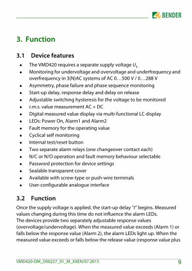
3.1 Device features The VMD420 requires a separate supply voltage Us Monitoring for undervoltage and overvoltage and underfrequency and
overfrequency in 3(N)AC systems of AC 0…500 V / 0…288 V Asymmetry, phase failure and phase sequence monitoring Start-up delay, response delay and delay on release Adjustable switching hysteresis for the voltage to be monitored r.m.s. value measurement AC + DC Digital measured value display via multi-functional LC display LEDs: Power On, Alarm1 and Alarm2 Fault memory for the operating value Cyclical self monitoring Internal test/reset button Two separate alarm relays (one changeover contact each) N/C or N/O operation and fault memory behaviour selectable Password protection for device settings Sealable transparent cover Available with screw-type or push-wire terminals User-configurable analogue interface
3.2 FunctionOnce the supply voltage is applied, the start-up delay "t" begins. Measured values changing during this time do not influence the alarm LEDs.The devices provide two separately adjustable response values (overvoltage/undervoltage). When the measured value exceeds (Alarm 1) or falls below the response value (Alarm 2), the alarm LEDs light up. When the measured value exceeds or falls below the release value (response value plus
9VMD420-DM_D00227_01_M_XXEN/07.2015

Function
hysteresis), the alarm LEDs go out. When the fault memory is activated, the alarm LEDs remain in the alarm state until the reset button R is pressed.
3.2.1 Preset functionAfter connecting the system to be monitored for the first time, the response values for overvoltage and undervoltage (Alarm 1/2) are automatically set once to:Response value overvoltage ( > U): 1.1 Un Response value undervoltage ( < U): 0.85 Un Response value overfrequency ( > f) at 16.7 Hz, 50 Hz, 60 Hz: fn + 1 HzResponse value overfrequency ( > f) at 400 Hz: fn + 1 HzResponse value underfrequency ( < f) at 16.7 Hz, 50 Hz, 60 Hz: fn - 1 HzResponse value underfrequency ( < f) at 400 Hz: fn - 1 Hz
Preset VMD420-DM
Measuring principle Un
Presetoperating
range
Response value
< U
Response value
> U
Phase-to-phase volt-age measurement:
3Ph
400 V (L1, L2, L3)
340…440 V 340 V 440 V
208 V (L1, L2, L3)
177…229 V 177 V 229 V
Only when the preset function (Menu/SEt/PrE) has been started manually, the following response values can be set:
Phase-to-neutral volt-age measurement: 3n
230 V (L1, L2, L3, N)
196…253 V 196 V 253 V
120 V (L1, L2, L3, N)
102…132 V 102 V 132 V
10 VMD420-DM_D00227_01_M_XXEN/07.2015

Function
If the measured voltage is not within the preset operating range listed in the table, the message "AL not Set“ appears on the display. In this case, it is neces-sary to set the response values for Alarm 1 (AL1) and Alarm 2 (AL2) manually. A detailed description of the process is given in the chapter "parameter set-ting“.After restoring the factory settings, the preset function is automatically active again.During operation the preset function can be started manually via the menu SEt.
3.2.2 Automatic self testThe device automatically carries out a self test after connection to the system to be monitored and later every hour. During the self test internal functional faults are detected and will appear in form of an error code on the display.
3.2.3 Manual self testPressing the test button for > 1.5 s causes the device to carry out a self test where the internal functional errors are determined and shown on the display as error codes.While the test button T is pressed and held down, all device-related display el-ements appear on the display.
3.2.4 Functional faultsIf an internal malfunction occurs, all three LEDs flash. An error code will appear on the display (E01…E32). In such a case please contact the Bender Service.
3.2.5 Fault memoryThe fault memory can be activated, deactivated or can be set to continuous mode (con). If the fault memory is set to "con“ mode, the alarm parameters re-main stored even on failure of the supply voltage.
11VMD420-DM_D00227_01_M_XXEN/07.2015

Function
3.2.6 Start-up delay tOnce the supply voltage Us has been switched on, the alarm indication is de-layed by the preset time t (0…300 s).
3.2.7 Password protection (on, OFF)When password protection is enabled (on), settings can only be carried out af-ter entering the password (0…999). If you cannot operate your device be-cause you cannot remember your password, please contact [email protected].
3.2.8 Factory setting FACAfter activating the factory setting, all settings previously changed are reset to delivery status. In addition, the preset function allows automatic adaptation of the response values in relation to the nominal voltage Un.
3.2.9 Erasable history memoryThe first alarm value to occur is saved in this memory. Subsequent alarms do not overwrite this "old“ value. The memory can be cleared using the Clr key in the menu HiS.
3.2.10 Interface option MThis option provides an analogue interface with galvanic isolation, but does not provide an alarm relay. One of three output signals can be selected from the associated menu. Only the output that has been selected via software may be connected:
Output signal Purpose of use
DC 0…400 μA Current output for Bender measuring instruments of the 96.. series
DC 0/4…20 mA Standardised current output with selectable current ranges
DC 0…10 V Standardised voltage signal
12 VMD420-DM_D00227_01_M_XXEN/07.2015
Function
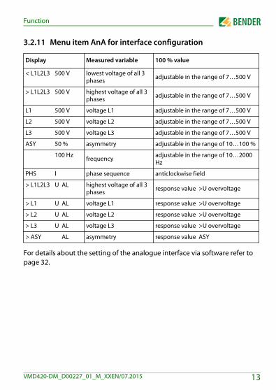
3.2.11 Menu item AnA for interface configuration
For details about the setting of the analogue interface via software refer to page 32.
Display Measured variable 100 % value
< L1L2L3 500 V lowest voltage of all 3 phases adjustable in the range of 7…500 V
> L1L2L3 500 V highest voltage of all 3 phases adjustable in the range of 7…500 V
L1 500 V voltage L1 adjustable in the range of 7…500 V
L2 500 V voltage L2 adjustable in the range of 7…500 V
L3 500 V voltage L3 adjustable in the range of 7…500 V
ASY 50 % asymmetry adjustable in the range of 10…100 %
100 Hz frequency adjustable in the range of 10…2000 Hz
PHS l phase sequence anticlockwise field
> L1L2L3 U AL highest voltage of all 3 phases response value >U overvoltage
> L1 U AL voltage L1 response value >U overvoltage
> L2 U AL voltage L2 response value >U overvoltage
> L3 U AL voltage L3 response value >U overvoltage
> ASY AL asymmetry response value ASY
13VMD420-DM_D00227_01_M_XXEN/07.2015

Function
14 VMD420-DM_D00227_01_M_XXEN/07.2015
4. Installation, connection and commissioning
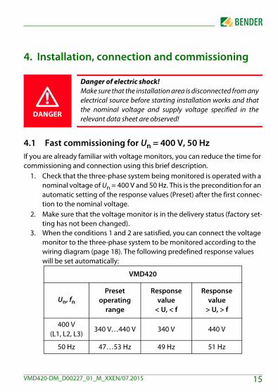
4.1 Fast commissioning for Un = 400 V, 50 HzIf you are already familiar with voltage monitors, you can reduce the time for commissioning and connection using this brief description.
1. Check that the three-phase system being monitored is operated with a nominal voltage of Un = 400 V and 50 Hz. This is the precondition for an automatic setting of the response values (Preset) after the first connec-tion to the nominal voltage.
2. Make sure that the voltage monitor is in the delivery status (factory set-ting has not been changed).
3. When the conditions 1 and 2 are satisfied, you can connect the voltage monitor to the three-phase system to be monitored according to the wiring diagram (page 18). The following predefined response values will be set automatically:
Danger of electric shock! Make sure that the installation area is disconnected from anyelectrical source before starting installation works and thatthe nominal voltage and supply voltage specified in therelevant data sheet are observed!
VMD420
Un, fnPreset
operating range
Response value
< U, < f
Response value
> U, > f
400 V (L1, L2, L3)
340 V…440 V 340 V 440 V
50 Hz 47…53 Hz 49 Hz 51 Hz
DANGER
15VMD420-DM_D00227_01_M_XXEN/07.2015

Installation, connection and commissioning
4. The currently measured phase-to-phase voltage between L1 and L2 appears on the display. Use the UP and DOWN keys to query other parameters:– phase-to-phase voltage L2, L3– phase-to-phase voltage L1, L3– asymmetry– system frequency– phase sequence
For detailed information about the preset function and other voltage ranges refer to page 10.For resetting the voltage monitor to its factory settings refer to page 12.
16 VMD420-DM_D00227_01_M_XXEN/07.2015

Installation, connection and commissioning
4.2 Installing the device
Fig. 4.1: Dimension diagram and drawing for screw fixing
4.2.1 DIN rail mounting1. Open the front plate cover at the lower part marked by an arrow.2. Snap the rear mounting clip of the device into place in such a way that
a safe and tight fit is ensured.
4.2.2 Screw fixing1. Use a tool to move the rear mounting clips (a second mounting clip
required, see ordering information) to a position that it projects beyond the enclosure.
2. Fix the device using two M4 screws.
�����
�
�����
�
���� ������� �
90 m
m
45
67,5
36 mm
31,147,5
70,5
2
2
17VMD420-DM_D00227_01_M_XXEN/07.2015
Installation, connection and commissioning
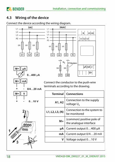
4.3 Wiring of the deviceConnect the device according the wiring diagram.
�
�
�
M+
µA mA V
Connect the conductor to the push-wire terminals according to the drawing.
Terminal Connections
A1, A2Connection to the supply voltage Us
L1, L2, L3, (N)Connection to the system to be monitored
M+(common) positive pole of the analogue interface
μA Current output 0…400 μA
mA Current output 0/4…20 mA
V Voltage output 0…10 V
18 VMD420-DM_D00227_01_M_XXEN/07.2015

Installation, connection and commissioning
4.4 Commissioning preset function/factory setting
Material damage by improper connection of the device! Priorto commissioning make sure that the device is properlyconnected!
After connecting a brand-new VMD420… to a standardsystem of Un = 400 V 50 Hz, the response values areautomatically set by the internal preset function:Overvoltage = 440 V (400 V + 10 %) (50 Hz + 1 Hz)Undervoltage = 340 V (400 V - 15 %) (50 Hz - 1 Hz)Other operating ranges of the preset function are given in thetechnical data "response values" and in the description of thefunction.
During the first start-up process the following responsevalues are automatically set related to Un:Response value: overvoltage (> U): 1.1 Un Response value: undervoltage (< U): 0.85 Un
CAUTION
19VMD420-DM_D00227_01_M_XXEN/07.2015
Installation, connection and commissioning
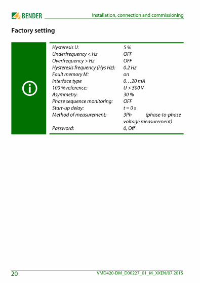
Factory setting
Hysteresis U:Underfrequency < HzOverfrequency > HzHysteresis frequency (Hys Hz):Fault memory M:Interface type100 % reference:Asymmetry:Phase sequence monitoring:Start-up delay:Method of measurement:
Password:
5 %OFFOFF0.2 Hzon0…20 mAU > 500 V30 %OFFt = 0 s3Ph (phase-to-phasevoltage measurement)0, Off
20 VMD420-DM_D00227_01_M_XXEN/07.2015
5. Operation and setting
5.1 Getting to know the user interface
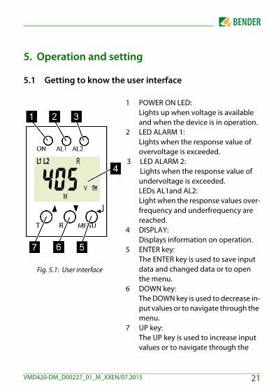
Fig. 5.1: User interface
1 POWER ON LED:Lights up when voltage is available and when the device is in operation.
2 LED ALARM 1:Lights when the response value of overvoltage is exceeded.
3 LED ALARM 2:Lights when the response value of undervoltage is exceeded.LEDs AL1and AL2:Light when the response values over-frequency and underfrequency are reached.
4 DISPLAY:Displays information on operation.
5 ENTER key:The ENTER key is used to save input data and changed data or to open the menu.
6 DOWN key:The DOWN key is used to decrease in-put values or to navigate through the menu.
7 UP key:The UP key is used to increase input values or to navigate through the
21VMD420-DM_D00227_01_M_XXEN/07.2015

Operation and setting
5.2 Understanding of standard display indications
Fig. 5.2: Standard displays1 DISPLAY LINE CONDUCTORS
L1-L3:Displays active line conduc-tors.
2 DISPLAY ASYMMETRY:Displays the asymmetry value as %.
3 DISPLAY NEUTRAL CONDUC-TOR:Neutral conductor is active.
4 DISPLAY PHASE SEQUENCE:R = clockwiseL = anticlockwise
5 DISPLAY AREA FOR UNITS:Displays the value of a unit.% = per cent (asymmetry and hysteresis) Hz = frequency in hertzs = secondsk = kiloV = volt
6 DISPLAY TYPE OF VOLTAGE:Displays the type of voltage.
7 PASSWORD PROTECTION EN-ABLED:Indicates that password pro-tection is activated.
8 FAULT MEMORY ACTIVATED:Indicates that the fault memo-ry is activated.
9 DISPLAY HYSTERESIS:Displays hysteresis as %.
10 DISPLAY VALUE:Displays values.
22 VMD420-DM_D00227_01_M_XXEN/07.2015

Operation and setting
5.3 Getting to know keys and key functionsThe following table shows the functions of the keys for navigation on the dis-play, navigation through the menu and parameter setting. From "Chapter 5.4 Querying values" onwards, only the respective key symbols are used for que-rying values.
Key Key symbol Function
UP
Call up the next display Move to the next menu, sub menu
or category Activate parameters Change the parameter value
(increase) Keep key pressed for more than 1.5
seconds: Carry out the manual self test.
DOWN
Call up the next display Move to the next menu, sub menu Deactivate parameters Change parameters (decrease) Keep key pressed for more than 1.5
seconds: Clear fault memory.
ENTER
Call up menu, submenu. Save changed parameter value. Keep key pressed for more than 1.5
seconds: Call up/leave the menu/move to the next higher submenu item.
23VMD420-DM_D00227_01_M_XXEN/07.2015

Operation and setting
5.4 Querying valuesBy default, the display shows the phase-to-phase voltage between L1 and L2. By pressing the UP and DOWN key, the phase-to-phase voltage between L1 and L3, L2 and L3 as well as asymmetry, system frequency and phase sequence can be queried
The flashing elements in the display indications below arehighlighted as grey-shaded fields.
Query Display indication
1. Query phase-to-phase voltage L1/L2
2. Change display indication
3. Query phase-to-phase voltage L2/L3
4. Change display indication
5. Query phase-to-phase voltage L1/L3
6. Change display indication
24 VMD420-DM_D00227_01_M_XXEN/07.2015

Operation and setting
5.5 Starting the self test manuallyThe self test described in "Chapter 3.2.2 Automatic self test" can also be start-ed manually. During the self test, internal functional faults are detected and are indicated as error codes on the display.In order to start the self test manually:
1. Keep the test button T (UP) pressed for more than 1.5 seconds.
7. Query asymmetry
8. Change display indication
9. Query system frequency
10. Change display indication
11. Query phase sequence
On the display the text “tes“ and all applicable displayelements will appear.
Query Display indication
25VMD420-DM_D00227_01_M_XXEN/07.2015

Operation and setting
5.6 Clearing the fault memoryThe device utilises an erasable fault memory. In order to clear the fault memory: Keep the UP key pressed for more than 1.5 seconds.
5.7 Calling up or leaving the menuIn order to call up the menu: Keep the ENTER key pressed for more than 1.5 seconds.For leaving the menu: Keep the ENTER key pressed again for more than 1.5 seconds.
5.8 Carrying out settings in the menu
5.8.1 Selecting menu itemsPress the ENTER key for more than 1.5 seconds to call up the menu. Menu items for different settings are available. Some menu items consist of several submenu items. The UP/DOWN keys can be used to navigate through the menu items. Keep the ENTER key pressed no longer than 1.5 seconds to call up the menu item. Keep the ENTER key pressed for more than 1.5 seconds to return to the next higher menu level.
Menu item/Key to call up
Description/parameter setting
Querying and setting response values: Undervoltage: < U (AL2) Overvoltage: > U (AL1) Hysteresis of the voltage response values: Hys U Asymmetry: Asy (AL1 and AL2) Underfrequency: < Hz (AL1 and AL2) Overfrequency: > Hz (AL1 and AL2) Hysteresis of the frequency response values: Hys Hz Phase sequence: PHS (AL1 and AL2)
26 VMD420-DM_D00227_01_M_XXEN/07.2015

Operation and setting
1. Press the UP/DOWN key to select the next menu item.
Configuring the fault memory and the analogue interface: Fault memory: activate/deactivate or select con
mode Selection of the type of the analogue interface:
0…400 μA, 0/4…20 mA, 0…10 V Determine 100 % reference related to the analogue
output signal (submenu AnA)
2. Press the UP/DOWN key to select the next menu item.
Setting the start-up delay t
3. Press the UP/DOWN key to select the next menu item.
Setting the parameters for device control Select method of measurement 3Ph or 3n Enable or disable password protection, change pass-
word Re-establish factory setting Start the preset function PrE manually. Service menu SyS blocked
4. Press the UP/DOWN key to select the next menu item.
Query hard and software version
5. Press the UP/DOWN key to select the next menu item.
Menu item/Key to call up
Description/parameter setting
27VMD420-DM_D00227_01_M_XXEN/07.2015

Operation and setting
5.8.2 Carrying out settings in the menu item AL1. Select menu item AL.2. Carry out parameter change as illustrated below.3. Keep the ENTER key pressed for more than 1.5 seconds to return to the
menu item level after parameter change.
Query stored alarm values
6. Press the UP/DOWN key to select the next menu item.
Move to the next higher menu level (return)
Menu item AL
Select submenu item
Activate/deacti-vate parameters
Change dis-play parame-ter value
Change/save param.
1. Set the response value for undervoltage
2. Select sub-menu item
Menu item/Key to call up
Description/parameter setting
28 VMD420-DM_D00227_01_M_XXEN/07.2015

Operation and setting
3. Set the response value for overvoltage
4. Select sub-menu item
5. Set the hys-teresis for voltage response val-ues
6. Select sub-menu item
7. Set the asym-metry response value
8. Select sub-menu item
Menu item AL
Select submenu item
Activate/deacti-vate parameters
Change dis-play parame-ter value
Change/save param.
29VMD420-DM_D00227_01_M_XXEN/07.2015

Operation and setting
9. Set the response value for underfre-quency
10. Select sub-menu item
11. Set the response value for overfre-quency
12. Select sub-menu item
13. Set the hys-teresis for fre-quency response value
14. Select sub-menu item
Menu item AL
Select submenu item
Activate/deacti-vate parameters
Change dis-play parame-ter value
Change/save param.
30 VMD420-DM_D00227_01_M_XXEN/07.2015

Operation and setting
15. Set the response value for phase sequence
16. Select sub-menu item
17. Return to menu item AL
Menu item AL
Select submenu item
Activate/deacti-vate parameters
Change dis-play parame-ter value
Change/save param.
31VMD420-DM_D00227_01_M_XXEN/07.2015
Operation and setting
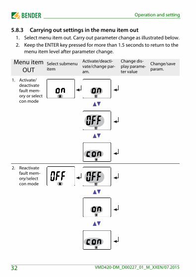
5.8.3 Carrying out settings in the menu item out1. Select menu item out. Carry out parameter change as illustrated below.2. Keep the ENTER key pressed for more than 1.5 seconds to return to the
menu item level after parameter change.
Menu item OUT
Select submenu item
Activate/deacti-vate/change par-am.
Change dis-play parame-ter value
Change/save param.
1. Activate/deactivate fault mem-ory or select con mode
2. Reactivate fault mem-ory/select con mode
32 VMD420-DM_D00227_01_M_XXEN/07.2015

Operation and setting
3. Select sub-menu item
4. Select cur-rent output0…20 mA
5. Change parameter
6. Select cur-rent output 0…400 μA
7. Change parameter
8. Select volt-age output 0…10 V
9. Change parameter
10. Select cur-rent output 4…20 mA
11. Select sub-menu item
Menu item OUT
Select submenu item
Activate/deacti-vate/change par-am.
Change dis-play parame-ter value
Change/save param.
33VMD420-DM_D00227_01_M_XXEN/07.2015

Operation and setting
12. Set the 100 % reference of the analogue output to:highest volt-age of all 3 phases
13. Change parameter
14. Set the 100 % reference to:voltage at L1
15. Activate parameter L1
The activation of L1 will result in deactivation of all other pa-rameters in the AnA submenu!
16. Set the value of parameter AL1
Select and activate the parameters L2, L3, Asy, Hz and PHS as illustrat-ed above.
17. Change parameter
Menu item OUT
Select submenu item
Activate/deacti-vate/change par-am.
Change dis-play parame-ter value
Change/save param.
34 VMD420-DM_D00227_01_M_XXEN/07.2015

Operation and setting
Page 13 provides a complete list of all selectable parameters for the analogue interface.
18. Set the 100 % reference to:response value over-voltage of all 3 phases
19. Activate parameter AL (L1 L2 L3)
The activation of AL (L1 L2 L3) will result in deactivation of all other parameters in the AnA submenu!
Select and activate the parameters L1, L2, L3 and Asy as illustrated above.
20. Change parameter
Menu item OUT
Select submenu item
Activate/deacti-vate/change par-am.
Change dis-play parame-ter value
Change/save param.
35VMD420-DM_D00227_01_M_XXEN/07.2015

Operation and setting
5.8.4 Carrying out settings in the menu item t1. Select menu item t2. Carry out parameter change as illustrated below.3. Keep the ENTER key pressed for more than 1.5 seconds to return to the
menu item level after parameter change.
Menu item t
Select submenu item
Activate/deacti-vate parameters
Change dis-play parame-ter value
Change/save param.
1. Set start-up delay for device start
2. Select sub-menu item
3. Return to menu item t
36 VMD420-DM_D00227_01_M_XXEN/07.2015

Operation and setting
5.8.5 Carrying out settings in the menu item SEt1. Select menu item SEt.2. Carry out parameter change as illustrated below.3. Keep the ENTER key pressed for more than 1.5 seconds to return to the
menu item level after parameter change.
Menu item SET
Select submenu item
Activate/deacti-vate/change par-am.
Change dis-play parame-ter value
Change/save param.
1. Set method of measure-ment for phase
2. Select sub-menu item
3. Enable pass-word protec-tion and enter pass-word (3-digit numerical code)
37VMD420-DM_D00227_01_M_XXEN/07.2015

Operation and setting
4. Changing the password
5. Disable pass-word protec-tion
6. Select sub-menu item
Menu item SET
Select submenu item
Activate/deacti-vate/change par-am.
Change dis-play parame-ter value
Change/save param.
38 VMD420-DM_D00227_01_M_XXEN/07.2015

Operation and setting
7. Re-establish factory set-ting
The text "run“ will appear on the display and the device will automatically reset to factory setting.
8. Select sub-menu item
9. Activate pre-set function for 3Ph and 3n manually.
The texts "run“ and “PrE“ will alternately appear on the display. If the text “rdY“ appears on the display, the preset function has been carried out for 3n resp. 3Ph.
Menu item SET
Select submenu item
Activate/deacti-vate/change par-am.
Change dis-play parame-ter value
Change/save param.
39VMD420-DM_D00227_01_M_XXEN/07.2015
Operation and setting
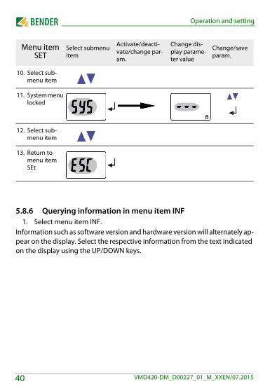
5.8.6 Querying information in menu item INF1. Select menu item INF.
Information such as software version and hardware version will alternately ap-pear on the display. Select the respective information from the text indicated on the display using the UP/DOWN keys.
10. Select sub-menu item
11. System menu locked
12. Select sub-menu item
13. Return to menu item SEt
Menu item SET
Select submenu item
Activate/deacti-vate/change par-am.
Change dis-play parame-ter value
Change/save param.
40 VMD420-DM_D00227_01_M_XXEN/07.2015

Operation and setting
5.8.7 Querying and clearing fault memory in the menu item HIS1. Select menu item HIS.2. Change parameters according to table.3. Keep the ENTER key pressed for more than 1.5 seconds to return to the
menu item level after parameter change.
Menu item HIS Fault indication /Submenu item
1. Query voltage faults L1/L2
2. Select fault indication
3. Query voltage faults L2/L3
4. Select fault indication
5. Query voltage faults L1/L3
6. Select fault indication
7. Query asymmetry faults
8. Select fault indication
41VMD420-DM_D00227_01_M_XXEN/07.2015

Operation and setting
9. Query frequency faults
10. Select fault indication
11. Query phase faults
12. Select fault indication
13. To clear the fault memory
14. Select fault indication
15. Return to menu item HiS
Menu item HIS Fault indication /Submenu item
42 VMD420-DM_D00227_01_M_XXEN/07.2015

6. Technical data
6.1 Data in tabular form( )* = factory setting
Insulation coordination acc. to IEC 60664-1 / IEC 60664-3Rated insulation voltage ....................................................................................................................................... 400 VRated impulse voltage/pollution degree ........................................................................................................... 4 kV / IIIProtective separation (reinforced insulation) between......................... (A1, A2) - (N, L1, L2, L3) - (M+, μA, mA, V)Voltage test acc. to IEC 61010-1:(N, L1, L2, L3) - (A1, A2), (M+, μA, mA, V) ..................................................................................................... 3.32 kV(N, L1, L2, L3) - (M+, μA, mA, V) ...................................................................................................................... 2.21 kV(A1, A2) - (M+, μA, mA, V) ............................................................................................................................... 2.21 kV
Supply voltageVMD420-DM-1:Supply voltage Us ......................................................................................................... AC 16…72 V / DC 9.6…94 VFrequency range Us ................................................................................................................................... 15…460 HzVMD420-DM-2:Supply voltage Us ............................................................................................................................. AC/DC 70…300 VFrequency range Us ................................................................................................................................... 15…460 HzPower consumption ............................................................................................................................................ ≤ 5 VA
Measuring circuitMeasuring range (r.m.s. value) (L-N) ..................................................................................................... AC 0…288 VMeasuring range (r.m.s. value) (L-L) ...................................................................................................... AC 0…500 VRated frequency fn .................................................................................................................................... 15…460 HzFrequency range ................................................................................................................................... 10…500 Hz**
Response valuesType of distribution system ...................................................................................................... 3(N) AC / 3 AC (3 AC)*Undervoltage < U (Alarm 2) (measurement method: 3Ph / 3n ) .................................. AC 6…500 V / 6…288 VOvervoltage > U (Alarm 1) (measuring method: 3Ph / 3n ) ......................................... AC 6…500 V / 6…288 VResolution of setting U ............................................................................................................................................... 1 V
43VMD420-DM_D00227_01_M_XXEN/07.2015

Technical data
Preset function for 3 AC measurement:Undervoltage< U (0.85 Un)* for Un = 400 V/ 208 V ............................................................................ 340 V / 177 VOvervoltage > U (1.1 Un)* for Un = 400 V/ 208 V .............................................................................. 440 V / 229 VPreset function for 3(N)AC measurement:Undervoltage < U (0.85 Un)* for Un = 230 V / 120 V .......................................................................... 196 V / 102 VOvervoltage > U (1.1 Un)* for Un = 230 V / 120 V .............................................................................. 253 V / 132 VHysteresis U ...................................................................................................................................... 1…40 % (5 %)*Asymmetry ...................................................................................................................................... 5…30 % (30 %)*Phase failure ...................................................................................................................... by setting of the asymmetryPhase sequence .............................................................................................. clockwise/ anticlockwise rotation (off)*Relative uncertainty: voltage at 50 Hz/60 Hz .................................................................................... ±1.5 %, ±2 digitRelative uncertainty: voltage in the range of 15 Hz…460 Hz ............................................................ ±3 %, ±2 digitUnderfrequency < Hz ........................................................................................................................... 10…500 Hz**Overfrequency > Hz .............................................................................................................................. 10…500 Hz**Resolution of setting f 10.0…99.9 Hz................................................................................................................ 0.1 HzResolution of setting f 100…500 Hz...................................................................................................................... 1 HzBy preset function:Underfrequency for fn = 16.7 Hz / 50 Hz / 60 Hz / 400 Hz ...................................... 15.7 Hz / 49 Hz / 59 Hz / 399 HzOverfrequency for fn = 16.7 Hz / 50 Hz / 60 Hz / 400 Hz ........................................ 17.7 Hz / 51 Hz / 61 Hz / 401 HzHysteresis frequency Hys Hz ....................................................................................................... 0.1…2 Hz (0.2 Hz)*Relative uncertainty: frequency in the range of 15…460 Hz .......................................................... ±0.2 %, ±1 digit
Specified timeStart-up delay ..................................................................................................................................... 0…300 s (0 s)*Resolution of setting t (0…10 s) .......................................................................................................................... 0.1 sResolution of setting t (10…99 s) ......................................................................................................................... 1 sResolution of setting t (100…300 s) ................................................................................................................... 10 sOperating time voltage tae ............................................................................................................................ ≤ 140 msOperating time frequency tae ......................................................................................................................... ≤ 335 msResponse time tan ............................................................................................................................................ tan = taeRecovery time tb ................................................................................................................................................. 300 ms
Displays, memoryDisplay ..................................................................................................... LC display, multi-functional, not illuminatedDisplay range, measured value................................................................................................................. AC 0…500 VOperating uncertainty: voltage at 50 Hz/60 Hz ................................................................................ ±1.5 %, ±2 digit
44 VMD420-DM_D00227_01_M_XXEN/07.2015

Technical data
Operating uncertainty: voltage in the range of 15…460 Hz .............................................................. ±3 %, ±2 digitOperating uncertainty: frequency in the range of 15…460 Hz ...................................................... ±0.2 %, ±1 digitHistory memory (HiS) for the first alarm value................................................................ data record measured valuesPassword ...................................................................................................................................... Off / 0…999 (OFF)*Fault memory (M) alarm relay ...................................................................................................... on / off / con (on)*
Analog outputVoltage output:Open circuit voltage (terminals open) .......................................................................................................... ≤ DC 20 VVoltage output ............................................................................................................................................ DC 0…10 VBurden ................................................................................................................................................................. ≥ 1 kΩCurrent outputs:Short-circuit current ........................................................................................................ ≤ 30 mA, short-circuit proofCurrent output ..................................................................................................................................... DC 0/4…20 mABurden ............................................................................................................................................................... ≤ 500 Ω Current output ...................................................................................................................................... DC 0…400 μABurden ............................................................................................................................................................ ≤ 12.5 kΩ
Environment/EMCEMC ............................................................................................................................................................. EN 61326-1Ambient temperatures:Operating temperature ........................................................................................................................... -25…+55 °CTransport ................................................................................................................................................. -25…+70 °CLong-term storage .................................................................................................................................. -25…+55 °CClassification of climatic conditions acc. to IEC 60721:Stationary use (IEC 60721-3-3) .............................................................. 3K5 (no condensation, no formation of ice)Transport (IEC 60721-3-2) ....................................................................................................................................... 2K3Long-term storage (IEC 60721-3-1) ........................................................................................................................ 1K4Classification of mechanical conditions acc. to IEC 60721:Stationary use (IEC 60721-3-3) ............................................................................................................................. 3M4Transport (IEC 60721-3-2) ..................................................................................................................................... 2M2Long-term storage (IEC 60721-3-1) ...................................................................................................................... 1M3
45VMD420-DM_D00227_01_M_XXEN/07.2015

Technical data
ConnectionConnection .................................................................................................................. screw-type terminalsConnection properties:Rigid/ flexible ............................................................................................. 0.2…4 / 0.2…2.5 mm2 / AWG 24…12Multi-conductor connection (2 conductors with the same cross section):Rigid, flexible....................................................................................................................... 0.2…1.5 / 0.2…1.5 mm2
Stripping length ............................................................................................................................................ 8…9 mmTightening torque .................................................................................................................................... 0.5…0.6 NmConnection .................................................................................................................... push-wire terminalsConnection properties:Rigid........................................................................................................................... 0.2…2.5 mm2 ( AWG 24…14)Flexible without ferrules ........................................................................................... 0.2…2.5 mm2 ( AWG 24…14)Flexible with ferrules................................................................................................. 0.2…1.5 mm2 ( AWG 24…16)Stripping length .................................................................................................................................................. 10 mmOpening force........................................................................................................................................................... 50 NTest opening, diameter....................................................................................................................................... 2.1 mm
General dataOperating mode ........................................................................................................................... continuous operationMounting ..................................................................................................................................................... any positionDegree of protection, internal components (IEC 60529)......................................................................................... IP30Degree of protection, terminals (IEC 60529) .......................................................................................................... IP20Enclosure material .................................................................................................................................... polycarbonateFlammability class ............................................................................................................................................UL94 V-0DIN rail mounting acc. to ............................................................................................................................... IEC 60715Screw fixing ......................................................................................................................... 2 x M4 with mounting clipSoftware version .......................................................................................................................................... D238 V2.2xWeight................................................................................................................................................................ ≤ 150 g( )* = factory setting** = The technical data only applies to the operating range of the rated frequency (15…460 Hz).
46 VMD420-DM_D00227_01_M_XXEN/07.2015
Technical data
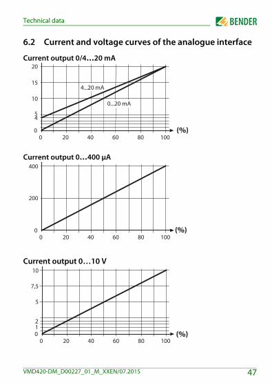
6.2 Current and voltage curves of the analogue interface
Current output 0/4…20 mA
Current output 0…400 μA
Current output 0…10 V
47VMD420-DM_D00227_01_M_XXEN/07.2015

Technical data
6.3 Standards, approvals and certifications
6.4 Ordering information
Device typeNominal voltage
Un*Supply voltage US* Art. No.
VMD420-DM-1(push-wire terminals)
3(N)AC 0…500 V/ 288 V
15…460 Hz
AC 16…72 V / DC 9.6 V…94 V
DC, 15…460 HzB 7301 0017
VMD420-DM-13(N)AC 0…500 V/
288 V15…460 Hz
AC 16…72 V / DC 9.6 V…94 V
DC, 15…460 HzB 9301 0017
VMD420-DM-2(push-wire terminals)
3(N)AC 0…500 V/ 288 V
15…460 Hz
AC/DC 70…300 VDC, 15…460 Hz
B 7301 0018
VMD420-DM-23(N)AC 0…500 V/
288 V15…460 Hz
AC/DC 70…300 VDC, 15…460 Hz
B 9301 0018
*Absolute values of the voltage range
Mounting clip for screw fixing (1 piece per device, accessories) B 9806 0008
48 VMD420-DM_D00227_01_M_XXEN/07.2015

INDEX
AAutomatic self test 11Ccurrently measured values
- asymmetry 24- phase sequence 24- phase-to-phase voltage 24- rated frequency 24
FFactory setting 12, 19Fast commissioning for Un = 400 V 15Fault memory in the operating mode on, off
or con 11Function 9Functional faults 11
GGetting 21
IInstallation and connection 15
KKey functions 23Keys 23
MManual self test 11, 25Menu item AL 28Menu item HIS 41Menu item INF 40Menu item OUT 32Menu item SET 37Menu item t 36Menu, call up 26Menu, leave 26Menu, settings 26Mounting clip for screw fixing 48
OOperating elements, function 21Operation and setting 21Ordering information 48
PPassword protection 12Preset function 10
QQuerying values 24
SSelecting menu items 26Standard display indications 22Start-up delay t 12
49VMD420-DM_D00227_01_M_XXEN/07.2015

TTechnical data 43To clear the fault memory 26
UUser interface 21
WWiring diagram 18Work activities on electrical installations 8
50 VMD420-DM_D00227_01_M_XXEN/07.2015


Bender GmbH & Co. KGLondorfer Str. 65 • 35305 Gruenberg • GermanyPostfach 1161 • 35301 Gruenberg • Germany
Tel.: +49 6401 807-0Fax: +49 6401 807-259
Email: [email protected]
Photos: Bender archives BENDER Group