Embed Size (px)
Citation preview
Daffodil International University i
Empirical Study on Network Architecture and Routing
Management of Interconnection Exchange (ICX) of Summit
Communications Limited
By
Md. Nahidul Islam
ID: 151-19-1734
This Internship Report is presented in partial fulfillment of the requirements of the Degree
of Bachelor of Science in Electronics and Telecommunication Engineering
Supervised By
Engr. Md. Zahirul Islam
Assistant Professor
Department of ICE
Daffodil International University
DAFFODIL INTERNATIONAL
UNIVERSITY DHAKA-1207, BANGLADESH
December, 2018

Daffodil International University ii

Daffodil International University iii
Daffodil International University iv
Daffodil International University v
ACKNOWLEDGMENTS
At First, I am like to convey my gratitude to the Almighty for charitable me the right path
while trying the duty.
The real sprit of achieving a goal is finished the way of quality and austere castigation. I
would have never thrived in effecting my task without the teamwork, help and support
provided to me by many personalities.
This internship report would not consume been possible without the provision and direction
of Engr. Md. Zahirul Islam, Assistant Professor, Department of Electronics and
Telecommunication Engineering, Daffodil International University, Dhaka, under whose
direction I chose this topic.
I would like to rapid my heartiest gratitude to Md. Taslim Arefin, Associate Professor and
Head, Department of Electronics and Telecommunication Engineering, for his kind help to
surface our thesis and also to other faculty participants, the staffs of the ETE Department of
Daffodil International University.
I must grant with due esteem the perpetual support and endurance of my family members for
final this internship.
Md. Nahidul Islam
Daffodil International University vi
Abstract
It was an incredible chance to work under Summit Communications Ltd. The primary reason for
the program was to see the genuine circumstance. The scholastic learning isn't all around ok to
contend with genuine world. This temporary position program was useful to confront the genuine
workplace. In Summit Communications Ltd. I have invested a decent energy in learning and was
compensated for my earnest attempts, figured out how to manage diverse circumstances, had
understanding of corporate workplace which influences a worker execution and frame of mind
towards work, had great time in learning and performing. I have likewise accumulated
involvement about the disturbance of the inconvenience times while touchstone was
experiencing one of its real progress stage. Certainty, on time basic leadership, consistency,
diligent work, cooperation, searching accomplishment out of dim, advancement, imagination,
hierarchical survival are the key learning's out of my activity and I might want to state that it will
be one of my best aptitude that would stay with me and help me in future which will offer
numerous difficulties. I might want to feature this, that my involvement with Summit
Communications Ltd was truly noteworthy and loaded with learning's, the place I found a ton of
positive changes in my mentality, learning and conduct.
Daffodil International University vii
TABLE OF CONTENT
Chapter Page
Chapter 1 1-2
1.1: Introduction 1
1.2: Company Profile 1
1.3 Objective of the Report 2
1.4 Summary of the Report 2
Chapter 2: Bangladesh Telecom Network Topology 3-5
2.1: Structure 3
2.2: Network topology 4
2.3: Interconnection Exchange (ICX) 4
Chapter 3: Transmission System 6-40
3.1. Transmission 6
3.1.2. Data transmission 7
3.1.2.2. TDM transmission 8
3.2. Capacity of Transmission 9
3.2.1. Features of STM-1 (Synchronous Transport Module level-1) 9
3.2.2. Features of STM-4 (Synchronous Transport Module-4) 9
3.2.3. Features of STM-16 (Synchronous Transport Module-16) 10
Daffodil International University viii
3.2.4. Features of STM-64 (Synchronous Transport Module) 10
3.2.5. E-1 11
3.3. Parameters of Data Transmission and TDM transmission 11
3.3.1. Physical Layer 12
3.3.2. Data-Link Layer 12
3.3.3. Presentation Layer 13
3.3.4. Physical Layer 13
3.3.5. Data-Link Layer 13
3.4. Technologies used in transmission 14
PDH 14
SDH 14
VPN 15
3.4.4. MPLS
15
3.4.5. VPLS
15
3.4.6. DWDM
16
3.4.7. WCDMA
16
3.5. Theory of Transmission
16
3.5.1. Multiplexing method
16
Daffodil International University ix
3.5.2. Advantages of SDH over PDH
18
3.5.3. Interface
18
Electrical interface
18
Optical interface
19
3.5.4. SDH Signal- STM-N Frame Structure
20
3.6. Transmission Media
20
3.6.1. Types of Transmission Media 21
3.6.2. Guided Transmission Media 21
3.6.2.1. Unshielded Twisted Pair wires
21
3.6.2.2. Coaxial Cable
21
3.6.2.3. Fiber Optic Cable
22
3.6.3. Advantages of optical fiber cabling compared to Unshielded Twisted Pair
(UTP)
23
3.6.4. Unguided Transmission Media 23
3.6.4.1. Microwaves Transmission
24
3.6.4.2. Radio waves Transmission
25
3.6.4.3. Infrared waves
25
3.6.4.4. Laser
26
3.7. Transmission Architecture
26
Daffodil International University x
GSM operation
27
3.8. Topology of Transmission 29
3.8.1. Ring Topology 29
3.8.2. Features of Ring Topology 29
3.8.3. Uses of Ring topology 30
3.8.4. MSP 30
3.8.5. SNCP 30
3.9. Transmission medium and capacity permitted by BTRC
31
3.9.1. 3G
32
3.9.2. LTE
32
3.10 Transmission in ICX
33
3.10.1. Call Flow Diagram 1 33
3.10.2. Call Flow Diagram 2 33
3.10.2.1. Domestic Call (incoming & outgoing) 34
3.10.2.2. International Call (incoming & outgoing) 35
3.10.3. Point of Interconnection (POI) 35
3.10.4. Summit Communications Limited. Switch Room 37
3.10.5. Point of Presence (POP) 38
Summit Communications Limited is associated with two POP 38
Daffodil International University xi
3.11 Transmission in IGW 39
Table- IGW Solution Product Model 40
CHAPTER (4): Geographical Device Interfaces 41-43
Geographical Device Interfaces 41
Chapter (5): Alarms 44-48
5. ALARM 44
5.1. R_LOS 44
The possible causes of the R_LOS alarm are as follows: 44
IF Board 45
5.2. R_LOF 45
Possible Causes: 45
5.3. AU_AIS 46
Possible Causes 46
5.4. HP_RDI 47
Possible Causes 47
5.5. IN_PWR_LOW 47
Possible Causes 48
Chapter (6): Conclusion 49
References 50
Daffodil International University xii
List of Figures
Figure Page
Fig 2.1: Basic structure of network topology. 3
Fig 2.2: Overall Architecture of ICX. 5
Fig 3.1: Basic Transmission System. 6
Fig 3.2: Data Transmission. 7
Fig 3.3: Packet Equipment Architecture. 8
Fig 3.4: TDM Equipment Architecture. 8
Fig 3.5: Power Transmission 8
Fig 3.6: STM-1 relates to a 64kbit/s channel. 9
Fig 3.7: STM-4 10
Fig 3.8: STM-16 10
Fig 3.9: STM-64 10
Fig 3.10: Add/drop 2 Mb/s signals from 140 Mb/s 17
Fig 3.11: STM-N Frame Structure 20
Fig 3.12: UTP Cable. 21
Fig 3.14: Fiber Optic Cable 22
Fig 3.16 : Radio Wave 25
Fig 3.15 : Microwave 24
Daffodil International University xiii
Fig 3.17: Infrared 25
Fig3.18 : Light Transmission 26
Fig 3.19: GSM System Architecture 27
Fig 3.20 : Ring Topology 29
Fig 3.21: MSP protection in SDH 30
Fig 3.22: SNCP protection in SDH 31
Fig 3.23: Call Flow Diagram 1. 33
Fig 3.24: Call Flow Diagram 2. 34
Fig 3.27: POI (Point Of Interconnection) 35
Fig 3.26: Summit Communications Limited Switch Room 37
Fig 3.27: Point of Presence (POP) Chittagong.
38
Fig 3.28: Point of Presence (POP) Khulna. 39
Figure 3.29: IGW Architecture 39
Fig 4.1: Summit Communications Limited Switch Room Mux 41
Fig 4.2: NRB POI 1 MUX 42
Fig 4.3: COLOASIA POI 2 (MUX) 42
Fig 4.4 Summit Communications Limited Chittagong POP 43
Fig 4.5: Summit Communications Limited Khulna POP 43
© Daffodil International University 1
Chapter1
Introduction
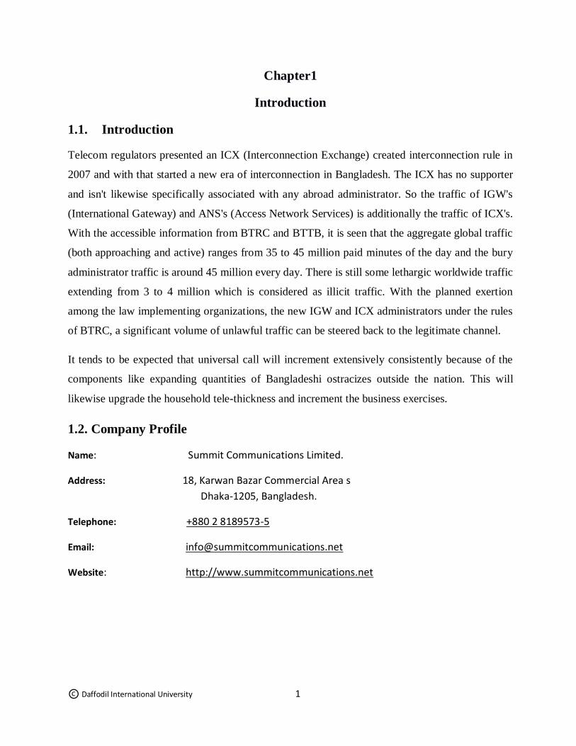
1.1. Introduction
Telecom regulators presented an ICX (Interconnection Exchange) created interconnection rule in
2007 and with that started a new era of interconnection in Bangladesh. The ICX has no supporter
and isn't likewise specifically associated with any abroad administrator. So the traffic of IGW's
(International Gateway) and ANS's (Access Network Services) is additionally the traffic of ICX's.
With the accessible information from BTRC and BTTB, it is seen that the aggregate global traffic
(both approaching and active) ranges from 35 to 45 million paid minutes of the day and the bury
administrator traffic is around 45 million every day. There is still some lethargic worldwide traffic
extending from 3 to 4 million which is considered as illicit traffic. With the planned exertion
among the law implementing organizations, the new IGW and ICX administrators under the rules
of BTRC, a significant volume of unlawful traffic can be steered back to the legitimate channel.
It tends to be expected that universal call will increment extensively consistently because of the
components like expanding quantities of Bangladeshi ostracizes outside the nation. This will
likewise upgrade the household tele-thickness and increment the business exercises.
1.2. Company Profile
Name: Summit Communications Limited.
Address: 18, Karwan Bazar Commercial Area s
Dhaka-1205, Bangladesh.
Telephone: +880 2 8189573-5
Email: [email protected]
Website: http://www.summitcommunications.net
© Daffodil International University 2
1.3 Objective of the Report
The main objectives of this report are as follows:
1. Cellular network: GSM System.
2. Types of cellular network technologies.
3. New BTS installation for 4G
1.4 Summary of the Report
The objective of this Internship is to improve an effective knowledge in of Broadcast & Earth
Station operation of Gazi Television Limited. In The First chapter, I have termed the Details &
objective an overall view that I am going to instrument during this internship work and I would
describe the background of sterlink Engineering Limited. company EHS rule.
The Second Chapter, Cellular System and GSM Technology
The Third chapter is describing, Cellular network generation
The last one is Chapter Four that is BTS installation for 4G and
Chapter five Conclusion.
© Daffodil International University 3
Chapter 2
Bangladesh Telecom Network Topologies
2.1. Structure:
As characterize in the National Telecommunication Policy 1998 and universal Long-Distance
Telecommunication Service (ILDTS) Policy 2007, every single versatile administrator is to
interconnect through Interconnection Exchange (ICX) and worldwide calls to be taken care of by
International Gateway (IGW) which is to be associated with the portable and settled
administrators through the ICXs.
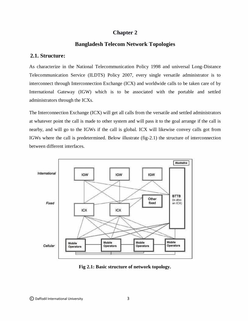
The Interconnection Exchange (ICX) will get all calls from the versatile and settled administrators
at whatever point the call is made to other system and will pass it to the goal arrange if the call is
nearby, and will go to the IGWs if the call is global. ICX will likewise convey calls got from
IGWs where the call is predetermined. Below illustrate (fig-2.1) the structure of interconnection
between different interfaces.
Fig 2.1: Basic structure of network topology.
© Daffodil International University 4
2.2 Network topology:
System design will be founded on three layers with proper gear and innovations subject to change
as and when required.
•The first layer is IGWs, which will be associated with International Long Distance Cable (ILDC)
systems and ICX. IGWs will have satellite earth station or VSAT as reinforcement until option
ILDC is accessible.
•The second layer is the ICX, which will be associated with IGWs and access organize benefit
(ANS) administrators. IPTSPs will be associated with NIX for bury IPTSP for local voice traffic.
Global and entomb administrators local voice traffic will be steered through ICXs.
•The third Layer is the ANS administrators who give benefits through end clients
straightforwardly. This layer is to guarantee the network between the ICX/NIX and the
supporters.
2.3 Interconnection Exchange (ICX):
"Interconnection Exchange (ICX)" is the exchanging framework which gives interconnection
among media transmission systems of administrators and permits checking, legitimate
interference (LI) offices and wandering number compactness. The quantity of ICX administrators
will be controlled by the legislature according to prerequisite of the media transmission area of
Bangladesh.
•Location of the ICXs will essentially be at Dhaka. More ICX will be setup in different areas
relying upon traffic volume and to enable increasingly country individuals to be associated with
the system as and when required.
•ICXs will have essential spine availability towards worldwide systems through ILDC organize.
•IGWs will have physical association with ICXs. ICXs will create and keep up interconnection
offices to associate the IGWs to ICXs and ICXs to ANS administrators through their POPs.
© Daffodil International University 5
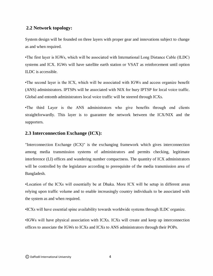
Fig 2.2: Overall Architecture of ICX.
© Daffodil International University 6
Chapter 3
Transmission System Definition of transmission in all aspects
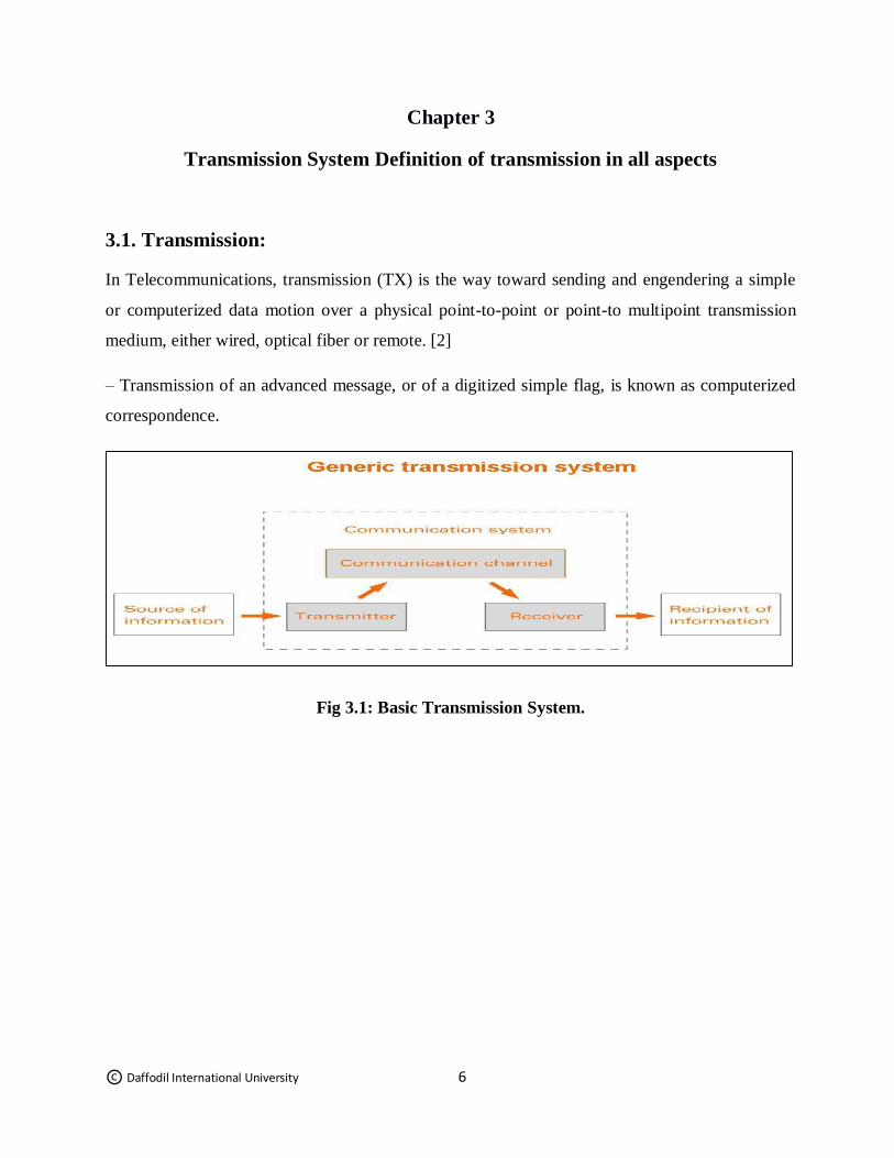
3.1. Transmission:
In Telecommunications, transmission (TX) is the way toward sending and engendering a simple
or computerized data motion over a physical point-to-point or point-to multipoint transmission
medium, either wired, optical fiber or remote. [2]
– Transmission of an advanced message, or of a digitized simple flag, is known as computerized
correspondence.
Fig 3.1: Basic Transmission System.
© Daffodil International University 7
In electrical engineering, there are deals with two types of transmission:
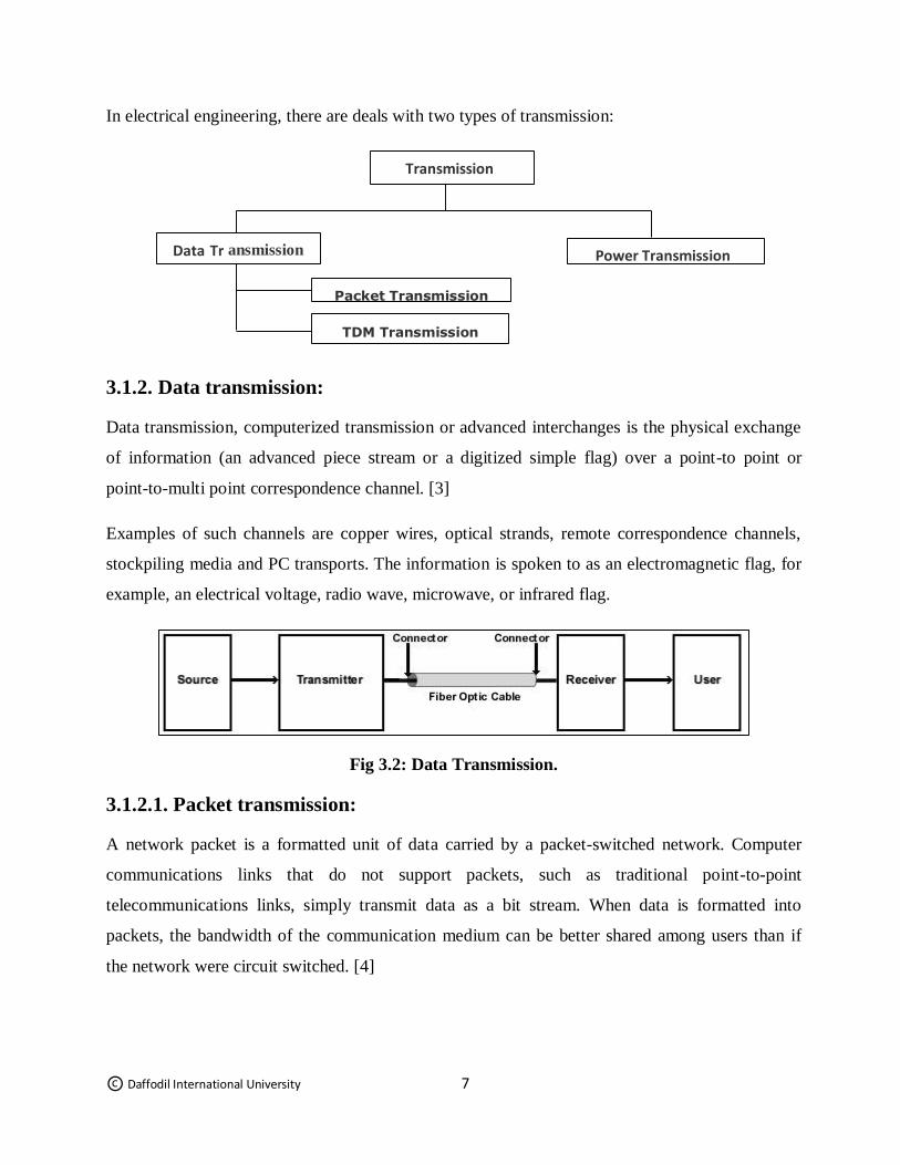
3.1.2. Data transmission:
Data transmission, computerized transmission or advanced interchanges is the physical exchange
of information (an advanced piece stream or a digitized simple flag) over a point-to point or
point-to-multi point correspondence channel. [3]
Examples of such channels are copper wires, optical strands, remote correspondence channels,
stockpiling media and PC transports. The information is spoken to as an electromagnetic flag, for
example, an electrical voltage, radio wave, microwave, or infrared flag.
Fig 3.2: Data Transmission.
3.1.2.1. Packet transmission:
A network packet is a formatted unit of data carried by a packet-switched network. Computer
communications links that do not support packets, such as traditional point-to-point
telecommunications links, simply transmit data as a bit stream. When data is formatted into
packets, the bandwidth of the communication medium can be better shared among users than if
the network were circuit switched. [4]
Transmission
Power Transmission Data Tr ansmission
Packet Transmission
TDM Transmission
© Daffodil International University 8
Fig 3.3: Packet Equipment Architecture.
3.1.2.2. TDM transmission:
Time-division multiplexing (TDM) is a strategy for putting numerous information streams in a
solitary flag by isolating the flag into numerous sections, each having a brief term. Every
individual information stream is reassembled at the less than desirable end dependent on the
planning. [5]
Fig 3.4: TDM Equipment Architecture.
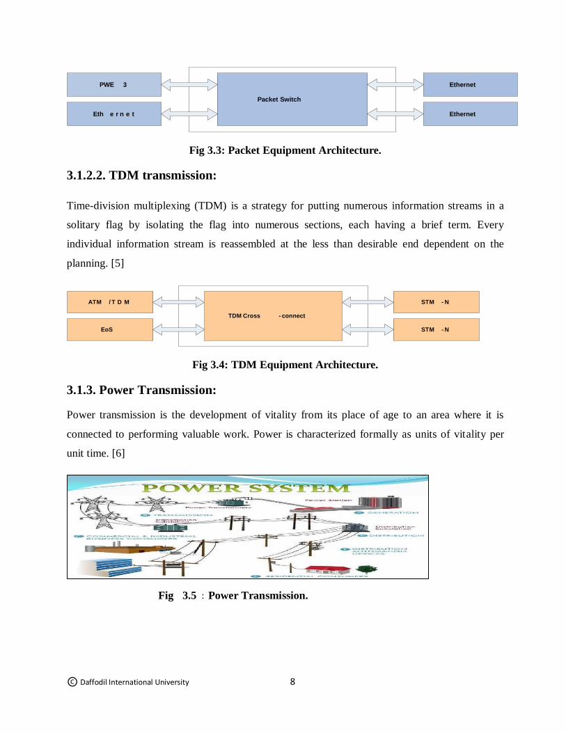
3.1.3. Power Transmission:
Power transmission is the development of vitality from its place of age to an area where it is
connected to performing valuable work. Power is characterized formally as units of vitality per
unit time. [6]
Fig 3.5 : Power Transmission.
STM - N
STM - N
EoS
ATM / T D M
TDM Cross - connect
Ethernet
Ethernet
Eth e r n e t
PWE 3
Packet Switch
© Daffodil International University 9
3.2. Capacity of Transmission:
The transmission limit depends on a recipe portraying the power between a transmitter and a
recipient. The proportion of these two numbers and the equation portrays the limit of the channel.
A channel has a specific limit with regards to transmitting data, regularly estimated by its
transmission capacity in Hz or its information rate in bits every second.
The different types of channel capacity distributed in transmission system. Those are:
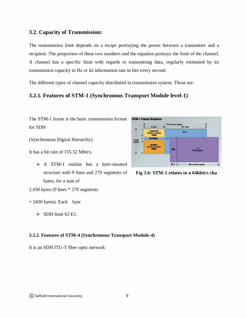
3.2.1. Features of STM-1 (Synchronous Transport Module level-1)
The STM-1 frame is the basic transmission format
for SDH
(Synchronous Digital Hierarchy).
It has a bit rate of 155.52 Mbit/s.
A STM-1 outline has a byte-situated
structure with 9 lines and 270 segments of
bytes, for a sum of
2,430 bytes (9 lines * 270 segments
= 2430 bytes). Each byte
SDH limit 63 E1.
3.2.2. Features of STM-4 (Synchronous Transport Module-4)
It is an SDH ITU-T fiber optic network
Fig 3.6: STM-1 relates to a 64kbit/s cha
© Daffodil International University 10
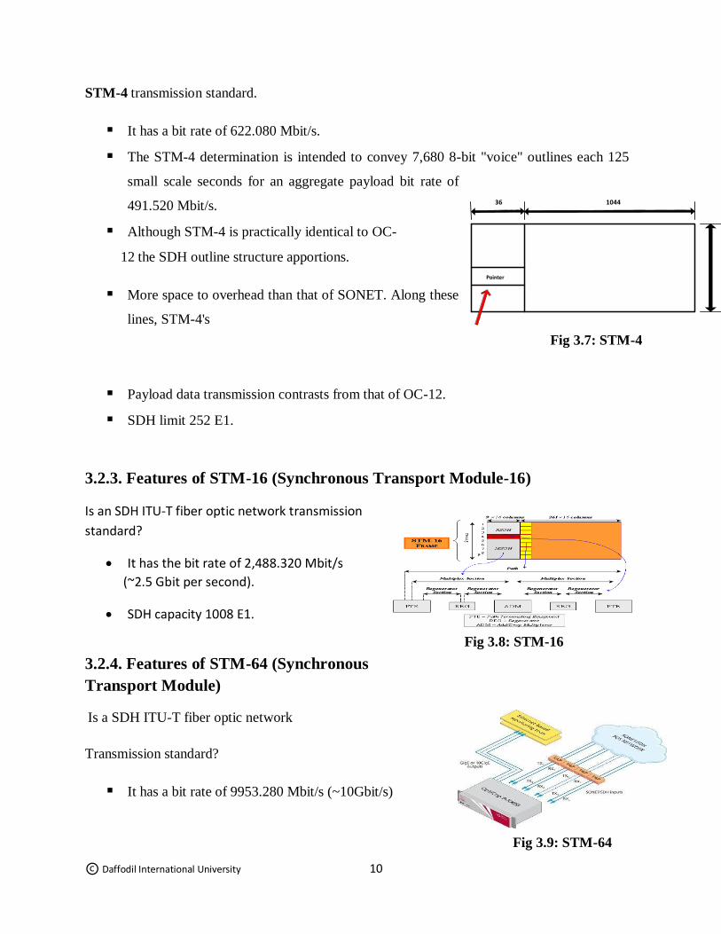
STM-4 transmission standard.
It has a bit rate of 622.080 Mbit/s.
The STM-4 determination is intended to convey 7,680 8-bit "voice" outlines each 125
small scale seconds for an aggregate payload bit rate of
491.520 Mbit/s.
Although STM-4 is practically identical to OC-
12 the SDH outline structure apportions.
More space to overhead than that of SONET. Along these
lines, STM-4's
Payload data transmission contrasts from that of OC-12.
SDH limit 252 E1.
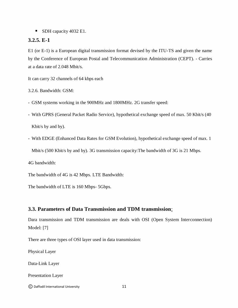
3.2.3. Features of STM-16 (Synchronous Transport Module-16)
Is an SDH ITU-T fiber optic network transmission
standard?
It has the bit rate of 2,488.320 Mbit/s
(~2.5 Gbit per second).
SDH capacity 1008 E1.
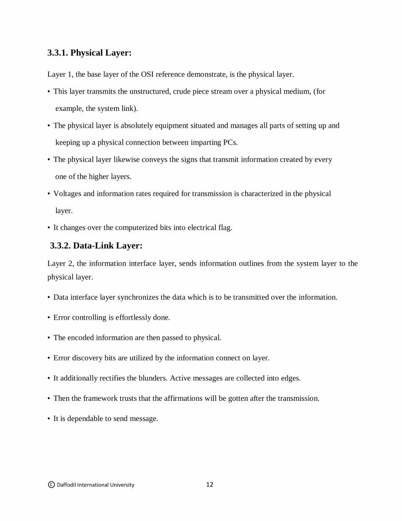
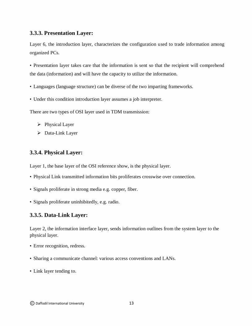
3.2.4. Features of STM-64 (Synchronous
Transport Module)
Is a SDH ITU-T fiber optic network
Transmission standard?
It has a bit rate of 9953.280 Mbit/s (~10Gbit/s)
36 1044
Pointer
Fig 3.7: STM-4
Fig 3.8: STM-16
Fig 3.9: STM-64
© Daffodil International University 11
SDH capacity 4032 E1.
3.2.5. E-1
E1 (or E-1) is a European digital transmission format devised by the ITU-TS and given the name
by the Conference of European Postal and Telecommunication Administration (CEPT). - Carries
at a data rate of 2.048 Mbit/s.
It can carry 32 channels of 64 kbps each
3.2.6. Bandwidth: GSM:
- GSM systems working in the 900MHz and 1800MHz. 2G transfer speed:
- With GPRS (General Packet Radio Service), hypothetical exchange speed of max. 50 Kbit/s (40
Kbit/s by and by).
- With EDGE (Enhanced Data Rates for GSM Evolution), hypothetical exchange speed of max. 1
Mbit/s (500 Kbit/s by and by). 3G transmission capacity:The bandwidth of 3G is 21 Mbps.
4G bandwidth:
The bandwidth of 4G is 42 Mbps. LTE Bandwidth:
The bandwidth of LTE is 160 Mbps- 5Gbps.
3.3. Parameters of Data Transmission and TDM transmission:
Dara transmission and TDM transmission are deals with OSI (Open System Interconnection)
Model: [7]
There are three types of OSI layer used in data transmission:
Physical Layer
Data-Link Layer
Presentation Layer
© Daffodil International University 12
3.3.1. Physical Layer:
Layer 1, the base layer of the OSI reference demonstrate, is the physical layer.
• This layer transmits the unstructured, crude piece stream over a physical medium, (for
example, the system link).
• The physical layer is absolutely equipment situated and manages all parts of setting up and
keeping up a physical connection between imparting PCs.
• The physical layer likewise conveys the signs that transmit information created by every
one of the higher layers.
• Voltages and information rates required for transmission is characterized in the physical
layer.
• It changes over the computerized bits into electrical flag.
3.3.2. Data-Link Layer:
Layer 2, the information interface layer, sends information outlines from the system layer to the
physical layer.
• Data interface layer synchronizes the data which is to be transmitted over the information.
• Error controlling is effortlessly done.
• The encoded information are then passed to physical.
• Error discovery bits are utilized by the information connect on layer.
• It additionally rectifies the blunders. Active messages are collected into edges.
• Then the framework trusts that the affirmations will be gotten after the transmission.
• It is dependable to send message.
© Daffodil International University 13
3.3.3. Presentation Layer:
Layer 6, the introduction layer, characterizes the configuration used to trade information among
organized PCs.
• Presentation layer takes care that the information is sent so that the recipient will comprehend
the data (information) and will have the capacity to utilize the information.
• Languages (language structure) can be diverse of the two imparting frameworks.
• Under this condition introduction layer assumes a job interpreter.
There are two types of OSI layer used in TDM transmission:
Physical Layer
Data-Link Layer
3.3.4. Physical Layer:
Layer 1, the base layer of the OSI reference show, is the physical layer.
• Physical Link transmitted information bits proliferates crosswise over connection.
• Signals proliferate in strong media e.g. copper, fiber.
• Signals proliferate uninhibitedly, e.g. radio.
3.3.5. Data-Link Layer:
Layer 2, the information interface layer, sends information outlines from the system layer to the
physical layer.
• Error recognition, redress.
• Sharing a communicate channel: various access conventions and LANs.
• Link layer tending to.
© Daffodil International University 14
3.4. Technologies used in transmission:
There are different types technology used in transmission and those are-
PDH:
The term plesiochronous signifies "almost synchronous" or a call that must be separated from
more than one transmission outline. The plesiochronous computerized progression (PDH) is a
broadcast communications organize transmission innovation intended for the vehicle of vast
information volumes crosswise over substantial scale advanced systems. The PDH configuration
permits the spilling of information without having isochronous (times running at indistinguishable
occasions, splendidly synchronized) to synchronize the flag trades. PDH tickers are running close,
yet not actually in time with each other so while multiplexing, flag landing times may vary as the
transmission rates are straightforwardly connected to the clock rate.
PDH underpins an information transmission rate of 2048 Kbps. The information rate is controlled
by a check in the gadget that creates the information. [8]
SDH:
In computerized phone transmission, "synchronous" signifies the bits from one call are conveyed
inside one transmission outline. Synchronous Optical Networking (SONET) and Synchronous
Digital Hierarchy (SDH) are institutionalized conventions that exchange different advanced piece
streams synchronously over optical fiber utilizing lasers or exceptionally intelligible light from
light-emanating diodes (LEDs). At low transmission rates information can likewise be exchanged
through an electrical interface. The strategy was created to supplant the Plesiochronous Digital
Hierarchy (PDH) framework for transporting a lot of phone brings and information traffic over a
similar fiber without synchronization issues.
SDH utilizes the accompanying Synchronous Transport Modules (STM) and rates: STM-1 (155
megabits for each second), STM-4 (622 Mbps), STM-16 (2.5 gigabits every second), and STM-64
(10Gbps). [9]
© Daffodil International University 15
VPN:
A Virtual Private Network (VPN) is a system innovation that makes a protected system
association over an open system, for example, the Internet or a private system possessed by a
specialist organization. Expansive organizations, instructive establishments, and government
offices use VPN innovation to empower remote clients to safely associate with a private system.
A VPN can associate different destinations over an expansive separation simply like a Wide Area
Network (WAN). VPNs are frequently used to stretch out intranets worldwide to scatter data and
news to a wide client base.
There are various VPN conventions being used that safe the vehicle of information traffic over an
open system foundation. Every convention shifts somewhat in how information is kept secure.
[10]
3.4.4. MPLS:
Multiprotocol Label Switching (MPLS) is a component in superior media communications
organizes that guide’s information starting with one system hub then onto the next dependent on
short way marks instead of long system addresses, keeping away from complex queries in a
directing table. The marks distinguish virtual connections (ways) between inaccessible hubs as
opposed to endpoints. MPLS can typify parcels of different system conventions. MPLS underpins
a scope of access innovations, including T1/E1, ATM, Frame Relay, and DSL. [11]
3.4.5. VPLS:
Virtual Private LAN Service (VPLS) is an approach to give Ethernet-based multipoint to
multipoint correspondence over IP or MPLS systems. It enables geologically scattered
destinations to share an Ethernet communicate space by interfacing locales through pseudo-wires.
The term 'locales' incorporates multiplicities of the two servers and customers. The innovations
that can be utilized as pseudo-wire can be Ethernet over MPLS. [12]
© Daffodil International University 16
3.4.6. DWDM:
Thick wavelength division multiplexing (DWDM) is an innovation that puts information from
various sources together on an optical fiber, with each flag conveyed in the meantime without
anyone else separate light wavelength. Utilizing DWDM, up to 80 (and hypothetically
progressively) separate wavelengths or channels of information can be multiplexed into a light-
stream transmitted on a solitary optical fiber. Each channel conveys a period division multiplexed
(TDM) flag. In a framework with each channel conveying 2.5 Gbps (billion bits for every
second), up to 200 billion bits can be conveyed a second by the optical fiber. DWDM is
additionally once in a while called wave division multiplexing (WDM).A key favorable position
to DWDM is that it's convention and bit-rate-autonomous. [13]
3.4.7. WCDMA:
W-CDMA (Wideband Code-Division Multiple Access), an ITU standard got from Code-Division
Multiple Access (CDMA), is formally known as IMT-2000 direct spread. W-CDMA is a third-
age (3G) versatile remote innovation that guarantees a lot higher information paces to versatile
and convenient remote gadgets than generally offered in the present market. W-CDMA can
bolster versatile/convenient voice, pictures, information, and video interchanges at up to 2 Mbps
(neighborhood) or 384 Kbps (wide territory get to). The information signals are digitized and
transmitted in coded, spread-range mode over an expansive scope of frequencies. A 5 MHz-wide
bearer is utilized, contrasted and 200 KHz-wide transporter for narrowband CDMA. [14]
3.5. Theory of Transmission:
3.5.1. Multiplexing method
In the present PDH framework, just 1.5Mb/s rate signals (counting Japanese Series 6.3Mb/s rate
flag) are synchronous. Every other flag are nonconcurrent and require code rate for legitimization
for coordinating and tolerating clock distinction. As PDH receives offbeat multiplexing strategy,
the area of the low rate signals are not standard nor settled when they are multiplexed into higher-
rate signals. In other words, the area of the lower signals can't be recognized from the higher
speed signals. Be that as it may, this is the way to straightforwardly include/drop bring down
speed signals from the higher speed signals. This is a similar when searching for an outsider in a
© Daffodil International University 17
group. You can without much of a stretch discover him on the off chance that you realize which
line and which push he remains in which swarm is masterminded in an explicit request. Be that as
it may, if the group is wrecked, you need to contrast every individual with the photograph with
find the man.
Since PDH embraces no concurrent multiplexing strategy, low-rate signals can't be specifically
included/dropped from PDH high-rate signals. For instance, 2Mb/s signals can't be
straightforwardly included/dropped from 140Mb/s signals. Here emerge two issues:
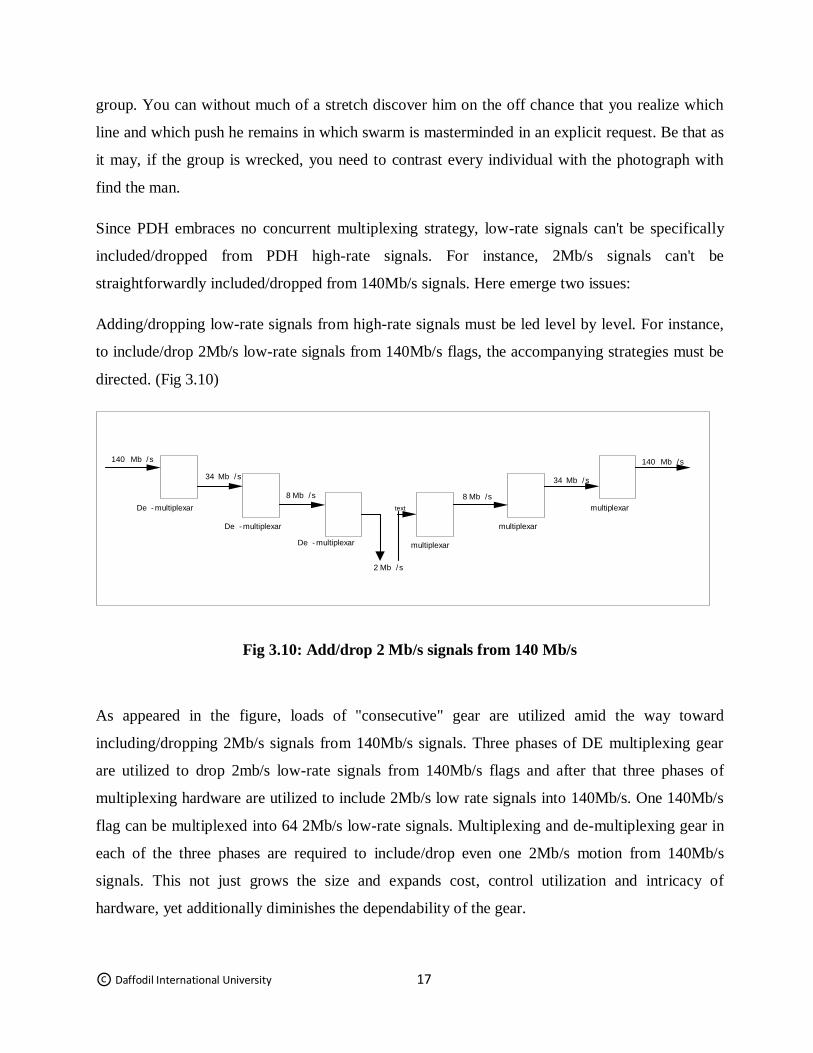
Adding/dropping low-rate signals from high-rate signals must be led level by level. For instance,
to include/drop 2Mb/s low-rate signals from 140Mb/s flags, the accompanying strategies must be
directed. (Fig 3.10)
Fig 3.10: Add/drop 2 Mb/s signals from 140 Mb/s
As appeared in the figure, loads of "consecutive" gear are utilized amid the way toward
including/dropping 2Mb/s signals from 140Mb/s signals. Three phases of DE multiplexing gear
are utilized to drop 2mb/s low-rate signals from 140Mb/s flags and after that three phases of
multiplexing hardware are utilized to include 2Mb/s low rate signals into 140Mb/s. One 140Mb/s
flag can be multiplexed into 64 2Mb/s low-rate signals. Multiplexing and de-multiplexing gear in
each of the three phases are required to include/drop even one 2Mb/s motion from 140Mb/s
signals. This not just grows the size and expands cost, control utilization and intricacy of
hardware, yet additionally diminishes the dependability of the gear.
140 Mb / s 140 Mb / s 34 Mb / s
34 Mb / s 8 Mb / s 8 Mb / s
2 Mb / s
De - multiplexar
De - multiplexar De - multiplexar
multiplexar
multiplexar
multiplexar
text
© Daffodil International University 18
Since including/dropping low-rate signs to high-rate ones must experience numerous phases of
multiplexing and de-multiplexing, impedance to the signs amid multiplexing/de-multiplexing
procedure will increment and transmission execution will disintegrate. This is agonizing in vast
limit transmission. That is the motivation behind why the transmission rate of PDH framework
has not being enhanced further.
3.5.2. Advantages of SDH over PDH
Since SDH transmission framework develops from PDH, it has unparalleled favorable
circumstances over PDH. Contrasted and PDH, it is another transmission framework that has
radical insurgency in specialized framework.
To start with, we will talk about the essential idea of SDH. The center of this idea is, in
perspective of an incorporated national media transmission system and worldwide
intercommunication, to set up computerized telecom systems, and to make up essential parts of
coordinated administrations advanced systems (ISDN), particularly broadband incorporated
administrations computerized systems (B-ISDN). Not quite the same as customary PDH, the
system dependent on SDH framework is a high uniform, institutionalized and astute system. It
utilizes widespread interfaces to accomplish similarity with various hardware from various
merchants. It is additionally gloats of profoundly proficient and facilitated the executives and
activity all through the entire system and transmission process, adaptable system and traffic
dispatching, and arrange self-recuperating capacity. It incredibly upgrades the usage proportion of
system assets the OAM costs because of the improved upkeep work.
Presently give the benefit of SDH (they can be viewed as the highlights of SDH) in a few
viewpoints.
3.5.3. Interface
Electrical interface:
Institutionalization of interfaces decides the likelihood of interconnection among various
hardware from various sellers.
© Daffodil International University 19
SDH framework gives a lot of standard data structure levels, i.e. a lot of standard of rate levels.
The fundamental flag transmission structure is a synchronous exchange module - STM-1 at a rate
of 155Mb/s. Computerized flag chains of importance of more elevated amounts, for example,
622Mb/s (STM-4) and 2.5Gb/s (STM-16) can be shaped by low-rate data modules (e.g. STM-
1)via byte interleaved multiplexing. The quantity of modules to be increased is a different of 4.
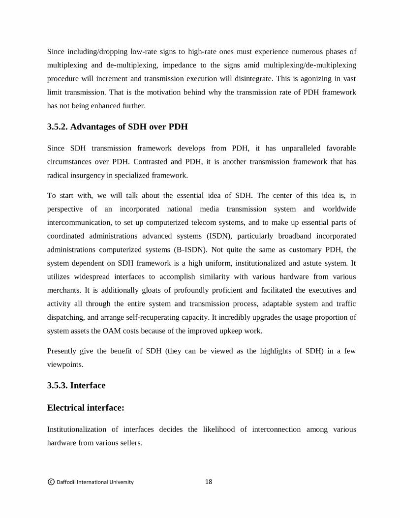
For instance, STM-4=4xSTM-1and STM-16=4xSTM-4. Byte interleaved multiplexing strategy: It
can be clarify by following model. There are three signs with the casing structure of 3 bytes in
each edge.
A B C
A1 A2 A3 B1 B2 B3 C1 C2 C3
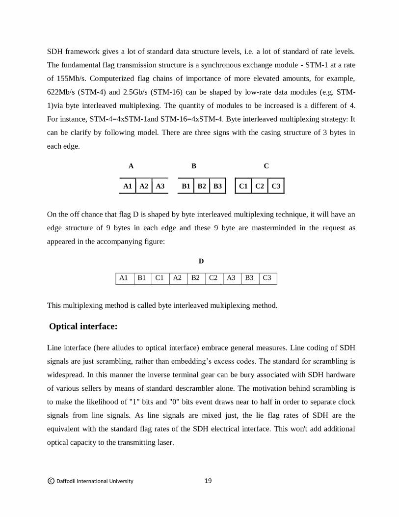
On the off chance that flag D is shaped by byte interleaved multiplexing technique, it will have an
edge structure of 9 bytes in each edge and these 9 byte are masterminded in the request as
appeared in the accompanying figure:
D
A1 B1 C1 A2 B2 C2 A3 B3 C3
This multiplexing method is called byte interleaved multiplexing method.
Optical interface:
Line interface (here alludes to optical interface) embrace general measures. Line coding of SDH
signals are just scrambling, rather than embedding’s excess codes. The standard for scrambling is
widespread. In this manner the inverse terminal gear can be bury associated with SDH hardware
of various sellers by means of standard descrambler alone. The motivation behind scrambling is
to make the likelihood of "1" bits and "0" bits event draws near to half in order to separate clock
signals from line signals. As line signals are mixed just, the lie flag rates of SDH are the
equivalent with the standard flag rates of the SDH electrical interface. This won't add additional
optical capacity to the transmitting laser.
© Daffodil International University 20
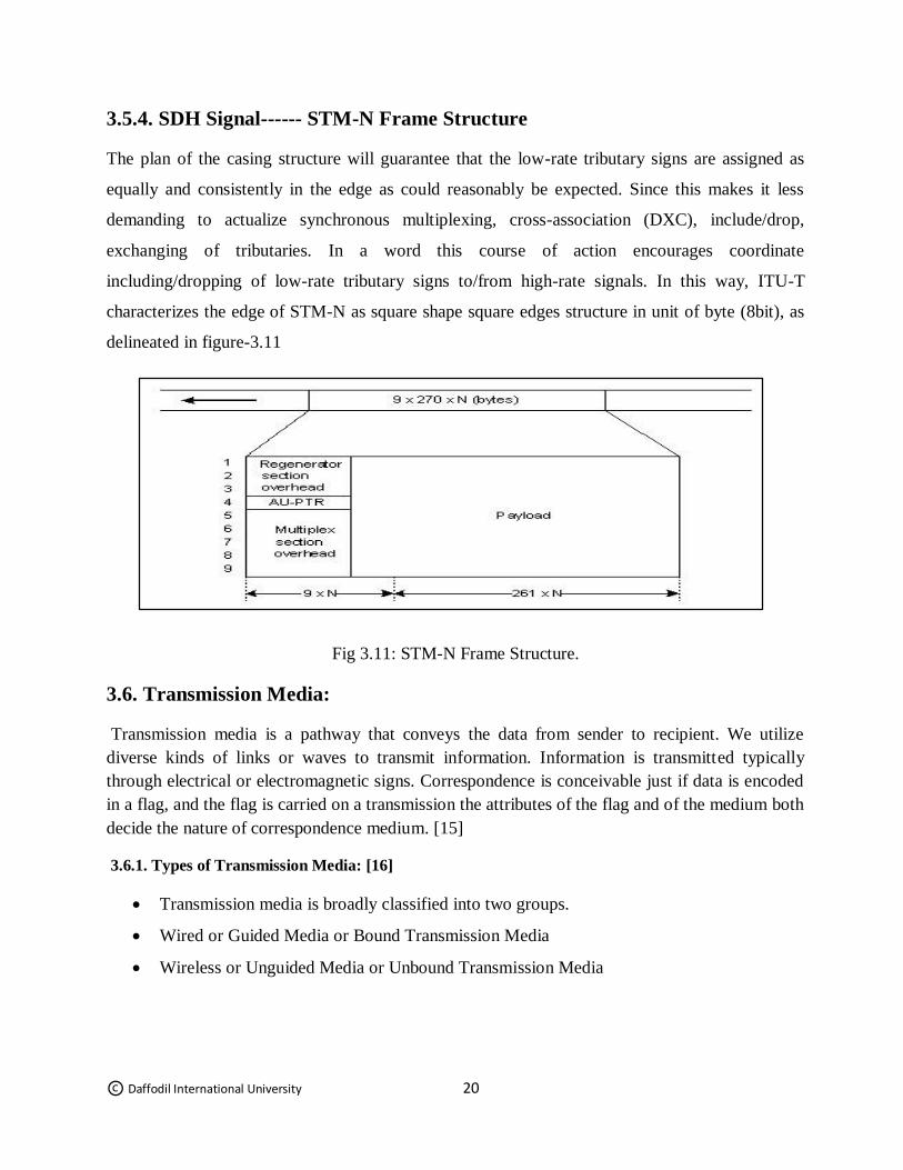
3.5.4. SDH Signal------ STM-N Frame Structure
The plan of the casing structure will guarantee that the low-rate tributary signs are assigned as
equally and consistently in the edge as could reasonably be expected. Since this makes it less
demanding to actualize synchronous multiplexing, cross-association (DXC), include/drop,
exchanging of tributaries. In a word this course of action encourages coordinate
including/dropping of low-rate tributary signs to/from high-rate signals. In this way, ITU-T
characterizes the edge of STM-N as square shape square edges structure in unit of byte (8bit), as
delineated in figure-3.11
Fig 3.11: STM-N Frame Structure.
3.6. Transmission Media:
Transmission media is a pathway that conveys the data from sender to recipient. We utilize
diverse kinds of links or waves to transmit information. Information is transmitted typically
through electrical or electromagnetic signs. Correspondence is conceivable just if data is encoded
in a flag, and the flag is carried on a transmission the attributes of the flag and of the medium both
decide the nature of correspondence medium. [15]
3.6.1. Types of Transmission Media: [16]
Transmission media is broadly classified into two groups.
Wired or Guided Media or Bound Transmission Media
Wireless or Unguided Media or Unbound Transmission Media
© Daffodil International University 21
3.6.2. Guided Transmission Media:
• Guided transmission media incorporates everything that 'directs' the transmission. That generally
appears as a type of a wire. Normally copper, yet can likewise be an optical fiber.
• Transmission limit relies upon the separation and on whether the medium is point-to-point or
multipoint.
•Examples:
1. Unshielded Twisted Pair wires o Coaxial Cable
2. Optical Fiber
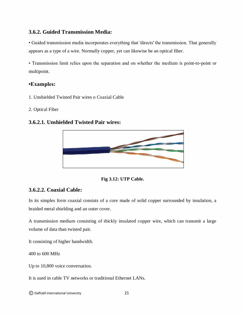
3.6.2.1. Unshielded Twisted Pair wires:
Fig 3.12: UTP Cable.
3.6.2.2. Coaxial Cable:
In its simples form coaxial consists of a core made of solid copper surrounded by insulation, a
braided metal shielding and an outer cover.
A transmission medium consisting of thickly insulated copper wire, which can transmit a large
volume of data than twisted pair.
It consisting of higher bandwidth.
400 to 600 MHz
Up to 10,800 voice conversation.
It is used in cable TV networks or traditional Ethernet LANs.
© Daffodil International University 22
Fig 3.13: Coaxial Cable
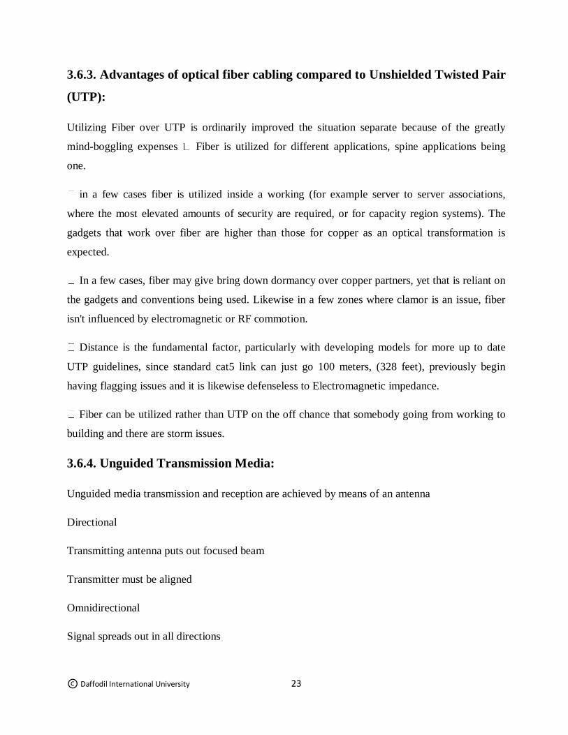
3.6.2.3. Fiber Optic Cable:
• An optical fiber (or optical fiber) is an adaptable, straightforward fiber made by illustration glass
(silica) or plastic to a distance across marginally thicker than that of a human hair.
• It is moderately new transmission medium utilized by phone organizations instead of long-
remove trunk lines.
• It is likewise utilized by privately owned businesses in actualizing neighborhood information
correspondence systems.
• In most systems fiber-optic link is utilized as the fast spine.
• Single-mode filaments are utilized for most correspondence interfaces longer than 1,000 meters
(3,300 ft.).
Fig 3.14: Fiber Optic Cable
© Daffodil International University 23
3.6.3. Advantages of optical fiber cabling compared to Unshielded Twisted Pair
(UTP):
Utilizing Fiber over UTP is ordinarily improved the situation separate because of the greatly
mind-boggling expenses Fiber is utilized for different applications, spine applications being
one.
in a few cases fiber is utilized inside a working (for example server to server associations,
where the most elevated amounts of security are required, or for capacity region systems). The
gadgets that work over fiber are higher than those for copper as an optical transformation is
expected.
In a few cases, fiber may give bring down dormancy over copper partners, yet that is reliant on
the gadgets and conventions being used. Likewise in a few zones where clamor is an issue, fiber
isn't influenced by electromagnetic or RF commotion.
Distance is the fundamental factor, particularly with developing models for more up to date
UTP guidelines, since standard cat5 link can just go 100 meters, (328 feet), previously begin
having flagging issues and it is likewise defenseless to Electromagnetic impedance.
Fiber can be utilized rather than UTP on the off chance that somebody going from working to
building and there are storm issues.
3.6.4. Unguided Transmission Media:
Unguided media transmission and reception are achieved by means of an antenna
Directional
Transmitting antenna puts out focused beam
Transmitter must be aligned
Omnidirectional
Signal spreads out in all directions
© Daffodil International University 24
Can be received by many antenna Examples:
1 terrestrial microwave
2 satellite microwave
3 broadcast radio
4 infrared
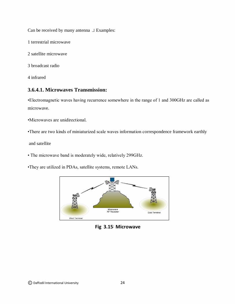
3.6.4.1. Microwaves Transmission:
•Electromagnetic waves having recurrence somewhere in the range of 1 and 300GHz are called as
microwave.
•Microwaves are unidirectional.
•There are two kinds of miniaturized scale waves information correspondence framework earthly
and satellite
• The microwave band is moderately wide, relatively 299GHz.
•They are utilized in PDAs, satellite systems, remote LANs.
Fig 3.15 : Microwave
© Daffodil International University 25
3.6.4.2. Radio waves Transmission:
•Radio waves are especially those waves that engender in the sky mode, can travel long
separation.
•Radio waves are omnidirectional.
•The Radio waves have frequencies between 3 kHz and1Ghz • Mobile communication involves a
few recurrence band under 1 GHz.
•AM and FM radio, TV, sea radio, cordless telephone and paging are instances of multicasting.
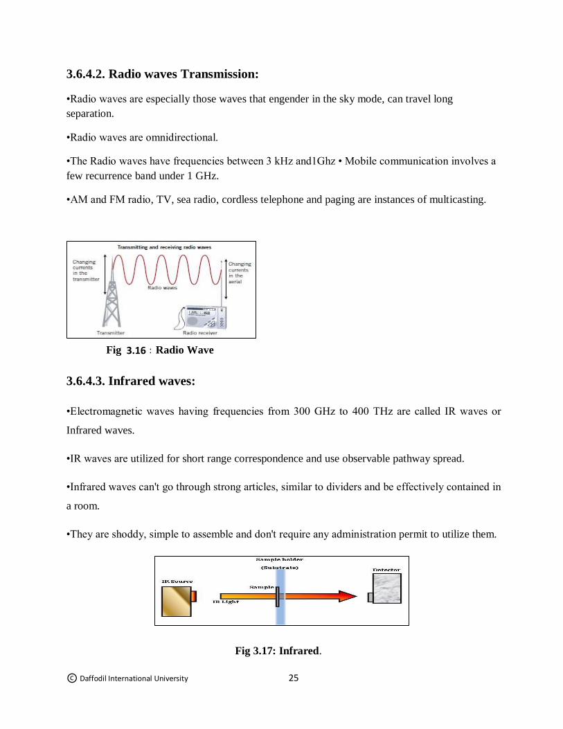
3.6.4.3. Infrared waves:
•Electromagnetic waves having frequencies from 300 GHz to 400 THz are called IR waves or
Infrared waves.
•IR waves are utilized for short range correspondence and use observable pathway spread.
•Infrared waves can't go through strong articles, similar to dividers and be effectively contained in
a room.
•They are shoddy, simple to assemble and don't require any administration permit to utilize them.
Fig 3.17: Infrared.
Fig 3.16 : Radio Wave
© Daffodil International University 26
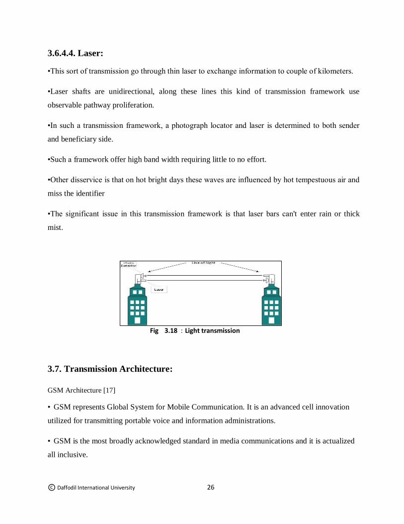
3.6.4.4. Laser:
•This sort of transmission go through thin laser to exchange information to couple of kilometers.
•Laser shafts are unidirectional, along these lines this kind of transmission framework use
observable pathway proliferation.
•In such a transmission framework, a photograph locator and laser is determined to both sender
and beneficiary side.
•Such a framework offer high band width requiring little to no effort.
•Other disservice is that on hot bright days these waves are influenced by hot tempestuous air and
miss the identifier
•The significant issue in this transmission framework is that laser bars can't enter rain or thick
mist.
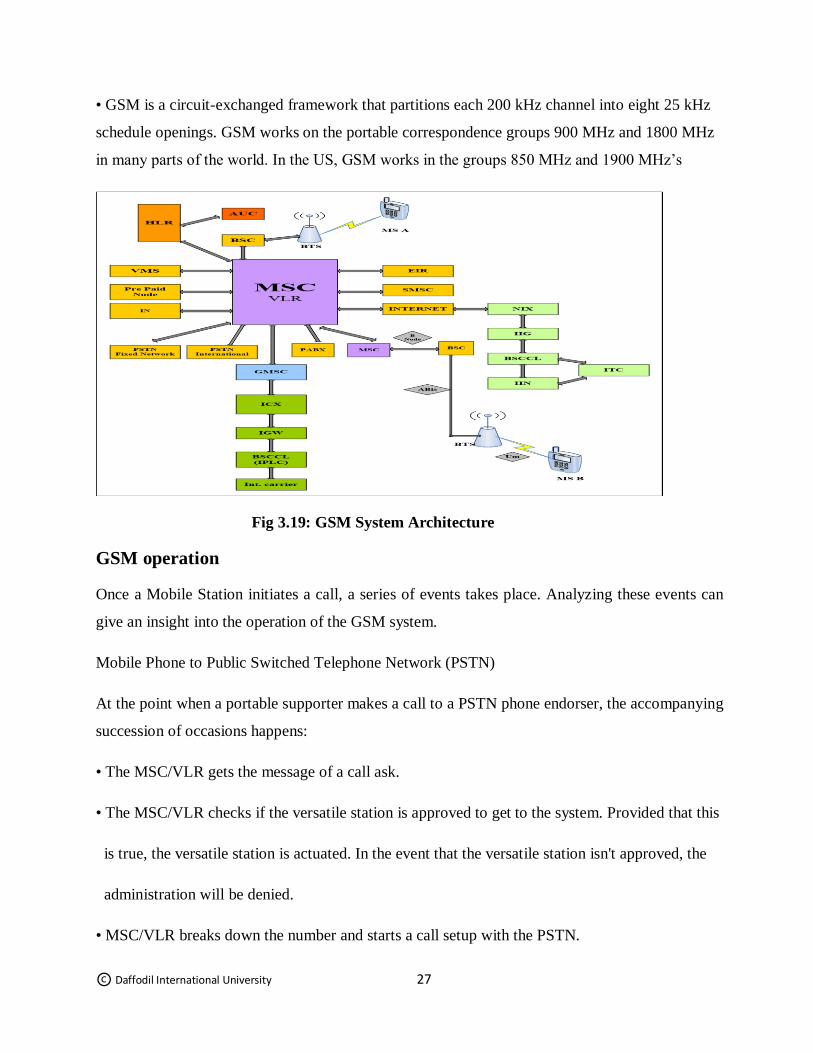
3.7. Transmission Architecture:
GSM Architecture [17]
• GSM represents Global System for Mobile Communication. It is an advanced cell innovation
utilized for transmitting portable voice and information administrations.
• GSM is the most broadly acknowledged standard in media communications and it is actualized
all inclusive.
Fig 3.18 : Light transmission
© Daffodil International University 27
• GSM is a circuit-exchanged framework that partitions each 200 kHz channel into eight 25 kHz
schedule openings. GSM works on the portable correspondence groups 900 MHz and 1800 MHz
in many parts of the world. In the US, GSM works in the groups 850 MHz and 1900 MHz’s
Fig 3.19: GSM System Architecture
GSM operation
Once a Mobile Station initiates a call, a series of events takes place. Analyzing these events can
give an insight into the operation of the GSM system.
Mobile Phone to Public Switched Telephone Network (PSTN)
At the point when a portable supporter makes a call to a PSTN phone endorser, the accompanying
succession of occasions happens:
• The MSC/VLR gets the message of a call ask.
• The MSC/VLR checks if the versatile station is approved to get to the system. Provided that this
is true, the versatile station is actuated. In the event that the versatile station isn't approved, the
administration will be denied.
• MSC/VLR breaks down the number and starts a call setup with the PSTN.
© Daffodil International University 28
• MSC/VLR asks the relating BSC to apportion a traffic channel (a radio channel and a schedule
opening).
• The BSC dispenses the traffic channel and passes the data to the portable station.
• The called party answers the call and the discussion happens.
• The versatile station continues taking estimations of the radio directs in the present cell and the
neighboring cells and passes the data to the BSC. The BSC chooses if a handover is required.
Assuming this is the case, another traffic channel is apportioned to the portable station and the
handover happens. On the off chance that handover isn't required, the versatile station keeps on
transmitting in a similar recurrence.
PSTN to Mobile Phone
At the point when a PSTN endorser calls a versatile station, the accompanying arrangement of
occasions happens:
• The Gateway MSC gets the call and questions the HLR for the data expected to course the call
to the serving MSC/VLR.
• The GMSC courses the call to the MSC/VLR.
• The MSC checks the VLR for the area territory of the MS.
• The MSC contacts the MS by means of the BSC through a communicate message, that is,
through a paging demand.
• The MS reacts to the page ask.
• The BSC dispenses a traffic channel and makes an impression on the MS to tune to the channel.
The MS creates a ringing signal and, after the endorser replies, the discourse association is set up.
• Handover, whenever required, happens, as talked about in the before case.
© Daffodil International University 29
To transmit the discourse over the radio direct in the stipulated time, the MS codes it at the rate of
13 Kbps. The BSC transcodes the discourse to 64 Kbps and sends it over a land connect or a radio
connect to the MSC. The MSC then advances the discourse information to the PSTN. In the
turnaround heading, the discourse is gotten at 64 Kbps at the BSC and the BSC transcodes it to 13
Kbps for radio transmission.
GSM underpins 9.6 Kbps information that can be diverted in one TDMA timeslot. To supply
higher information rates, numerous upgrades were done to the GSM benchmarks (GSM Phase 2
and GSM Phase 2+).
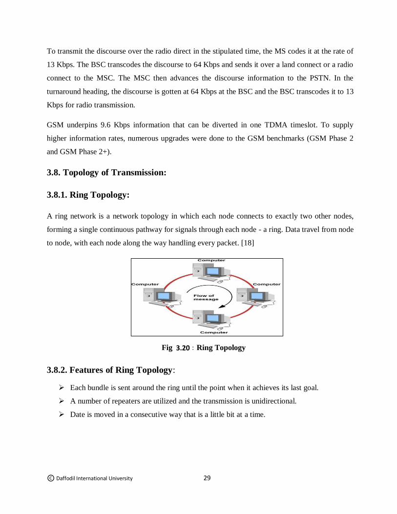
3.8. Topology of Transmission:
3.8.1. Ring Topology:
A ring network is a network topology in which each node connects to exactly two other nodes,
forming a single continuous pathway for signals through each node - a ring. Data travel from node
to node, with each node along the way handling every packet. [18]
3.8.2. Features of Ring Topology:
Each bundle is sent around the ring until the point when it achieves its last goal.
A number of repeaters are utilized and the transmission is unidirectional.
Date is moved in a consecutive way that is a little bit at a time.
Fig 3.20 : Ring Topology
© Daffodil International University 30
3.8.3. Uses of Ring topology:
The ring topology was most regularly utilized in schools, workplaces, and littler
structures where systems were littler.
However, today, the ring topology is only from time to time utilized, having been
changed to another sort of system topology for enhanced execution, security, or support.
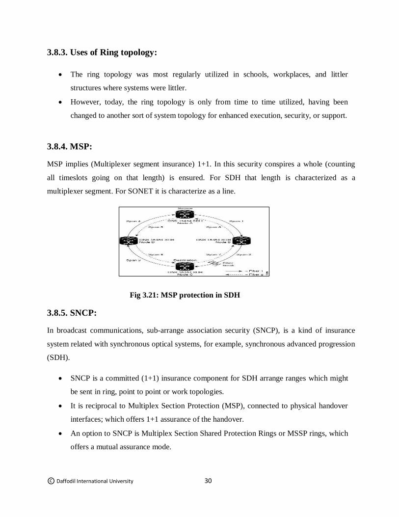
3.8.4. MSP:
MSP implies (Multiplexer segment insurance) 1+1. In this security conspires a whole (counting
all timeslots going on that length) is ensured. For SDH that length is characterized as a
multiplexer segment. For SONET it is characterize as a line.
Fig 3.21: MSP protection in SDH
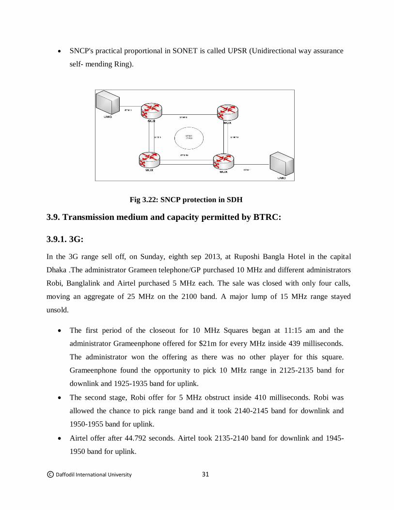
3.8.5. SNCP:
In broadcast communications, sub-arrange association security (SNCP), is a kind of insurance
system related with synchronous optical systems, for example, synchronous advanced progression
(SDH).
SNCP is a committed (1+1) insurance component for SDH arrange ranges which might
be sent in ring, point to point or work topologies.
It is reciprocal to Multiplex Section Protection (MSP), connected to physical handover
interfaces; which offers 1+1 assurance of the handover.
An option to SNCP is Multiplex Section Shared Protection Rings or MSSP rings, which
offers a mutual assurance mode.
© Daffodil International University 31
SNCP's practical proportional in SONET is called UPSR (Unidirectional way assurance
self- mending Ring).
Fig 3.22: SNCP protection in SDH
3.9. Transmission medium and capacity permitted by BTRC:
3.9.1. 3G:
In the 3G range sell off, on Sunday, eighth sep 2013, at Ruposhi Bangla Hotel in the capital
Dhaka .The administrator Grameen telephone/GP purchased 10 MHz and different administrators
Robi, Banglalink and Airtel purchased 5 MHz each. The sale was closed with only four calls,
moving an aggregate of 25 MHz on the 2100 band. A major lump of 15 MHz range stayed
unsold.
The first period of the closeout for 10 MHz Squares began at 11:15 am and the
administrator Grameenphone offered for $21m for every MHz inside 439 milliseconds.
The administrator won the offering as there was no other player for this square.
Grameenphone found the opportunity to pick 10 MHz range in 2125-2135 band for
downlink and 1925-1935 band for uplink.
The second stage, Robi offer for 5 MHz obstruct inside 410 milliseconds. Robi was
allowed the chance to pick range band and it took 2140-2145 band for downlink and
1950-1955 band for uplink.
Airtel offer after 44.792 seconds. Airtel took 2135-2140 band for downlink and 1945-
1950 band for uplink.
© Daffodil International University 32
Just before the finish of the 5 minute time frame for offering, Banglalink joined the race.
Banglalink got whatever is left of the square 2145-2150 band for downlink and 1955-
1960 band for uplink.
The state-possessed versatile administrator Teletalk will get the 3G permit as a matter of
course on 2150-2160 band and it should pay $21m, the cost settled by the sale.
3.9.2. LTE:
Long haul Evolution, LTE is a 4G remote interchanges standard created by the third Generation
Partnership Project (3GPP).
It is intended to give up to 10x the velocities of 3G systems for cell phones, for example, cell
phones, tablets, netbooks, scratch pad and remote hotspots.
The 4G advancements are intended to give IP-based voice, information and mixed media gushing
at paces of no less than 100 Mbit for every second and up to as quickly as 1 GBit for every
second.
4G LTE is one of a few contending 4G gauges alongside Ultra Mobile Broadband (UMB) and
WiMAX.
On February 12, the Ministry of Post and Telecommunication finished the permitting arrangement
for the 3G benefits by settling the estimation of range US$ 20 million for each MHz
© Daffodil International University 33
3.10 Transmission in ICX:
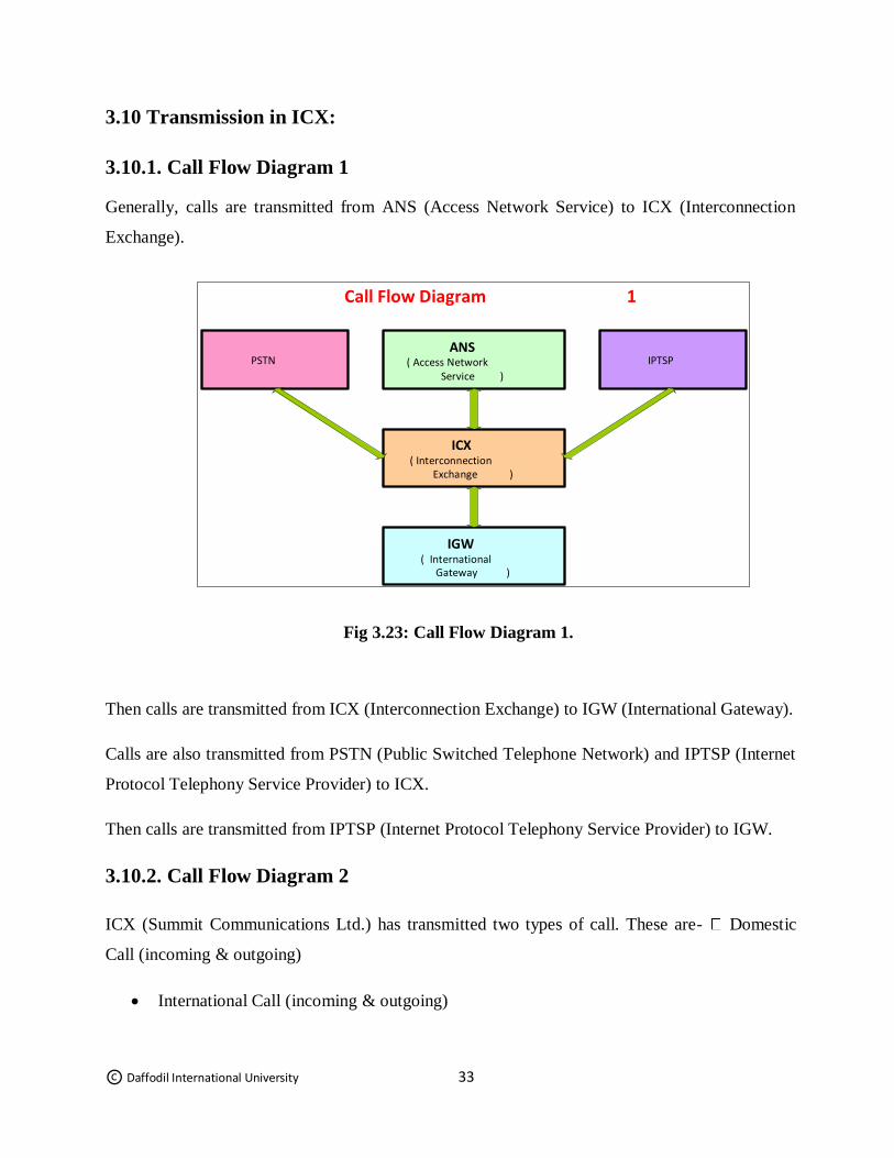
3.10.1. Call Flow Diagram 1
Generally, calls are transmitted from ANS (Access Network Service) to ICX (Interconnection
Exchange).
Fig 3.23: Call Flow Diagram 1.
Then calls are transmitted from ICX (Interconnection Exchange) to IGW (International Gateway).
Calls are also transmitted from PSTN (Public Switched Telephone Network) and IPTSP (Internet
Protocol Telephony Service Provider) to ICX.
Then calls are transmitted from IPTSP (Internet Protocol Telephony Service Provider) to IGW.
3.10.2. Call Flow Diagram 2
ICX (Summit Communications Ltd.) has transmitted two types of call. These are- Domestic
Call (incoming & outgoing)
International Call (incoming & outgoing)
ANS ( Access Network
Service )
ICX ( Interconnection
Exchange )
IGW ( International
Gateway )
Call Flow Diagram 1
IPTSP PSTN
© Daffodil International University 34
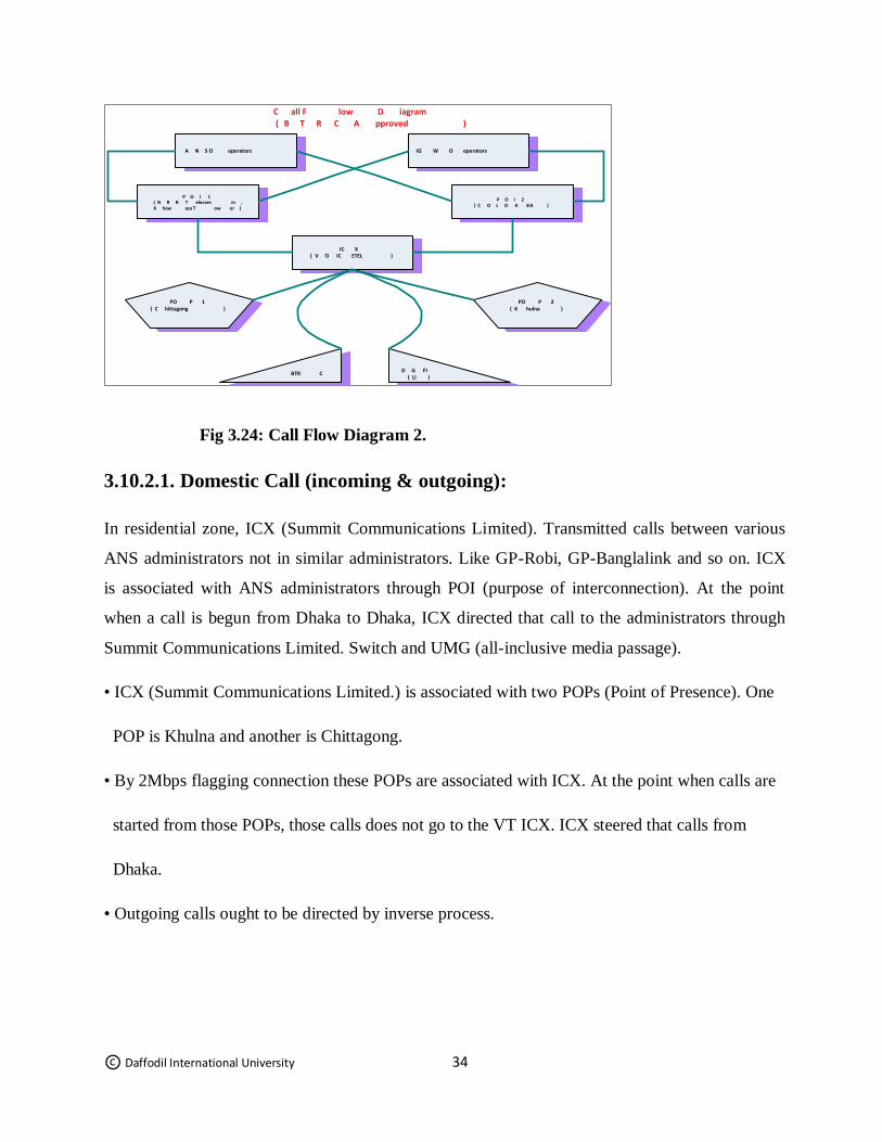
Fig 3.24: Call Flow Diagram 2.
3.10.2.1. Domestic Call (incoming & outgoing):
In residential zone, ICX (Summit Communications Limited). Transmitted calls between various
ANS administrators not in similar administrators. Like GP-Robi, GP-Banglalink and so on. ICX
is associated with ANS administrators through POI (purpose of interconnection). At the point
when a call is begun from Dhaka to Dhaka, ICX directed that call to the administrators through
Summit Communications Limited. Switch and UMG (all-inclusive media passage).
• ICX (Summit Communications Limited.) is associated with two POPs (Point of Presence). One
POP is Khulna and another is Chittagong.
• By 2Mbps flagging connection these POPs are associated with ICX. At the point when calls are
started from those POPs, those calls does not go to the VT ICX. ICX steered that calls from
Dhaka.
• Outgoing calls ought to be directed by inverse process.
I P O 1 ( B m elecom T R N ,
aza T ow K er haw )
X IC
( ETEL V IC O )
P PO 2 ( hulna K ) P PO 1
( hittagong C )
operators A S O N
C all F low D iagram
( A C pproved R T B )
P O I 2 ( C O A SIA L O )
IG operators O W
C BTR D G FI ( LI )
© Daffodil International University 35
3.10.2.2. International Call (incoming & outgoing):
If there should be an occurrence of International call, when anybody calls from Dhaka to
whatever other global nation that call will spill out of ANS to ICX. At that point ICX to POI and
afterward POI to IGW.
• ICX will steered the calls from those IGWs which interface execution will be better.
• If any calls started from POP to any universal nation, at first call will spill out of POP to ANS.
At that point will go from ANS to ICX. At that point from ICX to POI and POI to IGW.
• The ICX will be fit for creating CDRs (call definite record) and recording point of interest
information of every single finished call (both approaching and active) for every one of the
circuit in any or all circuit gatherings. Call Detail Record (CDR) is to convey every day BTRC
(Bangladesh Telecommunication Regulatory Commission).
• DGFI (Directorate General of Forces Intelligence) can get to whenever to the UMG, switch,
charging for any sort of security reason.
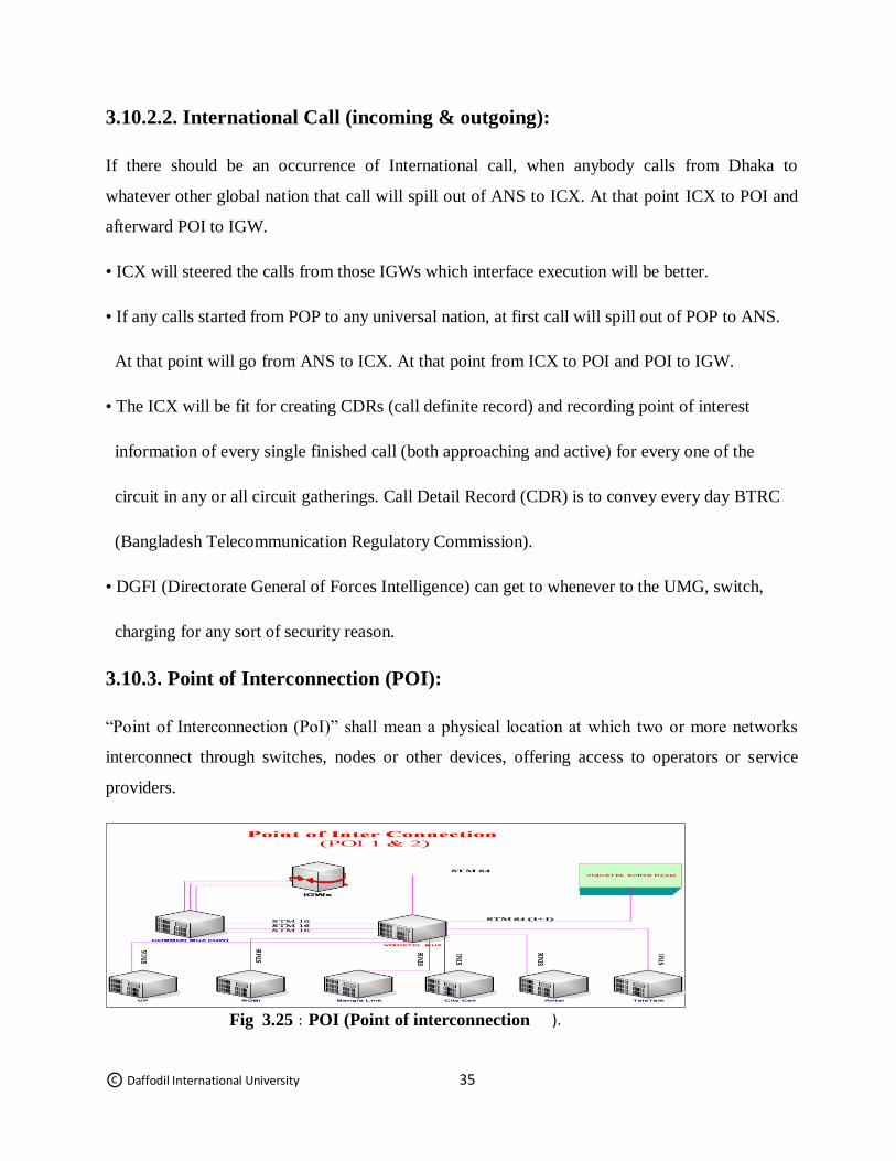
3.10.3. Point of Interconnection (POI):
“Point of Interconnection (PoI)” shall mean a physical location at which two or more networks
interconnect through switches, nodes or other devices, offering access to operators or service
providers.
Fig 3.25 : POI (Point of interconnection ).
© Daffodil International University 36
In Summit Communications Limited. Ltd., there has two POI-
- POI (NRB)
- POI (COLOASIA)
• All IGWs are associated with regular IGW MUX.
• In broadcast communications and PC systems, multiplexing (now and again contracted to
mixing) is a technique by which numerous simple message signals or computerized information
streams are consolidated into one flag over a common medium.
• The point is to share a costly asset. The multiplexed flag is transmitted over a correspondence
station, for example, a link.
• The multiplexing partitions the limit of the correspondence channel into a few intelligent
channels, one for each message flag or information stream to be exchanged. An invert
procedure, known as de-multiplexing, extricates the first channels on the beneficiary end. A
gadget that plays out the multiplexing is known as a multiplexer (MUX), and a gadget that plays
out the turnaround process is known as a de-multiplexer (DEMUX or DMX).
• IN POI (NRB), Summit Communications Limited. MUX (OSN 3500) is associated with the
IGWs normal MUX by two STM 16 interface, associated with the Summit Communications
Limited. Switch Room MUX (OSN 3500) by two STM 64 connection and associated with the
ANS administrators (like GP, BL, Robi, Citycell, and Teletalk).
• Summit Communications Limited. MUX (OSN 3500) is associated with Robi, GP, Banglalink,
Airtel by STM 16 connection and Citycell, Teletalk are associated with STM 1 interface.
© Daffodil International University 37
• In POI (COLOASIA), Summit Communications Limited. MUX (OSN 2500) is associated with
Summit Communications Limited. Switch Room MUX (OSN 3500) by two STM 16 interface.
One is excess STM (MSP (1+1)). POI (OSN 2500) is a low limit MUX. It gives just household
calls to those administrators which just need.
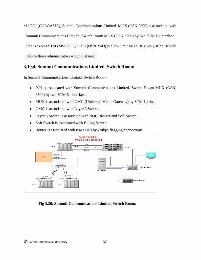
3.10.4. Summit Communications Limited. Switch Room:
In Summit Communications Limited. Switch Room-
POI is associated with Summit Communications Limited. Switch Room MUX (OSN
3500) by two STM 64 interface.
MUX is associated with UMG (Universal Media Gateway) by STM 1 joins.
UMG is associated with Layer 3 Switch.
Layer 3 Switch is associated with NOC, Router and Soft Switch.
Soft Switch is associated with Billing Server.
Router is associated with two POPs by 2Mbps flagging connections.
Fig 3.26: Summit Communications Limited Switch Room.
© Daffodil International University 38
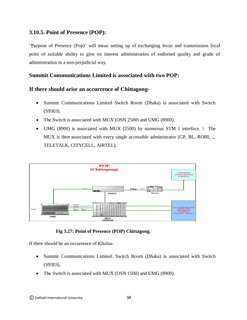
3.10.5. Point of Presence (POP):
"Purpose of Presence (Pop)" will mean setting up of exchanging focus and transmission focal
point of suitable ability to give on interest administration of endorsed quality and grade of
administration in a non-prejudicial way.
Summit Communications Limited is associated with two POP:
If there should arise an occurrence of Chittagong-
Summit Communications Limited Switch Room (Dhaka) is associated with Switch
(S9303).
The Switch is associated with MUX (OSN 2500) and UMG (8900).
UMG (8900) is associated with MUX (2500) by numerous STM 1 interface. The
MUX is then associated with every single accessible administrator (GP, BL, ROBI,
TELETALK, CITYCELL, AIRTEL).
Fig 3.27: Point of Presence (POP) Chittagong.
If there should be an occurrence of Khulna-
Summit Communications Limited. Switch Room (Dhaka) is associated with Switch
(S9303).
The Switch is associated with MUX (OSN 1500) and UMG (8900).
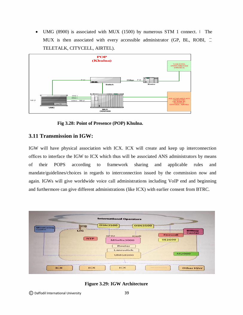
© Daffodil International University 39
UMG (8900) is associated with MUX (1500) by numerous STM 1 connect. The
MUX is then associated with every accessible administrator (GP, BL, ROBI,
TELETALK, CITYCELL, AIRTEL).
Fig 3.28: Point of Presence (POP) Khulna.
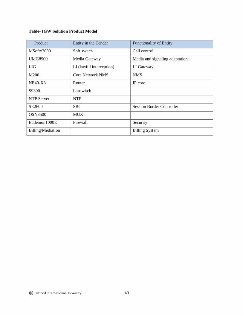
3.11 Transmission in IGW:
IGW will have physical association with ICX. ICX will create and keep up interconnection
offices to interface the IGW to ICX which thus will be associated ANS administrators by means
of their POPS according to framework sharing and applicable rules and
mandate/guidelines/choices in regards to interconnection issued by the commission now and
again. IGWs will give worldwide voice call administrations including VoIP end and beginning
and furthermore can give different administrations (like ICX) with earlier consent from BTRC.
Figure 3.29: IGW Architecture
© Daffodil International University 40
Table- IGW Solution Product Model
Product Entity in the Tender Functionality of Entity
MSoftx3000 Soft switch Call control
UMG8900 Media Gateway Media and signaling adaptation
LIG LI (lawful interception) LI Gateway
M200 Core Network NMS NMS
NE40-X3 Router IP core
S9300 Lanswitch
NTP Server NTP
SE2600 SBC Session Border Controller
OSN3500 MUX
Eudemon1000E Firewall Security
Billing/Mediation Billing System
© Daffodil International University 41
Chapter 4
Geographical Device Interfaces
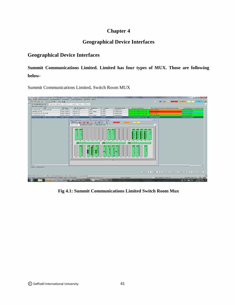
Geographical Device Interfaces
Summit Communications Limited. Limited has four types of MUX. Those are following
below-
Summit Communications Limited. Switch Room MUX
Fig 4.1: Summit Communications Limited Switch Room Mux
© Daffodil International University 42
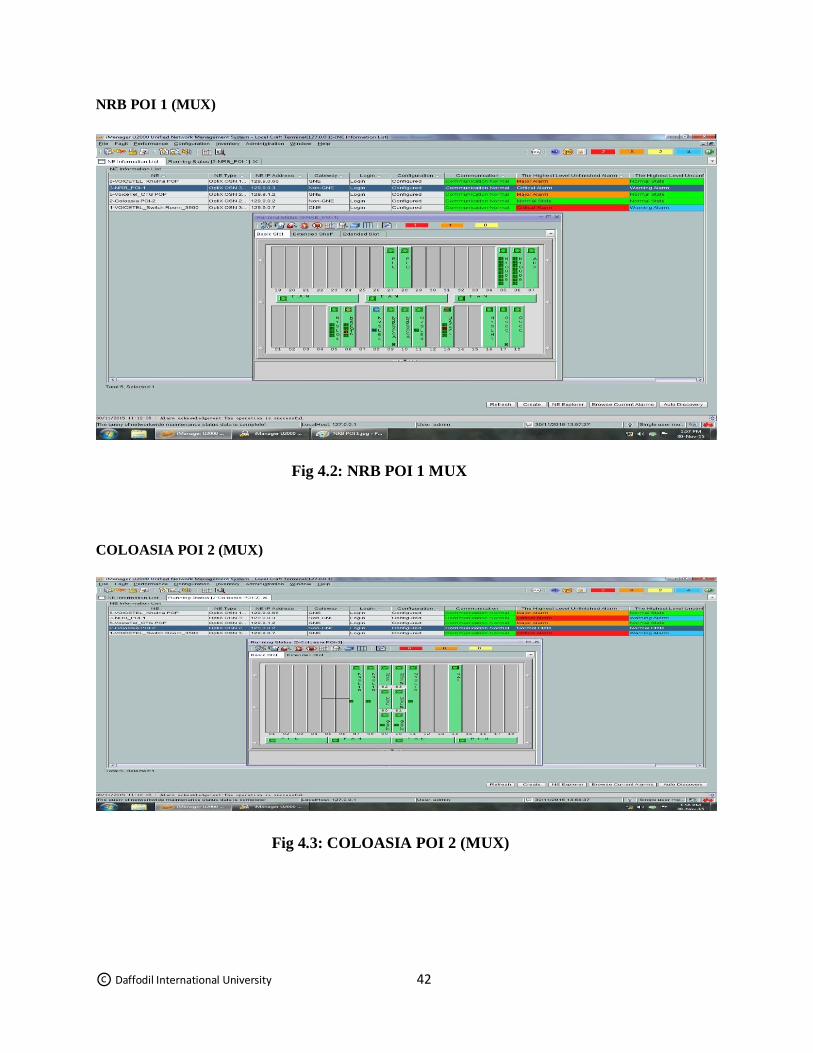
NRB POI 1 (MUX)
Fig 4.2: NRB POI 1 MUX
COLOASIA POI 2 (MUX)
Fig 4.3: COLOASIA POI 2 (MUX)
© Daffodil International University 43
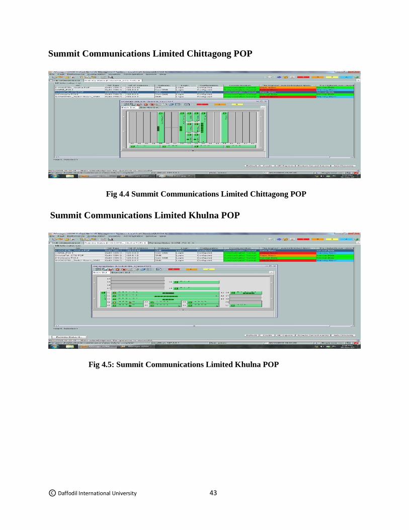
Summit Communications Limited Chittagong POP
Fig 4.4 Summit Communications Limited Chittagong POP
Summit Communications Limited Khulna POP
Fig 4.5: Summit Communications Limited Khulna POP
© Daffodil International University 44
Chapter 5
Alarm systems
5. ALARM
However working in NOC (Network Operation Center) section, there are getting some following
types of common alarms in the physical transmission-
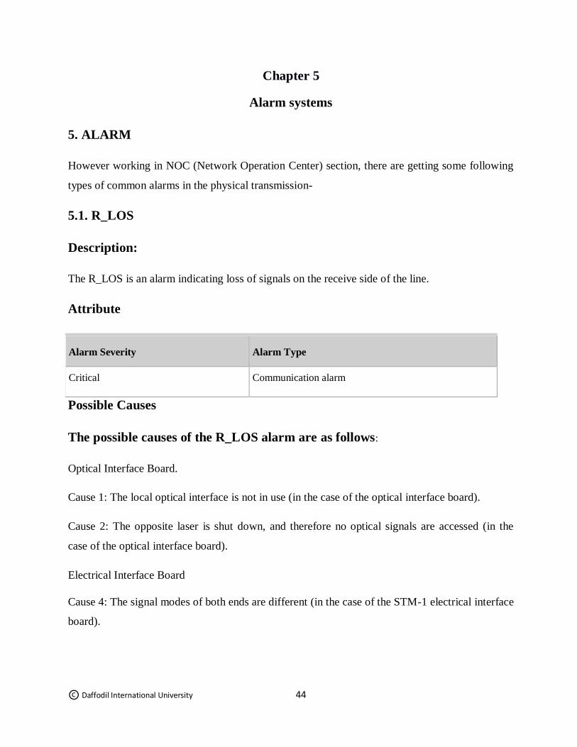
5.1. R_LOS
Description:
The R_LOS is an alarm indicating loss of signals on the receive side of the line.
Attribute
Alarm Severity Alarm Type
Critical Communication alarm
Possible Causes
The possible causes of the R_LOS alarm are as follows:
Optical Interface Board.
Cause 1: The local optical interface is not in use (in the case of the optical interface board).
Cause 2: The opposite laser is shut down, and therefore no optical signals are accessed (in the
case of the optical interface board).
Electrical Interface Board
Cause 4: The signal modes of both ends are different (in the case of the STM-1 electrical interface
board).
© Daffodil International University 45
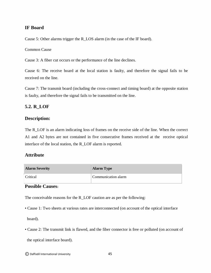
IF Board
Cause 5: Other alarms trigger the R_LOS alarm (in the case of the IF board).
Common Cause
Cause 3: A fiber cut occurs or the performance of the line declines.
Cause 6: The receive board at the local station is faulty, and therefore the signal fails to be
received on the line.
Cause 7: The transmit board (including the cross-connect and timing board) at the opposite station
is faulty, and therefore the signal fails to be transmitted on the line.
5.2. R_LOF
Description:
The R_LOF is an alarm indicating loss of frames on the receive side of the line. When the correct
A1 and A2 bytes are not contained in five consecutive frames received at the receive optical
interface of the local station, the R_LOF alarm is reported.
Attribute
Alarm Severity Alarm Type
Critical Communication alarm
Possible Causes:
The conceivable reasons for the R_LOF caution are as per the following:
• Cause 1: Two sheets at various rates are interconnected (on account of the optical interface
board).
• Cause 2: The transmit link is flawed, and the fiber connector is free or polluted (on account of
the optical interface board).
© Daffodil International University 46
• Cause 3: Other cautions trigger the R_LOF alert (on account of the IF board).
• Cause 4: The get board at the nearby station is flawed, and along these lines the edge structure is
lost.
• Cause 5: The transmit board (counting the cross-interface board) at the contrary station is
flawed, and accordingly the edge structure is lost.
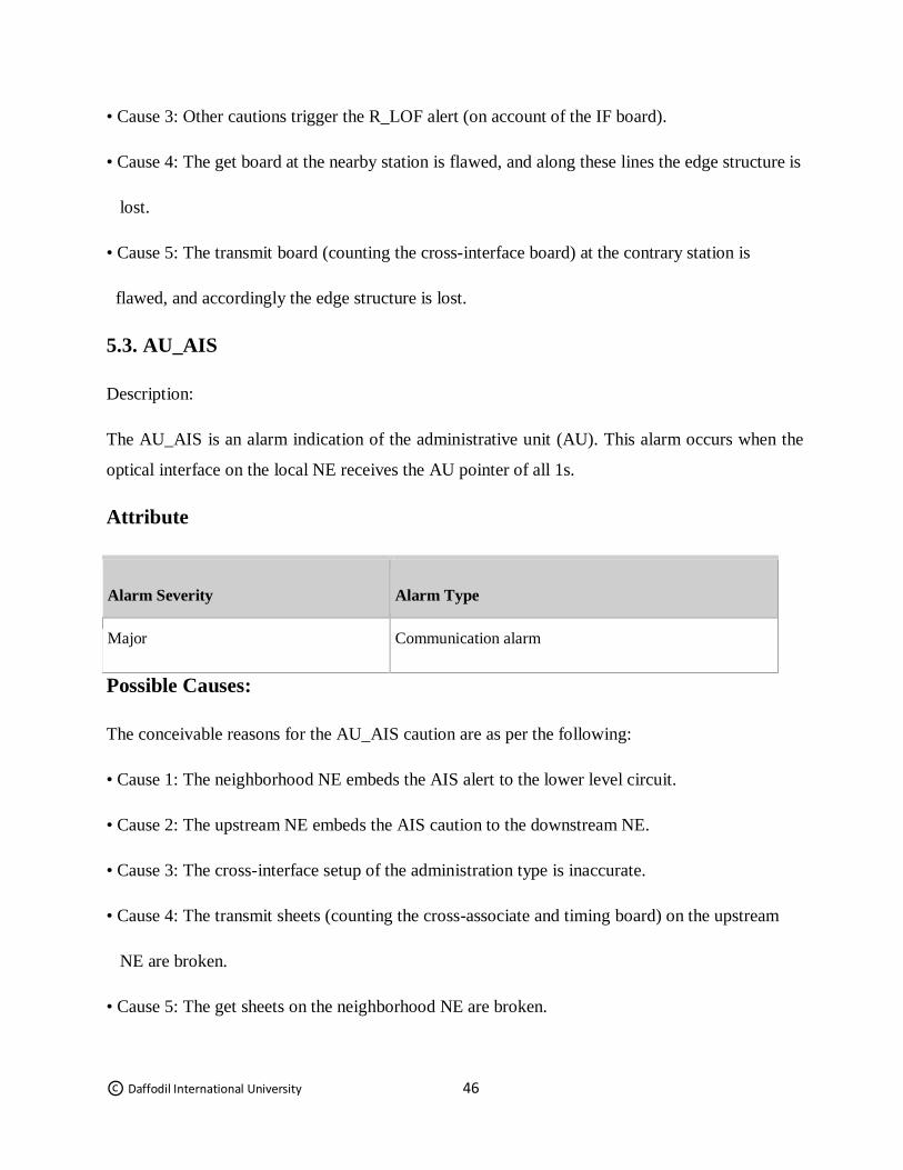
5.3. AU_AIS
Description:
The AU_AIS is an alarm indication of the administrative unit (AU). This alarm occurs when the
optical interface on the local NE receives the AU pointer of all 1s.
Attribute
Alarm Severity Alarm Type
Major Communication alarm
Possible Causes:
The conceivable reasons for the AU_AIS caution are as per the following:
• Cause 1: The neighborhood NE embeds the AIS alert to the lower level circuit.
• Cause 2: The upstream NE embeds the AIS caution to the downstream NE.
• Cause 3: The cross-interface setup of the administration type is inaccurate.
• Cause 4: The transmit sheets (counting the cross-associate and timing board) on the upstream
NE are broken.
• Cause 5: The get sheets on the neighborhood NE are broken.
© Daffodil International University 47
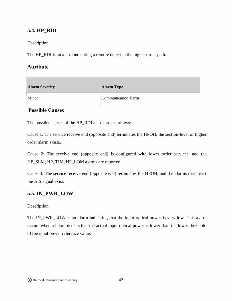
5.4. HP_RDI
Description
The HP_RDI is an alarm indicating a remote defect in the higher order path.
Attribute
Alarm Severity Alarm Type
Minor Communication alarm
Possible Causes
The possible causes of the HP_RDI alarm are as follows:
Cause 1: The service receive end (opposite end) terminates the HPOH, the section-level or higher
order alarm exists.
Cause 2: The receive end (opposite end) is configured with lower order services, and the
HP_SLM, HP_TIM, HP_LOM alarms are reported.
Cause 3: The service receive end (opposite end) terminates the HPOH, and the alarms that insert
the AIS signal exist.
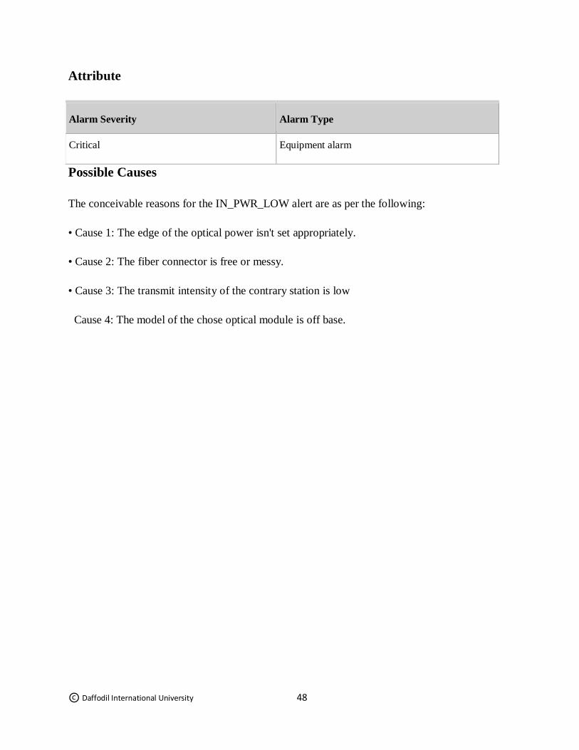
5.5. IN_PWR_LOW
Description
The IN_PWR_LOW is an alarm indicating that the input optical power is very low. This alarm
occurs when a board detects that the actual input optical power is lower than the lower threshold
of the input power reference value.
© Daffodil International University 48
Attribute
Alarm Severity Alarm Type
Critical Equipment alarm
Possible Causes
The conceivable reasons for the IN_PWR_LOW alert are as per the following:
• Cause 1: The edge of the optical power isn't set appropriately.
• Cause 2: The fiber connector is free or messy.
• Cause 3: The transmit intensity of the contrary station is low
Cause 4: The model of the chose optical module is off base.
© Daffodil International University 49
Chapter 6
Conclusion
6.1 Conclusion
This paper has taken a detailed look at the transmission system of ICX in Summit
Communications Limited (SCL). ICX is not a worldwide organization, it’s having only
Bangladesh. Summit Communications Limited (SCL) received an ICX License from BTRC in
2012 which allows SCL to establish, operate and maintain the interconnection exchange services
to provide telecommunication services (terminating to and originating from Bangladesh). SCL
provides routing or switching facilities for inter-operator domestic voice calls and international
calls between Access Network Service Operators and International Voice Gateways. We have
established our infrastructure in Dhaka, Chittagong and Sylhet. We are connected to all mobile
phone operators, PSTN operators and IGWs of the country. SCL is the pioneer to route local,
international and roaming call facilities among 26 ICXs in Bangladesh because of its best-in-class
Quality of Service (QoS), loss-less voice quality and optimal routing solutions.
SCL is currently capable of carrying 49750 concurrent calls
Present BHCA is 3 - 3.5 million
Handling 7-10 million Local call minutes per day
Handling 3-5 million International call minutes per day
ICX is used only to increase the security of telecommunication system and will
permitted/licensed by the government
© Daffodil International University 50
REFERENCE
[1] https://www.summitcommunications.net [Accessed Time: 10:39 PM 12-Dec-18]
[2] https://en.wikipedia.org/wiki/Transmission_(telecommunications) [Accessed Time: 10:48 PM
12-Dec-18]
[3] https://en.wikipedia.org/wiki/Data_transmission [Accessed Time: 10:56 PM 12-Dec-18]
[4] https://en.wikipedia.org/wiki/Network packet [Accessed Time: 11:05 PM 12-Dec-18]
[5] http://whatis.techtarget.com/definition/time-division-multiplexing-TDM [Accessed Time:
11:14 PM 12-Dec-18]
[6] https://en.wikipedia.org/wiki/Power_transmission[Accessed Time: 11:23 PM 12-Dec-18]
[7] http://whatis.techtarget.com/definition/time-division-multiplexing-TDM [Accessed Time:
11:32 PM 12-Dec-18]
[8] https://www.techopedia.com/definition/21314/plesiochronous-digital-hierarchy-pdh[Accessed
Time: 11:41 PM 12-Dec-18]
[9] http://searchnetworking.techtarget.com/definition/SDH[Accessed Time: 11:50 PM 12-Dec-18]
[10] https://whatismyipaddress.com/vpn [Accessed Time: 11:59 PM 12-Dec-18]
[11] https://en.wikipedia.org/wiki/Multiprotocol_Label_Switching [Accessed Time: 12:08 AM
13-Dec-18]
[12] https://en.wikipedia.org/wiki/Virtual_Private_LAN_Service [Accessed Time: 12:17 AM 13-
Dec-18]
[13] https://searchnetworking.techtarget.com/ [Accessed Time: 12:26 AM 13-Dec-18]
[14] https://searchmobilecomputing.techtarget.com/definition/W-CDMA [Accessed Time: 12:35
AM 13-Dec-18]
[15] http://ecomputernotes.com/computernetworkingnotes/communication-networks/what-
media-and-types-of-transmission-media [Accessed Time: 12:44 AM 13-Dec-18]
[16] http://www.tutorialspoint.com/gsm/gsm_operations.htm [Accessed Time: 01:02 AM 13-
Dec-18]
[17] https://en.wikipedia.org/wiki/Ring_network [Accessed Time: 01:11 AM 13-Dec-18]