Embed Size (px)
Citation preview
DESIGN AND OPERATION OF RDMA BASED ROUTING ARCHITECTURE
A Thesis by
Rama Chandra Kumar Maram
Bachelor’s Degree, Rajeev Gandhi Memorial College of Engineering and Technology, JNTU, India, 2005
Submitted to Department of Electrical and Computer Engineering and faculty of the Graduate School of
Wichita State University in partial fulfillment of
the requirements for the degree of Master of Science
December 2008

© Copyright 2008 by Rama Chandra Kumar Maram
All Rights Reserved
iii
DESIGN AND OPERATION OF RDMA BASED ROUTING ARCHITECTURE
The following faculty members have examined the final copy of this thesis for form and content, and recommended that it be accepted in partial fulfillment of the requirement for the degree of Master of Science with a major in Electrical Engineering.
_______________________
Ravi Pendse, Committee Chair
_______________________
Edwin Sawan, Committee Member
_______________________
Krishna Krishnan, Committee Member

iv
DEDICATION
To my parents, teacher, my friends and my sisters,
for their constant encouragement and support.

v
ACKNOWLEDGEMENT
I would like to thank my advisor, Dr. Ravi Pendse for giving me an opportunity to do my
thesis work under his guidance. I would like to thank my committee for taking the time to work
with me in this endeavor. I am thankful to Mr. Nagaraja Thanthry for his valuable advice, time
and timely help during my thesis work. I am forever indebted for my parents and my family for
supporting and encouraging me throughout my life to achieve higher goals.
vi
ABSTRACT
Internet, a connection of networks has unified the world with no boundaries and
limitations. It fulfilled the dream of being virtually present in any part of the world within no
time. Over the years internet spanned into every corner of the world and a tremendous growth in
the use of internet had been noticed. Internet, with its numerous advantages and support of wide
variety of applications has leaded the consumer demand for more bandwidth and high
availability to meet his requirements. Addressing these factors great development has taken place
in recent years in the field of network technologies. A new era of Gigabit and Terabit Ethernet
technologies signify the developments that address the growing demands. With the development
in Ethernet technologies the demand for new router architectures that could process the data at
gigabit rates also has increased. Many different router architectures have been proposed and
implemented to meet these requirements.
In this thesis, different router architectures have been studied and explained in detail.
Many factors that affect the performance of the router have been reviewed and solutions to
overcome the limitations have been addressed in detail. Addressing the solutions for limitations
seen in legacy router architectures, the author presents the design, operation of a proposed new
routing architecture [16]. The proposed architecture introduces the operation of RDMA into
router architecture to minimize the processing and forwarding delay, which improves the
performance of routers. The operation of an RDMA enabled router and the operation between
two RDMA enabled routers have been clearly explained. The author also presents the
mathematical models for evaluating the delay within a router and between two routers, processor
utilization and memory utilization for both the legacy and RDMA enabled router architectures.
In order to understand the router operation in detail and to enable future researchers to work on
vii
router architecture, a simulator with router operation has been built for both the router
architectures. The results show that the proposed architectural operation improves the
performance of routers even in heavy traffic networks.
viii
TABLE OF CONTENTS
Chapter Page
1. INTRODUCTION………………………..………………………….………....1 1.1 TCP/IP Architecture…………..………………………………………….2 1.2 Performance Issues ………………..…………………………………......6
1.2.1 Current issues and problems ……………………………………......7 1.3 Problem description ……….…………………………………………….7 1.4 Organization of Thesis …….……………………………………………8
2. ROUTER OPERATION & EVOLUTION OF ROUTER ARCHITECTURES.9
2.1 Introduction…………………………………………………………........9 2.1.1 Network Types……………………………………………..………..10
2.2 Components of a router …….…………………………………………...12 2.2.1 Hardware components of a router….……………………………….12 2.2.2 Control and Data Paths in a router………………………………….13 2.2.3 Back Plane……………………………………………………….…14
2.3 Operation of a router and packet handling procedure………….……….14 2.3.1 Packet processing………………………………………….…….…14 2.3.2 Packet Forwarding ….……………………………………………..14 2.3.3 Other Services ……………………………………………………..17
2.4 Router Architectures……………………………………………………17 2.4.1 1st Generation Router Architecture…….…………………………..17 2.4.2 2nd Generation Router Architecture ……………………………......19 2.4.3 3rd Generation Router Architecture …………….………………….21
3. RDMA ………………………………………………………………………..23
3.1 Introduction to RDMA …………………………………………………23 3.2 DMA ……..……………………………………………………………..24 3.3 Overview of Operation of RDMA …… ………………………………..25 3.4 General Terms ……………………………………………………….…27 3.5 RDMAP Layering ………………………………………………….......29
3.5.1 Explanation………………………………………………………...31 3.5.1.1 RDMAP …………………………………………………….31 3.5.1.2 ULP Interaction with RDMAP layer Send …………………32
ix
TABLE OF CONTENTS (continued)
Chapter Page
3.5.1.3 ULP Interaction with RDMAP layer Write………………....32 3.5.1.4 ULP Interaction with RDMAP layer Read ….………………33 3.5.1.5 RDMA Header Format ……….……………………………..33
3.5.2 DDP Layer ……………………………………………..……..….34 3.5.2.1 Tagged Buffer Transfer Model ……………………….….....34 3.5.2.2 Untagged Buffer Transfer Model …………………………..35 3.5.2.3 DDP Header …….…………………………………………..35
3.5.3 MPA Layer …..…………………………………………….…….36 3.5.4 TCP Layer …..…………………………………………………...36 3.5.5 RDMA Data Transfer mechanisms ….……………………….….37
3.5.5.1 RDMA Write …….………………………………………….37 3.5.5.2 RDMA Read ……………………………………………..…38 3.5.5.3 RDMA Send ……………………………………………..…39 3.5.5.4 Terminate …….……………………………………….…….39 3.5.5.5 RDMA Stream Initialization …………………….…….……39 3.5.5.6 RDMA Stream Teardown ………….……………………….40 3.5.5.7 RDMA Error Management …………………………………40
3.6 RNIC ……………………………………………………..………….…41 3.7 RDMA verbs ………………………………………………..………….41 3.8 RNIC interface …….………………………………………….………..42
4. RDMA ENABLED ROUTER’S ARCHITECTURE AND ITS
OPERATION………………………………………………………………….44 4.1 Introduction …………………………………………………………….44 4.2 Proposed Changes to routing update Packet ………………………..….44 4.3 Proposed Routing Architecture and its operation ………………….…..47 4.4 Functionalities of Different Components of a Line card………….……49 4.5 Operation of RDMA enabled router……………….…………….……...53
4.5.1 Data Flow Sequence ….……………………………………...…….54 4.5.2 Operation within a router …………………………………………..55 4.5.3 Operation in between two routers ….……………………………....56
4.5.3.1 Functionalities Of Hardware Components …….……….…...57 4.6 Stream Teardown …….………………………………………………....59

x
TABLE OF CONTENTS (continued)
Chapter Page
5. MATHEMATICAL ANALYSIS, SIMULATION AND RESULTS …….…..61 5.1 Performance …………………………………………………….……....61
5.1.1 Transmission Delay in a Conventional Router …..……………....63 5.1.2 Queuing Delay…..……………………………………………......63 5.1.3 Delay in a RDMA enabled Router ….…………………………...65
5.2 Processing and Transmission Delay between routers …….…………....67 5.2.1 Processing Delay in packet processing …..………………………68
5.3 Memory Utilization …………………………………………………….70 5.3.1 Memory Utilization in a Conventional Router …….…………….70 5.3.2 Memory Utilization in a RDMA enabled Router …..……………73
5.4 CPU UTILIZATION ……………………...……….…………………...74 5.4.1 CPU Utilization in a Conventional router……….……….……....74 5.4.2 CPU Utilization in a RDMA enabled router ….…………...…….75
5.5 Router Simulator …………………………………….…………………75 5.5.1 Simulator Explanation ……………………….……………..……75 5.5.2 Description of Simulator …………………….…………………..76 5.5.3 Simulator Environment ….…………………….………………...77 5.5.4 Snapshots of Simulator ….…………………………………….....77
5.6 Results and Analysis……………………………………………….……78 5.6.1 Delay within a router………………………….……………..….. 78 5.6.2 Delay in between two routers…………………………………….80 5.6.3 Memory Utilization ………………….……………………..……82 5.6.4 CPU Utilization ……………………….………………………....83
6. CONCLUSIONS AND FUTURE WORK……..……………………………..85
6.1 Conclusion …….……………………………….……………………….85 6.2 Future Work ……………………………………………………………85
REFERENCES…………….…………………………………………………………..86
APPENDICES …………………………………………………………………………90

xi
LIST OF TABLES
Table Page
5.1 Delay variation between conventional and RDMA based router … …………….80
5.2 Memory values …………………………….…………………………………….82
5.3 CPU cycles for the different operations………………………………………….83
xii
LIST OF FIGURES
Figure Page
1.1 TCP/IP Model……… …………………………………………………….…..…. 2
1.2 TCP/IP Model with protocols ………………..………………………….……….. 5
2.1 Functional Components of a router .………………………………………….… 15
2.2 Centralized routing architecture ………………………………….…….………..18
2.3 Distributed routing architecture……………………………………………….....20
2.4 Switched Plane architecture…………………………………………...…………22
3.1 RDMAP Layering………………………………………………………………...30
3.2 RDMA, DDP, MPA header alignment over TCP………………….…….........…30
3.3 RDMA header ………………………………………………………..……..…...33
3.4 DDP Control Field……………………………………………………………….35
3.5 RDMA write message, DDP segment Format…………………………………...37
3.6 RNIC in a Stack……………………………………………………………....….41
4.1 Original RIP update packet………………………………………..………….….46
4.2 RIP Update packet with egress field included…………………………….……..46
4.3 RDMA enabled router architecture……………………………………….……...47
4.4 Different components in RDMA enabled router………………………..………..49
4.5 Data Flow sequence in a RDMA enabled router………………………………....54
4.6 Figure showing connection between two routers.............................................…..56
xiii
LIST OF FIGURES (continued)
Figure Page
5.1 Routing table output……………………………………………………………….78
5.2 Delay variation with number of packets in a router ………………………..…….79
5.3 Delay variation with number of packets in between two routers…………………81
5.4 Delay variation with number of sessions …………………………………..…….81
5.5 Memory variation with different packet sizes……………………………..……..82
5.6 CPU utilization with varying packet size……………………………………..….83
A1-A10 Simulator outputs …………………………………………………….……….90

xiv
ACRONYMS
ACK Acknowledgement
ARPANET Advanced Research Projects Agency Network
CMOS Complimentary Metal-Oxide Semiconductor
CPU Central Processing unit
CQ Completion Queue
CRC Cyclic Redundancy Check
DDP Direct Data protocol
DMA Direct Memory Access
DoD Department of Defense
DRAM Dynamic Random Access Memory
DV DDP Version
FPDU Frame Protocol Data unit
IETF Internet Engineering Task Force
IGP Interior Gateway Protocol
IGRP Interior Gateway Routing Protocol
IP Internet Protocol
I/O Input and Output
ISO International Standards Organization
iWARP Internet Wide Area RDMA Protocol
LLP Lower layer Protocol
MPA Marker Based Protocol Data Unit
MTU Maximum Transmission Unit
NIC Network Interface Card
xv
ACRONYMS (continued)
OS Operating Systems
OSI Open System Interconnection
OSPF Open Shortest Path First
PDU Protocol data unit
QOS Quality of Service
RDMA Remote Direct Memory Access
RIP Routing Information Protocol
RNIC RDMA Network Interface Card
RSVD Reserved
RSVDULP Reserved Upper Layer Protocol
SCTP Stream control Transmission Protocol
SNMP Simple Network Management Protocol
SQ Send Queue
SRQ Shared Queue
Stag Steering Tag
SYNACK Synchronized Acknowledgement
TCP Transmission Control Protocol
TTL Time to Live
ULP Upper Layer Protocol
WQ Work Queue
1
CHAPTER 1
INTRODUCTION
Internet, the technology that was born in early in 1970’s revolutionized the field of
technology with its ability to share the information with any one in any part of the world. Internet
which is known as network of networks [4] not only connects millions of people round the globe
but also includes different technologies in its operation. Internet provides the medium to
collaborate, interact and share information with any individual irrespective of the geographic
location. The basic concept of internet which allows two computers talk to each other over the
network comes from ARPANET. After the development in internet the next issue that concerned
the researchers was to provide reliable communication over the network, this lead to the
introduction of TCP/IP architecture. With the development and increase in the use of internet
there required a common architecture with which the networks can connect. ISO defined a
common way to connect computers. OSI architecture given by ISO divides the network
functionality into seven layers. Division of layers restricts the problems to the layer itself and
gives the users ease to resolve the problems that arise over the network [6]. Internet architecture
which is also known as TCP/IP architecture provides the functionality of seven layers of OSI
model and is used as a de-facto standard in the operation of internet. With the growth in the size
of the networks there stood other problems such as CPU bottleneck in the networking devices,
delay and throughput which affected the overall performance of network. In order to address
these problems many solutions and different technologies have been proposed over the years.
Each of these technologies is discussed in the following sections. The factors that affect the
router performance and work done to overcome these problems are also discussed.

2
1.1 TCP/IP architecture:
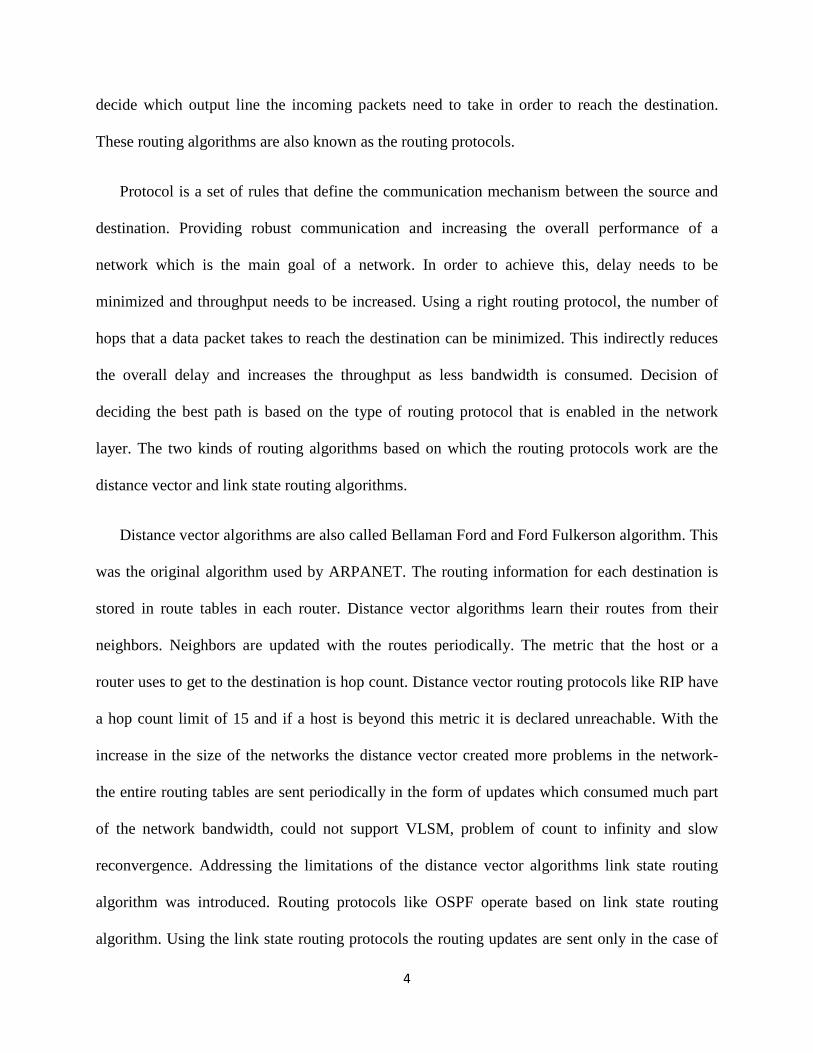
Collection of layers and protocols is called network architecture. In order to reduce the
complexity in network design and operation, networks are implemented in a stack of layers [4].
Network architecture is represented with two reference models, one OSI model and other TCP/IP
model. TCP/IP model was a successor to OSI model which promised reliable means of
communication. TCP/IP is a set of protocols in each layer using which the hosts communicate on
internet. Each layer in the stack provides services to its above layer. Following figure shows the
TCP/IP model.
Fig 1.1: TCP/IP model
Application Layer:
The application layer is the interactive layer using which the users get the required information
and it also presents the data to the end users in a readable format. Application layer includes the
protocols like TELNET, SMTP, FTP, HTTP. All these protocols allow users to acquire the
information, transfer the information and remotely access other hosts.
The presentation and session layers of OSI model were taken off from TCP/IP model.
Application Layer
Transport Layer
Network Layer
Link Layer

3
Transport Layer:
This layer lies above the network layer. The two protocols that are used in this layer are TCP and
UDP. Any application layer protocol depends on either of the protocols for communication. TCP
layer provides host to host connectivity. TCP is called connection oriented protocol and is highly
reliable. Before the transfer of data, host initiates a TCP connection with the destination using
TCP handshake mechanism. After successful connection setup the data transfer takes place. TCP
layer fragments the TCP segments based on negotiated maximum segment size during the
session establishment. During the data transfer if there are any drops in the data segments they
are retransmitted back. TCP uses acknowledgements to ensure that data is delivered with no
drops, sequence numbers are used to reassemble the fragmented segments and checksum to
validate the received segments. Protocols that use TCP are HTTP, FTP, SMTP and so on. On the
other hand UDP is a connectionless protocol which is used in the case of real time data transfers.
UDP does not provide any services provided by TCP.
Network or Internet Layer:
This layer is common in both the OSI and TCP/IP model. The core job of this layer is to route
the data packets from source to destination and this depends on the source and destination IP
addresses. As the TCP segments are passed to the network layer, it encapsulates the TCP
segments with IP header which has the source address, destination address, checksum and TTL.
It is the IP layer that defines the path and steers the data packets in right direction to the
destination. IP in a network layer is a routed protocol which carries the IP data packets and these
IP packets are routed using routing algorithms. The routing algorithms that are used in this layer
4
decide which output line the incoming packets need to take in order to reach the destination.
These routing algorithms are also known as the routing protocols.
Protocol is a set of rules that define the communication mechanism between the source and
destination. Providing robust communication and increasing the overall performance of a
network which is the main goal of a network. In order to achieve this, delay needs to be
minimized and throughput needs to be increased. Using a right routing protocol, the number of
hops that a data packet takes to reach the destination can be minimized. This indirectly reduces
the overall delay and increases the throughput as less bandwidth is consumed. Decision of
deciding the best path is based on the type of routing protocol that is enabled in the network
layer. The two kinds of routing algorithms based on which the routing protocols work are the
distance vector and link state routing algorithms.
Distance vector algorithms are also called Bellaman Ford and Ford Fulkerson algorithm. This
was the original algorithm used by ARPANET. The routing information for each destination is
stored in route tables in each router. Distance vector algorithms learn their routes from their
neighbors. Neighbors are updated with the routes periodically. The metric that the host or a
router uses to get to the destination is hop count. Distance vector routing protocols like RIP have
a hop count limit of 15 and if a host is beyond this metric it is declared unreachable. With the
increase in the size of the networks the distance vector created more problems in the network-
the entire routing tables are sent periodically in the form of updates which consumed much part
of the network bandwidth, could not support VLSM, problem of count to infinity and slow
reconvergence. Addressing the limitations of the distance vector algorithms link state routing
algorithm was introduced. Routing protocols like OSPF operate based on link state routing
algorithm. Using the link state routing protocols the routing updates are sent only in the case of
5
any changes in the network and only the changed routes are advertised. Thus the bandwidth is
utilized efficiently. The other advantages of link state routing protocols are each router has the
view of entire network; each router has the shortest path to each destination, supports VLSM and
provides fast reconvergence.
Apart from these factors the network layer provides other services such as implementation of
security features and Quality of Service.
Link layer:
Link layer in TCP/IP model combines the functions of both the data link layer and physical
layer. Important functions like ARP, framing, error checking in the data received are done in this
layer. ARP is a process of acquiring the MAC address based on IP address. As the packets are
received from the network layer the link layer encapsulates the packets with the link layer header
which holds the source MAC, destination MAC and checksum. Destination MAC is acquired
from the ARP table which has the MAC address entries that re mapped with respective IP
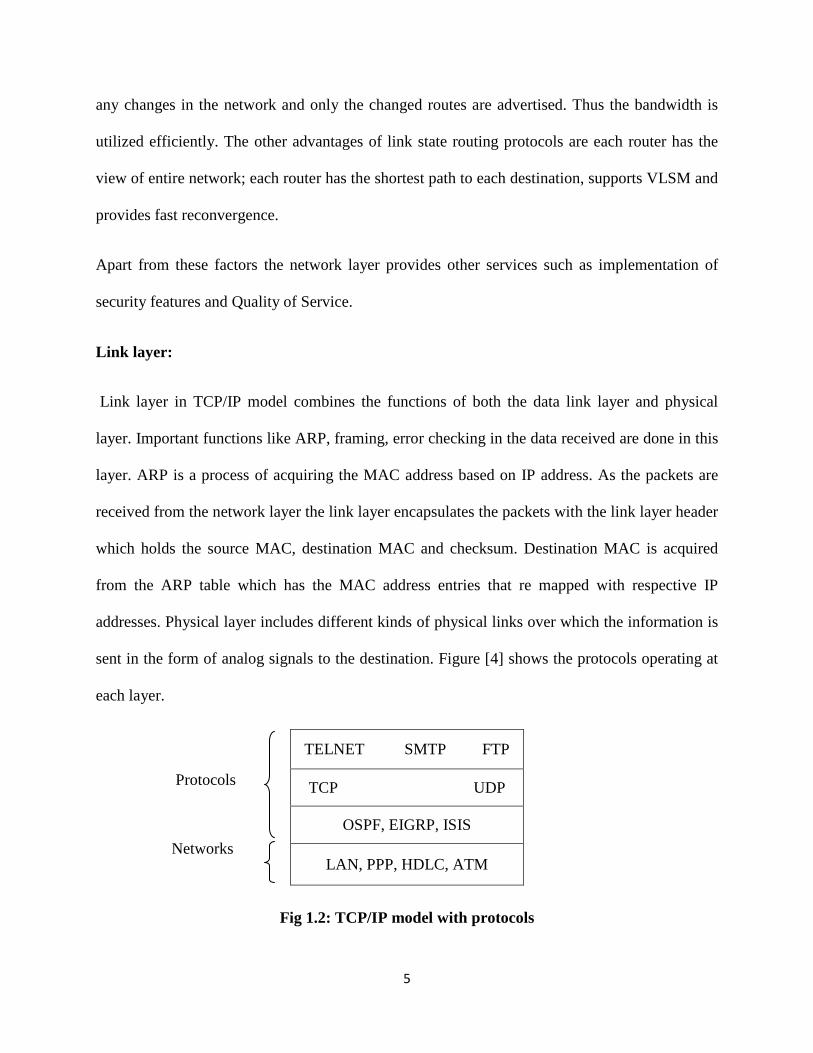
addresses. Physical layer includes different kinds of physical links over which the information is
sent in the form of analog signals to the destination. Figure [4] shows the protocols operating at
each layer.
Protocols
Networks
Fig 1.2: TCP/IP model with protocols
TELNET SMTP FTP
TCP UDP
OSPF, EIGRP, ISIS
LAN, PPP, HDLC, ATM
6
1.2 Performance issues:
Till now, the functional aspects of a network have been discussed and now the performance and
the factors that affect the performance will be discussed. Performance of a network determines
effectiveness, reliability and robustness of a network. Performance depends on two factors, one
the bandwidth and second delay.
Bandwidth is a measure of number of bits that can be transmitted in a particular amount of
time. Performance of a system is measured as the throughput. Throughput is the number of bits
that are actually transmitted per second. For example a service provider might be providing a
total bandwidth of 6 Mbps but the actual throughput would be only 4 Mbps. So throughput can
be expressed as percentage of bandwidth. On the other hand delay is the time that a message or
data takes to move from one end to the other end. Delay in a network is expressed as summation
of propagation delay, transmit delay and queuing delay.
Total Delay = Propagation delay + Transmit delay + Queuing delay
Propagation delay is the time taken by data to travel a distance over a medium with the
speed of light (D/S; D is distance and S is the speed of light, 2.3*10^8 m/s for cable, 2.0*10^8
m/s for fibre). Transmit delay is the delay that a packet of a particular size takes to travel over a
network with particular bandwidth (PS/BW; PS- packet size, BW- bandwidth). Queuing delay is
the delay seen in the networking devices to send the packets from the input queue to the output
queue. Usually queuing delay is the amount of time that the packets lie in the queue for being
processed.
7
1.2.1 Current issues or problems:
Over the years good amount of research has been done in order to minimize the delay and
increase the throughput of the networking devices. But with the increase in the network size and
growing demands of higher bandwidths a bottle neck in routers CPU utilization and memory
bandwidth has been created. In the routers most part of the CPU utilization has been spent in
moving the data packets from the interface buffers to the main memory buffers and from the
memory buffers back to the output buffers for transmission. Apart from this CPU also need to
handle network management traffic, TCP and policy based traffic. On the other hand, to meet the
high demands of link bandwidths, new technologies like Gigabit and greater Ethernet
technologies are introduced into market. Although these technologies provide more bandwidth,
they posed a serious problem with respect to the system processing capacity. Previously CPU
processing capacity was greater than network bandwidth but with the new technologies more
burden is laid on CPU in moving the data between the interfaces in a router. This thesis
addresses this problem by implementing RDMA (which is based on concept of DMA)
technology in routers in order to reduce the burden on CPU and increase the throughput.
1.3 Problem description:
In a legacy router when a packet arrives on an interface, it is processed by CPU and moved
to the respective outgoing interface. Router connected to high bandwidth links places more
burden on CPU, utilizes more memory and interface bus bandwidths. This creates a bottleneck in
their utilization and degrades the overall performance of the system. Considering these factors
there is a need to introduce required changes to the router architecture in order to address the
growing speed of network links, lessening the burden on CPU and making effective utilization of

8
available internal bandwidth in a router. This thesis work explains the proposed RDMA enabled
router architecture and proposes the operation mechanism of a RDMA technology enabled
router. In this mechanism CPU is not involved in the data forwarding operation, thus reducing
the delay and improving the performance of the router.
1.4 Organization of thesis:
In this thesis the author presents the operation of RDMA enabled router architecture. The
thesis is organized as follows, Chapter one gives an introduction to all the required networking
concepts involved in this thesis explanation. Chapter two presents the router functional aspects,
evolution of router architectures and their operation. Chapter three explains the concept of
RDMA in detail. Chapter four presents the operation of the RDMA enabled router, the operation
within a router and in between two routers is presented. Chapter five presents the mathematical
analysis of the proposed router architecture along with software router simulations and compares
the results in detail with the conventional router architecture. Chapter six concludes the thesis
work and provides some insight on the possible future work in this area.
9
CHAPTER 2
ROUTER OPERATION AND EVOLUTION OF ROUTER ARCHITECTURES
2.1 Introduction
Internet has established itself into every corner of the world. Factors like development in
the network architecture, research and development in the routing architectures, introduction of
high capacity links, and growing demand of bandwidth to support many applications have
brought a revolution in the development and progress of internet. In this chapter the author
discusses one of these factors, Router Architectures. Apart from this the basic functionality of a
router, router functional and physical components, packet handling procedures with in a router
and the different types of router architectures will be discussed.
Router is a layer three networking device implemented either in hardware or software and
whose basic functionality is routing the incoming data or control packets to the respective
outgoing interfaces. Router studies the packets, forwards and updates the packets that pass
through it. Apart from routing, the router can control the flow of packets, manipulate the traffic
flows, monitor the traffic and provide management features such as DHCP, SNMP. The
architecture of a router makes it completely different from other networking devices and makes it
a standalone device that performs many operations in a network at a very faster rate. Routers in a
network are categorized based their capability to handle the traffic load that’s passing through
them. A router used in an enterprise or a campus network passes only moderate quantities of IP
traffic, over WAN multiservice router is seen which is capable of doing both layer 2 and layer 3
10
operations between ISP and legacy voice based traffic carriers. So based on the usage and the
network types the routers are classified [13].
2.1.1 Network Types:
Different kinds of networks that define the functionalities of a router are,
i. Back bone Network.
ii. Access Network
iii. Enterprise Network.
Backbone Network:
• Backbone network connects the provider networks.
• Backbone is usually the WAN and the transmission technologies in WAN are optical.
• WAN contains edge routers and core routers.
• Links used on WAN are usually OC-48 and OC-192.
• WAN routers must be extremely reliable and ensure to operate round the clock, critical
components must be fault tolerant and line cards must be swappable.
Properties of network equipment used in WAN:
• Edge and core routers can be used in WAN.
• Equipment should be easily provisioned when and where ever they are needed.
• Both the performance and functionality of the equipment is scalable.
• Density of the design must be maximized.
• Equipment should be able to serviced, maintained and upgraded easily.
• Modular design allows changes for expansion
• WAN edge routers consolidate multiple access networks.
11
Access Network:
• Access network includes the provider network which consolidates the customer traffic
and drive into the traffic into the backbone network (WAN).
• Uplinks from the access networks to WAN are usually gigabit Ethernet or OC-12 links
(655Mbps).
Access network Equipment:
• Should support large scale and low cost aggregation of multiple physical connections to
subscribers.
• Low power consumption.
• Ability to communicate with multiple physical interfaces and layer 2 protocols.
Enterprise Networks:
• Customers, institutions, residential customers come into this category. Edge and core
routers are seen in enterprise network.
• Core routers operate in the heart of the enterprise. These have different protocol
requirement and port speeds.
Core Network Equipment:
• This equipment usually connects hundreds of edge routers, switches requiring ability to
handle gigabits-per-second traffic and terabits per second switching capability.
• Scalability and performance is required when routing and switching are involved.
• High reliability and high availability is required.
• Fault tolerance and redundancy is required.
12
• Modular designs with hot swappable modules are recommended.
2.2 Components in a router:
The components of a router can be categorized into hardware and functional components [9].
The hardware components of a general router include network interfaces, medium of
interconnecting medium, CPU and memory. The functional components of a router include the
control plane, back plane and data plane.
2.2.1 Hardware components of a router:
Network interfaces: Interface is the first layer of functionality in a router [9]. Interfaces are the
input output points of the packets in a router. These interfaces connect to the links over which the
information is transported. The bit stream from the device is modified by the network interface
into analog form before transmitting to the physical medium. Similarly the received content is
transformed back into binary form on the physical chip of the interface. The interfaces would be
part of the line cards in a router. The link layer processing, basic route lookup (based on
architecture), forwarding decisions, interface buffers are the part of line cards. Interfaces are
designed to handle different transmission media.
CPU: In a router, the major functionalities such as routing decisions, populating route tables
based on route updates, ping operations, traffic classification are done by the processor.
Involving the processor in all the decision making operations would create a bottleneck in
making the best use of the processor. Later in this chapter authors discusses how the processor is
alleviated with distributed processing in a router. Processing functionalities in a router are
usually implemented in software such that a new functionality can be added or any changes can
be made by loading a new version.
13
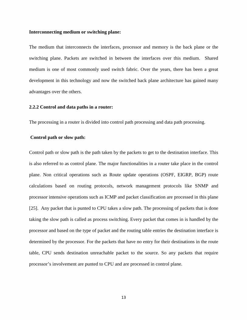
Interconnecting medium or switching plane:
The medium that interconnects the interfaces, processor and memory is the back plane or the
switching plane. Packets are switched in between the interfaces over this medium. Shared
medium is one of most commonly used switch fabric. Over the years, there has been a great
development in this technology and now the switched back plane architecture has gained many
advantages over the others.
2.2.2 Control and data paths in a router:
The processing in a router is divided into control path processing and data path processing.
Control path or slow path:
Control path or slow path is the path taken by the packets to get to the destination interface. This
is also referred to as control plane. The major functionalities in a router take place in the control
plane. Non critical operations such as Route update operations (OSPF, EIGRP, BGP) route
calculations based on routing protocols, network management protocols like SNMP and
processor intensive operations such as ICMP and packet classification are processed in this plane
[25]. Any packet that is punted to CPU takes a slow path. The processing of packets that is done
taking the slow path is called as process switching. Every packet that comes in is handled by the
processor and based on the type of packet and the routing table entries the destination interface is
determined by the processor. For the packets that have no entry for their destinations in the route
table, CPU sends destination unreachable packet to the source. So any packets that require
processor’s involvement are punted to CPU and are processed in control plane.

14
Data path or Fast path:
Data plane of a router has the capability of packet processing and forwarding the packet directly
to the outgoing interface without moving the packet to the control plane for processor’s decision.
The time intensive operations are considered under fast path. Some of the operations that are
implemented in the fast path are framing, classification, updating, encryption and queuing. Some
time consuming tasks like header validation, destination path decision making require CPU
processing and affect the performance of a router. Instead these operations can be implemented
in data plane reducing the burden on CPU and can reduce the processing time. Some protocols
like LLC, SNAP, ARP require network access and need to be implemented on a line card itself,
so they take fast path.
2.2.3 Backplane:
Router backplane consists of switch fabric which connects the control plane and data plane in a
router. The figure [2.1] shows the control and data paths in a router.
2.3 Operation of a router and packet handling procedure:
The basic operations of a router [9] can be categorized into
• Processing
• Forwarding
• Other services.
2.3.1 Packet Processing: Processing functionalities in a router include updating the route tables,
determine the best path based on the route lookups, and take an appropriate action based on
configured policies in a router.
15
CPU
Fig 2.1: Functional components of a router
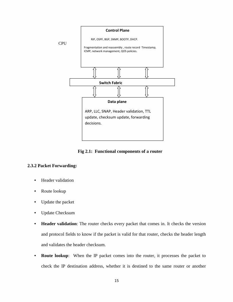
2.3.2 Packet Forwarding:
• Header validation
• Route lookup
• Update the packet
• Update Checksum
• Header validation: The router checks every packet that comes in. It checks the version
and protocol fields to know if the packet is valid for that router, checks the header length
and validates the header checksum.
• Route lookup: When the IP packet comes into the router, it processes the packet to
check the IP destination address, whether it is destined to the same router or another
Control Plane
RIP, OSPF, BGP, SNMP, BOOTP, DHCP.
Fragmentation and reassembly , route record Timestamp,
ICMP, network management, QOS policies.
Switch Fabric
Data plane
ARP, LLC, SNAP, Header validation, TTL
update, checksum update, forwarding
decisions.
16
router. This is done by parsing the route table for the IP address match and determines the
packet destination. If the packet is destined to the router then the packet is handled to the
processor. If the packet is meant for other routers, the destination address is checked with
the route table and the packet is sent back to the network through respective outgoing
interface. As the packet passes through the output interface ARP table lookup is done for
the next hop interface’s MAC address.
• Update the packet: As the packet travels over the network, there should some limiting
point so that the packets do not loop over the network. This is done by fixing the life time
of the packets using the TTL values. As the packet traverses through the network, the
TTL value is increased by 1 for every hop. The packet that is routed to the output port has
its TTL value incremented and checked for its life time. If the packet has a life time then
the packet is forwarded, if the life time exceeds then the packet is discarded to be sent out
and handled to the CPU. CPU sends an ICMP unreachable message to the source based
on the source IP address.
• Update checksum: The IP header checksum is calculated as the TTL value is updated.
As the packet passes through the intermediate routers, checksum is recalculate the
checksum and updates it. In most of the cases the checksum is incrementally updated
instead of calculating for entire header [2].
• Fragmentation: As the packet moves over the network the MTU size varies which leads
to packet fragmentation. Fragmented packets of the same flow are given same identifier
and this is done by the processor of the router.

17
2.3.3 Other Services:
The functions other than routing include the traffic prioritization, QOS and management
operations. IP packet has TOS (Type of service) field which are used by the router to determine
if the packet requires any special treatment.
2.4 Router Architectures:
With the growth in the traffic over the network the demand for efficient, multi gigabit and
terabit networking technologies increased. Consistent demands for new and powerful routers in
the network lead to the research and development of the new router architectures. The goal of
bringing out high throughput routers was achieved by identifying the critical tasks and special
modules in a router and arranging them properly to bring out required performance [9].
Types of router architectures:
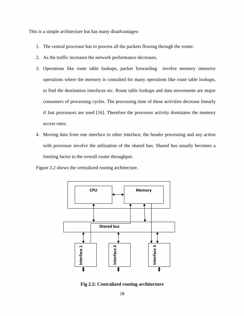
2.4.1- 1st generation router architecture: Centralized Routing Architectures:-
In this architecture a single general purpose processor is connected to multiple interfaces
using shared bus. In this architecture the processor does all operations on a packet.
Shared bus interconnects all the interfaces. As the packet arrives on the interface it is sent to the
processor for processing. Interfaces do not have any special hardware for packet processing and
forwarding. The packet traverses twice over the shared bus, first when the packet is buffered into
the memory for processing and second when the packet needs to routed back to respective
outgoing interface from the memory. The advantage of this architecture is simple to implement
and low cost.
18
This is a simple architecture but has many disadvantages-
1. The central processor has to process all the packets flowing through the router.
2. As the traffic increases the network performance decreases.
3. Operations like route table lookups, packet forwarding involve memory intensive
operations where the memory is consulted for many operations like route table lookups,
to find the destination interfaces etc. Route table lookups and data movements are major
consumers of processing cycles. The processing time of these activities decrease linearly
if fast processors are used [16]. Therefore the processor activity dominates the memory
access rates.
4. Moving data from one interface to other interface, the header processing and any action
with processor involve the utilization of the shared bus. Shared bus usually becomes a
limiting factor to the overall router throughput.
Figure 2.2 shows the centralized routing architecture.
Fig 2.2: Centralized routing architecture
Shared bus
Inte
rfa
ce 1
Inte
rfa
ce 2
Inte
rfa
ce 3
CPU Memory
19
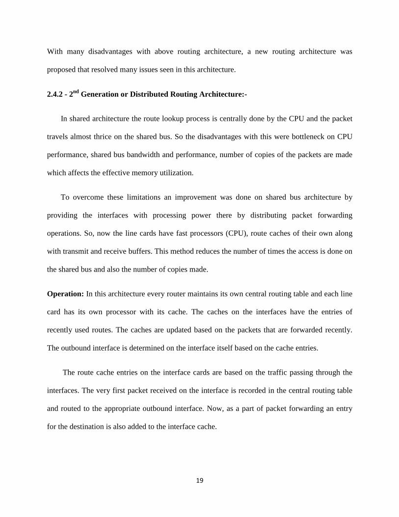
With many disadvantages with above routing architecture, a new routing architecture was
proposed that resolved many issues seen in this architecture.
2.4.2 - 2nd Generation or Distributed Routing Architecture:-
In shared architecture the route lookup process is centrally done by the CPU and the packet
travels almost thrice on the shared bus. So the disadvantages with this were bottleneck on CPU
performance, shared bus bandwidth and performance, number of copies of the packets are made
which affects the effective memory utilization.
To overcome these limitations an improvement was done on shared bus architecture by
providing the interfaces with processing power there by distributing packet forwarding
operations. So, now the line cards have fast processors (CPU), route caches of their own along
with transmit and receive buffers. This method reduces the number of times the access is done on
the shared bus and also the number of copies made.
Operation: In this architecture every router maintains its own central routing table and each line
card has its own processor with its cache. The caches on the interfaces have the entries of
recently used routes. The caches are updated based on the packets that are forwarded recently.
The outbound interface is determined on the interface itself based on the cache entries.
The route cache entries on the interface cards are based on the traffic passing through the
interfaces. The very first packet received on the interface is recorded in the central routing table
and routed to the appropriate outbound interface. Now, as a part of packet forwarding an entry
for the destination is also added to the interface cache.
20
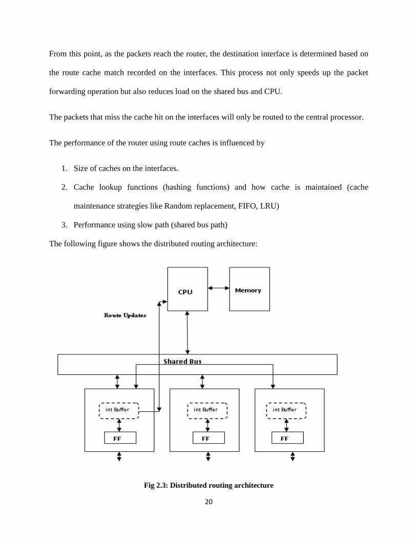
From this point, as the packets reach the router, the destination interface is determined based on
the route cache match recorded on the interfaces. This process not only speeds up the packet
forwarding operation but also reduces load on the shared bus and CPU.
The packets that miss the cache hit on the interfaces will only be routed to the central processor.
The performance of the router using route caches is influenced by
1. Size of caches on the interfaces.
2. Cache lookup functions (hashing functions) and how cache is maintained (cache
maintenance strategies like Random replacement, FIFO, LRU)
3. Performance using slow path (shared bus path)
The following figure shows the distributed routing architecture:
Fig 2.3: Distributed routing architecture
21
Although this architecture has some advantages, there were even some limitations.
The route cache present along with CPU on the interfaces has some limitations.
1. If a route is not found in the cache then the next lookup would be the central routing table
maintained by CPU of the router. So, in a network where dynamic changes in the
topology are seen, the route cache changes frequently and the route lookup again takes
the slow path which is in many orders of magnitude lower than the fast path.
2. Even here the shared bus is a bottleneck.
3. In case of large hits the route caches are not sufficient. Even the main table lookups in the
case of high traffic networks is a disadvantage.
2.5.3 - 3rd Generation router architecture or switched router architecture:
To overcome the limitations of the second generation architectures, some of the architectures
have been proposed with changes in the architecture.
1. Forwarding database was introduced on the interfaces which would represent the entire
routing table (present with CPU). This would eliminate route caches, there by knocking
out the slow path. This would benefit the performance, network resilience and
functionality especially in the case of large and complex networks with dynamic flows.
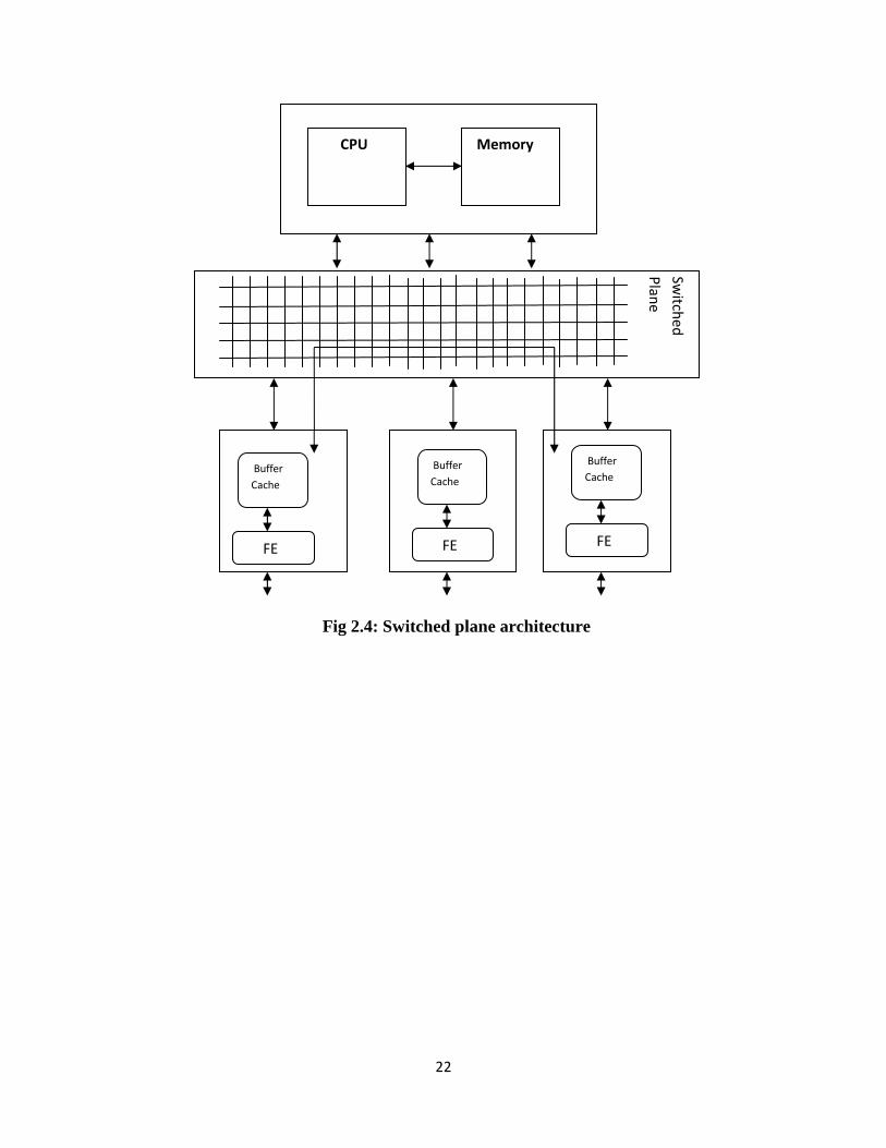
2. Other limitation with shared and distributed architecture was using shared bus. In
network during high traffic periods with more number of route cache misses, the number
of times the slow path is considered increases. With the increase in the use of slow path
again the shared bus becomes the critical resource. To overcome this disadvantage
switched fabric was introduced. In a router a switch fabric transfers of packets from input
to output modules with no limitations. The figure 2.4 shows shared fabric architecture:
22
Fig 2.4: Switched plane architecture
Sw
itche
d
Pla
ne
CPU Memory
Buffer
Cache
FE
Buffer
Cache
FE
Buffer
Cache
FE

23
CHAPTER 3
RDMA
3.1 Introduction to RDMA:
The advances in computing and networking technology always open a new problem thus
providing a scope for good research and finally lead to a new development. With the
advancement of the storage and information technology one of the major problems that
concerned the field of networking is the I/O bottleneck. High host processing overhead with the
movement of data to and from the network interface under high speed conditions is referred to as
I/O bottleneck [3]. In a network I/O processing the overhead results from data movement
operations especially copying, and moving the data several times over the data and memory bus.
More over in the case of TCP/IP data is moved across the specified bus technologies several
times, this is the reason for not using TCP/IP for high speed transfers. So, instead a special
technology called RDMA (Remote Direct Memory Access) has been used. RDMA is a process
of moving the data from one system to the other without the involvement of the processor.
RDMA can also be elaborated as a technology where the application which controls the network
adapter steers the data directly into and out of the application buffers.
Optimum research has been done in the field of networks and operations to improve the
overall speed of processing the data over the network. In the case of routers, most part of the
CPU utilization is used for packet processing sent from the control plane to the processor.
Research has proved that improvement of just the CPU processing speed does not increase the
overall performance of the system [15]. Apart from CPU processing speed the memory
24
bandwidth needs to be increased. Over the years good work has been done to improve the CPU
processing speed than compared to the memory bus bandwidth, so the available limited memory
bus bandwidth also becomes a scaling factor to improve the overall performance of system.
Reducing the burden of the packet processing to any extent by the CPU, making it available for
other processes would not only improve the performance of the system but would also increase
the available memory bus bandwidth. An emerging technology like RDMA promises to achieve
these goals. The basic philosophy of RDMA comes from DMA.
3.2 DMA:
DMA is a process of offloading the processor by moving the function of data transfer to the
device controller, which is responsible in moving the data to and from memory without the
involvement of the processor. With DMA, CPU is freed with the overhead of moving the data
from the memory to the I/O devices. When the CPU initiates the DMA controller for the data
transfer, a block of memory is copied from one device (memory) to the other (I/O memory or
cache). This mechanism of not involving the processor in the data movement and moving the
data directly from memory of one system to other with intermediate copies is called zero copy
mechanism. The process of DMA transfer takes place in three steps [5].
1. The processor initiates the DMA by providing it the identity of the device, the operation
that has to be performed on the device, memory address (the beginning and the end) of
the data that needs to be transferred and the size (number of bytes) to be transferred.
2. The DMA controller arbitrates for the bus and starts the process of data transfer upon the
availability of data. The DMA controller becomes a unit on the bus that can initiate the
bus requests and directs the data read and write between the cache and the memory.
25
3. Upon the completion of the data transfer the controller interrupts the processor which
examines the memory if the transfer operation has been done successfully.
Since the operational speed of the peripheral devices is significantly slower than the system
RAM, the copy mechanism between the memory and peripheral devices would involve CPU
unavailable for other processes. So, the involvement of DMA would improve the performance
of CPU to a great extent, thereby improving the overall performance of the system. DMA can
also be used to offload the expensive memory operations and the process of DMA is usually
implemented as a separate hardware.
3.3 Overview of Operation of RDMA:
RDMA eliminates the data copy operations and reduces the latency in moving the data by
allowing the applications that are present locally to read and write data into a remote system’s
memory with minimal demands on CPU processing overhead and memory bus bandwidth [1].
RDMA provides seven data transfer operations but with an exception in the case of read
operation, which generates only one RDMA message. These operations include (i) Send, (ii)
Send with Invalidate, (iii) Send with Solicited Event, (iv) Send with Solicited Event and
Invalidate, (v) Remote Direct Memory Access Write, (vi) Remote Direct Memory Access Read
and (vii) Terminate.
i. Send: Send operation uses the send message in transferring the data from the data
source’s buffer to the data sink’s buffer that is not advertised. Send message uses
untagged buffer model to transfer the data to the data sink’s untagged buffer.
ii. Send with Invalidate: Send with Invalidate operation uses a send with invalidate
message to transfer the data from the source to the data sink’s unadvertised buffer. This
26
operation is quite similar to send message but includes an additional STag field in the
Send with Invalidate message. Once the message is delivered at the data sink the buffer
(STag) will no longer be available for access to the local peer until the ULP
(application) re-validates the access or advertises the buffer.
iii. Send with Solicited Event: This operation is similar to the send operation with an
addition of generating an event upon the successful delivery of the message. The
generation of event depends upon how the recipient is configured.
iv. Send with Solicited Event and Invalidate: This operation is similar to send with
invalidate with an addition of generating an event upon the successful delivery of the
message and if the recipient is configured to generate an event.
v. Remote Direct Memory Access Write: RDMA write operation uses the RDMA write
message to write the data from data source into the advertised buffer of the data sink.
vi. The remote peer which in this case the data sink enables its Tagged Buffer for access by
the local peer (data source) by advertising its buffer size, location and Steering Tag
using ULP specific mechanism. RDMA write uses DDP tagged buffer model to transfer
the data to advertised buffer of data sink. The advertised STag remains valid until the
ULP at the data sink or the data source invalidates by exchanging Send with Invalidate
or Send with Solicited Event and Invalidate message.
vii. Remote Direct Memory Access Read: RDMA write operation is used to transfer the
data from the Tagged buffer of the data source to the tagged buffer of the data sink. In
this operation the ULP of the data source enables its tagged buffer for access by
advertising the buffer size, location (tagged offset) and STag to the data sink. The read
operation is a single request message and uses DDP untagged buffer model to deliver the
27
message to RDMA read request queue of the source. The RDMA read response from the
data source is delivered to data sink’s tagged buffer using tagged buffer model. This
operation does not involve the ULP at the data source. ULP is usually a specific
application and the ULP advertisement mechanism is left to the designer of the
application. The data source tag and the data sink remain valid until the ULP at the both
ends invalidates it by sending the send with invalidate or send with solicited event and
invalidate message.
viii. Terminate: Terminate message is used for terminating the connection. DDP untagged
buffer model is used to send the terminate message.
3.4 General Terms:
Data Source: The peer that sends the data is known as data source. Data Source is also known as
local peer. Data source has the capability of both sending and receiving the RDMA/DDP
messages to transfer the data payload.
Data Sink: The peer that receives the data from the data source is called the data sink. Data sink
is also known as remote peer. Data sink has the capability of sending and receiving the
RDMA/DDP messages to transfer the data payload.
Advertisement: Advertisement is a method used by a node if it wants the remote peer know
about its RDMA buffer. So here the local peer lets the remote peer know about the available
RDMA buffer using the tagged buffer identifiers such as STag, buffer length and base address.
Tagged buffer: The buffer that is advertised to the remote peer by exchanging the STag, Target
offset and length.

28
Untagged buffer: The buffer that is not advertised to the remote peer. Untagged buffer is used
in the data transfer techniques like untagged buffer model. Control messages like RDMA read,
send and connection termination requests are sent using the untagged buffer type messages.
STag(Steering tag): The tagged buffer at a node is identified by using an identifier called STag.
Tagged Buffer Model: Data transfer model that is used to transfer the tagged buffers from one
node to another is called tagged buffer model.
Untagged buffer Model: Data transfer model that is used to send the untagged buffers from one
node to another node.
Tagged Offset: The range or the offset within a tagged buffer on a peer is tagged offset.
Event: A procedure used by the RDMAP layer to indicate the ULP about the completion of the
transfer. This is also generated if the RDMAP requires any attention from the ULP.
ULP: Upper layer protocol is the protocol layer above a specified layer and for RDMA/DDP the
ULP protocol would be the operating system or any specific application, proprietary device.
ULP buffer: RDMAP layer owns a buffer and is advertised to the remote peer as tagged buffer
or untagged buffer.
Data delivery: The process of informing the ULP that the data or message is available for use is
called delivery.
Graceful teardown: Method of terminating a stream such that all the messages that are in
progress and in pending are allowed to be complete successfully before closing the stream.
29
Abortive teardown: Method of closing the stream without completing the pending and in
progress messages.
Stream: Sequence of messages is known as a stream and the stream is defined by the lower layer
protocol. Stream can also be a sequence of messages with common identifier.
3.5 RDMAP layering:
Layering of the RDMAP stack defines the relationship between each layer with its upper layer
protocol and lower layer protocol. The RDMA layer converts the RDMA messages as DDP
requests and sends them to the DDP layer. As the DDP layer receives these requests, it fragments
the DDP segments handled by the RDMA layer based on buffer length advertised by the remote
peer. These fragmented DDP segments are handled to the MPA layer where the header and CRC
fields are appended; the fragments from this point are called as FPDU (framed protocol data
units). These FPDUs are handled to the TCP layer which further fragments the based on the
negotiated maximum segment size value. After fragmenting into TCP segments each segment is
appended with a header and handed over to the IP layer. In the IP layer the IP header is appended
and sent to the lower layers for transmission. On the receiving end, the TCP layer reassembles
the fragments based on the sequence numbers and are handed over to the DDP layer. At this
point the FPDUs remain as they are as they indicate the starting and end points of the DDP
header. The buffer information present in the DDP header is used to write the data directly to the
respective application buffer without involving the RDMA layer.
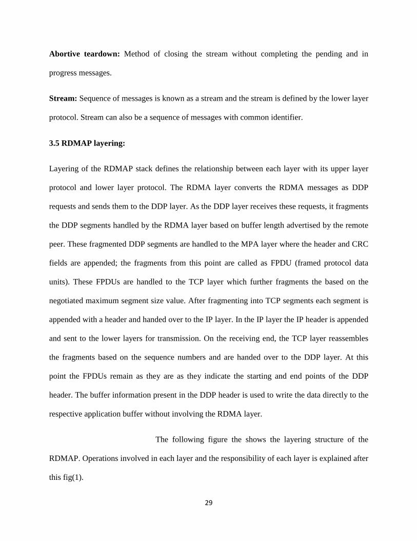
The following figure the shows the layering structure of the
RDMAP. Operations involved in each layer and the responsibility of each layer is explained after
this fig(1).
30
Upper Layer Protocol (ULP) or Application
RDMAP
DDP
MPA
TCP/IP
IP
Fig 3.1: RDMAP layering
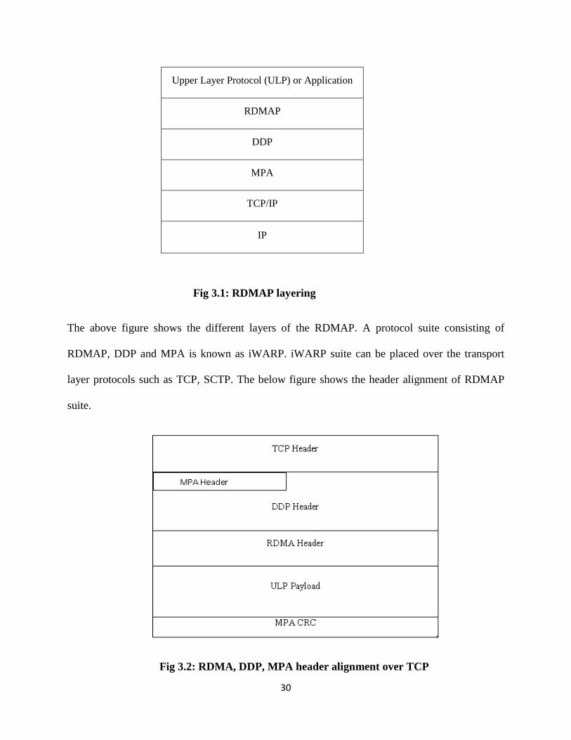
The above figure shows the different layers of the RDMAP. A protocol suite consisting of
RDMAP, DDP and MPA is known as iWARP. iWARP suite can be placed over the transport
layer protocols such as TCP, SCTP. The below figure shows the header alignment of RDMAP
suite.
Fig 3.2: RDMA, DDP, MPA header alignment over TCP
31
3.5.1 Explanation:
3.5.1.1 RDMAP: RDMA is a process of connecting to the remote host and accessing the
required data from remote host’s buffer. In this process RNIC is engaged in the remote
system, thus relieving the CPU from this job. RDMA is a protocol that is supported and used
over the wire to transfer the upper layer protocol’s data from the source to the destination.
The RDMA operation includes the transfer of sequence of RDMA messages including the
control messages from the source to the destination’s buffer. RDMA operations will include,
RDMA write, RDMA read, send with solicited event, send with unsolicited event and
terminate. These operations of RDMA will be explained in the following section in detail.
RDMA layer handles the RDMA messages to the DDP layer. RDMAP also interacts with the
upper layer protocol (ULP) at the data source and the data sink. RDMAP provides the ULP
access regarding some operations such as Send, send with solicited event, send with
invalidate, send with solicited event and invalidate, RDMA write, RDMA read.
3.5.1.2 ULP interaction with RDMAP layer in case of Send operation:
At Data Source:
In the case of Send operation the ULP which might be any application or any specific
device issues the RDMAP layer the following: 1. ULP message size, 2.ULP message, 3.Valid
type of send operation which indicates if an event is to be generated at the data sink, 4.
Indication that would represent the completion operation.
At Data Sink:
32
In the case of Send operation at the data sink, the RDMAP passes the ULP the following:
1. ULP message size, 2. ULP message, 3. An event is generated as discussed above, 4. In the
case of completion with an error, the RDMAP layer sends the error information to the ULP
and a termination message is sent to the data source’s RDMAP layer. Upon receiving the
error information, it is passed to the ULP.
3.5.1.3 ULP interaction with RDMAP layer in case of Write operation:
At Data Source:
In the case of write operation the ULP which might be any application or any specific
device issues the RDMAP layer the following: 1. ULP message size, 2.ULP message, 3. Data
Sink’s buffer location (STag), Data Sink’s tagged buffer offset, 4. Indication that would
represent the completion operation.
At Data Sink:
At the data sink upon the completion of write message, the RDMAP does not handle the
RDMA write to the ULP and places the message directly into the ULP’s buffer with RDMA
write operation. In the case of RDMA write with an error, the error will be reported to the
ULP at data sink and a termination message would be sent to the data source’s RDMAP
layer. Upon receiving the error message at the source the RDMAP layer would pass this
message to the ULP.
3.5.1.4 ULP interaction with RDMAP layer in case of Read operation:
At Data Sink:
In the case of read operation the ULP at the data sink is responsible to provide the 1.
Message length, 2. Data source’s STag, 3. Data sink’s STag, 4. Data source’s tagged offset
and data sink’s tagged offset
At Data source:
The ULP is not informed with any information in the case of RDMA read except if an error
is encountered.
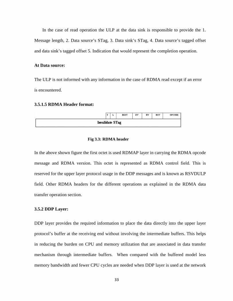
3.5.1.5 RDMA Header format:
In the above shown figure the first octet is used RDMAP layer in carrying the RDMA opcode
message and RDMA version. This octet is represented as RDMA control field. This is
reserved for the upper layer protocol usage in the DDP messages and is known as RSVDULP
field. Other RDMA headers for the different operations as explained in the RDMA data
transfer operation section.
3.5.2 DDP Layer:
DDP layer provides the required information to p
protocol’s buffer at the receiving end without involving the intermediate buffers. This helps
in reducing the burden on CPU and memory utilization that are associated in data transfer
mechanism through intermedia
memory bandwidth and fewer CPU cycles are needed when DDP layer is used at the network
33
In the case of read operation the ULP at the data sink is responsible to provide the 1.
Message length, 2. Data source’s STag, 3. Data sink’s STag, 4. Data source’s tagged offset
5. Indication that would represent the completion operation.
The ULP is not informed with any information in the case of RDMA read except if an error
RDMA Header format:
Fig 3.3: RDMA header
In the above shown figure the first octet is used RDMAP layer in carrying the RDMA opcode
message and RDMA version. This octet is represented as RDMA control field. This is
or the upper layer protocol usage in the DDP messages and is known as RSVDULP
field. Other RDMA headers for the different operations as explained in the RDMA data
DDP layer provides the required information to place the data directly into the upper layer
protocol’s buffer at the receiving end without involving the intermediate buffers. This helps
in reducing the burden on CPU and memory utilization that are associated in data transfer
mechanism through intermediate buffers. When compared with the buffered model less
memory bandwidth and fewer CPU cycles are needed when DDP layer is used at the network
In the case of read operation the ULP at the data sink is responsible to provide the 1.
Message length, 2. Data source’s STag, 3. Data sink’s STag, 4. Data source’s tagged offset
5. Indication that would represent the completion operation.
The ULP is not informed with any information in the case of RDMA read except if an error
In the above shown figure the first octet is used RDMAP layer in carrying the RDMA opcode
message and RDMA version. This octet is represented as RDMA control field. This is
or the upper layer protocol usage in the DDP messages and is known as RSVDULP
field. Other RDMA headers for the different operations as explained in the RDMA data
lace the data directly into the upper layer
protocol’s buffer at the receiving end without involving the intermediate buffers. This helps
in reducing the burden on CPU and memory utilization that are associated in data transfer
te buffers. When compared with the buffered model less
memory bandwidth and fewer CPU cycles are needed when DDP layer is used at the network
34
interface. DDP layer which is layered below the RDMAP layer uses identifier of a tagged
buffer on anode (STag) and Tagged Offset for RDMA write and RDMA read response
messages. DDP layer inserts the RSVDULP field value which is given by the RDMAP layer.
DDP provides proper sequential delivery semantics for the messages. DDP provides a facility
to reassemble the incoming DDP segments before they are delivered to the application or the
ULP. DDP supports two buffer transfer models, 1. Tagged buffer transfer model, 2.
Untagged buffer transfer model.
3.5.2.1 Tagged Buffer Transfer model:
In this model the data sink advertises a Stag which is used as an identifier for the ULP
(application specific) buffers to the data source. Upon receiving the steering tag the source
determines which tagged buffer will be utilized for the obtained DDP message. The ULP of
the data sink uses its own specific mechanism to advertise the buffer for the data transfer to
take place. The buffer advertisement mechanism is left to the application designer. Any
random offset address in the obtained tagged buffer can be used to start DDP message. One
ULP advertisement can accomplish the task of multiple DDP messages to acquire the data
from the tagged buffer.
3.5.2.2 Untagged buffer model:
Data transfer in this model can start without the need of data sink to advertise the buffer
information. The received data is queued in the order they are received. If the data source
sends the payload that the data sink cannot accommodate in the receive buffer an error is
generated. The data sink specifies the order in which it utilizes the received DDP messages.
It is specified that flow control mechanism needs to be presented by the ULP so that the DDP

35
messages are not dropped if they are received without any knowledge of the buffer
information and an error is not reported. This model demands a ULP receive buffer for each
and every DDP message with no buffer information is received.
Apart from the above information, the DDP offers properly ordered and reliable delivery of
DDP messages. Even if the messages arrive out of order the messages are placed correctly
into their associated buffer. When all the DDP messages are successfully received and placed
in ULP buffer, the data payload is presented to the ULP.
3.5.2.3 DDP :
Fig 3.4: DDP control field header
In the above header T bit is the tagged bit, L is the Last flag bit, RSVD is the reserved bit and
DV is DDP version bit.
Tagged bit: This bit is used to specify if this is a tagged buffer or an untagged buffer for the
ULP information. If T bit is set to ‘1’ represents tagged buffer and T bit is set to ‘0’
represents untagged buffer.
Last bit: This flag bit is used to indicate the last DDP segment in the series of DDP
segments. Only the last DDP segment has this bit set to 1. If a node receives a DDP segment
with last bit set to 1, then the DDP messages placed in the ULP buffer are presented to the
ULP. If the bit in the L field is zero it represents an intermediate DDP segment.
RSVD: This bit is not used and s reserved for future use. This field is not checked when the
DDP segment is received.
T L RSVD DV

36
DDP version: The value in this field is set to zero as per the specifications (RDMA
consortium). The value specified in this field is constant for all the DDP segments.
3.5.3 MPA layer: RDMAP layer handles the requests to the DDP layer which fragments into
DDP segments and present them to the MPA layer. MPA layer adds the CRC and header
information which indicate the end of the DDP segments. From this point the segments are
known as the FPDUs. These FPDUs are presented to the TCP layer, which further fragments
them to the TCP segments and makes sure that each TCP segment holds a FPDU. On the
receiving end, after TCP reassembles the segments into FPDUs, MPA layer validates and
removes the header and presents the DDP segments to the DDP layer.
3.5.4 TCP layer: TCP is a reliable transport protocol which is used in RDMA for reliable
connections. In the case of RDMA operation, before the stream initialization TCP connection
is established with the destination. The maximum segment size which is based on the
configured MTU size in the lower layers is negotiated with the destination during session
establishment. TCP has different control mechanisms like flow control, error control
mechanisms to control the data flow over the network. The MSS (maximum segment size)
that TCP negotiates is presented by TCP to the DDP layer so that more time is not spent in
fragmentation at each layer and DDP can segment the information such that it is compatible
as the encapsulated information passes to the lower layers. After TCP segmentation, it
presents the TCP segments to the IP layer for routing.
3.5.5 RDMA data transfer mechanisms:
3.5.5.1 RDMA write: This operation does not have specific RDMAP header. RDMAP
passes the RDMA control field information to the DDP layer. The write header is described

37
by the DDP headers of the associated DDP segments. The following shows the DDP format
segment for RDMA write.
Fig 3.4: RDMA write message, DDP segment format
This is used by the RDMA source to transfer data to a previously advertised buffer at the data
target. The message is tagged with a DDP header as shown above. In the above figure the tagged
offset can be any value other that zero. Source initiates the write operation. At the source
discontinuous blocks can be the source of the information for RDMA write and source has the
capability to combine all these blocks into a single one so that it can write as a single write at the
remote peer. DDP tagged buffer model is used for RDMA write. The order of the RDMA write
given by the ULP and to the DDP layer is preserved. A single RDMA write can write into a
single buffer and at the remote peer a valid RDMA write is not sent reported to ULP and invalid
RDMA write is reported to the ULP and an error is generated.
3.5.5.2 RDMA read: RDMA read is a combination of two commands, RDMA read request and
RDMA read response.
Read request: This message is used by the remote peer to transfer the data from a previously
advertised buffer at source to tagged buffer at the remote peer. Untagged buffer is used for read
request. At the local peer the RDMA layer processes the request and valid request header is sent
DDP control RDMA control
Data sink Stag
Data Sink Tagged Offset
RDMA write ULP payload
38
to the ULP. RDMA read request references the read request queue. The order of the RDMA read
requests given by the ULP and to the DDP layer is preserved. After the source validating the
RDMA read request it responses back with valid read response. If the local peer receives
RDMA read request size of zero in its header, then it responses back with zero length RDMA
read response. If an invalid read request is received at the local peer it is presented to the ULP
and an error is generated.
Read response: This is used by the local peer to respond to a valid read request. This uses
tagged buffer model. In this process without involvement of the ULP the requested information
of the local peer’s tagged buffer is transferred to the data sink. At the remote peer the RDMA
response must be passed to the ULP. The order of the delivery of the messages is preserved. At
the local peer sufficient number of untagged buffers must be available on read request queue in
order to support the read responses. If the remote peer wishes to get or read more than one
tagged buffer information, then it uses multiple read request messages.
3.5.5.3 RDMA send: This uses DDP untagged buffer model, where the DDP marks the
messages as untagged. Each untagged message is mapped to one untagged buffer. Message size
sent by the ULP may be less than or equal to the consumed untagged buffer. RDMAP
communicates the size of data written to the untagged buffer. If the message size is larger than
data sink’s untagged buffer an error is generated. The order of message delivery is preserved.
RDMA local peer can choose discontinuous blocks for the sending the data and in this case all
the data blocks can be combined to a single block and send as a single data type to the data sink.
3.5.5.4 Terminate: This message carries error related information from the local peer to the
remote peer and closes all the pending or further connections in the underlying DDP stream.

39
RDMAP passes the terminate message to the ULP. This message uses DDP untagged buffer
model.
3.5.5.5 RDMA stream initialization: Soon after the TCP connection establishment the RDMA
operation is enabled. After the lower layer protocol’s initialization the ULP or application or
preconfigured device transitions the LLP stream into RDMA mode. It’s the responsibility of the
ULP at the local peer to negotiate the number of outstanding RDMA read requests per direction
per stream. This is negotiated by the ULP with the RDMA layer at the local per. Negotiation
between the remote peer’s ULP is also done by the local peer about the maximum number of
outstanding RDMA read requests per direction per stream. It is suggestible to limit the number of
requests per stream and per direction by setting a maximum limit.
3.5.5.6 RDMA stream teardown: Terminating the connection between the peers is known as
stream teardown. This stream teardown is expressed as graceful teardown, abortive termination,
LLP abortive termination. In graceful termination the ULP or application on either of the sides
issues a message for graceful termination. Method of terminating a stream such that all the
messages that are in progress and in pending are allowed to be complete successfully before
closing the stream is called graceful termination. Abortive termination is invoked because of any
error reported by the LLP. When this happens, a message is sent to the ULP and also the
terminate message to the remote peer’s RDMAP indicating the termination of session. The
pending and ongoing streams will also be terminated because of abortive termination. Data loss
may also be experienced in the case of abortive termination. It is desired that the peers must do a
graceful teardown upon receiving the abortive teardown message so that the pending requests are
processed before terminating the session, which might save the time and resources.
40
3.5.5.7 RDMA error management: Errors usually occur because of poor programming in the
ULP or application which is responsible for the stream management semantics for the RDMAP
stream. In the case of any error, if RDMAP stream issues a stream teardown and if the LLP is not
able to perform independent stream teardown, the LLP will indicate the stream with an error
label and will not allow any further transfer on that stream. If the error is seen at the local peer
the error is immediately reported to the ULP and for any errors in any of the RDMA operations
like send, read, write with all combinations, the error message is sent instead of the request
message. For any of the incoming RDMA requests the terminate message is sent at the best time
available (possibly in the next RDMA message) by including the respective header information.
At the remote peer in the case of terminate or error messages the RDMA version, Opcode, DDP
layer’s STag, fields are validated and reported to the ULP.
3.6 RNIC: RNIC provides the implementation of RDMA over TCP/IP enabled NIC. This helps
in reducing the latency and provides high bandwidth utilization with gigabit interfaces. The TCP
offload engine integrated with RNIC reduces the burden of TCP connection establishment on
CPU. RNIC available in today’s market are capable of handling all kinds of data types satisfying
the needs of all kinds of applications.
41
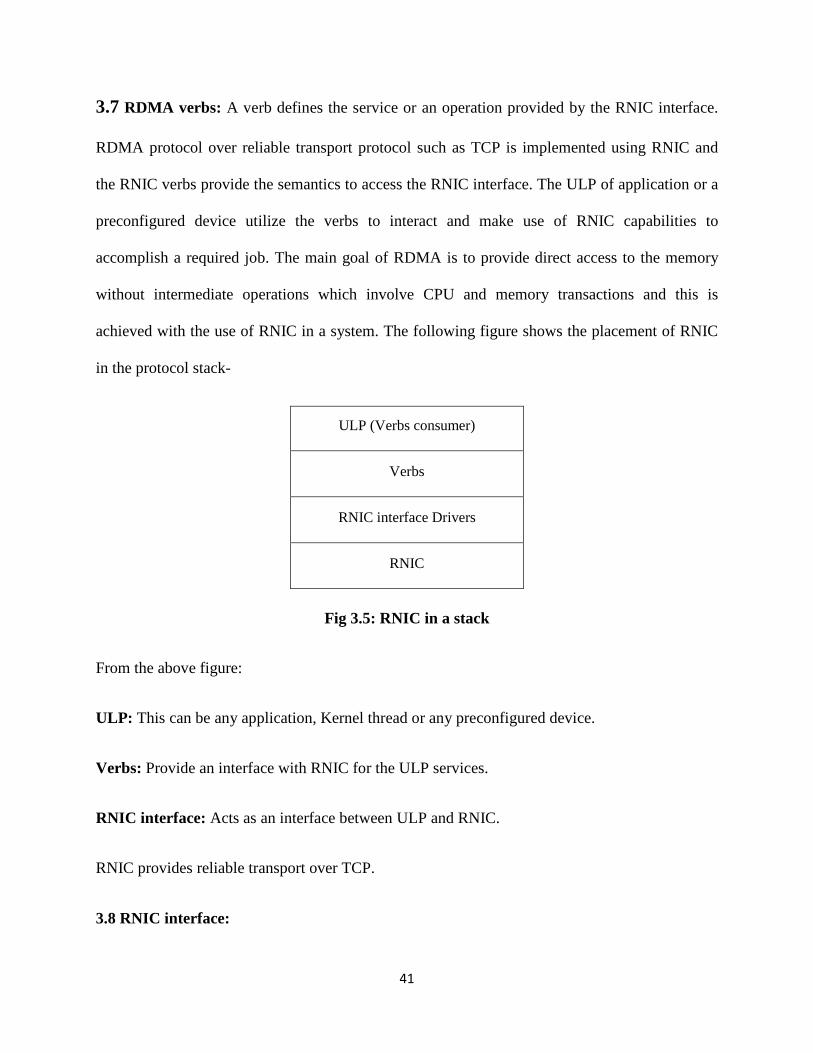
3.7 RDMA verbs: A verb defines the service or an operation provided by the RNIC interface.
RDMA protocol over reliable transport protocol such as TCP is implemented using RNIC and
the RNIC verbs provide the semantics to access the RNIC interface. The ULP of application or a
preconfigured device utilize the verbs to interact and make use of RNIC capabilities to
accomplish a required job. The main goal of RDMA is to provide direct access to the memory
without intermediate operations which involve CPU and memory transactions and this is
achieved with the use of RNIC in a system. The following figure shows the placement of RNIC
in the protocol stack-
Fig 3.5: RNIC in a stack
From the above figure:
ULP: This can be any application, Kernel thread or any preconfigured device.
Verbs: Provide an interface with RNIC for the ULP services.
RNIC interface: Acts as an interface between ULP and RNIC.
RNIC provides reliable transport over TCP.
3.8 RNIC interface:
ULP (Verbs consumer)
Verbs
RNIC interface Drivers
RNIC
42
This acts as an interface between the verb consumer and RNIC. On the RNIC interface
queue pairs are created for the outbound requests, responses and error management. Verbs
specify the function of RNIC, creation, and management of the above specified queue pairs. The
access of RNIC, queue request, other queue components, their management and termination is
provided by the RNIC interface. The queue context is represented as send and receive queue and
this is called as Queue pair. The RDMA write, read and send with all the options are the
operations managed using the send queue. The buffer information and other control messages
received from the remote peer are received and queued to the receive queue. The other queue
present along with these queues is the completion queue (CQ). Upon successfully receiving the
data an into the completion queue, an interrupt is generated by the event handler to the verbs
consumer for the required action to be taken place. The ULP can specify or limit the number of
streams per connection. Apart from the above specified queues Shared Request Queue (SRQ)
[16] can be used to overcome the limit of number of connections. The shared queue is associated
with the other queue pairs and upon receiving any work queue elements they are first received
into the shared queue and are further transferred to their respective queues. Thus the RNIC
serves the purpose of data transfer between two end nodes with the reduced burden over CPU.
43
CHAPTER 4
RDMA ENABLED ROUTER’S ARCHITECTURE AND ITS OPERATIO N
4.1 Introduction
In this chapter, the author first explains the changes made in the routing protocol packet
format [16], router architecture [16] and further explains the operation of the RDMA based
router operation within a router and in between two routers. Author considers the proposed
architecture [16] for all the explanations.
Data packets in a network are carried over IP and this IP traffic is routed using the routing
protocols. Routing protocols route the IP packets from source to destination. The best route to
the destination is based on the routing protocols used in the routers. As discussed in the first
chapter the routing protocol updates the learnt routes to its neighboring routers. These updates
are sent to the neighbors periodically or whenever there is a change in the network. This decision
of updates depends on the type of routing protocol used. In the distance vector routing protocol
the routing updates are sent periodically and in link state the updates are sent whenever there is a
change in the network. The important information sent in these routing updates are the
destination IP address, the interface on the router from which the IP address is learnt and the
destination interface.
4.2 Proposed Changes to routing update packet:
The information sent in the routing updates using the current routing update packet does not
meet the needs of proposed routing architecture. Apart from the information present in the
routing update packet, the information regarding the next hop router’s exit interface, from which
44
the update packet was learnt, is also needed in the routing update. As an example, if x.x.x.x is
received as an update from the neighboring router, the update packet includes the interface from
which the update is learnt and the destination router’s address. So, apart from this information
the exit interface information on the neighboring router from which this route was learnt is
required. To achieve the requirement a new field needs to be added to the existing routing update
packet.
To explain this scenario RIP update packet is considered. RIP is a non proprietary routing
protocol. It is one of the most widely used IGP protocol. The operation of RIP is very simple
compared to other routing protocols. In RIP routing updates are sent periodically. The regular
RIP update packet does not have any information regarding the next hop router’s egress
interface. So in order to achieve the goal of proposed routing architecture [16], egress interface
field details are added in the unused field of the update packet. When a router receives updates, it
changes the metric field before it sends these updates to next hop router. The metric in the case
of RIP is the hop count. Hop count is incremented on each router on the way to the destination.
With the new packet format, apart from the metric field, the egress interface field also needs to
be updated. When a router receives an update packet it updates the routing table with the
destination IP address along with the egress interface detail from the received packet and as the
packet leaves the router, the egress interface field is updated with the interface details from
which the packet came in on that particular router. The original update packet and the proposed
update packets would be as shown.
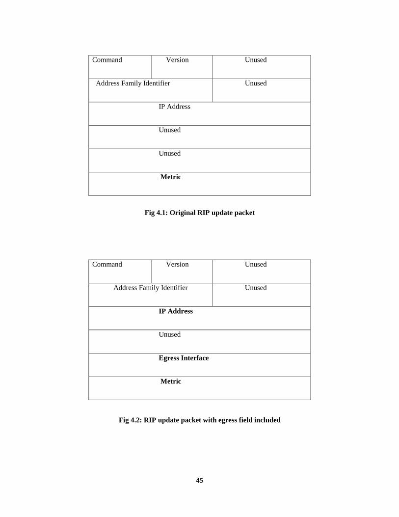
45
Fig 4.1: Original RIP update packet
Fig 4.2: RIP update packet with egress field included
Command Version Unused
Address Family Identifier Unused
IP Address
Unused
Unused
Metric
Command Version Unused
Address Family Identifier Unused
IP Address
Unused
Egress Interface
Metric
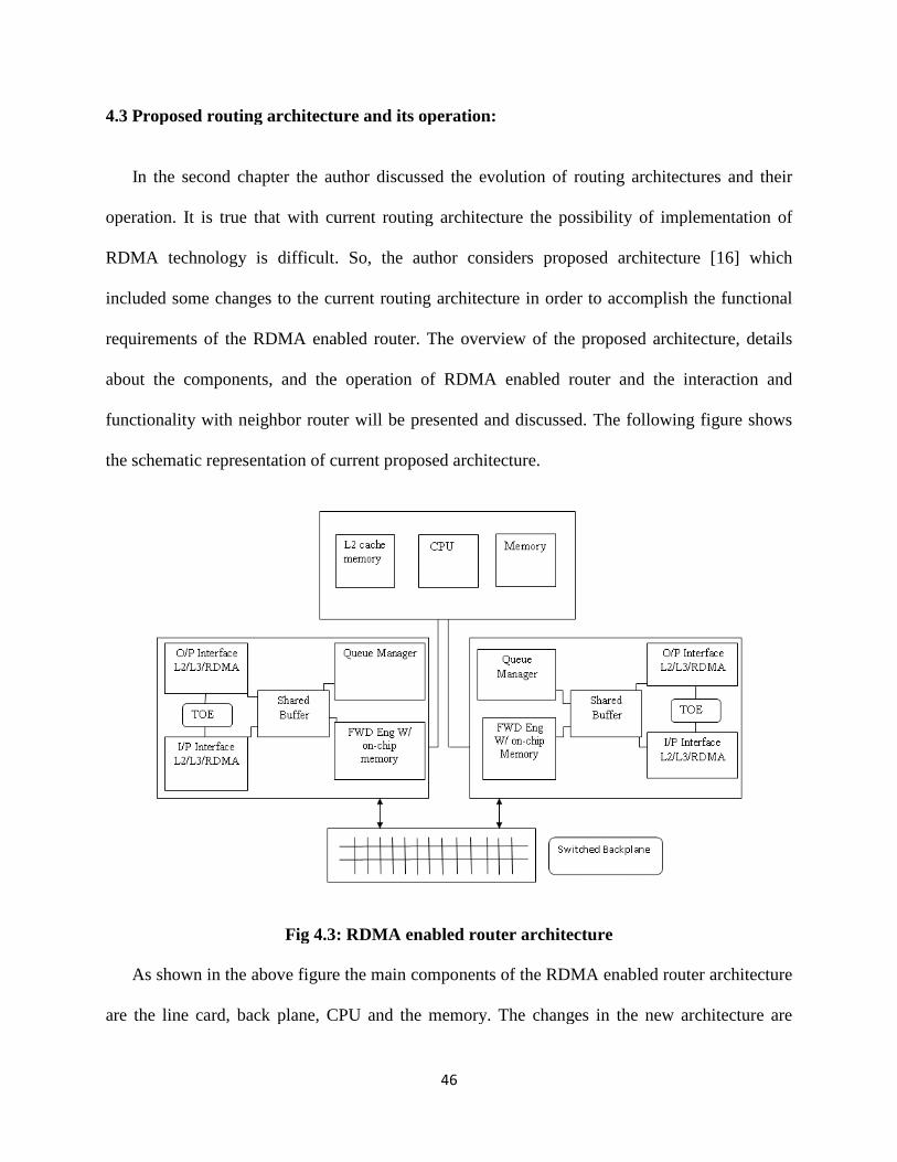
4.3 Proposed routing architecture and its operation:
In the second chapter the author
operation. It is true that with current routing architecture the possibility of implementation of
RDMA technology is difficult. So, the author considers proposed architecture [
included some changes to the current routing architecture in order to accomplish the functional
requirements of the RDMA enabled router. The overview of the proposed architecture, details
about the components, and the
functionality with neighbor router will be presented and discussed. The following figure shows
the schematic representation of current proposed architecture.
Fig 4.3: RDMA enabled router architecture
As shown in the above figure the main co
are the line card, back plane, CPU and the memory. The changes in the new architecture are
46
4.3 Proposed routing architecture and its operation:
In the second chapter the author discussed the evolution of routing architectures and their
operation. It is true that with current routing architecture the possibility of implementation of
RDMA technology is difficult. So, the author considers proposed architecture [
me changes to the current routing architecture in order to accomplish the functional
requirements of the RDMA enabled router. The overview of the proposed architecture, details
and the operation of RDMA enabled router and the interact
functionality with neighbor router will be presented and discussed. The following figure shows
the schematic representation of current proposed architecture.
Fig 4.3: RDMA enabled router architecture
As shown in the above figure the main components of the RDMA enabled router architecture
are the line card, back plane, CPU and the memory. The changes in the new architecture are
discussed the evolution of routing architectures and their
operation. It is true that with current routing architecture the possibility of implementation of
RDMA technology is difficult. So, the author considers proposed architecture [16] which
me changes to the current routing architecture in order to accomplish the functional
requirements of the RDMA enabled router. The overview of the proposed architecture, details
operation of RDMA enabled router and the interaction and
functionality with neighbor router will be presented and discussed. The following figure shows
mponents of the RDMA enabled router architecture
are the line card, back plane, CPU and the memory. The changes in the new architecture are

47
majorly subjected to the line card. All the major implementations of layer 2 and layer 3 are
processed on the line card. If observed from the conventional NIC, the proposed line card
architecture has the capability to process the RDMA, DDP headers along with conventional IP
headers. The major factors that would affect the performance of the routers include TCP/IP
processing, number memory copies made, route lookup time, delay in the input and output
queues.
In conventional router the implementation of TCP/IP is done in software as a part of kernel
and is handled by CPU. This places additional burden on CPU as the TCP connection
establishment which is handled by kernel requires additional CPU cycles. So in the proposed
architecture the TCP connection establishment, data stream initialization and segmentations are
implemented in hardware. In the case of RDMA enabled router the number of TCP connections
made is high than to the conventional router, so the implementation in hardware would relieve
the performance bottleneck with CPU. For this operation the proposed architecture involves the
TCP Offload Engine (TOE) which is discussed later in this chapter. The other advantage of the
RDMA over TCP/IP is that it can handle both block level and file level I/O, thus meeting the
requirements of current day scenario applications. In a conventional router, in order to move the
data from inbound interface to the outbound interface, copies of data are first made on the input
interface, next into memory for processing and finally to outbound interface. This would increase
the time in moving the data packets to the outbound interface, increase the memory requirement
and thereby reducing the performance. In the proposed architecture a copy of data is made on the
inbound interface and outbound interface and fast switching process implemented on the line
card itself moves the data packets from inbound to the outbound without involving the processor,
thereby reducing the delay. The route lookup time and the queuing delay are reduced to a very
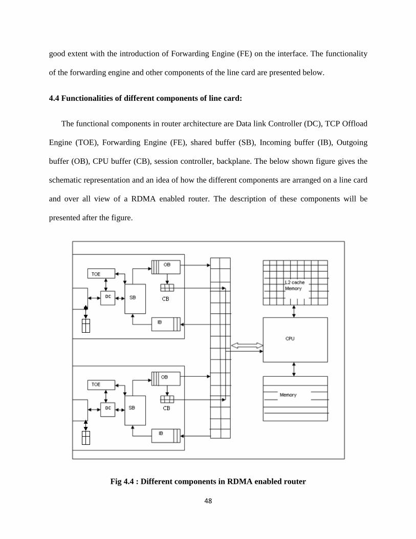
48
good extent with the introduction of Forwarding Engine (FE) on the interface. The functionality
of the forwarding engine and other components of the line card are presented below.
4.4 Functionalities of different components of line card:
The functional components in router architecture are Data link Controller (DC), TCP Offload
Engine (TOE), Forwarding Engine (FE), shared buffer (SB), Incoming buffer (IB), Outgoing
buffer (OB), CPU buffer (CB), session controller, backplane. The below shown figure gives the
schematic representation and an idea of how the different components are arranged on a line card
and over all view of a RDMA enabled router. The description of these components will be
presented after the figure.
Fig 4.4 : Different components in RDMA enabled router
49
TCP Offload Engine (TOE): TCP is the standard protocol used in the networking industry to
move the data. It assures the reliability and provides error free data. With the increase in the
speed of network connectivity, the average numbers of applications run per second have gone
high and the numbers of TCP/IP connections established have increased respectively. This has
kept the processor busy most of the time in processing the TCP/IP stack and has created a
bottleneck in the CPU utilization. So in order to relieve the processor from the processing load a
special hardware called TOE had been introduced, which handles the TCP/IP protocol stack
processing.TOE reduces the processing load of TCP from CPU.
In the proposed architecture, a TCP session is established with every router on the way to the
destination and would have many number of TCP sessions running at a point of time with
different destinations. So the use of TOE relieves the processor and would improve the overall
performance. Processing of TCP traffic is moved to TOE and the control of TOE is left to the
session controller. TCP is a connection oriented protocol and loss of any connection would
involve the processor’s involvement so the presence of TOE would minimize the processor’s
involvement and improves the processor’s utilization for other operations. Since TOE does the
protocol processing it does not consume any CPU cycles and also reduces the number of copies
made before the data is written to the application buffer. TOE also does the checksum
calculations, protocol processing, changing the TCP segment sizes and opens the new TCP
connections. TOE plays main role in high speed networks reducing the CPU overload and the
network latency.
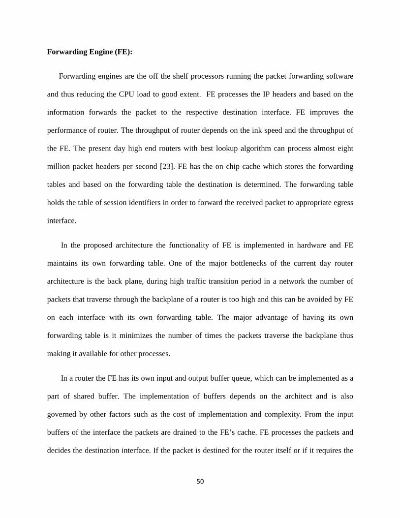
50
Forwarding Engine (FE):
Forwarding engines are the off the shelf processors running the packet forwarding software
and thus reducing the CPU load to good extent. FE processes the IP headers and based on the
information forwards the packet to the respective destination interface. FE improves the
performance of router. The throughput of router depends on the ink speed and the throughput of
the FE. The present day high end routers with best lookup algorithm can process almost eight
million packet headers per second [23]. FE has the on chip cache which stores the forwarding
tables and based on the forwarding table the destination is determined. The forwarding table
holds the table of session identifiers in order to forward the received packet to appropriate egress
interface.
In the proposed architecture the functionality of FE is implemented in hardware and FE
maintains its own forwarding table. One of the major bottlenecks of the current day router
architecture is the back plane, during high traffic transition period in a network the number of
packets that traverse through the backplane of a router is too high and this can be avoided by FE
on each interface with its own forwarding table. The major advantage of having its own
forwarding table is it minimizes the number of times the packets traverse the backplane thus
making it available for other processes.
In a router the FE has its own input and output buffer queue, which can be implemented as a
part of shared buffer. The implementation of buffers depends on the architect and is also
governed by other factors such as the cost of implementation and complexity. From the input
buffers of the interface the packets are drained to the FE’s cache. FE processes the packets and
decides the destination interface. If the packet is destined for the router itself or if it requires the

51
CPU processing the packet is placed in the buffer that is kept aside for CPU access. The packet
destined to other interface is pushed into the FE’s output queue. From the FE’s output queue the
packet is switched through the switching backplane to the destination interface’s FE’s input
queue. From the input queue the packet is handled by the session controller whose functionality
is presented below.
Session Controller: The session controller could be designed in either hardware or software,
depending upon the design requirements. The functions of session controller are as follows.
Session controller periodically checks the FE’s input queue and creates the forwarding table
entry if required. Session controller initiates the TOE for TCP connection based on the
destination address, after the TCP connection establishment by TOE the RDMA mode is
initialized. Stream initialization and handling the tagged buffer information to the DDP layer is
done by the session controller. The details of the destination buffer are entered into the
forwarding table by the session controller before they are handled to the DDP interface.
Shared Buffer: Memory in a router is one of the important components that reflect the
performance of a router. Memory in a router is not restricted to a plane of a router. The data
plane has the interface memory (buffer) and the forwarding plane holds the processor or main
memory. Over the years the cost of memory chips has reduced to a great extent with the
development in CMOS technology. In the proposed architecture the data plane requires memory
or buffer to store the incoming packets, outgoing packets, packets that need to be sent to the
processor, TOE buffers and FE buffers. So the author in the design [16] considered shared buffer
as the data plane memory to minimize the overall cost of the system. This shared buffer is
managed by a kernel process running in the backend of the router. The allotment of required
buffers to the interfaces would depend on upon the request generated by the interface firmware

52
to the kernel. Some of the important circumstances under which the interfaces request for buffers
are- when the packets are queued in the input buffer of the incoming interface for being
processed by the FE, when packets are queued in the buffer that holds the packets to be
processed by the processor. Buffer requirements are also seen when the packets are queued in the
outgoing buffer of the FE or incoming buffer of the interface, this happens when the backplane is
congested with other traffic. In the case of classified packets or the packets that are punted to the
processor such as ping, route updates which require processor action are queued in the buffers
which hold the packets that need to be processed by the processor. In the router before the
packets are sent to the processor they are examined by the traffic manager and are sent to the
respective buffers based on the information in the headers. In general all the specified factors
vary based on the design and architecture.
Backplane: One of the most critical components of a router is the backplane of a router. Several
solutions with different architectures have been proposed to overcome the limitations such as the
congestion in the backplane of a router. Different backplane architectures have been discussed in
the previous chapters. The most common backplane architecture used in the current day router
architectures is the switched backplane architecture.
4.5 Operation of RDMA enabled router:
Till now different components of a RDMA enabled router have been discussed and in the
following sections the operation of a router with RDMA functionality enabled in a router, the
route and data packet exchange process with the neighbor router will be presented.
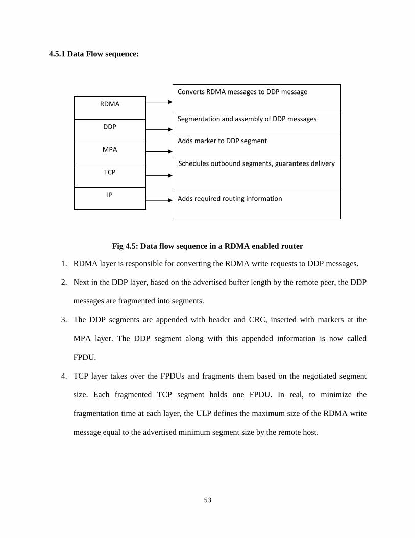
53
4.5.1 Data Flow sequence:
Fig 4.5: Data flow sequence in a RDMA enabled router
1. RDMA layer is responsible for converting the RDMA write requests to DDP messages.
2. Next in the DDP layer, based on the advertised buffer length by the remote peer, the DDP
messages are fragmented into segments.
3. The DDP segments are appended with header and CRC, inserted with markers at the
MPA layer. The DDP segment along with this appended information is now called
FPDU.
4. TCP layer takes over the FPDUs and fragments them based on the negotiated segment
size. Each fragmented TCP segment holds one FPDU. In real, to minimize the
fragmentation time at each layer, the ULP defines the maximum size of the RDMA write
message equal to the advertised minimum segment size by the remote host.
Converts RDMA messages to DDP message
Segmentation and assembly of DDP messages
Adds marker to DDP segment
Schedules outbound segments, guarantees delivery
Adds required routing information
RDMA
DDP
MPA
TCP
IP

54
5. TCP layer delivers the packet to the IP layer where the IP header is appended. The IP
header holds the information regarding the source and destination IP address, identifier,
TTL, protocol details.
6. The IP layer delivers the IP packet to the respective outgoing interface’s DLL controller,
which appends the DLL header based on the ARP table. From here the frame leaves the
router on its way to its destination.
7. When the frame is received at the destination interface the DLL controller first checks the
validity of the frame. If it is a valid frame then it handles the frame to the IP layer after
stripping the DLL header.
8. At the IP layer the packet headers are checked if they are meant to that router, the
identifier field in a packet header determines the position of the packet.
9. If the packets are destined to the router then the packets are handled to the TCP layer
where the packets are reassembled based on the sequence number.
10. The MPA markers that were appended determine the end of the DDP header.
11. From here the DDP segments are written directly into the destination buffer based on the
buffer information present in the DDP header.
The operation in a RDMA enabled router is explained as the operation within a router and the
operation in between two RNIC interfaces of routers.
4.5.2 Operation within a router:
As the data from the physical medium enters the router they are converted into frames and are
handed over to the data link layer protocol controller. It validates the frame, strips off the data
link layer header and places the packet in the input queue of the shared buffer. From here the
packet is sent to the FE cache, which processes the header information and checks the IP field,
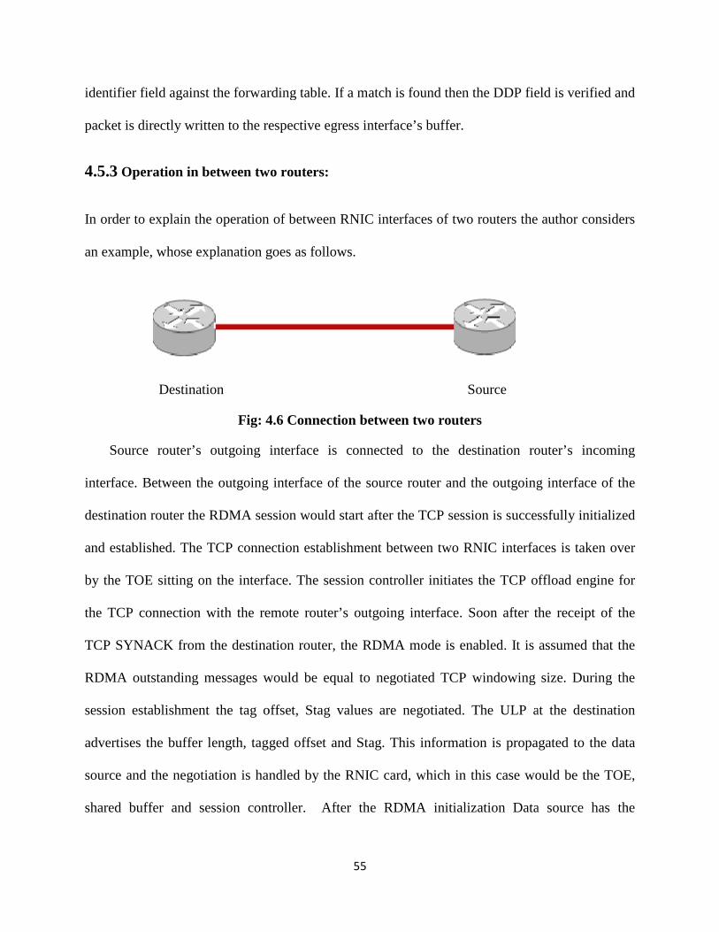
identifier field against the forwarding table. If a match is found then the DDP field is verified and
packet is directly written to the respective eg
4.5.3 Operation in between two routers:
In order to explain the operation of between RNIC interfaces of two routers the author considers
an example, whose explanation goes as follows.
Destination
Fig: 4.6 Connection between two routers
Source router’s outgoing interface is connected to the destination router’s incoming
interface. Between the outgoing interface of the source router and the outgoing interface of the
destination router the RDMA session would start after the TCP session is successfully initialized
and established. The TCP connection establishment between two RNIC interfaces is taken ove
by the TOE sitting on the interface. The session controller initiates the TCP offload engine for
the TCP connection with the remote router’s outgoing interface. Soon after the receipt of the
TCP SYNACK from the destination router, the RDMA mode is enable
RDMA outstanding messages would be equal to negotiated TCP windowing size. During the
session establishment the tag offset, Stag values are negotiated. The ULP at the destination
advertises the buffer length, tagged offset and Sta
source and the negotiation is handled by the RNIC card, which in this case would be the TOE,
shared buffer and session controller. After the RDMA initialization Data source has the
55
identifier field against the forwarding table. If a match is found then the DDP field is verified and
packet is directly written to the respective egress interface’s buffer.
Operation in between two routers:
In order to explain the operation of between RNIC interfaces of two routers the author considers
an example, whose explanation goes as follows.
Source
Fig: 4.6 Connection between two routers
Source router’s outgoing interface is connected to the destination router’s incoming
ng interface of the source router and the outgoing interface of the
destination router the RDMA session would start after the TCP session is successfully initialized
and established. The TCP connection establishment between two RNIC interfaces is taken ove
by the TOE sitting on the interface. The session controller initiates the TCP offload engine for
the TCP connection with the remote router’s outgoing interface. Soon after the receipt of the
TCP SYNACK from the destination router, the RDMA mode is enabled. It is assumed that the
RDMA outstanding messages would be equal to negotiated TCP windowing size. During the
session establishment the tag offset, Stag values are negotiated. The ULP at the destination
advertises the buffer length, tagged offset and Stag. This information is propagated to the data
source and the negotiation is handled by the RNIC card, which in this case would be the TOE,
shared buffer and session controller. After the RDMA initialization Data source has the
identifier field against the forwarding table. If a match is found then the DDP field is verified and
In order to explain the operation of between RNIC interfaces of two routers the author considers
Source router’s outgoing interface is connected to the destination router’s incoming
ng interface of the source router and the outgoing interface of the
destination router the RDMA session would start after the TCP session is successfully initialized
and established. The TCP connection establishment between two RNIC interfaces is taken over
by the TOE sitting on the interface. The session controller initiates the TCP offload engine for
the TCP connection with the remote router’s outgoing interface. Soon after the receipt of the
d. It is assumed that the
RDMA outstanding messages would be equal to negotiated TCP windowing size. During the
session establishment the tag offset, Stag values are negotiated. The ULP at the destination
g. This information is propagated to the data
source and the negotiation is handled by the RNIC card, which in this case would be the TOE,
shared buffer and session controller. After the RDMA initialization Data source has the
56
information regarding the exit interface of the next hop device so that it can queue the packets at
the egress interface directly. Data source writes the data packets into the destination buffers
using RDMA write operation. At the destination the data packets are directly written into the
buffers without the involvement of ULP. The destination buffers remain valid until the ULP of
either the source or the destination invalidates using the invalidate option. Source is the data
source that has the data packets and destination is the data destination to which the data packets
need to be sent. RDMA session Establishment is defined between the source and destination.
The current routers operate based on routing protocols. The packets passing through the
router are routed based on the routes recorded in routing table. The routes and the route updates
of the routing table are sent from the neighboring routers. The neighboring routers send the route
updates whenever there is a change in the route. The current proposed architecture assumes that
the source router’s routing table has the routes with the details of interface from which they are
learnt and also the exit interface from which they are learnt on the neighboring router. This is
accomplished with the inclusion of a new field in the route update packet as explained in the
previous sections.
4.5.3.1 Functionalities of hardware components:
The functionalities of components of RDMA enabled router in the routing and forwarding
process are presented in this section.
Functionalities of TOE:
TCP offload engine is responsible for session establishment between the two RNICS of the
two routers. The two interfaces would be the outgoing interface (source) of first router and the
egress interface (destination) of next hop router.
57
During the session establishment the SYN/SYNACK are sent and certain parameters like MSS,
Window size are negotiated. The window size determines the size of segment that the sender can
send to the destination before the next window size is advertised back. The RNIC buffer holds
the outstanding messages in its send queue. The number of outstanding messages should be
equal to the window size. If that’s not the case then the delay would increase in negotiation and
sending the segments (Delay: If the destination has no enough buffers to accommodate the
incoming data, the source has to wait until the buffers are free and enough buffer size (window)
is advertised or if the advertised buffer size if less, then the source has to divide the segments and
send.). The RDMA messages can be sent as a single message or a number of messages, which
depend on the window size and the MSS negotiated during connection establishment with next
hop egress interface’s RNIC. All these processes should be done by TOE sitting on the line card.
Soon after the TCP connection establishment, the RDMA mode is enabled and the stream
initialization process starts. During this process, the destination advertises the Stag and Tag
Offset.
Stag: This identifies the tagged buffer. This field allows the source to write the data directly into
destination’s buffer.
Tag Offset: This specifies the starting offset, base of the destination’s tagged buffer. This is
where the data is written by the data source. This field allows the destination to place the data
sent by the data source.
Functions of forwarding engine:
On the source router if the packet arrives to the router for the first time then the incoming
packet’s destination address and identifier are checked and compared with the forwarding table.

58
If a match is not found then the route lookup is performed and the information along with the
egress interface is written to outgoing interface’s forwarding engine’s cache. From here the
session controller comes into action.
On the destination router, during the session establishment the forwarding engine makes a
copy of the advertised buffer, identifier and the destination IP address (this copy is made by the
forwarding engine on the destination router on the incoming interface from the source router.
The destination IP address would be destination router’s outgoing interface’s IP address only).
Session identifier would be fixed for each session. During the session establishment the
forwarding engine generates this table and will store it until the session is terminated either by
the source router or the destination router. Now when the packet comes in and if a match is
found then it does not have to check the routing table and forwards it to destination buffer (FE’s
cache). From here the session controller again takes the process of session establishment to next
hop router’s egress interface.
Functions of the session controller:
Session controller checks the input buffer of the forwarding engine. If any entry is found, it
creates corresponding forwarding table. It initiates the TOE for TCP connection and after the
buffer negotiation it handles the packet to the RDMA interface. Presents the Stag and Tag offset
information to the DDP interface.
4.6 Stream Teardown: The RDMA stream could be terminated in the following ways:
ULP graceful termination: This happens when the source initiates the session termination
message. The ULP of the source, after the completion of all the RDMA write messages issues
the session termination message. When this happens the outbound queue of the source’s
59
outgoing interface is empty, which indicates that all the RDMA write requests have been
successfully completed.
LLP abortive termination: Not all the connections in a network are always successful. Some
sessions are terminated because of the errors in the TCP session between the source and the
destination. This type of terminates causes the RDMA session and the source and destination
will not able to exchange any messages until a new session is established.
RDMAP abortive termination: This type of termination is seen when LLP error is reported by
the LLP to the RDMAP layer. This error may or may not result in a loss of data. At times the
data loss may occur when an error is detected by the destination but the destination does not get a
chance to send a terminate message to the source. When an error surfaces at the LLP or the
RDMA layer of the destination, the destination tries to send a terminate message at the earnest
possible, but it might not always be possible for the destination to send the error message before
it terminates the session.
In most of the cases of a session is terminated the messages which were transmitted before the
session termination have to be retransmitted as they are assumed to be completed in error.
60
CHAPTER 5
MATHEMATICAL ANALYSIS, SIMULATION AND RESULTS
In this chapter the author presents the mathematical models for the parameters that are used
to measure the performance of proposed router architecture. The mathematical analysis is also
presented for the legacy router architecture and compared with RDMA based router architecture.
In this chapter mathematical modeling of some of the parameters like delay, processor utilization
and memory utilization in between two routers in the case of RDMA enabled routers is also
presented. Delay includes the delay in a router and delay between two routers and it is analyzed
and presented with appropriate mathematical calculations. Later in this chapter, the CPU
utilization, memory utilization and memory bandwidth utilization are also analyzed and
presented. Apart from the mathematical analysis the router simulator and its functionality is
explained. Finally the simulation results and the respective graphs that show the performance are
presented.
5.1 Performance:
The performance of a network is dependent on various different factors like type of the
links, traffic, intermediate device’s processing speed and also the end devices. One of the
important components in a network that affects the performance of a network is the router. The
performance of a router is based on the processing speed, delay, outgoing link bandwidth and the
memory bus bandwidth in a router. Bandwidth in general determines how much data can be sent
over a medium, processing speed depends on the type of processor. Memory bus bandwidth in a
router depends on the number of packets handled by the processor because most part of the
memory bandwidth is used in moving the incoming and outgoing packets into and out of the
61
memory, in moving the packets to the processor for processing and to the outgoing interface
from memory. All these parameters affect the performance of a router. The overall performance
of a router could be increased by increasing the router’s processor processing capability,
reducing the delay with in a router, making the best use of available memory bus bandwidth
which is a critical resource in a router. The processor’s processing capability can also be
increased by reducing the burden of the processor which is used in packet processing so that the
processor can handle other priority issues.
Delay over the network determines the time taken for a packet to move from the source to
the destination. This includes the link delay, delay in the intermediate devices. The author in this
thesis is concerned about the delay in a router and delay involved in moving a packet from one
interface of a router to the outgoing interface of another router. In a router delay is the time that
the packet takes to move from the input interface of a router to the output interface. From the
moment the packet enters the router it experiences different kinds of delays. These include the
queuing delay which is the delay involved in moving the packets from a the input queue to the
I/O memory, delay in moving the packets to and from the I/O memory to the processor memory,
the delay to move the packets form the I/O memory to the output buffer on the egress interface.
Processing delay is not considered as it is explained as a separate factor in the later sections.
So the total delay involved in the conventional router can expressed as
Total delay = Queuing delay + transmission delay (1)
Here the queuing delay is the time that the packet has to wait in the input and output buffer for
being processed. The transmission delay is the total time that the packet takes to move from the
input interface to the output interface.

62
5.1.1 Transmission delay in a conventional router:
The received bits over the physical interface are handed as the frames to the link layer controller
[1], which validates the frames. The validated frames are converted as packets and sent to the
input buffer or input queue. In conventional routers with no special purpose processors on the
interfaces, when the packet is placed to the input queue an interrupt is generated to the CPU.
CPU fetches the data (header/packet) from the input queue of the input interface and hands over
it to the memory controller, which writes to the I/O buffer, so the delay involved in this process
is considered as T in. From the buffer the memory controller writes the header to the processor
memory where the processing of the header based on the route lookups and other required
configured parameters such as QOS, protocol processing, updates is done by the processor
(Tmem). After the processor processes the header, it is written back to the I/O by the memory
controller (Tmem). The processor now moves the packet form the I/O buffer to the output
interface’s buffer or egress buffer (Tout) depending upon the availability of the egress interface
buffer. So the total transmission delay involved in all these processes is:
TDE = Tin + 2 * Tmem + Tout (2)
5.1.2 Queuing delay:
Queuing delay is not a deterministic value. It depends on many factors within a router such as the
arrival rate Ar (t) of the packets at the input interface, the processor speed (µ), departure rate De
(t) [24]. At the input interface the queuing delay is usually seen when the data packet arrival rate
is higher than the output link capacity which fills in the output queue and the processing speed
which fills in the input queue. The processor processes the packets the in the input queue and
63
send them to the output queue depending upon the availability of free space on the egress
interface. The total time spent by the packet in the queue is calculated as QDE. The author
considers that there are no dropped packets.
The queuing delay can be calculated as:
Ar (t) = P / T (3)
P = number of packets.
T = Time for one session (packets with same identifier)
De (t) = µ (4)
Where µ can be expressed as Pc/Ac
Pc = Processor capacity
Ac = Available capacity
The available capacity is expressed as the percentage of the processor capacity.
µ = Pc / Ac
Length of the queue:
Qt = Ar (t) – De (t) (5)
P/T – (Pc / Ac)
So the total delay can be expressed as
QDE = Qt / µ
QDE = [Ar (t) – De (t)] / µ (6)
So the total delay in the conventional router from (2) and (6) can be written as:
TDC = TDE + QDE

64
TDC = Tin + 2 * Tmem + Tout + [Ar(t) – De(t)]/µ (7)
5.1.3 Delay in RDMA enabled router:
The author compares the delay in a conventional router with delay in RDMA enabled router
architecture. In the RDMA enabled router when the link layer controller places the packet in the
input queue, the packet is drained into the Forwarding Engine’s (FE) output queue on the
incoming interface.
If the operation in between two routers is considered, the corresponding forwarding table (FT) is
already created in the cache of the forwarding engine as explained in the previous chapter. So
based on the FT the packet is sent to the corresponding destination interface FE’s input buffer.
From the FE’s input buffer the session controller handles the packet until it is delivered to the
data link controller. So the transmission delay (Tdr) between the interfaces is quite negligible as
compared to the conventional router since the transmission takes place between the buffers of the
FE on different interfaces through the switching plane. The I/O memory availability, the
processor availability and the respective delay is not involved in any of the processes.
In the RDMA enabled router each interface has shared buffer which holds the input buffer,
output buffer and FE buffers. Compared to the conventional router the queuing delay QDR in the
RDMA enabled router is very less. In a conventional router the packet stays in the queue until
the processor processes the packet by copying it into the I/O buffer. In the case of RDMA
enabled router from the input queue the packet is drained into the FE’s output buffer, from here
the FE processes the packets. FE checks the FT for the exact match of the identifier, destination
address fields and the egress interface. Since the number of entries in the forwarding table would
be quite less as the number of session running would never be equal to the number of routes
recoded, the lookup time would be very less. The forwarding engine maintains two queues for
65
the output and input packets. FE on the incoming interface forwards the packet to the outgoing
interface and the session controller handles the packets as soon as they are placed in the input
queue of the FE input buffer on the outgoing interface. Session controller as discussed in earlier
chapters could be a part of the FE or system kernel whose processing speed and availability
would be high. So, the processing speed is increased twice to the conventional router there by
reducing the delay. Since the transmission delay is also not seen the total delay would be,
QDR = [Ar (t) – De (t)] / 2*µ (8)
TDR = QDR + Tdr (9)
TDR = [Ar (t) – De (t)] / 2*µ (10)
This can be analyzed considering an example as shown.
In a busy network millions of packets are processed per second by the router. Considering an
example, the number of packets that are processed at the input interface of the router are 100000
packets, processing capacity of the processor in a router is ten thousand packets per second.
Time T would be the time taken by the last packet to enter the queue. If the available processing
capacity in a router is 0.1, the delay would be as follows:
Ar (t) = 100000 / 2 = 50000
De (t) = 100 / 10 = 100
From (7) & (10)-
TDC = [50000 – 10] / 10000 = 4.99 secs.
TDR = [50000 – 10] / 20000 = 2.49 secs.
The processing speed of the processor and the number of packets that arrive are usually in
millions and the processing delay would reduce to milliseconds per session. The author considers
these values for easy evaluation. This delay does not consider the transmission delay that was

66
presented for the conventional router. Thus the total delay in a conventional router calculated per
session is higher that the RDMA enabled router.
5.2 Processing and transmission delay between routers:
The author considered the proposed architecture [16] to show the operation and the simulation of
the packet processing in the RDMA enabled router. With the RDMA enabled router, a session is
established with the next hop router’s egress interface as explained in the previous chapter. So
the author in this section presents the comparative study of the delay involved in moving a
packet from the egress interface of the source router to the egress interface of the destination
router in both the conventional router and the RDMA enabled router. Author also presents the
simulation results of the respective studies. For better and good analysis the author considers the
study and simulation between two routers only and this can be applied over the network with
multiple routers.
The transmission delay is the delay experienced by a packet from the source router’s egress
interface to the destination router’s egress interface. The process starts with the TCP connection
establishment by the source router egress interface’s TCP Offload Engine with the destination
router (next hop router) egress interface.
Over the network any reliable communication between any two devices starts with the TCP
session establishment. The delay in TCP connection establishment is nothing but the TCP
session negotiation delay. The delay Tcp is the time difference between the time stamps from the
moment the first SYN packet is sent to the moment the first data packet is sent. So in the
conventional router the delay Tcp would be,
Tcp = Tdata – Tsyn (11)
67
In conventional routers the TCP connection establishment includes the involvement of the
processor and certain percent of the processor’s capability is used. Where as in the case of the
RDMA enabled router the TCP offload engine takes care of the TCP connection establishment
with the remote router, thus reducing the load on the router’s processor and also the delay Tx to
some extent. After the TCP session is established the RDMA mode is enabled between these
interfaces. So the delay Tcpr in RDMA enabled router would be
Tcpr = (Tdata – T syn) – Tx + Tr (12)
Tx is the reduced delay in the case of RDMA enabled router.
Tr is the time required for RDMA mode to begin.
5.2.1 Processing delay in packet processing:
The author considers the delay calculation in the proposed architecture [16] as a base for the
following calculation. Delay in the packet processing is one of the main reasons for the
development of the new routing architectures. In a conventional router when a packet needs to be
sent to the destination, the route lookup is done for every packet. Apart from the route lookup
some amount of time is spent on the IP header processing (I ph) on the egress interface, this is
common in RDMA enabled router and the conventional router. At the next hop router again
based on the destination address the route lookup needs to be done against the routing table. The
route lookup delay (I pr) includes the route lookup time from the routing table Rl and the
processing delay I pp. The route lookup time Rl is directly proportional to the size of the routing
table Rs, presence of the FIB or fast cache
Fc and the hardware FE that is responsible for these route lookups on the interface.
68
Therefore, Rl α Rs
α (1 / Fc * FE )
I pr = Ipp + Rl (13)
This would be true for each and every packet in the conventional router architecture. With the
increase of the routing table the route lookup time gradually increases. The route lookup time
also depends on the location of the route in the route table. With the presence of the special
hardware like the forwarding engine and the cache or FIB on the interface the route lookup time
decreases.
Apart from these factors the processing of the packets in the router also depends on the type
of traffic. Classification of the packets based on the applications such as multimedia or any data
application is done by configuring QOS parameters in the outgoing packets by the host which
initiates the traffic. Based on the classification parameters the routers process the packets
differently. The delay involved in processing these special packets is Tq. So the total time that
the packet takes to move from one interface to the other interface of the router is
Tcr = Tcp + Iph + Ipr + Tq (14)
In the case of the RDMA enabled router, during the session establishment between the source
router’s egress interface and the destination router’s egress interface the route lookup is done
from the FIB stored in the shared buffer of the interface. After the TCP session establishment
some time is taken to start the RDMA session so the delay TCP in this case would be TCPR. The
header processing includes the IP header processing I ph and also the RDMA header processing
Rh. The route lookup from the FIB is done for the first packet and the details regarding the
destination interface and the egress interface of the next hop details are stored in the forwarding
table generated by the session controller.
69
From the second packet until the end of the session the lookup is done form the forwarding table.
Even on the next hop router’s ingress interface the forwarding table is used for the route look up
to send the packet to the respective egress interface. So the time taken to do a lookup in the
forwarding table would be Ftl.
So if there are N packets for a session, then
I pr = Rl + Ipp + Rh + Tq + N-1 ( 2Ftl + Ipp + Rh + Tq) (15)
So the total delay involved in RDMA enabled router from (12), (13), (14) and (15) can be shown as
Trr = Tcpr + Iph + Ipr + Tq + Rh (16)
If considered for N packets,
Trr = Tcpr + Iph + Rh + Rl + N-1(2F tl + Ipp + Rh + Tq) (17)
Tcr = N ( Tcp + Iph + Ipp + Rl + Tq) (18)
Apart from the above results the author also simulates the memory utilization and the CPU
utilization based of both the conventional router and the RDMA enabled router which is
presented in the proposed router architecture [16].
5.3 Memory utilization in a conventional router:
Memory utilization in the proposed architecture is presented as the memory utilized for the
TCP connection, CPU buffers, and interface buffers. For every session a TCP session is
established with the destination interface’s egress interface. Buffers used on the ingress interface
during TCP connection establishment on the are shown as,
MBN = MSe1 + MSe2 + ….. + MSen

70
��� � ∑��� ���
MTIB = MBN1 + MBN2 + ….. MBNp
���� � ∑���� ��� (19)
MSe - The minimum buffer that is required for the every session or stream terminating on the
input interface. It is assumed that TCP stream terminates on an ingress interface and some
amount of buffer need to be allocated for the input interface.
MBN - The total buffer required for N streams terminating on the input interface.
MTIB – Total buffer required on a router if a router has P interfaces and N streams.
Similarly on the outgoing interface the buffer required would be
MBON = MSTO1 + MSTO2 + ….. + MSTOn
���� � ∑��� ���� (20)
MTOB = MBON1 + MBON2 + ….. + MBONp
���� � ∑���� ��� (21)
���� � ∑���� ���� (22)
MSTO - The minimum buffer that is required for the every session or stream terminating on the
output interface.
MBON – Total memory required for N sessions terminating on each egress interface.
MTOB – Total buffer required on a router if a router has P interfaces and N streams.
71
In a router after the TCP connection establishment the packets arrive at the input interface. In a
conventional router before the packet is moved to the outgoing interface, different copies of the
packet are made within the router. In some routers a copy of the packet is made on the incoming
interface’s cache, which is used as a lookup table the next incoming packets. If the packet needs
to be processed by the processor, the packet has first to be copied to the memory buffer by the
processor. This buffer is the I/O memory buffer. From the I/O buffer a copy is made again to the
CPU buffer for the processor to process the packet, after the processor processes the packet it is
again moved to the I/O buffer. From the I/O buffer the packet is sent to the outgoing interface
buffer by the processor. So the memory utilized in all these processes per interface is presented
as,
MECPU = ((S+20) * NP)) + ((S+20) * NP)) + …… + ((S+20) * NP))
������� � ∑ ��� ��� � ��� � ���
MECPU - Memory required on an interface with NP number of packets per stream terminating on
an interface.
MET CPUI – Total memory required on an interface with N streams, each with NP packets
terminating on a interface.
MTCPU – CPU memory required if N active streams are terminating on the ingress interface.
S – Average packet size in a stream.
NP – Number of packets in a stream.
If a router has P interfaces then the total CPU memory M��� required in a router would be,
72
MTCPU = METCPU1 + METCPU2 + ….. METCPUi
����� � ∑ ��� ������ (23)
So, the total memory utilization in a conventional router required for destination lookup, packet
processing and buffering of the packets is presented as
��! � ����� � ���� � ���� (24)
5.3.1 Memory utilization in RDMA enabled router:
In the case of RDMA enabled router, the route lookup mechanism is done by the forwarding
engine. For each session, forwarding table is created and stored on the on-chip cache of the
forwarding engine. This forwarding engine stores the destination buffer information such as
Stag, Tagged Offset, destination IP address and corresponding egress interface. In the case of
RDMA enabled router, the memory required is only the buffer for storing the packets on the
input interface while the lookup is done and on the egress interface during the RDMA header
processing is done. So the total memory required in the case of RDMA router would be sum of
the interface buffer and FE buffer. Both the incoming and outgoing interface buffers would be
same as the conventional router but the FE buffer would be almost half the size as the processing
speed is doubled in the case of RDMA enabled router. So the total memory required in this case
would be,
� !! � � ��� �� ��� + (MTCPU /2) (25)
� ��� - Summation of total buffer required on the input interface.
M TOB – Summation of total buffer required on the egress interface.
73
So the total memory required in the case of RDMA enabled router, in transmitting the packets of
a session from the input interface to the output interface is minimum compared to the
conventional router. The author also showed that the copy mechanism involved between the
CPU and I/O memory is minimized thus saving the CPU utilization and memory.
5.4 CPU utilization:
In a conventional router, the process of route lookup, moving the packet from the input interface
to the I/O memory and moving back the packet header to the output interface is done by the
processor. The total number of CPU cycles involved in all these processes has been presented.
When the packet arrives on the ingress interface packet has to be analyzed and a packet context
has to be created by the processor. This packet context has the destination ip address which is
used to get the information of the outgoing interface. So for the creation of the packet context,
the packet has to be copied to the I/O memory and processed. Creation of the CPU context
requires one CPU cycle TCPUC. After the creation of the packet context, the processor now needs
to lookup the destination interface using the routing table. Route lookup is done against the
routing table until the exact match for the destination interface IP address is found. The number
of CPU cycles TLOOK required depends upon the size of the routing table. As the size of the
routing table increases the CPU cycles required for route lookup increase. After the route lookup
is done, the packet needs to be copied to the egress interface buffer. The number of CPU cycles
required to move the packet context from the input interface to the I/O buffer is equal to the
number of cycles required to move to the packet context from the I/O buffer to the output
interface. Considering that the processor can copy X bits per copy cycle, NP packets can be
74
copied in (NP*8) / C cycles. Total number of CPU cycles required for transferring the packets
from input buffer to the output buffer is presented as,
���" � � � ��� � #� / �
Finally total number of CPU cycles required for a packet to move from input interface to the
output interface is presented as
%&�'( � %&�'& � %)**+ � %&�, (26)
5.4.1 CPU utilization in case of a RDMA enabled router
In the case of RDMA enabled router, the packet context includes the RDMA header along with
the IP header. So two CPU cycles are required in creating the packet context. After the creation
of the CPU context, it is copied back to the forwarding engine’s on-chip cache where the
forwarding table is stored. The forwarding table is populated by the session controller which can
be a part of the CPU or the RNIC itself. In this case, considering the session controller to be a
part of CPU, then the number of CPU cycles TFT utilized in creation of the FT depends on the
number of advertised buffers by the egress interface. So the total CPU utilization in the case of
RDMA enabled router is the summation of the TFT and Tpc -
� !! � � -� � � ����! (27)
5.5 Router Simulator:
5.5.1 Simulator explanation:
In order to simulate the proposed architecture operation, author has designed a router simulator
which emulates the router operation. Two different router simulators have been designed, one

75
emulates the legacy router operation and second simulator includes two routers which show the
operation of RDMA based router architecture. Similar to the real time router the designed router
has the interfaces, buffer on the interfaces, main memory and forwarding engine and session
controller operations. The simulators have the capability to show the route table lookup
procedure, decision making of the outgoing interface based on best route in the route table and
generation of forwarding table on the interfaces. For both the router simulations RIP protocol has
been considered as the routing protocol for route table generation and in decision making. The
presence and purpose of the new field included in RIP update packet has been shown in the
simulation process. The design of the router simulators is completely modular and extensible
which allows future users to add additional functionalities if required. In order to show that the
operation of the simulated router is close to the real time router operation and also to show that
the operation of RDMA router is possible, the author implemented the functionalities of all the
components as in original router.
5.5.2 Description of simulator:
The main function of the router is to route the packets to appropriate destination interfaces based
on the destination IP address and the route table. Apart from this, router updates the routes
received in route updates, updates the TTL field, updates the interface buffer which holds the
routing tables for fast processing and updates the source with destination unreachable if any
packet has no route in the route table. All these functionalities have been implemented in the
designed router simulator. In the case of RDMA enabled router, two routers are considered and
the RDMA based operation between these two routers is shown clearly. When a packet comes in
on the input interface, the destination IP address is checked and based on the route table on the
interface cache the destination interface is decided. In the case of no route in the interface’s route
76
cache the packet is forwarded to the processor and the main route table is checked. If route is
found then the packet is forwarded to the respective outgoing interface and the interface route
cache is updated with this route entry. In case of no route, the source is updated with destination
unreachable message. In the case of RDMA function enabled router when a packet comes in,
forwarding table is first checked and based on the entry the outgoing interface is decided. As the
packet reaches the outgoing interface a session is established with the next hop routers outgoing
interface and the packet is directly written into the buffer of that interface. If a packet is destined
to the router, then the incoming interface moves the packet to the processor buffer for further
processing. In this process the route table, forwarding table, interface route cache entries are
created. All these can be viewed using the simulator options. The provision of adding an
interface, deleting an interface, changing the IP address of an interface and debugging the
process of router operation have also been designed.
5.5.3 Simulator Environment:
Router Simulation Software Code: C
Code simulator: Turbo c++
OS: Windows XP professional
5.5.4 Snapshots of Simulator:
Only the running configuration output of a router is shown in the below snapshot . All other outputs are clearly explained in appendix A.
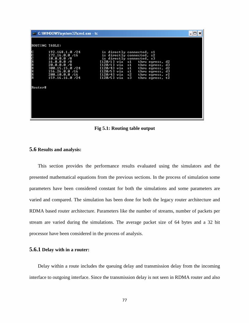
77
Fig 5.1: Routing table output
5.6 Results and analysis:
This section provides the performance results evaluated using the simulators and the
presented mathematical equations from the previous sections. In the process of simulation some
parameters have been considered constant for both the simulations and some parameters are
varied and compared. The simulation has been done for both the legacy router architecture and
RDMA based router architecture. Parameters like the number of streams, number of packets per
stream are varied during the simulations. The average packet size of 64 bytes and a 32 bit
processor have been considered in the process of analysis.
5.6.1 Delay with in a router:
Delay within a route includes the queuing delay and transmission delay from the incoming
interface to outgoing interface. Since the transmission delay is not seen in RDMA router and also
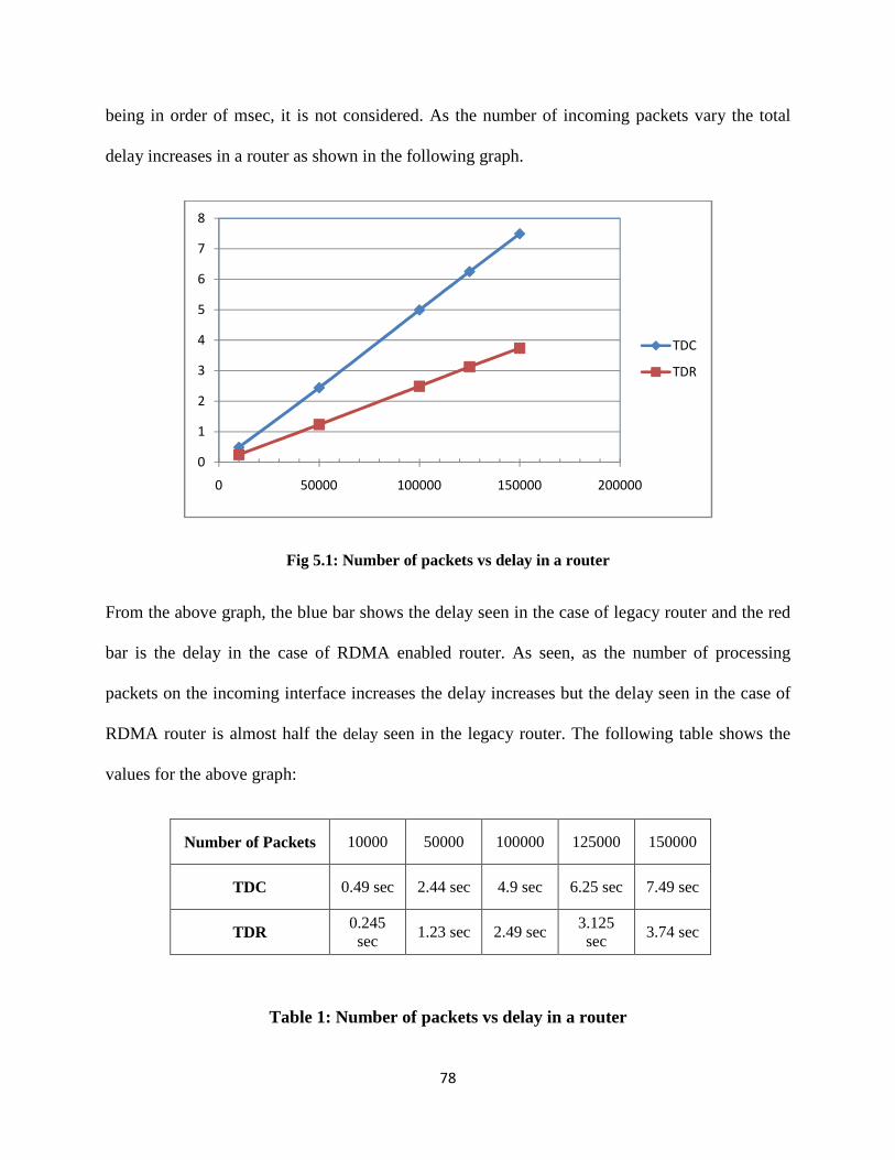
78
being in order of msec, it is not considered. As the number of incoming packets vary the total
delay increases in a router as shown in the following graph.
Fig 5.1: Number of packets vs delay in a router
From the above graph, the blue bar shows the delay seen in the case of legacy router and the red
bar is the delay in the case of RDMA enabled router. As seen, as the number of processing
packets on the incoming interface increases the delay increases but the delay seen in the case of
RDMA router is almost half the delay seen in the legacy router. The following table shows the
values for the above graph:
Number of Packets 10000 50000 100000 125000 150000
TDC 0.49 sec 2.44 sec 4.9 sec 6.25 sec 7.49 sec
TDR 0.245 sec
1.23 sec 2.49 sec 3.125 sec
3.74 sec
Table 1: Number of packets vs delay in a router
0
1
2
3
4
5
6
7
8
0 50000 100000 150000 200000
TDC
TDR

79
5.6.2 Delay in between two routers:
Delay in between two routers includes several factors such as TCP session establishment delay,
IP header processing delay, route lookup delay. Some of the parameters are considered constant
as explained before and the number of packets and the sessions per interface are varied. The
below given table shows the constant considered values.
TCP = 5 ms Iph = 2 ms I PP = 2 ms Rh = 1 ms
Rl = 3 ms Tq = 2 ms Ftl = 1 ms Tcpr = 7 ms
Table 2: Table that shows the constant values
The above values are considered and the numbers of packets per session are varied and the delay
was analyzed. As shown in the below graph, in the case of conventional router for all the packets
the delay would be constant since every packet would be processed in the same manner but in
the case of RDMA enabled router the first packet takes the route lookup procedure and the next
packets would be checked with the forwarding table, which take less time. This analysis has been
explained considering that there are no drops in packets.
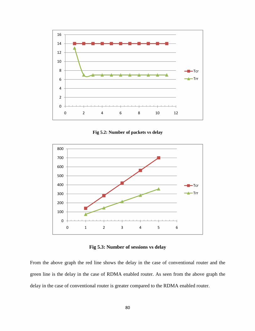
80
Fig 5.2: Number of packets vs delay
Fig 5.3: Number of sessions vs delay
From the above graph the red line shows the delay in the case of conventional router and the
green line is the delay in the case of RDMA enabled router. As seen from the above graph the
delay in the case of conventional router is greater compared to the RDMA enabled router.
0
2
4
6
8
10
12
14
16
0 2 4 6 8 10 12
Tcr
Trr
0
100
200
300
400
500
600
700
800
0 1 2 3 4 5 6
Tcr
Trr
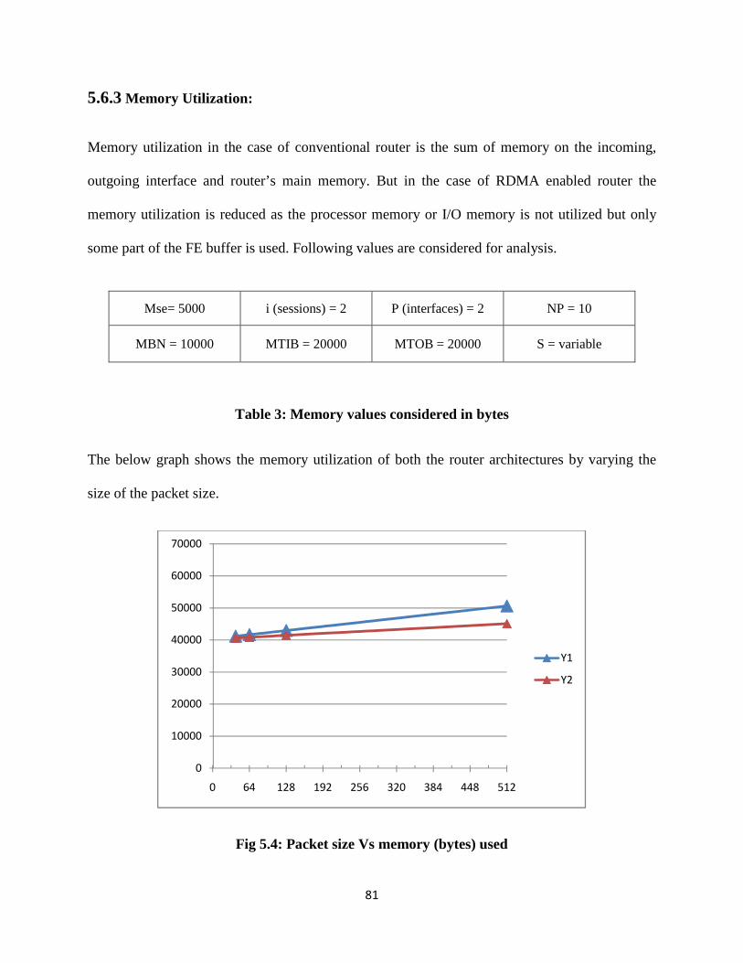
81
5.6.3 Memory Utilization:
Memory utilization in the case of conventional router is the sum of memory on the incoming,
outgoing interface and router’s main memory. But in the case of RDMA enabled router the
memory utilization is reduced as the processor memory or I/O memory is not utilized but only
some part of the FE buffer is used. Following values are considered for analysis.
Table 3: Memory values considered in bytes
The below graph shows the memory utilization of both the router architectures by varying the
size of the packet size.
Fig 5.4: Packet size Vs memory (bytes) used
0
10000
20000
30000
40000
50000
60000
70000
0 64 128 192 256 320 384 448 512
Y1
Y2
Mse= 5000 i (sessions) = 2 P (interfaces) = 2 NP = 10
MBN = 10000 MTIB = 20000 MTOB = 20000 S = variable

82
The above graph shows that the memory utilization in the case of RDMA enabled router is
minimized to the conventional router as explained previously.
5.6.4 CPU utilization:
As shown in the above sections the CPU utilization is measured as the number of CPU cycles
spent in the header processing, route lookup and CPU cycles spent in moving the IP packets
from the input interface to the CPU memory and back from the CPU memory to the output
buffer. Varying the packet size the number of CPU cycles required is analyzed. Assuming the
CPU cycles required for the route lookup, header processing, CPU cycles required for FT lookup
is constant the below given values are considered.
TCPUC = 1 TCPUCR = 2
TLOOK = 3 TFT = 3
Table 4: CPU cycles for different operations
The below graph shows the CPU utilization in terms of number of CPU cycles required as the
size of the packet is varied. The 32 bit processor is considered for the analysis.
Fig 5.5: CPU utilization Vs packet size (32 bit)
0
100
200
300
400
500
600
32 64 128 512 1024
Tcpur
Trr
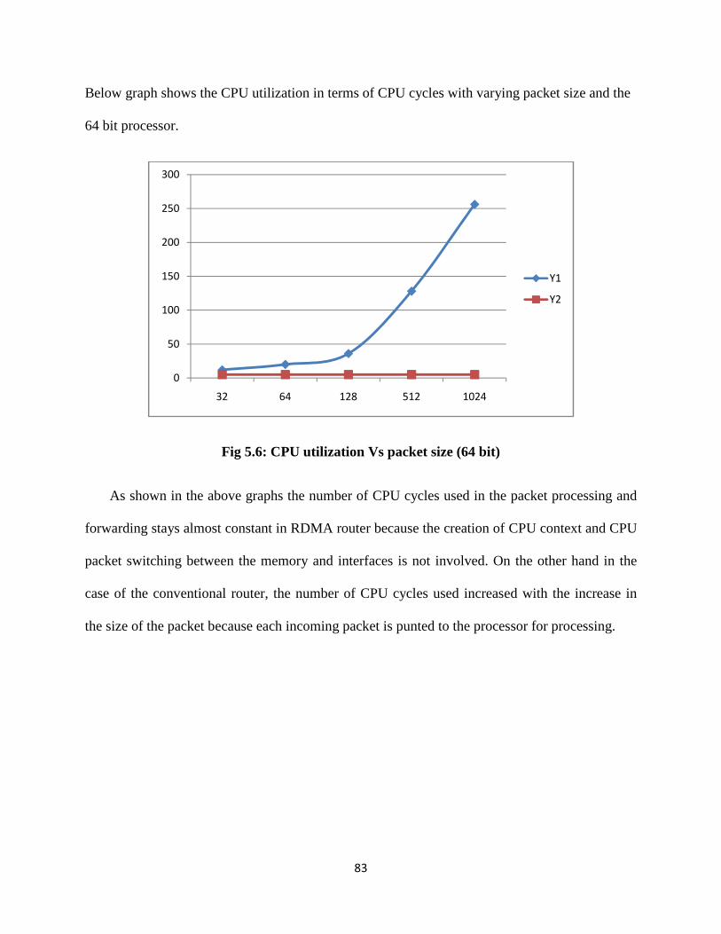
83
Below graph shows the CPU utilization in terms of CPU cycles with varying packet size and the
64 bit processor.
Fig 5.6: CPU utilization Vs packet size (64 bit)
As shown in the above graphs the number of CPU cycles used in the packet processing and
forwarding stays almost constant in RDMA router because the creation of CPU context and CPU
packet switching between the memory and interfaces is not involved. On the other hand in the
case of the conventional router, the number of CPU cycles used increased with the increase in
the size of the packet because each incoming packet is punted to the processor for processing.
0
50
100
150
200
250
300
32 64 128 512 1024
Y1
Y2
84
CHAPTER 6
CONCLUSIONS AND RESULTS
6.1 Conclusions:
In this thesis work, the author presents the operation, analysis and simulation of RDMA
based router architecture. Parameters like total delay, processing delay, memory and processor
utilization have been modeled, analyzed and compared. The proposed architecture makes use of
the forwarding table for route decisions and also updates the forwarding tables. As seen from the
latency and performance analysis the proposed architecture based router operation provides good
improvement over the legacy architectures, especially in the case of high traffic load. The results
also show that the proposed router architecture based operation alleviates the CPU burden,
reduces the memory utilization and also reduces the number of times the packet traverses
through the backplane of the router. Addition to this the number of packet copies that are made
in a router before the packet is sent out is also reduced, thus making the overall memory
requirement less compared to the legacy router architecture. Added to the operational and
functional analysis, a router simulator has been presented which does most of the functions of a
real time router. The simulator is modular, scalable and extensible such that the new users can
understand the internal operation of a router to a good extent and can use it for their research
works.
6.1 Future work:
In current network scenarios QOS implementation is given a higher priority. Modeling the
architecture with QOS implementation techniques in a RDMA based router can be a good area of
85
research. Buffer arrangement, buffer management and buffer advertisement procedures require
more attention and are a vast area of research. Real time implementation of buffer organizer,
session controller and Forwarding engine in hardware can improve the throughput to a great
extent and is highly desirable. The capability of RDMA protocol to handle UDP traffic and its
implementation mechanisms is an open area for research.

86
REFERENCES
87
REFERENCES
[1] A Remote Direct Memory Access Protocol Specification, RFC 5040 http://www.ietf.org/rfc/rfc5040.txt [2] Hemal Shah, Intel Corporation, James Pinkerton, Microsoft Corporation, Renato Recio, paul Culley, Hewlett-Packar., “DDP Protocol Specification, Direct Data Placement Over Reliable Transports”, Release Specification of RMDA Consortium, October 2002. http://www.rdmaconsortium.org/home/draft-shah-iwarp-ddp-v1.0.pdf [3] Introduction to RDMA http://en.wikipedia.org/wiki/Remote_Direct_Memory_Access
[4] Tanenbaum, Andrew S., Computer Networks, 3rd Edition, Eastern Economy Edition, 2005. [5] David A. Patterson and John L. Hennessy., Computer Organization and Design, The Hardware/Software interface, Elsevier, 2005.
[6] Larry L. Peterson and Bruce S. Davie., Computer Networks, A systems Approach, Fourth Edition, Morgan Kaufman Publishers, 2007.
[7] RDMA Over IP Statement, RFC 4297 http://www.ietf.org/mail-archive/web/ietf-announce/current/msg01849.html [8]. The Architecture of Direct Data Placement and Remote Direct Memory Access on Internet Protocols, RFC 4296 http://www.ietf.org/mail-archive/web/ietf-announce/current/msg01848.html [9] James Aweya., “IP Router Architectures: An Overview”, A Draft, Nortel Networks, Ottawa, Canada, K1Y 4H7 [10] Kiran Mukesh Misra and Freddy Kharoliwalla., “Study of Internet Router Architectures”, Technical report, Michigan State University, May, 2001. [11] Andras Csaszar, Traffic lab, Erricson Research, Gabor Yendi and Gabor Retvari, Budapest University of Technology and Economics, Markus Hidell and Peter Sjodin, the Royal institute of Technology., “Converging the Evolution of Router Architectures and IP Networks”, IEEE Network Journal, volume 21, issue 4, July-August 2007. [12] Muzammil Iqbal., “Advanced Core Router Architectures- A hardware Perspective”, Department of Electrical and Computer Engineering, University of Delaware, DE 19716 www.eecis.udel.edu/~iqbal/arch_final_change.pdf [cited 20 August 2008].
88
[13] “Router Architectures- An Overview of router architectures” http://www.cs.virginia.edu/~cs458/slides/module09b-routers.pdf [cited 20August 2008]. [14] Gorry Fairhurst, “Router Operation: An overview”, EG3557, [online document] January 200, http://www.erg.abdn.ac.uk/users/gorry/course/inet-pages/router-opn.html [cited 10 August 2008] [15] Amarnath Pallampati., “ iSCSI Performance Over RDMA-Enabled Network”, Thesis(M.S), Wichita State University, College of Engineering, July 2006. [16] Nishanth Chintalapani., “RDMA based Routing Protocols and Routing Architecture”, Thesis(M.S), Wichita State university, College of Engineering, June 2008.
[17] Feng Gao, Fend Wang, Jie Yang, University of Michigan, Ann Arbor., An IP Forwarding Engine Design For Terabit Routers. [18] RDMA Protocol: Improving Network Performance, Technology Brief, White paper, HP, Nov 2006. http://h20000.www2.hp.com/bc/docs/support/SupportManual/c00589475/c0058 9475.pdf [19] Dennis Dalessandro, Ohio Supercomputer Center, Ohio., “RDMA Over TCP/IP: The Next Step In Ethernet Technology” in proceedings of IEEE Cluster 2006, RAIT Workshop, Barcelona, Spain, Sep 2006. [20] Renato Recio., “RDMA Enabled NIC (RNIC) Verbs Overview”, RDMA consortium, April 2003, pp. 1-10. [21] Cisco 3600 Router Architecture, Cisco 3600 Series Multiservice Platforms Document, Cisco Systems www.cisco.com/en/US/products/hw/routers/ps274/products_tech_note09186a 00801e1155.shtml [22] Michael Beesley, Engineering Director, Router Technology Group, “Router Software Architecture- Now and Going Forward”, Cisco Systems, pp 10-18, 2006. [23] L. Bhuyan and H. Wang., “Execution Driven Simulation of IP Router Architectures”, IEEE International Symposium on network Computing and Associations (NCA01), pp.1045, 2001. [24] Abhay Parekh, “Router Design: Table Lookups and Packet Scheduling”, EECS: Lec 13, Department of Electrical and computer Engineering, University of California, March 2003. http://robotics.eecs.berkeley.edu/~wlr/lookupsched.pdf [25] Wajdi Louati, Badii Jouaber and Djamal Zeghlache., Configurable Software-based
89
Edge Router Architecture, 4th Workshop On Applications and Services in Wireless Networks, Boston, USA. [26] Direct Memory Access http://en.wikipedia.org/wiki/Direct_memory_access

90
APPENDICES
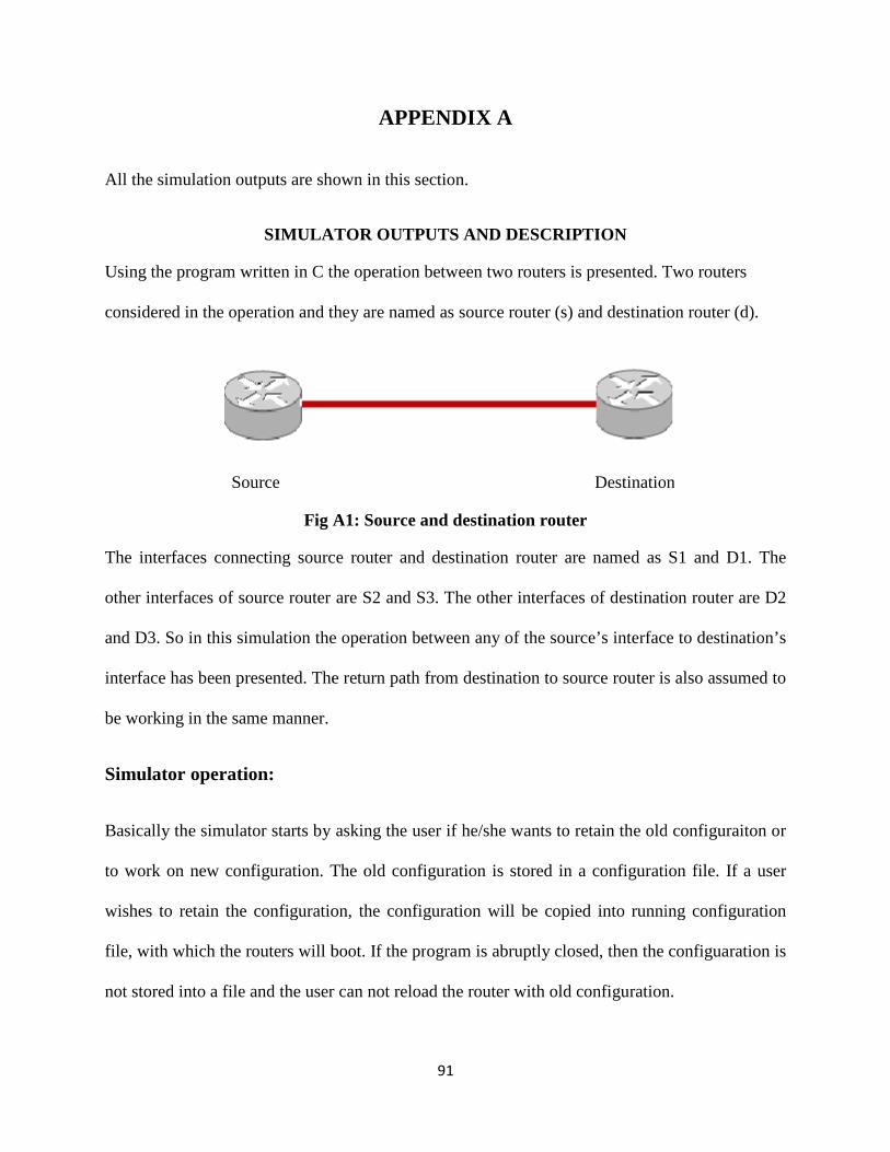
All the simulation outputs are shown in this section.
SIMULATOR
Using the program written in C the operation between two routers is presented. Two routers
considered in the operation and they are named as source router (s) and destination router (d).
Source
Fig A
The interfaces connecting source router and destination router are named as S1 and D1. The
other interfaces of source router are S2 and S3. The other interfaces of destination router are D2
and D3. So in this simulation the operation between any of the source’s interface
interface has been presented. The return path from destination to source router is also assumed to
be working in the same manner.
Simulator operation:
Basically the simulator starts by asking the user if he/she wants to retain the old con
to work on new configuration. The old configuration is stored in a configuration file. If a user
wishes to retain the configuration, the configuration will be copied into running configuration
file, with which the routers will boot. If the pr
not stored into a file and the user can not reload the router with old configuration.
91
APPENDIX A
All the simulation outputs are shown in this section.
SIMULATOR OUTPUTS AND DESCRIPTION
Using the program written in C the operation between two routers is presented. Two routers
operation and they are named as source router (s) and destination router (d).
Destination
A1: Source and destination router
connecting source router and destination router are named as S1 and D1. The
other interfaces of source router are S2 and S3. The other interfaces of destination router are D2
and D3. So in this simulation the operation between any of the source’s interface
interface has been presented. The return path from destination to source router is also assumed to
Basically the simulator starts by asking the user if he/she wants to retain the old con
to work on new configuration. The old configuration is stored in a configuration file. If a user
wishes to retain the configuration, the configuration will be copied into running configuration
file, with which the routers will boot. If the program is abruptly closed, then the configuaration is
not stored into a file and the user can not reload the router with old configuration.
Using the program written in C the operation between two routers is presented. Two routers
operation and they are named as source router (s) and destination router (d).
Destination
connecting source router and destination router are named as S1 and D1. The
other interfaces of source router are S2 and S3. The other interfaces of destination router are D2
and D3. So in this simulation the operation between any of the source’s interface to destination’s
interface has been presented. The return path from destination to source router is also assumed to
Basically the simulator starts by asking the user if he/she wants to retain the old configuraiton or
to work on new configuration. The old configuration is stored in a configuration file. If a user
wishes to retain the configuration, the configuration will be copied into running configuration
ogram is abruptly closed, then the configuaration is
not stored into a file and the user can not reload the router with old configuration.
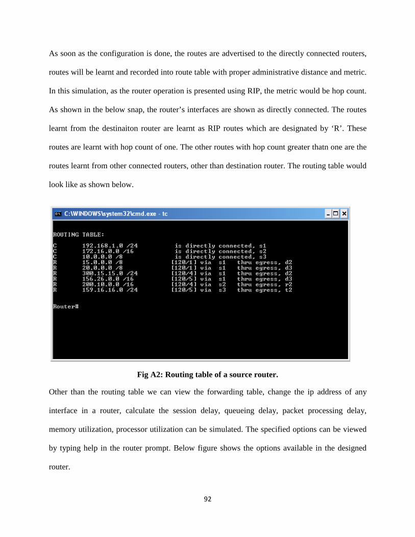
92
As soon as the configuration is done, the routes are advertised to the directly connected routers,
routes will be learnt and recorded into route table with proper administrative distance and metric.
In this simulation, as the router operation is presented using RIP, the metric would be hop count.
As shown in the below snap, the router’s interfaces are shown as directly connected. The routes
learnt from the destinaiton router are learnt as RIP routes which are designated by ‘R’. These
routes are learnt with hop count of one. The other routes with hop count greater thatn one are the
routes learnt from other connected routers, other than destination router. The routing table would
look like as shown below.
Fig A2: Routing table of a source router.
Other than the routing table we can view the forwarding table, change the ip address of any
interface in a router, calculate the session delay, queueing delay, packet processing delay,
memory utilization, processor utilization can be simulated. The specified options can be viewed
by typing help in the router prompt. Below figure shows the options available in the designed
router.
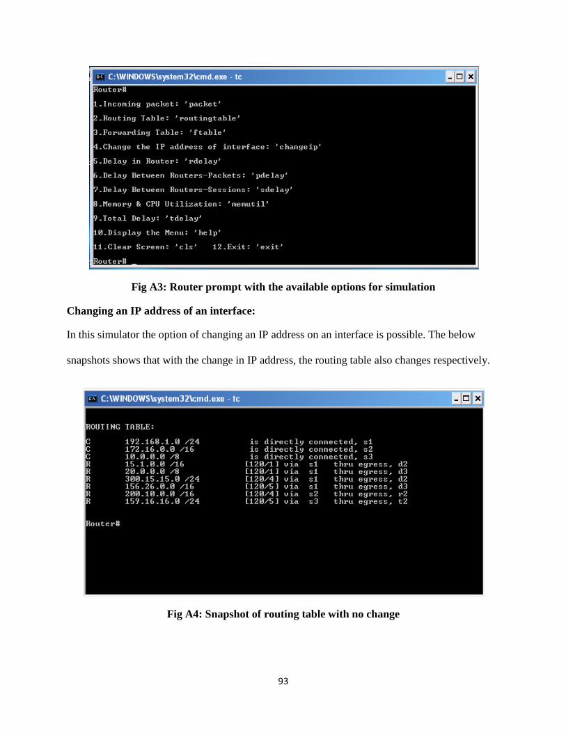
93
Fig A3: Router prompt with the available options for simulation
Changing an IP address of an interface:
In this simulator the option of changing an IP address on an interface is possible. The below
snapshots shows that with the change in IP address, the routing table also changes respectively.
Fig A4: Snapshot of routing table with no change
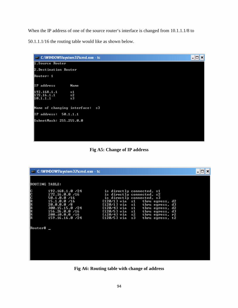
94
When the IP address of one of the source router‘s interface is changed from 10.1.1.1/8 to
50.1.1.1/16 the routing table would like as shown below.
Fig A5: Change of IP address
Fig A6: Routing table with change of address

95
In the simulator during the packet transfer operation, the source IP address and destination IP
address need to be specified. So the specification of these parameters is as shown below.
Fig 7: Snapshot showing the packet transition parameters
As the packets come in they are checked with the existing interface cache table on the incoming
interface. If a route is present, then the session is established with the outgoing interface of the
next hop router and the packet is forwarded. During this process the forwarding table is formed.
The forwarding table on the source router holds the destination router’s interface’s buffers which
are obtained by TCP negotiation and the source router’s ingress interface’s buffer details for the
incoming packets. So the forwarding table generation process is shown in the below snap shots.
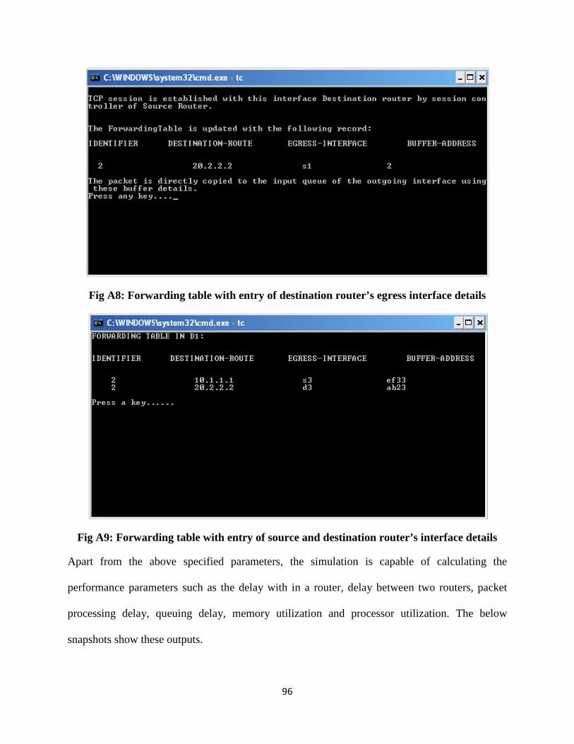
96
Fig A8: Forwarding table with entry of destination router’s egress interface details
Fig A9: Forwarding table with entry of source and destination router’s interface details
Apart from the above specified parameters, the simulation is capable of calculating the
performance parameters such as the delay with in a router, delay between two routers, packet
processing delay, queuing delay, memory utilization and processor utilization. The below
snapshots show these outputs.

97
Fig A10: Snapshot of Queuing delay calculation
Fig A11: Snapshot of packet delay and session delay calculation
In the above snapshot although the packet delay is calculated for total number of packets, the
delay is more for the first packet and from the second packet switching process takes place,
which reduces the delay.

98
Fig A11: Snapshot of the Memory and CPU utilization
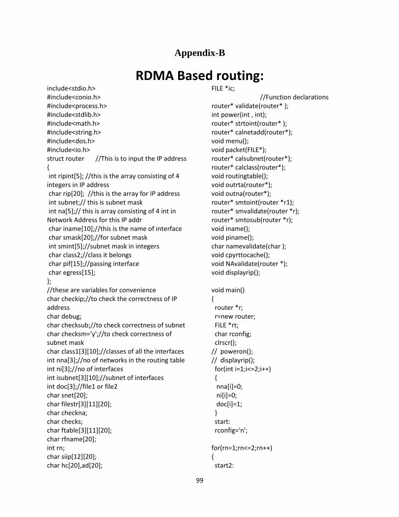
99
Appendix-B
RDMA Based routing: include<stdio.h>
#include<conio.h>
#include<process.h>
#include<stdlib.h>
#include<math.h>
#include<string.h>
#include<dos.h>
#include<io.h>
struct router //This is to input the IP address
{
int ripint[5]; //this is the array consisting of 4
integers in IP address
char rip[20]; //this is the array for IP address
int subnet;// this is subnet mask
int na[5];// this is array consisting of 4 int in
Network Address for this IP addr
char iname[10];//this is the name of interface
char smask[20];//for subnet mask
int smint[5];//subnet mask in integers
char class2;//class it belongs
char pif[15];//passing interface
char egress[15];
};
//these are variables for convenience
char checkip;//to check the correctness of IP
address
char debug;
char checksub;//to check correctness of subnet
char checksm='y';//to check correctness of
subnet mask
char class1[3][10];//classes of all the interfaces
int nna[3];//no of networks in the routing table
int ni[3];//no of interfaces
int isubnet[3][10];//subnet of interfaces
int doc[3];//file1 or file2
char snet[20];
char filestr[3][11][20];
char checkna;
char checks;
char ftable[3][11][20];
char rfname[20];
int rn;
char siip[12][20];
char hc[20],ad[20];
FILE *ic;
//Function declarations
router* validate(router* );
int power(int , int);
router* strtoint(router* );
router* calnetadd(router*);
void menu();
void packet(FILE*);
router* calsubnet(router*);
router* calclass(router*);
void routingtable();
void outrta(router*);
void outna(router*);
router* smtoint(router *r1);
router* smvalidate(router *r);
router* smtosub(router *r);
void iname();
void piname();
char namevalidate(char );
void cpyrttocache();
void NAvalidate(router *);
void displayrip();
void main()
{
router *r;
r=new router;
FILE *rt;
char rconfig;
clrscr();
// poweron();
// displayrip();
for(int i=1;i<=2;i++)
{
nna[i]=0;
ni[i]=0;
doc[i]=1;
}
start:
rconfig='n';
for(rn=1;rn<=2;rn++)
{
start2:
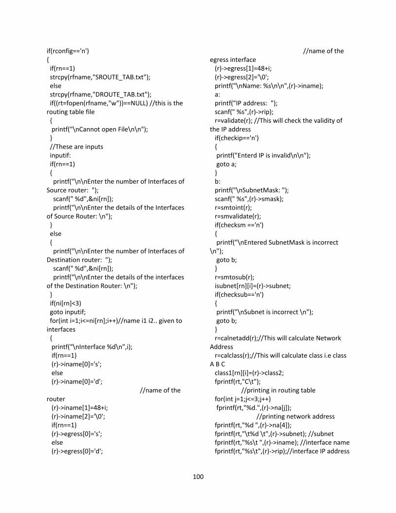
100
if(rconfig=='n')
{
if(rn==1)
strcpy(rfname,"SROUTE_TAB.txt");
else
strcpy(rfname,"DROUTE_TAB.txt");
if((rt=fopen(rfname,"w"))==NULL) //this is the
routing table file
{
printf("\nCannot open File\n\n");
}
//These are inputs
inputif:
if(rn==1)
{
printf("\n\nEnter the number of Interfaces of
Source router: ");
scanf(" %d",&ni[rn]);
printf("\n\nEnter the details of the Interfaces
of Source Router: \n");
}
else
{
printf("\n\nEnter the number of Interfaces of
Destination router: ");
scanf(" %d",&ni[rn]);
printf("\n\nEnter the details of the interfaces
of the Destination Router: \n");
}
if(ni[rn]<3)
goto inputif;
for(int i=1;i<=ni[rn];i++)//name i1 i2.. given to
interfaces
{
printf("\nInterface %d\n",i);
if(rn==1)
(r)->iname[0]='s';
else
(r)->iname[0]='d';
//name of the
router
(r)->iname[1]=48+i;
(r)->iname[2]='\0';
if(rn==1)
(r)->egress[0]='s';
else
(r)->egress[0]='d';
//name of the
egress interface
(r)->egress[1]=48+i;
(r)->egress[2]='\0';
printf("\nName: %s\n\n",(r)->iname);
a:
printf("IP address: ");
scanf(" %s",(r)->rip);
r=validate(r); //This will check the validity of
the IP address
if(checkip=='n')
{
printf("Enterd IP is invalid\n\n");
goto a;
}
b:
printf("\nSubnetMask: ");
scanf(" %s",(r)->smask);
r=smtoint(r);
r=smvalidate(r);
if(checksm =='n')
{
printf("\nEntered SubnetMask is incorrect
\n");
goto b;
}
r=smtosub(r);
isubnet[rn][i]=(r)->subnet;
if(checksub=='n')
{
printf("\nSubnet is incorrect \n");
goto b;
}
r=calnetadd(r);//This will calculate Network
Address
r=calclass(r);//This will calculate class i.e class
A B C
class1[rn][i]=(r)->class2;
fprintf(rt,"C\t");
//printing in routing table
for(int j=1;j<=3;j++)
fprintf(rt,"%d.",(r)->na[j]);
//printing network address
fprintf(rt,"%d ",(r)->na[4]);
fprintf(rt,"\t%d \t",(r)->subnet); //subnet
fprintf(rt,"%s\t ",(r)->iname); //interface name
fprintf(rt,"%s\t",(r)->rip);//interface IP address
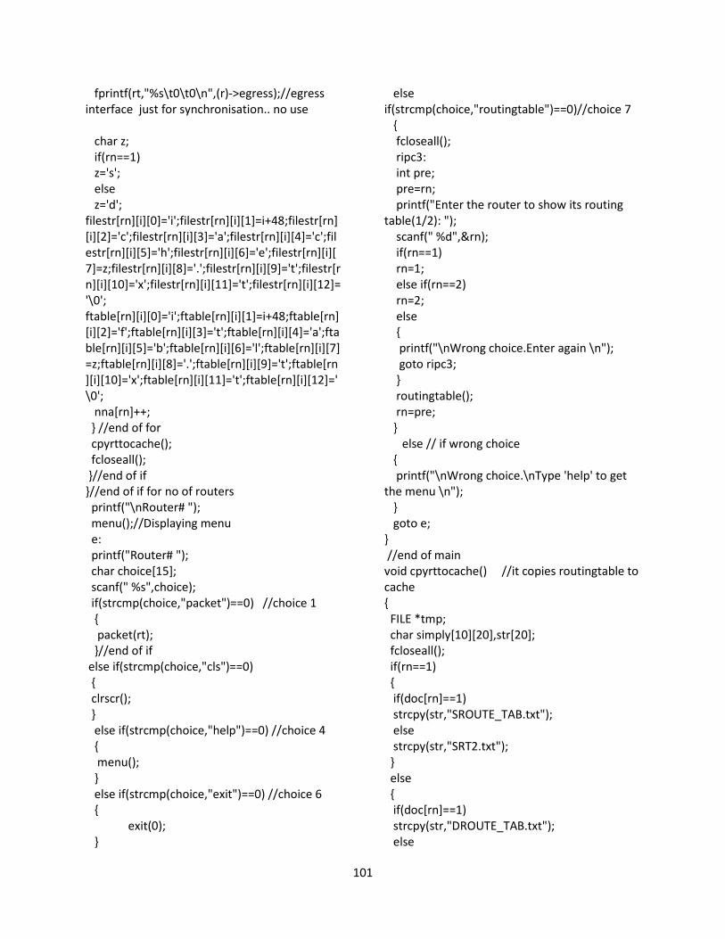
101
fprintf(rt,"%s\t0\t0\n",(r)->egress);//egress
interface just for synchronisation.. no use
char z;
if(rn==1)
z='s';
else
z='d';
filestr[rn][i][0]='i';filestr[rn][i][1]=i+48;filestr[rn]
[i][2]='c';filestr[rn][i][3]='a';filestr[rn][i][4]='c';fil
estr[rn][i][5]='h';filestr[rn][i][6]='e';filestr[rn][i][
7]=z;filestr[rn][i][8]='.';filestr[rn][i][9]='t';filestr[r
n][i][10]='x';filestr[rn][i][11]='t';filestr[rn][i][12]=
'\0';
ftable[rn][i][0]='i';ftable[rn][i][1]=i+48;ftable[rn]
[i][2]='f';ftable[rn][i][3]='t';ftable[rn][i][4]='a';fta
ble[rn][i][5]='b';ftable[rn][i][6]='l';ftable[rn][i][7]
=z;ftable[rn][i][8]='.';ftable[rn][i][9]='t';ftable[rn
][i][10]='x';ftable[rn][i][11]='t';ftable[rn][i][12]='
\0';
nna[rn]++;
} //end of for
cpyrttocache();
fcloseall();
}//end of if
}//end of if for no of routers
printf("\nRouter# ");
menu();//Displaying menu
e:
printf("Router# ");
char choice[15];
scanf(" %s",choice);
if(strcmp(choice,"packet")==0) //choice 1
{
packet(rt);
}//end of if
else if(strcmp(choice,"cls")==0)
{
clrscr();
}
else if(strcmp(choice,"help")==0) //choice 4
{
menu();
}
else if(strcmp(choice,"exit")==0) //choice 6
{
exit(0);
}
else
if(strcmp(choice,"routingtable")==0)//choice 7
{
fcloseall();
ripc3:
int pre;
pre=rn;
printf("Enter the router to show its routing
table(1/2): ");
scanf(" %d",&rn);
if(rn==1)
rn=1;
else if(rn==2)
rn=2;
else
{
printf("\nWrong choice.Enter again \n");
goto ripc3;
}
routingtable();
rn=pre;
}
else // if wrong choice
{
printf("\nWrong choice.\nType 'help' to get
the menu \n");
}
goto e;
}
//end of main
void cpyrttocache() //it copies routingtable to
cache
{
FILE *tmp;
char simply[10][20],str[20];
fcloseall();
if(rn==1)
{
if(doc[rn]==1)
strcpy(str,"SROUTE_TAB.txt");
else
strcpy(str,"SRT2.txt");
}
else
{
if(doc[rn]==1)
strcpy(str,"DROUTE_TAB.txt");
else
102
strcpy(str,"DRT2.txt");
}
if((tmp=fopen(str,"r"))==NULL) //this is the
routing table file
{
printf("\nCannot open file in cpyrttocache to
read\n\n");
}
for(int i=1;i<=ni[rn];i++)
{
ic=fopen(filestr[rn][i],"w"); //this is the cache
file
while(!feof(tmp))
{
fscanf(tmp," %s %s %s %s %s
%s%s%s",simply[1],simply[2],simply[3],simply[4
],simply[5],simply[6],simply[7],simply[8]);
fprintf(ic,"%s\t%s\t%s\t%s\t%s\t%s\t%s\t%s\n"
,simply[1],simply[2],simply[3],simply[4],simply[
5],simply[6]);
for(int j=1;j<=6;j++)
strcpy(simply[j],NULL);
}
fclose(ic);
rewind(tmp);
}
fcloseall();
}//end of cpyrttocache
//converts char subnet mask into integers
router* smtoint(router *r1) //The input is in
string.So it converts each octate to string
{
int j,t=0,t2,d,temp,l;
l=strlen(r1->smask);
for(j=1;j<=3;j++) //only first 3 ints in IP addr
{
t2=t;
d=0;
while(r1->smask[t2]!='.')// to see whether
ther are 2 digits or 3 digits after '.'
{
d++;
t2++;
}
temp=0;
while(r1->smask[t]!='.')
{
temp = temp + (r1->smask[t]-
48)*power(10,d-1); //converting into integer
t++;
d--;
}//end of while
t++;
r1->smint[j]=temp;
}//end of for1
t2=t;
d=0;
while(t2<l) //find no of digits in last octet
{
d++;
t2++;
}
temp=0;
while(t<l)//this is for 4th integer
{
temp=temp+(r1->smask[t]-48)*power(10,d-
1);
t++;
d--;
}//end of while
r1->smint[j]=temp;
return r1;
}//end of smtoint
router* smvalidate(router *r) //to validate IP
string and convert string to integer
{
int temp,j,d,t2,l;
l=strlen(r->smask); //string length
if(l>15 || l<7) //if string length is <7 and >15
it will not accept
{
checksm='n';
return r;
}
else
checksm='y';
t2=0;
d=0;
while(t2<l) //Counting no. of dots(.) in the IP
address
{
if(r->smask[t2]=='.')
d++;
t2++;
}
103
if(d!=3) //if '.' are not equal to 3 in IP
addresss,it will reject it
{
checksm='n';
return r;
}
else
checksm='y';
r=smtoint(r); //converting string to integer
for(j=1;j<=3;j++) //if any of the integers are
greater than 255 it will reject
{
if(r->smint[j]>255)
{
checksm='n';
return r;
}
else
checksm='y';
}
if(r->smint[1]!=255) //first octet in subnetmask
{
checksm='n';
return r;
}
//to ensure that the octets after an
octet(value<255) are all zero
for(int i=1;i<=4;i++)
{
if(r->smint[i] < 255)
{
for(j=i+1;j<=4;j++)
{
if(r->smint[j]!=0)
{
checksm='n';
return r;
}
}//end of for in
}
}//end of for out
return r;
}//end of smvalidate
router* smtosub(router *r)//this will convert
subnetmask to subnet
{
int octet,ov,s;
for(int i=1;i<=4;i++) //check which octet has
value less than or equal to 255
{
if(r->smint[i]>0 && r->smint[i]<=255)
{
ov=r->smint[i];
octet=i;
}
}//end of for
//assigns subnet according to value in
the octet
if(ov==128)
r->subnet=(octet-1)*8+1;
else if(ov==192)
r->subnet=(octet-1)*8+2;
else if(ov==224)
r->subnet=(octet-1)*8+3;
else if(ov==240)
r->subnet=(octet-1)*8+4;
else if(ov==248)
r->subnet=(octet-1)*8+5;
else if(ov==252)
r->subnet=(octet-1)*8+6;
else if(ov==254)
r->subnet=(octet-1)*8+7;
else if(ov==255)
r->subnet=(octet-1)*8+8;
else //to ensure that the subnet mask
consists above numbers only
{
checksub='n';
return r;
}
printf("\nSubnet: %d\n",r->subnet);
if(r->subnet>30) //validate the subnet. Max
possible is 30
{
checksub='n';
printf("Entered subnet is invalid.Maximum
possible subnet is 30 \n\n");
return r;
}
if(r->ripint[1]>=0 && r->ripint[1]<127)
{
if(r->subnet<8) // Class A subnet is >8
{
104
printf("Entered IP is class A. This will not
have subnet less than 8\n\n");
checksub='n';
return r;
}
else
{
checksub='y';
}
}
if(r->ripint[1]>=128 && r->ripint[1]<192)
{
if(r->subnet<16) //Class B subnet is >16
{
checksub='n';
printf("Entered IP is class B. This will not
have subnet less than 16\n\n");
return r;
}
else
{
checksub='y';
}
}
if(r->ripint[1]>=192 && r->ripint[1]<256)
{
if(r->subnet<24) //Class C subnet is >24
{
checksub='n';
printf("Entered IP is class C. This will not
have subnet less than 24\n\n");
return r;
}
else
{
checksub='y';
}
}
return r;
}//end of smtosub
//to validate the entered interface
name
char namevalidate(char *s)
{
if(strlen(s)!=2) //the length of name should be
2 only
{
printf("\nWrong name of interface\n\n");
return ('n');
}
else if(s[0]!='s' && s[0]!='d') //first letter should
be 's' or 'd'
{
printf("\nWrong name of interface\n\n");
return('n');
}
else if(!(s[1] >='1' && s[1] <='9'))//second
letter should be between 1 and 9
{
printf("\nWrong name of interface\n\n");
return('n');
}
else if( (s[1] - 48)> ni[rn]) //if out of bound of
interfaces
{
printf("\nWrong name of interface\n\n");
return('n');
}
else if( rn==1)
{
if(s[0]!='s')
{
printf("\nWrong name of interface\n\n");
return('n');
}
}
else if( rn==2)
{
if(s[0]!='d')
{
printf("\nWrong name of interface\n\n");
return('n');
}
}
else
return('y');
return('y');
}//end of namevalidate
//to display the name and IP address of
inteface
void iname()
{
FILE *fp;
router *r;
char c[3],str[20];
r=new router;

105
if(rn==1)
{
strcpy(rfname,"SROUTE_TAB.txt");
strcpy(str,"SRT2.txt");
}
else
{
strcpy(rfname,"DROUTE_TAB.txt");
strcpy(str,"DRT2.txt");
}
if(doc[rn]==1) //to check whether file1 or
file2
{
if((fp=fopen(rfname,"r"))==NULL)
printf("Cannot open file \n");
}
else
{
if((fp=fopen(str,"r"))==NULL)
printf("Cannot open file \n");
}
printf("\nIP address \t Name \n\n");
//displaying names and IP addr.
for(int i=1;i<=ni[rn];i++)
{
fscanf(fp,"%s %s %s %s %s %s %s %s",c,r-
>na,snet,r->iname,r->pif,r->egress,ad,hc);
printf("%s \t %s \n",r->pif,r->iname);
}
printf("\n");
fclose(fp);
delete r;
} //end of iname
//to display the name and IP address of
inteface
void piname()
{
FILE *fp;
router *r;
char c[3],str[20];
r=new router;
if(rn==1)
{
strcpy(rfname,"SROUTE_TAB.txt");
strcpy(str,"SRT2.txt");
}
else
{
strcpy(rfname,"DROUTE_TAB.txt");
strcpy(str,"DRT2.txt");
}
if(doc[rn]==1) //to check whether file1 or
file2
{
if((fp=fopen(rfname,"r"))==NULL)
printf("Cannot open file \n");
}
else
{
if((fp=fopen(str,"r"))==NULL)
printf("Cannot open file \n");
}
printf("\nIP address \t Name \n\n");
//displaying names and IP addr.
for(int i=1;i<=ni[rn];i++)
{
fscanf(fp,"%s %s %s %s %s %s %s %s",c,r-
>na,snet,r->iname,r->pif,r->egress,ad,hc);
strcpy(siip[i],r->pif);
if(strcmp(r->iname,"s1")!=0)
printf("%s \t %s \n",r->pif,r->iname);
}
printf("\n");
fclose(fp);
delete r;
} //end of piname
router* validate(router *r) //to validate IP
string and convert string to integer
{
int temp,j,d,t2,l;
l=strlen(r->rip); //string length
if(l>15 || l<7) //if string length is <7 and >15
it will not accept
{
checkip='n';
return r;
}
else
checkip='y';
t2=0;
d=0;
while(t2<l) //Counting no. of dots(.) in the IP
address
{
if(r->rip[t2]=='.')
106
d++;
t2++;
}
if(d!=3) //if '.' are not equal to 3 in IP
addresss,it will reject it
{
checkip='n';
return r;
}
else
checkip='y';
r=strtoint(r); //converting string to integer
for(j=1;j<=4;j++) //if any of the integers are
greater than 255 it will reject
{
if(r->ripint[j]>255)
{
checkip='n';
return r;
}
else
checkip='y';
}
return r;
}//end of validate
router* strtoint(router *r1) //The input is in
string.So it converts each octate to string
{
int j,t=0,t2,d,temp,l;
l=strlen(r1->rip);
for(j=1;j<=3;j++) //only first 3 ints in IP addr
{
t2=t;
d=0;
while(r1->rip[t2]!='.')// to see whether ther
are 2 digits or 3 digits after '.'
{
d++;
t2++;
}
temp=0;
while(r1->rip[t]!='.')
{
temp=temp+(r1->rip[t]-48)*power(10,d-1);
//converting into integer
t++;
d--;
}//end of while
t++;
r1->ripint[j]=temp;
}//end of for1
t2=t;
d=0;
while(t2<l)
{
d++;
t2++;
}
temp=0;
while(t<l)//this is for 4th integer
{
temp=temp+(r1->rip[t]-48)*power(10,d-1);
t++;
d--;
}//end of while
r1->ripint[j]=temp;
return r1;
}//end of strtoint
router* calnetadd(router *r) //to calculate
network address from IP address
{
int nab,hab,nhost,nnet,n,temp=0;
nab=r->subnet; //network address bits
// printf("nab: %d\n",nab);
hab=32-nab; //host address bits
while(hab>8)
{
hab=hab-8; //host address bits of the
particular octet
}
if( hab%8!=0)//checks whether hab is multiple
of 8
{
nhost=power(2,8-hab); // in the subnetted
octet,no. of hosts
nnet=power(2,hab);//in the octet, no. of
networks
n=(nab/8)+1;//to find which octet it is
for(int i=1;i<=nnet;i++) // searching for all
networks
{
if(r->ripint[n] >temp && r->ripint[n] <
(temp+nhost))
{
r->na[n]=temp; //assigning value to network
adddress octet which is subnetted
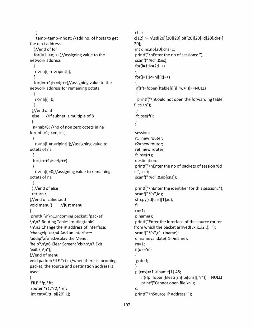
107
}
temp=temp+nhost; //add no. of hosts to get
the next address
}//end of for
for(i=1;i<n;i++)//assigning value to the
network address
{
r->na[i]=r->ripint[i];
}
for(i=n+1;i<=4;i++)//assigning value to the
network address for remaining octets
{
r->na[i]=0;
}
}//end of if
else //if subnet is multiple of 8
{
n=nab/8; //no of non zero octets in na
for(int i=1;i<=n;i++)
{
r->na[i]=r->ripint[i];//assigning value to
octets of na
}
for(i=n+1;i<=4;i++)
{
r->na[i]=0;//assigning value to remaining
octets of na
}
} //end of else
return r;
}//end of calnetadd
void menu() //just menu
{
printf("\n\n1.Incoming packet: 'packet'
\n\n2.Routing Table: 'routingtable'
\n\n3.Change the IP address of interface:
'changeip'\n\n4.Add an interface:
'addip'\n\n5.Display the Menu:
'help'\n\n6.Clear Screen: 'cls'\n\n7.Exit:
'exit'\n\n");
}//end of menu
void packet(FILE *rt) //when there is incoming
packet, the source and destination address is
used
{
FILE *fp,*ft;
router *r1,*r2,*ref;
int cnt=0,ttl,pi[20],i,j;
char
c[12],r='n',sd[20][20][20],oif[20][20],id[20],drei[
20];
int d,ns,np[20],cns=1;
printf("\nEnter the no of sessions: ");
scanf(" %d",&ns);
for(i=1;i<=2;i++)
{
for(j=1;j<=ni[i];j++)
{
if((ft=fopen(ftable[i][j],"w+"))==NULL)
{
printf("\nCould not open the forwarding table
files \n");
}
fclose(ft);
}
}
session:
r1=new router;
r2=new router;
ref=new router;
fclose(rt);
destination:
printf("\nEnter the no of packets of session %d
: ",cns);
scanf(" %d",&np[cns]);
printf("\nEnter the identifier for this session: ");
scanf(" %s",id);
strcpy(sd[cns][1],id);
f:
rn=1;
piname();
printf("Enter the Interface of the source router
from which the packet arrived(Ex:i1,i2..): ");
scanf(" %s",r1->iname);
d=namevalidate(r1->iname);
rn=1;
if(d=='n')
{
goto f;
}
pi[cns]=r1->iname[1]-48;
if((fp=fopen(filestr[rn][pi[cns]],"r"))==NULL)
printf("Cannot open file \n");
c:
printf("\nSource IP address: ");
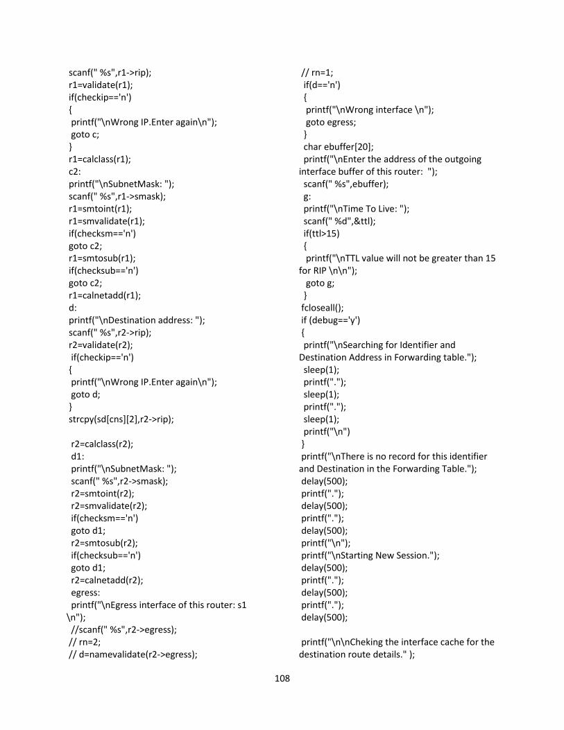
108
scanf(" %s",r1->rip);
r1=validate(r1);
if(checkip=='n')
{
printf("\nWrong IP.Enter again\n");
goto c;
}
r1=calclass(r1);
c2:
printf("\nSubnetMask: ");
scanf(" %s",r1->smask);
r1=smtoint(r1);
r1=smvalidate(r1);
if(checksm=='n')
goto c2;
r1=smtosub(r1);
if(checksub=='n')
goto c2;
r1=calnetadd(r1);
d:
printf("\nDestination address: ");
scanf(" %s",r2->rip);
r2=validate(r2);
if(checkip=='n')
{
printf("\nWrong IP.Enter again\n");
goto d;
}
strcpy(sd[cns][2],r2->rip);
r2=calclass(r2);
d1:
printf("\nSubnetMask: ");
scanf(" %s",r2->smask);
r2=smtoint(r2);
r2=smvalidate(r2);
if(checksm=='n')
goto d1;
r2=smtosub(r2);
if(checksub=='n')
goto d1;
r2=calnetadd(r2);
egress:
printf("\nEgress interface of this router: s1
\n");
//scanf(" %s",r2->egress);
// rn=2;
// d=namevalidate(r2->egress);
// rn=1;
if(d=='n')
{
printf("\nWrong interface \n");
goto egress;
}
char ebuffer[20];
printf("\nEnter the address of the outgoing
interface buffer of this router: ");
scanf(" %s",ebuffer);
g:
printf("\nTime To Live: ");
scanf(" %d",&ttl);
if(ttl>15)
{
printf("\nTTL value will not be greater than 15
for RIP \n\n");
goto g;
}
fcloseall();
if (debug=='y')
{
printf("\nSearching for Identifier and
Destination Address in Forwarding table.");
sleep(1);
printf(".");
sleep(1);
printf(".");
sleep(1);
printf("\n")
}
printf("\nThere is no record for this identifier
and Destination in the Forwarding Table.");
delay(500);
printf(".");
delay(500);
printf(".");
delay(500);
printf("\n");
printf("\nStarting New Session.");
delay(500);
printf(".");
delay(500);
printf(".");
delay(500);
printf("\n\nCheking the interface cache for the
destination route details." );
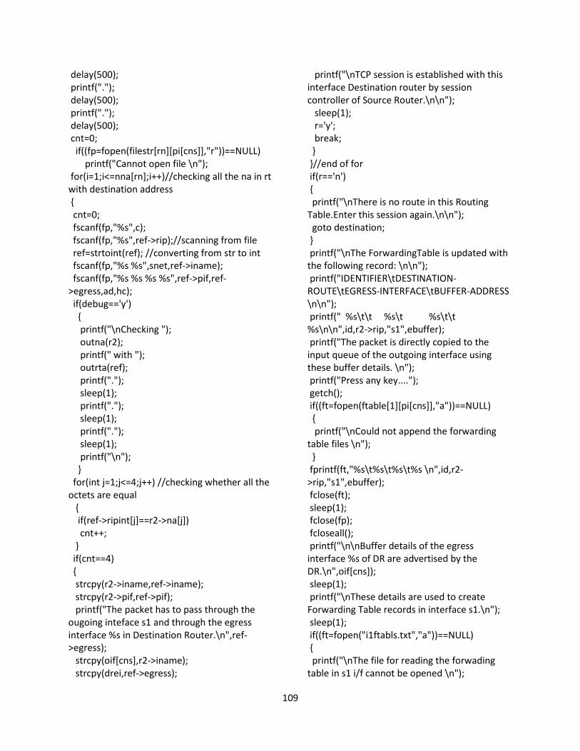
109
delay(500);
printf(".");
delay(500);
printf(".");
delay(500);
cnt=0;
if((fp=fopen(filestr[rn][pi[cns]],"r"))==NULL)
printf("Cannot open file \n");
for(i=1;i<=nna[rn];i++)//checking all the na in rt
with destination address
{
cnt=0;
fscanf(fp,"%s",c);
fscanf(fp,"%s",ref->rip);//scanning from file
ref=strtoint(ref); //converting from str to int
fscanf(fp,"%s %s",snet,ref->iname);
fscanf(fp,"%s %s %s %s",ref->pif,ref-
>egress,ad,hc);
if(debug=='y')
{
printf("\nChecking ");
outna(r2);
printf(" with ");
outrta(ref);
printf(".");
sleep(1);
printf(".");
sleep(1);
printf(".");
sleep(1);
printf("\n");
}
for(int j=1;j<=4;j++) //checking whether all the
octets are equal
{
if(ref->ripint[j]==r2->na[j])
cnt++;
}
if(cnt==4)
{
strcpy(r2->iname,ref->iname);
strcpy(r2->pif,ref->pif);
printf("The packet has to pass through the
ougoing inteface s1 and through the egress
interface %s in Destination Router.\n",ref-
>egress);
strcpy(oif[cns],r2->iname);
strcpy(drei,ref->egress);
printf("\nTCP session is established with this
interface Destination router by session
controller of Source Router.\n\n");
sleep(1);
r='y';
break;
}
}//end of for
if(r=='n')
{
printf("\nThere is no route in this Routing
Table.Enter this session again.\n\n");
goto destination;
}
printf("\nThe ForwardingTable is updated with
the following record: \n\n");
printf("IDENTIFIER\tDESTINATION-
ROUTE\tEGRESS-INTERFACE\tBUFFER-ADDRESS
\n\n");
printf(" %s\t\t %s\t %s\t\t
%s\n\n",id,r2->rip,"s1",ebuffer);
printf("The packet is directly copied to the
input queue of the outgoing interface using
these buffer details. \n");
printf("Press any key....");
getch();
if((ft=fopen(ftable[1][pi[cns]],"a"))==NULL)
{
printf("\nCould not append the forwarding
table files \n");
}
fprintf(ft,"%s\t%s\t%s\t%s \n",id,r2-
>rip,"s1",ebuffer);
fclose(ft);
sleep(1);
fclose(fp);
fcloseall();
printf("\n\nBuffer details of the egress
interface %s of DR are advertised by the
DR.\n",oif[cns]);
sleep(1);
printf("\nThese details are used to create
Forwarding Table records in interface s1.\n");
sleep(1);
if((ft=fopen("i1ftabls.txt","a"))==NULL)
{
printf("\nThe file for reading the forwading
table in s1 i/f cannot be opened \n");
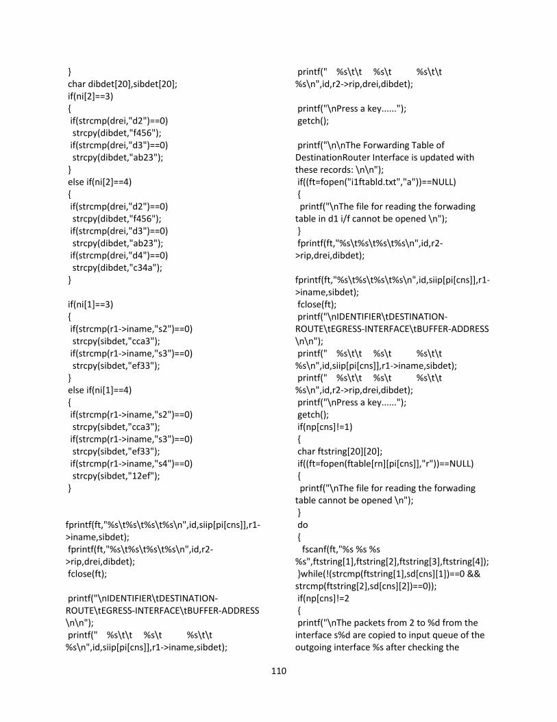
110
}
char dibdet[20],sibdet[20];
if(ni[2]==3)
{
if(strcmp(drei,"d2")==0)
strcpy(dibdet,"f456");
if(strcmp(drei,"d3")==0)
strcpy(dibdet,"ab23");
}
else if(ni[2]==4)
{
if(strcmp(drei,"d2")==0)
strcpy(dibdet,"f456");
if(strcmp(drei,"d3")==0)
strcpy(dibdet,"ab23");
if(strcmp(drei,"d4")==0)
strcpy(dibdet,"c34a");
}
if(ni[1]==3)
{
if(strcmp(r1->iname,"s2")==0)
strcpy(sibdet,"cca3");
if(strcmp(r1->iname,"s3")==0)
strcpy(sibdet,"ef33");
}
else if(ni[1]==4)
{
if(strcmp(r1->iname,"s2")==0)
strcpy(sibdet,"cca3");
if(strcmp(r1->iname,"s3")==0)
strcpy(sibdet,"ef33");
if(strcmp(r1->iname,"s4")==0)
strcpy(sibdet,"12ef");
}
fprintf(ft,"%s\t%s\t%s\t%s\n",id,siip[pi[cns]],r1-
>iname,sibdet);
fprintf(ft,"%s\t%s\t%s\t%s\n",id,r2-
>rip,drei,dibdet);
fclose(ft);
printf("\nIDENTIFIER\tDESTINATION-
ROUTE\tEGRESS-INTERFACE\tBUFFER-ADDRESS
\n\n");
printf(" %s\t\t %s\t %s\t\t
%s\n",id,siip[pi[cns]],r1->iname,sibdet);
printf(" %s\t\t %s\t %s\t\t
%s\n",id,r2->rip,drei,dibdet);
printf("\nPress a key......");
getch();
printf("\n\nThe Forwarding Table of
DestinationRouter Interface is updated with
these records: \n\n");
if((ft=fopen("i1ftabld.txt","a"))==NULL)
{
printf("\nThe file for reading the forwading
table in d1 i/f cannot be opened \n");
}
fprintf(ft,"%s\t%s\t%s\t%s\n",id,r2-
>rip,drei,dibdet);
fprintf(ft,"%s\t%s\t%s\t%s\n",id,siip[pi[cns]],r1-
>iname,sibdet);
fclose(ft);
printf("\nIDENTIFIER\tDESTINATION-
ROUTE\tEGRESS-INTERFACE\tBUFFER-ADDRESS
\n\n");
printf(" %s\t\t %s\t %s\t\t
%s\n",id,siip[pi[cns]],r1->iname,sibdet);
printf(" %s\t\t %s\t %s\t\t
%s\n",id,r2->rip,drei,dibdet);
printf("\nPress a key......");
getch();
if(np[cns]!=1)
{
char ftstring[20][20];
if((ft=fopen(ftable[rn][pi[cns]],"r"))==NULL)
{
printf("\nThe file for reading the forwading
table cannot be opened \n");
}
do
{
fscanf(ft,"%s %s %s
%s",ftstring[1],ftstring[2],ftstring[3],ftstring[4]);
}while(!(strcmp(ftstring[1],sd[cns][1])==0 &&
strcmp(ftstring[2],sd[cns][2])==0));
if(np[cns]!=2
{
printf("\nThe packets from 2 to %d from the
interface s%d are copied to input queue of the
outgoing interface %s after checking the
111
forwarding table of the incoming interface
s%d.",np[cns],pi[cns],oif[cns],pi[cns]);
sleep(1);
printf(".");
sleep(1);
printf(".");
sleep(1);
printf("\n");
}
else
{
printf("\nThe 2nd packet from the interface
si%d is copied to input queue of the outgoing
interface %s after checking the forwarding table
of the incoming interface
si%d.",np[cns],pi[cns],ftstring[3],pi[cns]);
sleep(1);
printf(".");
sleep(1);
printf(".");
sleep(1);
printf("\n");
}
printf("IDENTIFIER\tDESTINATION-
ROUTE\tEGRESS-INTERFACE\tBUFFER-ADDRESS
\n\n");
printf(" %s\t\t %s\t %s\t\t
%s\n\n",ftstring[1],ftstring[2],ftstring[3],ftstring
[4]);
} //end of if for session having more no of
packets
delete r1,r2,ref;
printf("\n\nThe TTL value is decreased from %d
to %d \n\n",ttl,ttl-1);
ttl=ttl-1;
if(cns!=ns)
{
cns++;
goto session;
}
}//end of packet
void outrta(router *r) //output ip address
{
for(int i=1;i<=3;i++)
{
printf("%d.",r->ripint[i]);
}
printf("%d",r->ripint[4]);
}//end of outrta
void outna(router *r) //output network address
{
for(int i=1;i<=3;i++)
{
printf("%d.",r->na[i]);
}
printf("%d",r->na[4]);
}//end of outna
router* calsubnet(router *r) // to calculate
subnet
{
int t;
t=r->iname[1]-48;
if(r->class2 == class1[rn][t]) //checking class of
an IP address with class of interface
{
r->subnet=isubnet[rn][t];//subnet is same as
subnet of incoming interface
if(debug=='y')
{
printf("\nThe IPaddress class is equal to class
of Interface\n");
sleep(1);
printf("Subnet is same as that of Interface\n");
}
}
//if class is not same as incoming interface class
else if(r->class2=='a') //if class a then subnet is
8
{
r->subnet=8;
if(debug=='y')
{
printf("Subnet is equal to the default subnet
of the class\n");
sleep(1);
}
}
else if(r->class2=='b')
{
r->subnet=16;
if(debug=='y')
{
printf("Subnet is equal to the default subnet
of the class\n");
sleep(1);
112
}
}
else
{
r->subnet=24;
if(debug=='y')
{
printf("Subnet is equal to the default subnet
of the class\n");
sleep(1);
}
}
return r;
}//end of cal subnet
router* calclass(router *r) //to calculate the
class
{
if(r->ripint[1] >=0 && r->ripint[1] <128)
{
r->class2 ='a';
}
if(r->ripint[1] >=128 && r->ripint[1] <192)
{
r->class2 ='b';
}
if(r->ripint[1] >=192 && r->ripint[1] <256)
{
r->class2 ='c';
}
if(debug=='y')
{
printf("\nThe IP address is of class %c\n",r-
>class2);
}
return r;
}//end of calclass
void routingtable() //This is to display Routing
table
{
FILE *fp1;
router *r;
char c[20],c1[20];
r=new router;
if(rn==1)
{
strcpy(c1,"SRT2.txt");
strcpy(rfname,"SROUTE_TAB.txt");
}
else
{
strcpy(c1,"DRT2.txt");
strcpy(rfname,"DROUTE_TAB.txt");
}
if(doc[rn]==1)
{
if((fp1=fopen(rfname,"r"))==NULL)
printf("Cannot open file \n");
}
else
{
if((fp1=fopen(c1,"r"))==NULL)
printf("Cannot open file \n");
}
printf("\n");
printf("No of NA: %d \n",nna[rn]);
for(int i=1;i<=nna[rn];i++)
{
fscanf(fp1,"%s",c);
printf("%s\t",c);
fscanf(fp1,"%s %s",r->rip,snet);
printf("%s /%s \t",r->rip,snet);
fscanf(fp1,"%s",r->iname);
fscanf(fp1,"%s %s %s %s",r->pif,r-
>egress,ad,hc);
//printf("through %s \t",r->pif);
if(strcmp(c,"R")==0)
{
printf("[%s,%s] via %s\t",ad,hc,r->iname);
printf(" thru egress, %s ",r->egress);
}
else
printf(" is directly connected, %s",r->iname);
printf("\n");
}
printf("\n\n");
delete r;
fclose(fp1);
}//end of routing table