Embed Size (px)
Citation preview

Emission catalyst solutions
for Euro 5 and beyond
www.ecocat.com
ECT 2011, New Delhi
November 9-10, 2011
Dr Toni Kinnunen
CTO, Ecocat Group
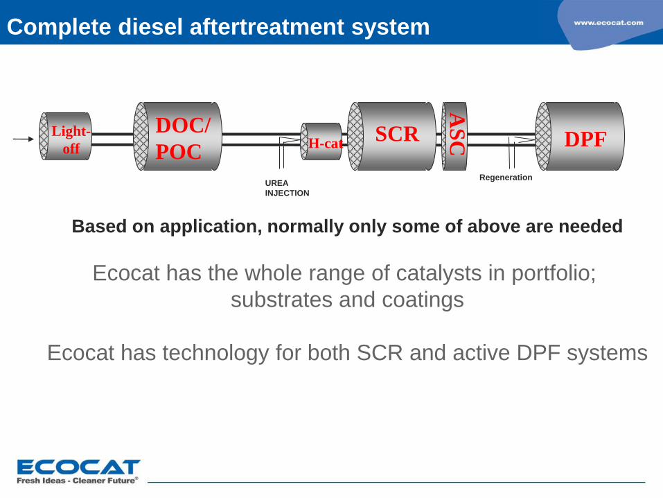
Complete diesel aftertreatment system
Based on application, normally only some of above are needed
Ecocat has the whole range of catalysts in portfolio;
substrates and coatings
Ecocat has technology for both SCR and active DPF systems
UREA
INJECTION
Regeneration
Light-
off
DOC/
POC SCR DPF
AS
C H-cat
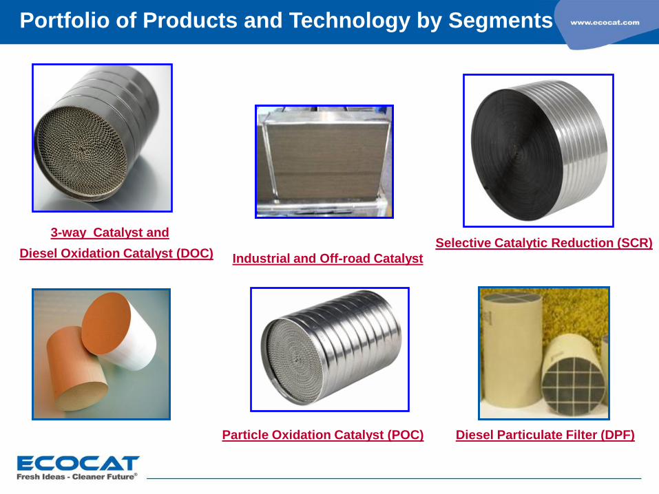
Portfolio of Products and Technology by Segments
Diesel Oxidation Catalyst (DOC)
Particle Oxidation Catalyst (POC) Diesel Particulate Filter (DPF)
Selective Catalytic Reduction (SCR) 3-way Catalyst and
Industrial and Off-road Catalyst
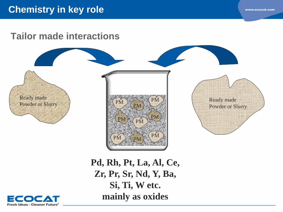
Tailor made interactions
PM
PM
PM PM
PM
PM
PM
PM
PM
Ready made
Powder or Slurry Ready made
Powder or Slurry
Pd, Rh, Pt, La, Al, Ce,
Zr, Pr, Sr, Nd, Y, Ba,
Si, Ti, W etc.
mainly as oxides
Chemistry in key role
Challenges in exhaust gas catalysis chemistry
Need for continuous development
- better cost efficiency (”better and cheaper”)
- improved durability (temperature, poisons)
Molecular scale modifications and analyses
Nanotechnology
Additional challenges
- impurities of poor biodiesels and batch-to-batch variations
- other alternative fuels require tailoring case by case
- regulations vs. dirty fuels (developing countries, off-road)
- city driving conditions in big cities
Chemistry in key role
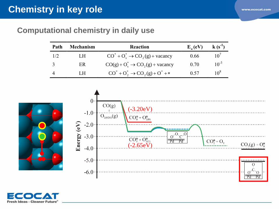
Path Mechanism Reaction aE (eV) k (s-1
)
1/2 LH vacancy(g)COOCO 2
*
s
* 0.66 107
3 ER vacancy(g)COOCO(g) 2
*
s 0.70 10-3
4 LH O(g)COOCO *
2
*
2
* 0.57 108
(-3.20eV)
(-2.65eV)
Computational chemistry in daily use
Chemistry in key role
SCR technology
PM reduction technologies
Natural gas catalysis
SCR systems
Urea Hydrolyser
V-SCR catalyst (and ASC)
dosing units and control
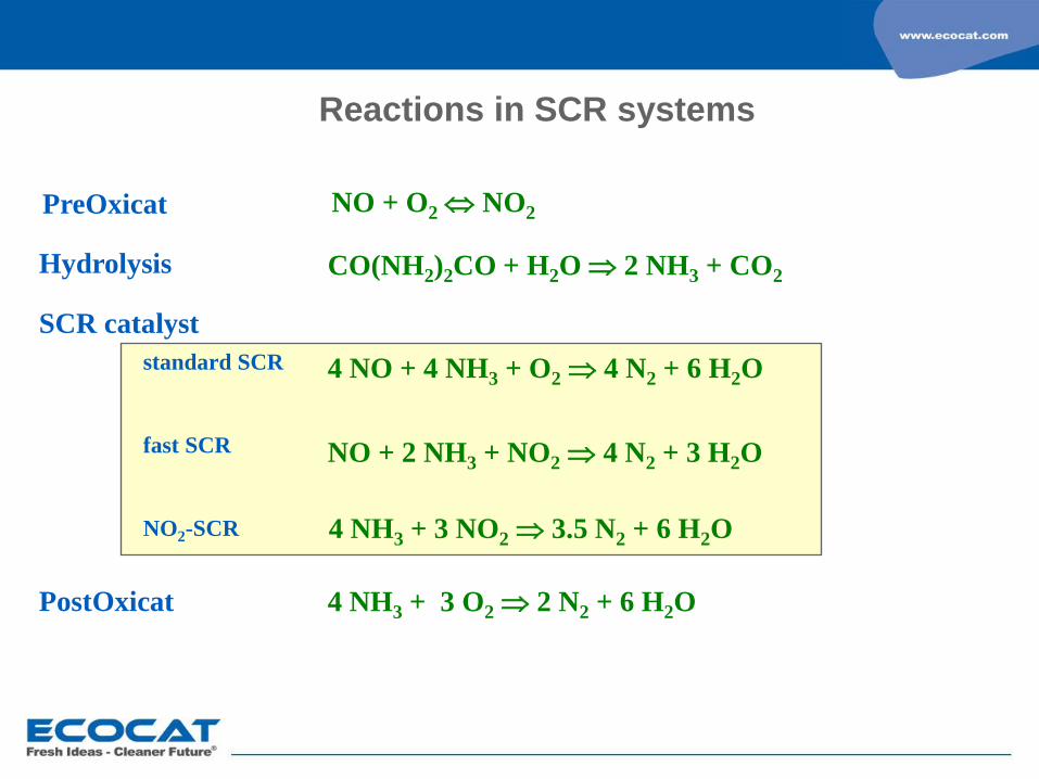
Reactions in SCR systems
PreOxicat
Hydrolysis
NO + O2 NO2
CO(NH2)2CO + H2O 2 NH3 + CO2
SCR catalyst
4 NO + 4 NH3 + O2 4 N2 + 6 H2O
NO + 2 NH3 + NO2 4 N2 + 3 H2O
PostOxicat 4 NH3 + 3 O2 2 N2 + 6 H2O
4 NH3 + 3 NO2 3.5 N2 + 6 H2O
standard SCR
fast SCR
NO2-SCR
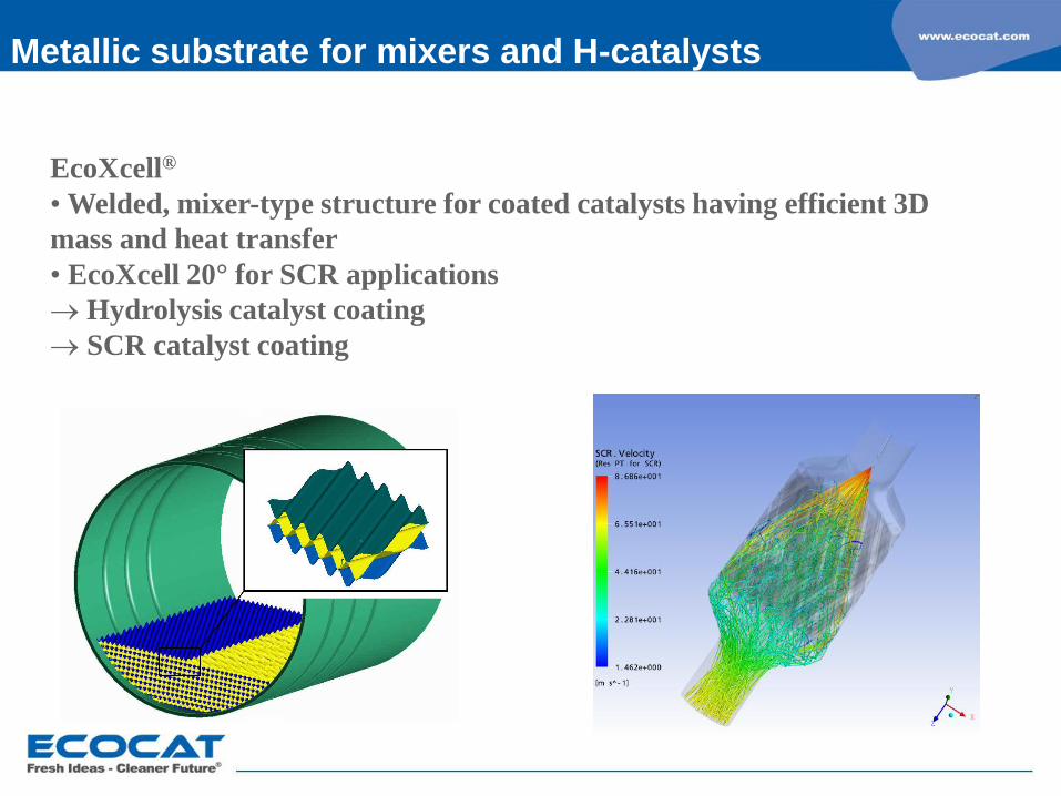
Metallic substrate for mixers and H-catalysts
EcoXcell®
• Welded, mixer-type structure for coated catalysts having efficient 3D
mass and heat transfer
• EcoXcell 20° for SCR applications
Hydrolysis catalyst coating
SCR catalyst coating
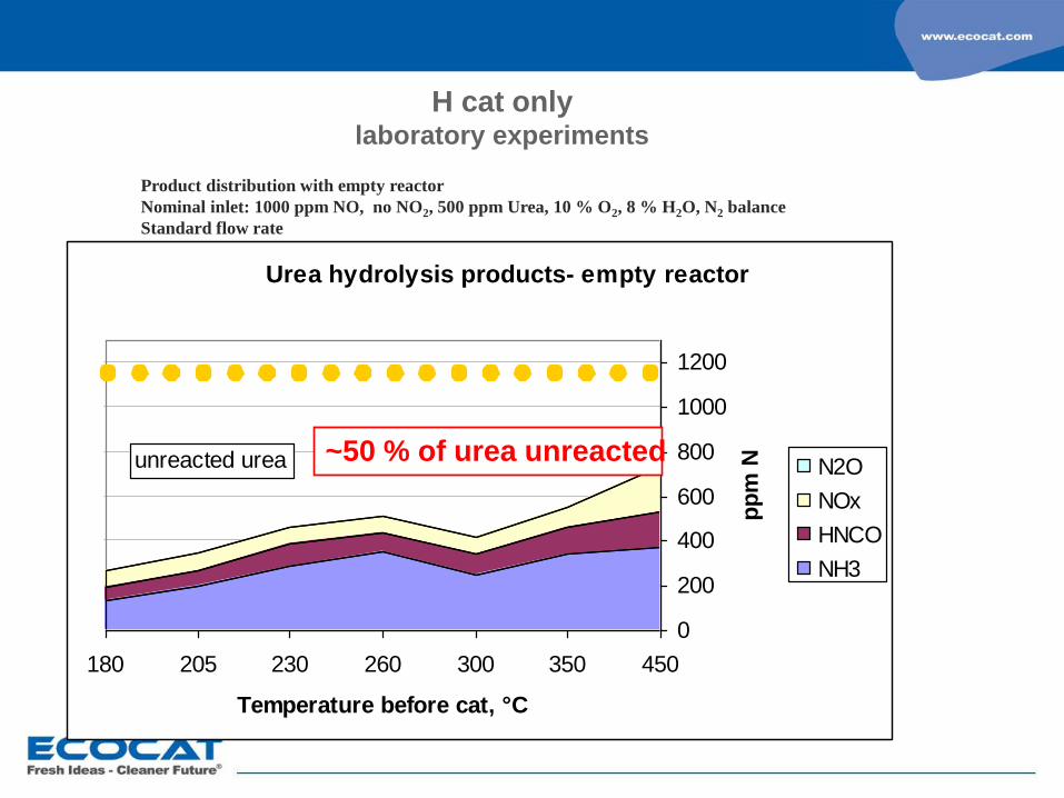
H cat only laboratory experiments
Product distribution with empty reactor
Nominal inlet: 1000 ppm NO, no NO2, 500 ppm Urea, 10 % O2, 8 % H2O, N2 balance
Standard flow rate
Urea hydrolysis products- empty reactor
0
200
400
600
800
1000
1200
450350300260230205180
Temperature before cat, °C
pp
m N N2O
NOx
HNCO
NH3
unreacted urea ~50 % of urea unreacted
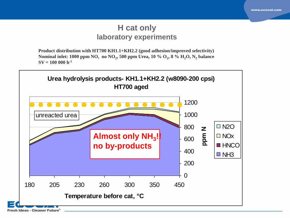
H cat only laboratory experiments
Product distribution with HT700 KH1.1+KH2.2 (good adhesion/improved selectivity)
Nominal inlet: 1000 ppm NO, no NO2, 500 ppm Urea, 10 % O2, 8 % H2O, N2 balance
SV = 100 000 h-1
Urea hydrolysis products- KH1.1+KH2.2 (w8090-200 cpsi)
HT700 aged
0
200
400
600
800
1000
1200
450350300260230205180
Temperature before cat, °C
pp
m N
N2O
NOx
HNCO
NH3
unreacted urea
Almost only NH3!!
no by-products
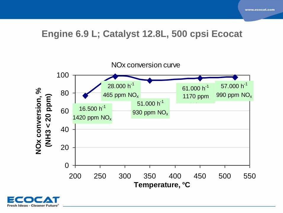
Engine 6.9 L; Catalyst 12.8L, 500 cpsi Ecocat
NOx conversion curve
0
20
40
60
80
100
200 250 300 350 400 450 500 550
Temperature, °C
NO
x c
on
ve
rsio
n, %
(NH
3 <
20
pp
m)
16.500 h-1
1420 ppm NOx
51.000 h-1
930 ppm NOx
61.000 h-1
1170 ppm
NOx
57.000 h-1
990 ppm NOx
28.000 h-1
465 ppm NOx

Urea-SCR engine results- MAN 6.9L, 15 h aged
KSCR2, 500 cpsi, 12.7L
0
10
20
30
40
50
60
70
80
90
100
200 250 300 350 400 450 500 550
Temperature, °C
Cri
teri
a N
Ox c
on
vers
ion
, %
(20 p
pm
NH
3)
KSCR2, 20 ppm NH3
KSCR2, 10 ppm NH3
16.500 h-1
30.000 h-1
51.000 h-1 61.000 h-1 58.000 h-1
Effect of NH3 slip criteria limit
No significant changes in performance
without any additional NH3 slip catalyst
0
10
20
30
40
50
60
70
80
90
100
200 250 300 350 400 450 500 550
Temperature, °C
Cri
teri
a N
Ox c
on
vers
ion
, %
(20 p
pm
NH
3)
16.500 h-1
30.000 h-1
51.000 h-1 61.000 h-1 58.000 h-1
krit eeri2_14dec07
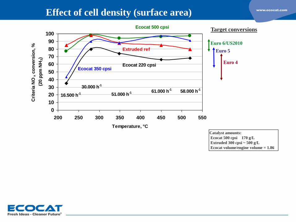
Extruded ref
Ecocat 500 cpsi
Ecocat 350 cpsiEcocat 220 cpsi
Effect of cell density (surface area)
Euro 6/US2010
Euro 5
Euro 4
Target conversions
Catalyst amounts:
Ecocat 500 cpsi 170 g/L
Extruded 300 cpsi ~ 500 g/L
Ecocat volume/engine volume = 1.86
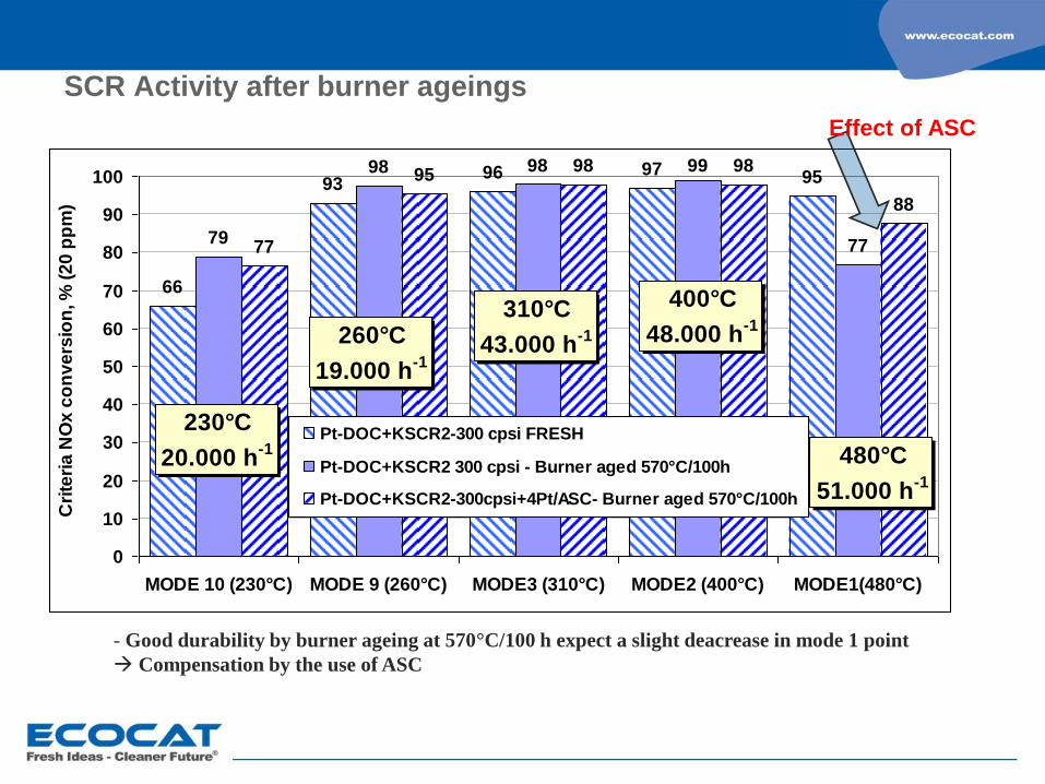
- Good durability by burner ageing at 570°C/100 h expect a slight deacrease in mode 1 point
Compensation by the use of ASC
SCR Activity after burner ageings
66
9396 97 95
79
98 98 99
7777
9598 98
88
0
10
20
30
40
50
60
70
80
90
100
MODE 10 (230°C) MODE 9 (260°C) MODE3 (310°C) MODE2 (400°C) MODE1(480°C)
Cri
teri
a N
Ox
co
nv
ers
ion
, %
(2
0 p
pm
)
Pt-DOC+KSCR2-300 cpsi FRESH
Pt-DOC+KSCR2 300 cpsi - Burner aged 570°C/100h
Pt-DOC+KSCR2-300cpsi+4Pt/ASC- Burner aged 570°C/100h
230°C
20.000 h-1
260°C
19.000 h-1
310°C
43.000 h-1
400°C
48.000 h-1
480°C
51.000 h-1
Effect of ASC
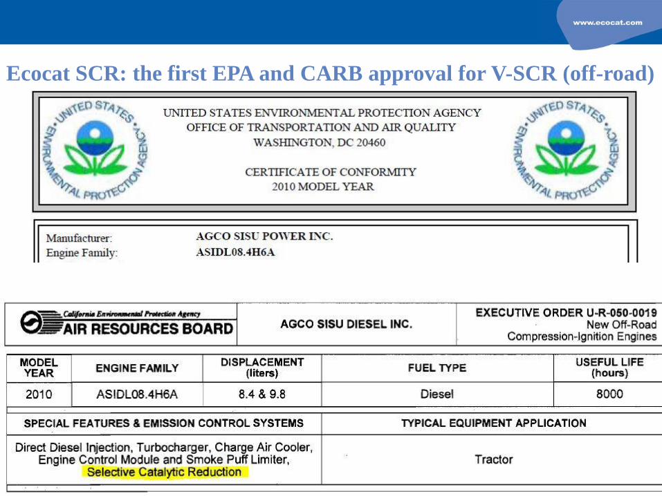
Ecocat SCR: the first EPA and CARB approval for V-SCR (off-road)
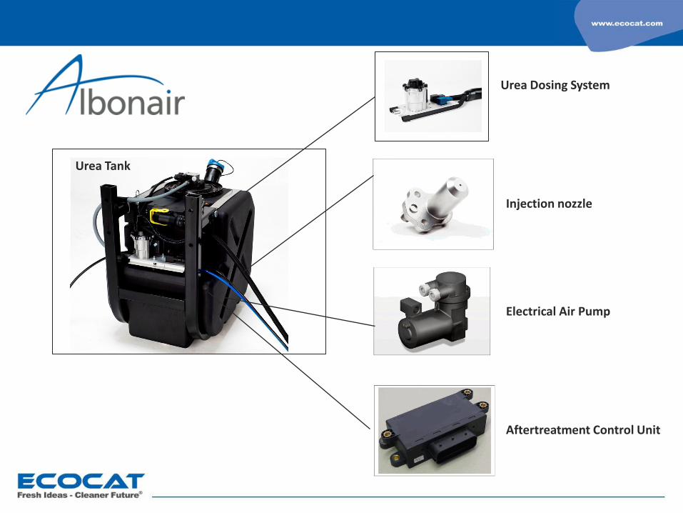
Urea Dosing System
Injection nozzle
Electrical Air Pump
Aftertreatment Control Unit
Urea Tank
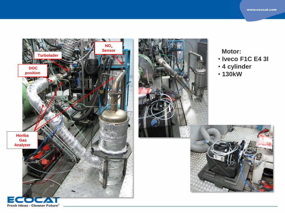
Motor:
• Iveco F1C E4 3l
• 4 cylinder
• 130kW
Turbolader
DOC
position
Horiba
Gas
Analyzer
NOx
Sensor

PM reduction technologies
coated DPF
POC-F (4th generation POC® )
active regeneration systems
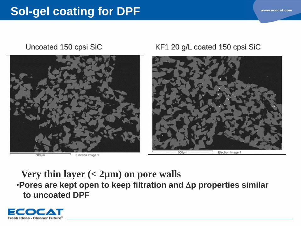
KF1 20 g/L coated 150 cpsi SiC Uncoated 150 cpsi SiC
Very thin layer (< 2µm) on pore walls •Pores are kept open to keep filtration and p properties similar
to uncoated DPF
Sol-gel coating for DPF

Poresize distribution of 200 cpsi SiC
Pore diameter (µm)
0
0,05
0,1
0,15
0,2
0,25
10 100
Po
re v
olu
me [
ml/g
]
SiC 200 uncoated SiC 200 KF1 60 g/L
21,5
21,8
Sol-gel coating for DPF

Coating on pores by sol-gel coating and process:
• Surface area of coating >200 m2/g as fresh
• Very thin layer (< 2µm) on pore walls
• Can be coated on e.g. SiC, ceramic and sintered metal filters
• Pt (or Pd) is added as active material on coating
Higher surface area for active component
Higher activity and stability
Sol-gel coating for DPF

Soot load Ecocat CDPFs vs. serial CDPF
0
2
4
6
8
10
12
14
16
18
20
0 500 1.000 1.500 2.000 2.500
distance [km]
so
ot
ma
ss
[g
]
soot load serial DPF
soot load Ecocat DPF 7556.1 [30g/ft³]
35 g/cft Pt
30 g/cft Pt
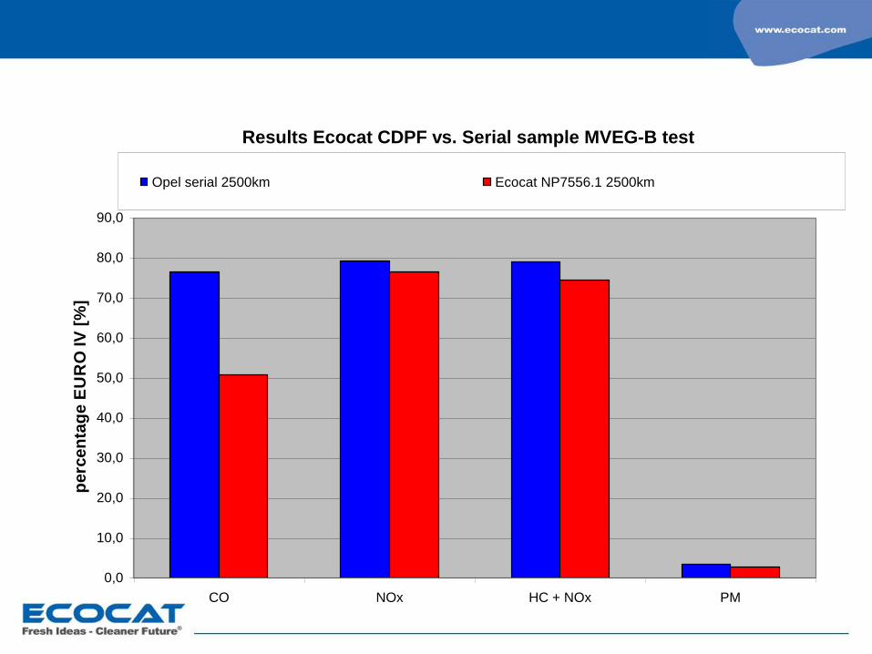
Results Ecocat CDPF vs. Serial sample MVEG-B test
0,0
10,0
20,0
30,0
40,0
50,0
60,0
70,0
80,0
90,0
CO NOx HC + NOx PM
perc
en
tag
e E
UR
O IV
[%
]
Opel serial 2500km (measured with winter tires) Ecocat NP7556.1 2500km (measured with winter tires)

POC-F
applicable for diesel Euro4/5 and GDI Euro6
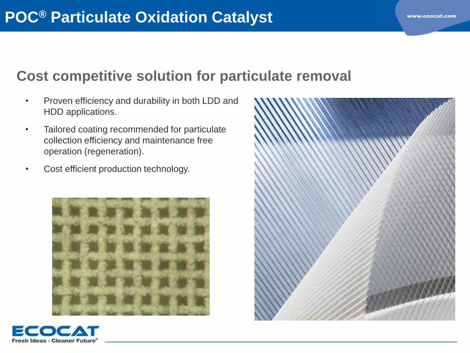
Cost competitive solution for particulate removal
• Proven efficiency and durability in both LDD and
HDD applications.
• Tailored coating recommended for particulate
collection efficiency and maintenance free
operation (regeneration).
• Cost efficient production technology.
POC® Particulate Oxidation Catalyst
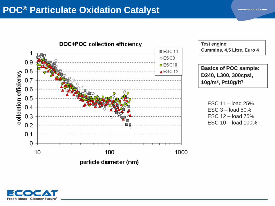
Test engine:
Cummins, 4,5 Litre, Euro 4
Basics of POC sample:
D240, L300, 300cpsi,
10g/m2, Pt10g/ft3
ESC 11 – load 25%
ESC 3 – load 50%
ESC 12 – load 75%
ESC 10 – load 100%
POC® Particulate Oxidation Catalyst
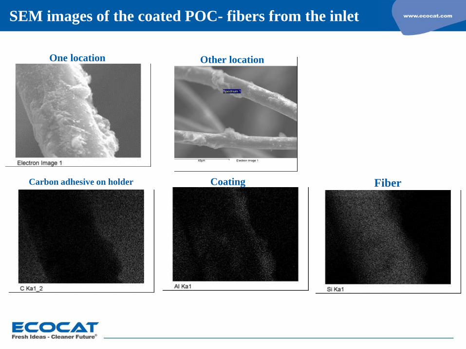
SEM images of the coated POC- fibers from the inlet
Coating Fiber Carbon adhesive on holder
Other location One location
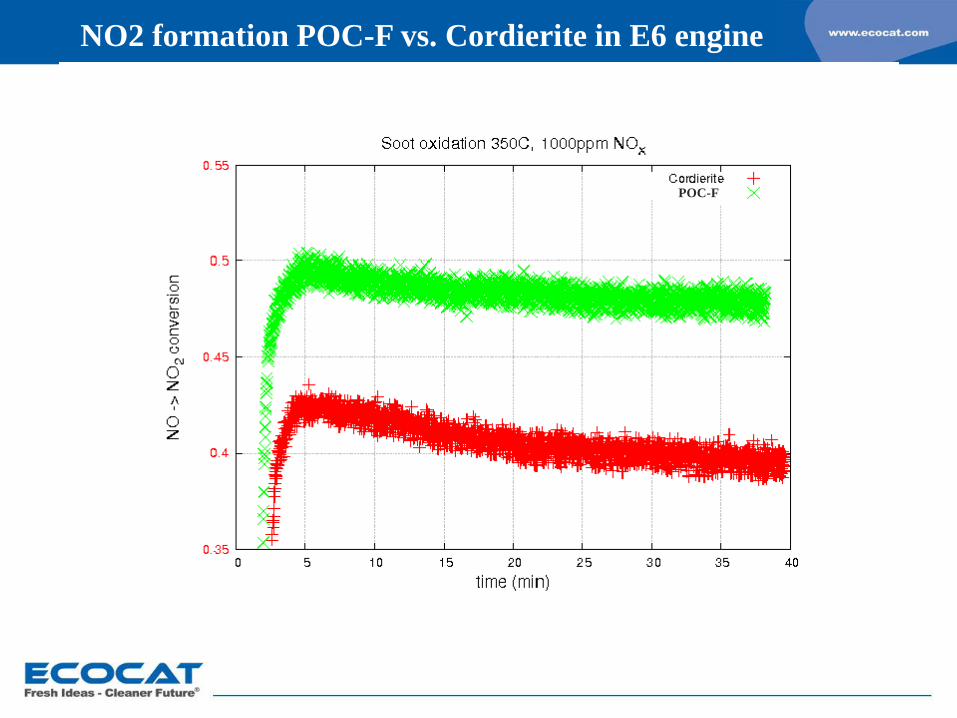
NO2 formation POC-F vs. Cordierite in E6 engine
POC-F
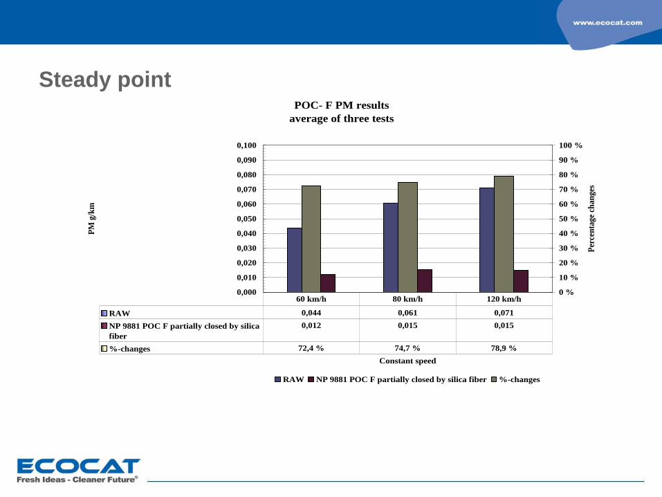
POC- F PM results
average of three tests
0,000
0,010
0,020
0,030
0,040
0,050
0,060
0,070
0,080
0,090
0,100
Constant speed
PM
g/k
m
0 %
10 %
20 %
30 %
40 %
50 %
60 %
70 %
80 %
90 %
100 %
Per
cen
tag
e ch
an
ges
RAW NP 9881 POC F partially closed by silica fiber %-changes
RAW 0,044 0,061 0,071
NP 9881 POC F partially closed by silica
fiber
0,012 0,015 0,015
%-changes 72,4 % 74,7 % 78,9 %
60 km/h 80 km/h 120 km/h
Steady point
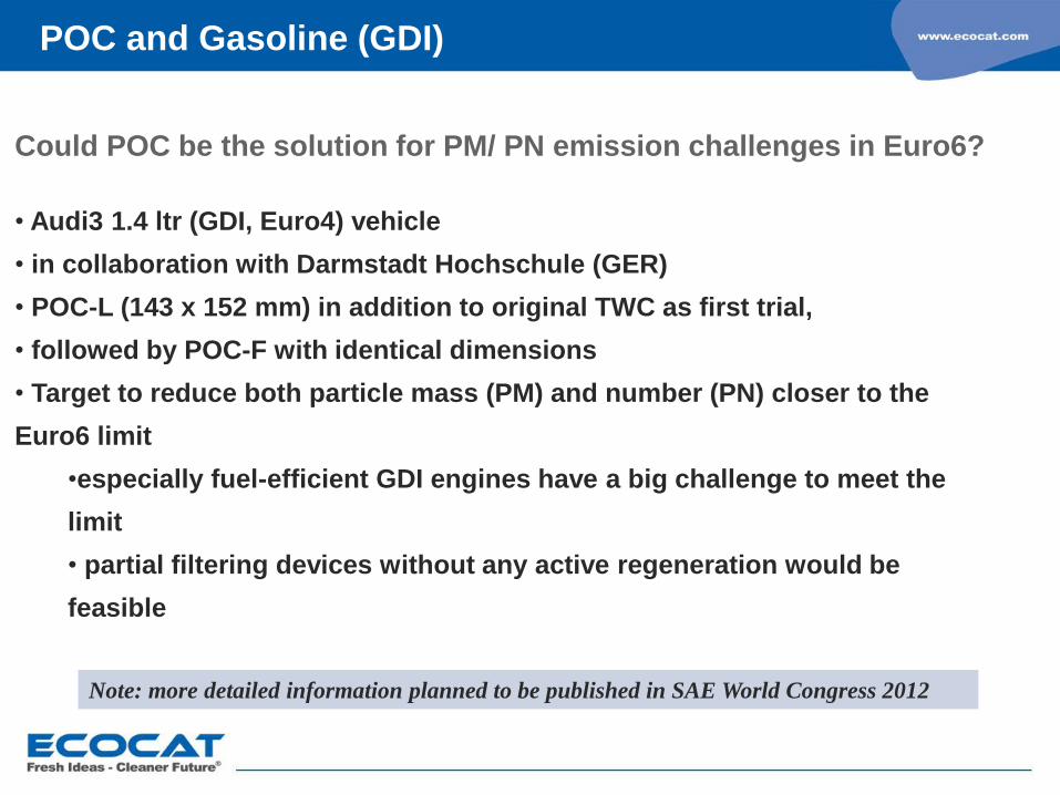
POC and Gasoline (GDI)
Could POC be the solution for PM/ PN emission challenges in Euro6?
• Audi3 1.4 ltr (GDI, Euro4) vehicle
• in collaboration with Darmstadt Hochschule (GER)
• POC-L (143 x 152 mm) in addition to original TWC as first trial,
• followed by POC-F with identical dimensions
• Target to reduce both particle mass (PM) and number (PN) closer to the
Euro6 limit
•especially fuel-efficient GDI engines have a big challenge to meet the
limit
• partial filtering devices without any active regeneration would be
feasible
Note: more detailed information planned to be published in SAE World Congress 2012
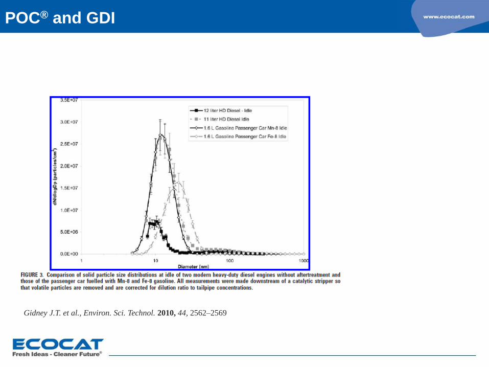
Gidney J.T. et al., Environ. Sci. Technol. 2010, 44, 2562–2569
POC® and GDI
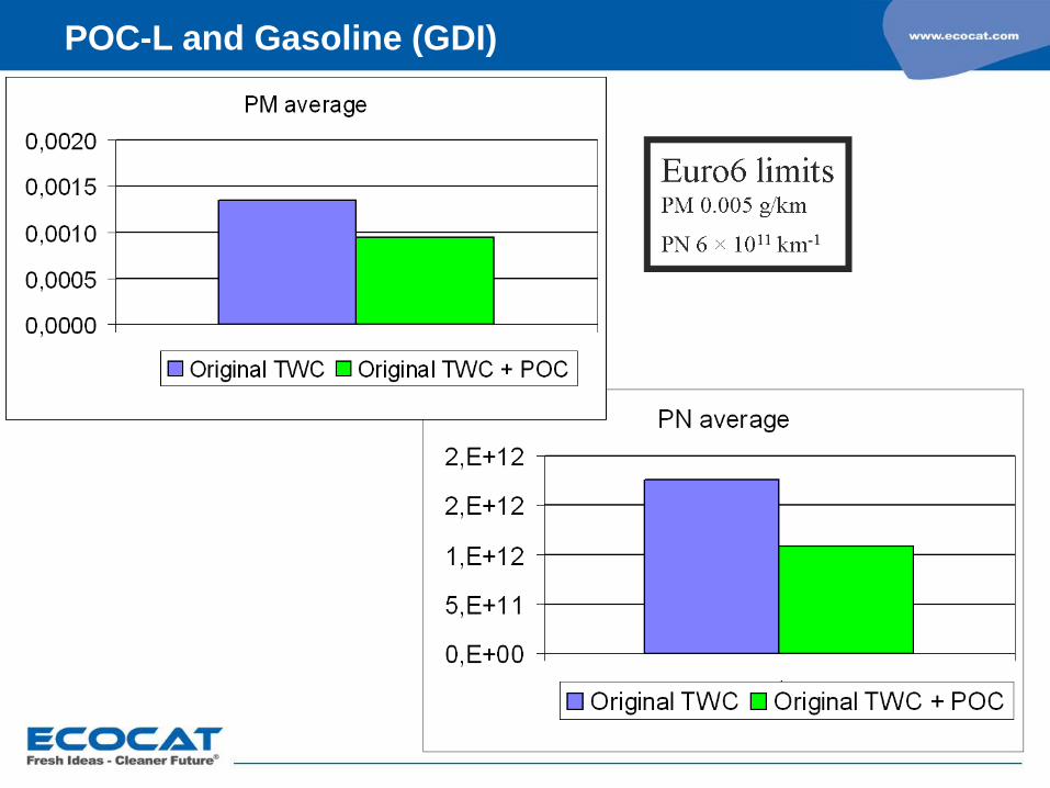
POC-L and Gasoline (GDI)
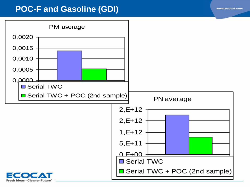
POC-F and Gasoline (GDI)
PN average
0,E+00
5,E+11
1,E+12
2,E+12
2,E+12
1Serial TWC
Serial TWC + POC (2nd sample)
PM average
0,0000
0,0005
0,0010
0,0015
0,0020
1Serial TWC
Serial TWC + POC (2nd sample)
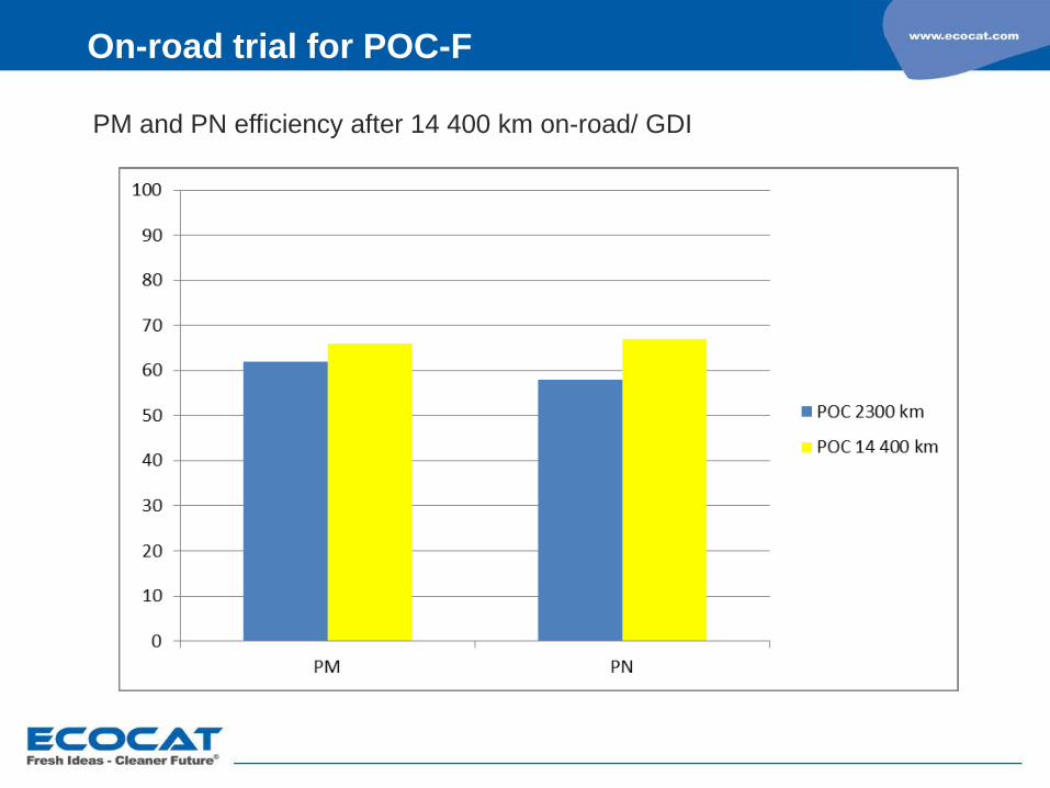
On-road trial for POC-F
PM and PN efficiency after 14 400 km on-road/ GDI
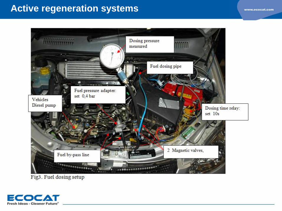
Active regeneration systems

Alternative fuels
- case CNG and LPG -
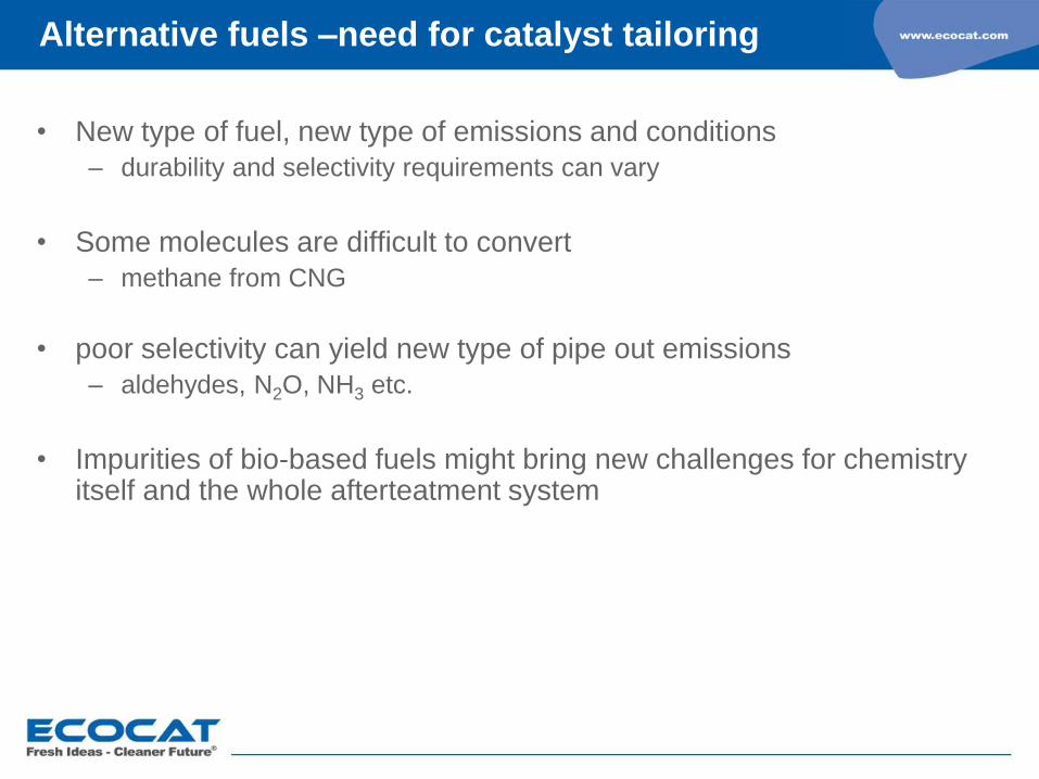
Alternative fuels –need for catalyst tailoring
• New type of fuel, new type of emissions and conditions
– durability and selectivity requirements can vary
• Some molecules are difficult to convert
– methane from CNG
• poor selectivity can yield new type of pipe out emissions
– aldehydes, N2O, NH3 etc.
• Impurities of bio-based fuels might bring new challenges for chemistry itself and the whole afterteatment system

Alternative fuels –need for catalyst tailoring
• PGM loadings and ratios (Pt-Pd-Rh)
• Interaction with active sites and carrier
– Stabilizing, promoting
• Adsorption properties and selectivity tuning by varying the composition
• Different layers
• Zone coating

Advantages
• Lower CO2 emissions compared to gasoline and diesel
• No particulate emissions!
• Significantly lower NOx emissions
• Other benefits
Global natural gas sources
Lower noise level
Odourless exhaust gas
Disandvantages
• In heavy duty, need for engine development
• Methane emissions specific CNG catalysts is needed
Natural gas –potential solution
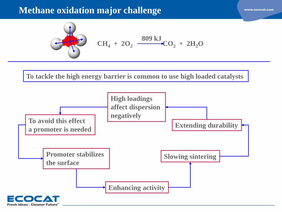
CH4 + 2O2 CO2 + 2H2O 809 kJ
High loadings
affect dispersion
negatively To avoid this effect
a promoter is needed
Promoter stabilizes
the surface
Enhancing activity
To tackle the high energy barrier is common to use high loaded catalysts
Slowing sintering
Extending durability
Methane oxidation major challenge
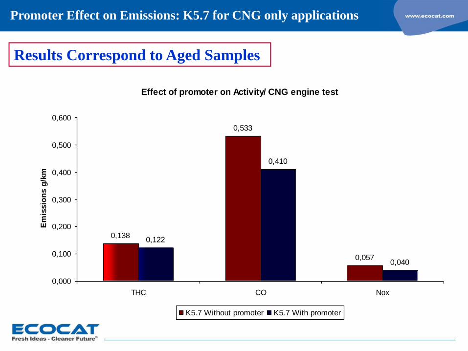
Effect of promoter on Activity/ CNG engine test
0,138
0,533
0,057
0,122
0,410
0,040
0,000
0,100
0,200
0,300
0,400
0,500
0,600
THC CO Nox
Em
issio
ns g
/km
K5.7 Without promoter K5.7 With promoter
Promoter Effect on Emissions: K5.7 for CNG only applications
Results Correspond to Aged Samples

engine optimisation with our K5.7, enhancing CH4 conversion
• Ideal operation point is correlated to temperature and lambda
• Sligthly rich operation under transient conditions improves CH4 conversion
Advantages
• Lower CO2 emissions compared to gasoline
• Significantly lower PM and NOx emissions than diesel
• Easy logistics, resources and distribution
• Safety issues vs. CNG
• Catalysts are typically low-loaded, optimized TWC catalysts
Disandvantages
• Low power output from powertrain
• Performance under cold conditions
LPG – growing fast

Summary
V-SCR technology is durable, robust and shown to be a feasible solution
also by EPA/ CARB
SCR catalysts combined with PreOxicat, PostOxicat, hydrolysis catalyst
or/and catalyzed particulate filters can be designed by the application
On DPF uniform coating through the wall provides good stability
Active regeneration needed when driving conditions do not ensure
passive systems (POC-F and DPF)
Alternative fuels and new engine technologies are coming, catalyst
tailoring is needed
Thank You for Your Attention!