Embed Size (px)
Citation preview
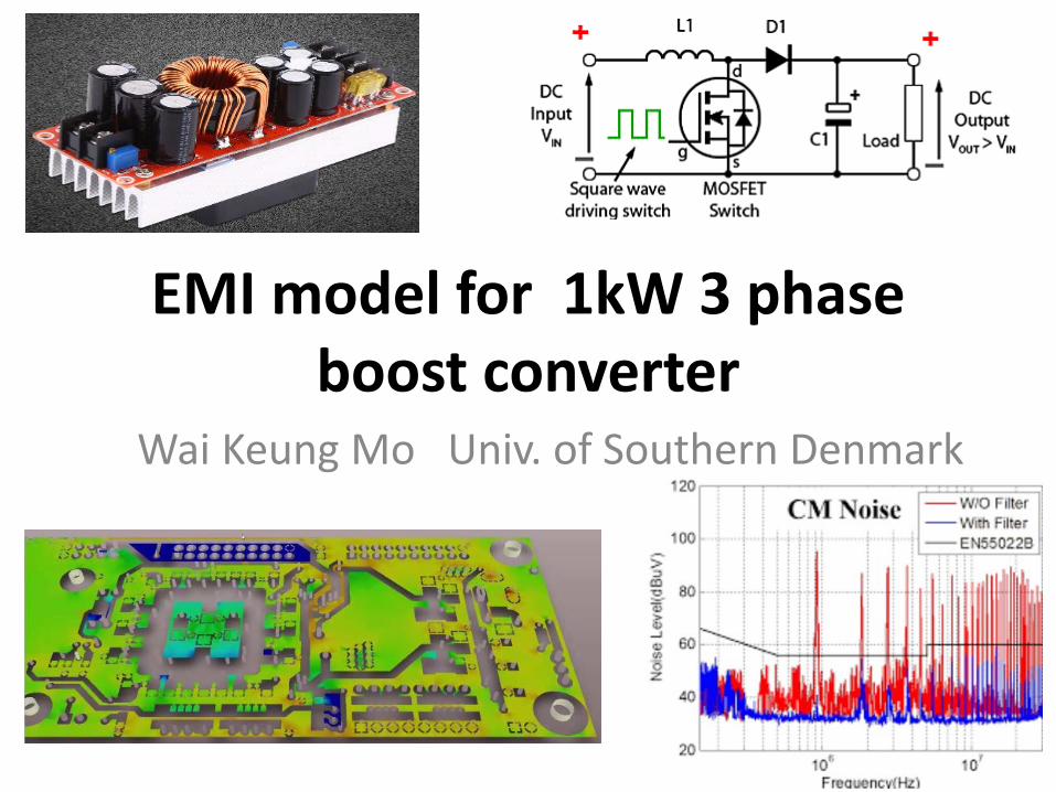
EMI model for 1kW 3 phase boost converter
Wai Keung Mo Univ. of Southern Denmark

Acknowledgments
This project was funded as part of the PET-PhDproject, involving the companies Danfoss A/S, Lodam A/S and Force Technology ( Delta).We are grateful for their technical assistance in terms of inspiring discussions and equipmentsupports.The project was funded by Region Syddanmark.
Background of PET-PhD subproject
This project was started at the beginning of2015 and finished at the end of 2017.The major target of this subproject was toinvestigate a ”Model Based Design” approach topredict EMI noise emission and optimize RFIfilter for DC to DC converter.
Agenda
• Introduction• A preventive approach for EMI issue• Methodology• EMI model of 1kW 3 phase boost converter• Experimental and simulation results• Result comparison between EMI experiment
and simulation• Conclusions

EMC in design progress
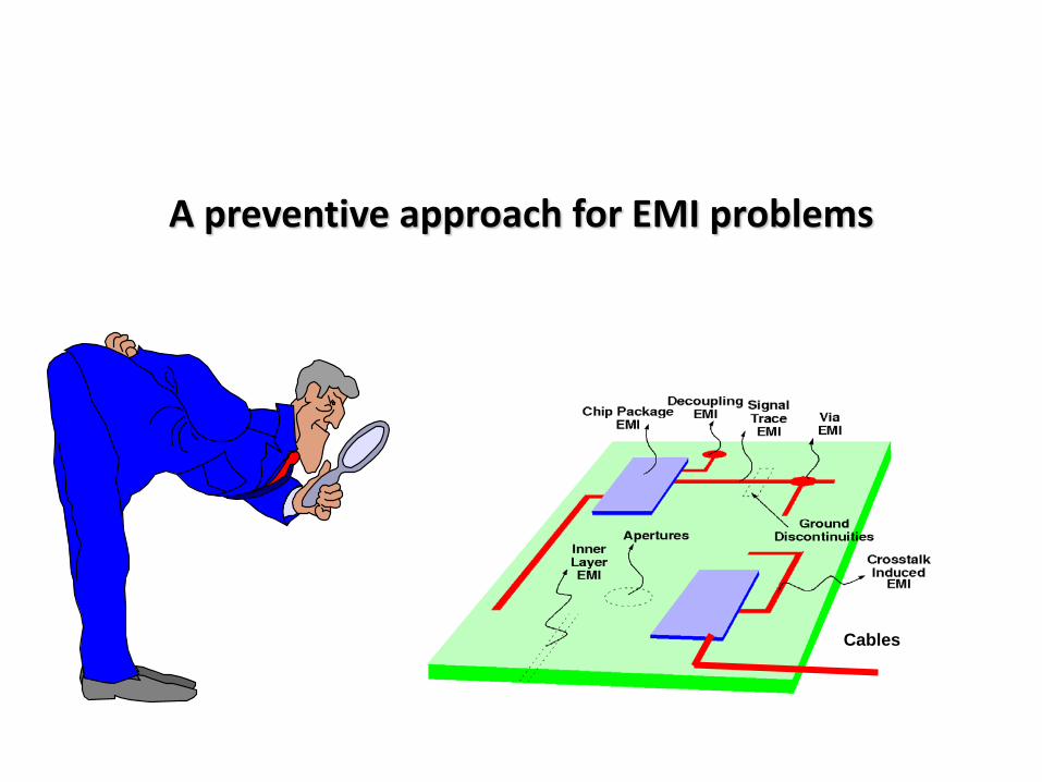
A preventive approach for EMI problems
Cables

Methodology
A preventive approach for EMI problems
24 hrs EMC consultant = Appropriate EMI simulation
ANSYS

Complete conducted EMI simulation solution
Simplorer
Maxwell
Q3DConducted EMI solution
Electrical circuit modelling, simulating and analyzing virtual system prototype as well as co-simulation with Q3D and Maxwell
Modelling and Simulation non-linear magnetic devices under transient analysis
PCB layout modelling and simulating as well as converting into spice model

EMI model of 1kW 3 phase boost converter
EMI solution = EMI simulation modelling
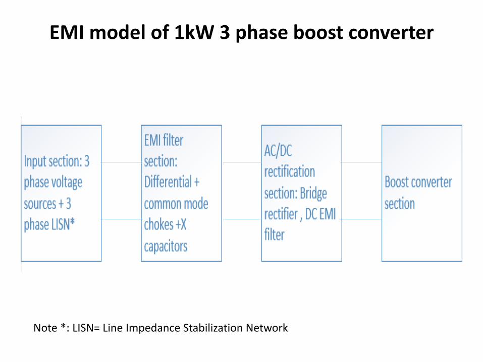
EMI model of 1kW 3 phase boost converter
Note *: LISN= Line Impedance Stabilization Network
*

Input section

EMI filter section
N=40, Core material=MS105125-2
𝑁𝑁𝐿𝐿𝐿=𝑁𝑁𝐿𝐿2=𝑁𝑁𝐿𝐿3=𝑁𝑁𝑁𝑁𝐿=14, Core material=N87

AC/DC rectification section
L5: (N=72, MS-1570125-2)L6=L7:(N=75, T184-26)

Boost converter section

Experimental and simulation results
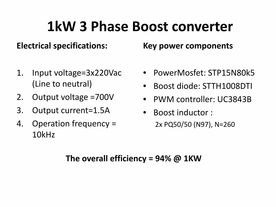
1kW 3 Phase Boost converterElectrical specifications:
1. Input voltage=3x220Vac (Line to neutral)
2. Output voltage =700V3. Output current=1.5A4. Operation frequency =
10kHz
Key power components
• PowerMosfet: STP15N80k5• Boost diode: STTH1008DTI• PWM controller: UC3843B• Boost inductor :
2x PQ50/50 (N97), N=260
The overall efficiency = 94% @ 1KW

Experimental results(transistor switching waveforms)
Voltage waveform across Vds of power mosfet
Current waveform
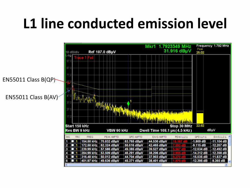
L1 line conducted emission level
EN55011 Class B(QP)
EN55011 Class B(AV)

L2 line conducted emission level
EN55011 Class B(QP)
EN55011 Class B(AV)

L3 line conducted emission level
EN55011 Class B(QP)
EN55011 Class B(AV)

Simulation results
Simulation conditions:• Vo=697V• Io=1.529A• Switching frequency=10kHz• Vin=220Vrms (line to neutral)

L1 line conducted noise level(Peak emission)

L2 line conducted noise level(Peak emission)
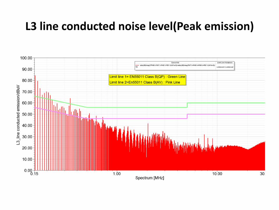
L3 line conducted noise level(Peak emission)

Result comparison between EMI experiment and simulation

Result comparison between EMI measurement and simulation
(L1 conducted emission level, Vin=220Vac, Vo=697.4V,Io=1.529A)
0
10
20
30
40
50
60
70
80
90
100 1000 10000
L1_l
ine
cond
ucte
d em
issi
on le
vel /
dBuV
f/kHz
L1(peak emission)
L1(simulation result)

Result comparison between EMI measurement and simulation
(L2 conducted emission level, Vin=220Vac, Vo=697.4V,Io=1.529A)
0
10
20
30
40
50
60
70
100 1000 10000
L2_l
ine
cond
ucte
d em
issi
on le
vel/
dBuV
f/kHz
L2(peak emission)L2(simulation result)

Result comparison between EMI measurement and simulation (L3 conducted emission level, Vin=220Vac, Vo=697.4V,Io=1.529A)
0
10
20
30
40
50
60
70
80
90
100 1000 10000
L3_l
ine
cond
ucte
d em
issi
on le
vel/
dBuV
f/kHz
L3(peak emission)
L3(simulation result)

Project challenges IQ3D is the best tool to extract all the parasitic components (RLCG) with given physicaldimensions such as PCB and BNC cables; however it is challenging to solve the non-linear magnetic device effectively. For example, the permeability of magnetic materialshould be a constant.

Project challenges IIMaxwell is a good tool to solve all the non-linear magnetic devices such as filterinductor or transformer with self-definition of magnetic characteristics such as BHcurves. Also, it can perform transient analysis with given current or voltage waveformsas excitation sources; however it consumes huge computer sources for co-simulationwith simplorer (2 weeks on a 4 GHz PC….).

The solution of magnetic device model
The effective magnetic device model was done by the equivalent electrical circuit model withmerging of all the solutions by Q3D and Maxwell. For example, all the parasitic capacitances werebe done by Q3D and all the parasitic inductances and ac winding resistances were be done byMaxwell.
=f(i)
Q3Dsolution
Maxwellsolution
Conclusions
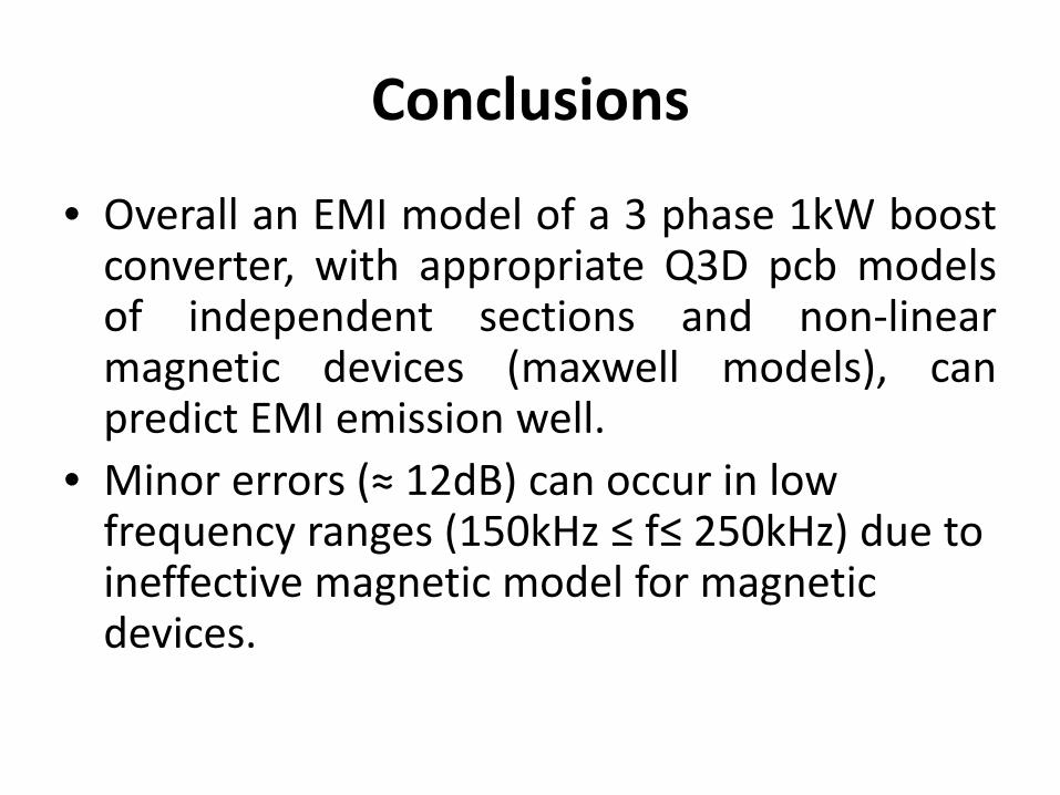
• Overall an EMI model of a 3 phase 1kW boostconverter, with appropriate Q3D pcb modelsof independent sections and non-linearmagnetic devices (maxwell models), canpredict EMI emission well.
• Minor errors (≈ 12dB) can occur in low frequency ranges (150kHz ≤ f≤ 250kHz) due to ineffective magnetic model for magneticdevices.


![MODELLING AND SIMULATING THE DYNAMICS OF …Horvat, Wydra, Lerch: Modelling and Simulating the Dynamics of the European Demand … 421 flows [22]. The SD approach is suitable for researching](https://img.dokumen.tips/doc/110x75/5ecb651e7ea26225da08c64c/modelling-and-simulating-the-dynamics-of-horvat-wydra-lerch-modelling-and-simulating.jpg)