Embed Size (px)
Citation preview

EMF Fundamentals
Page 1 of 9 European EMC Products Ltd
European EMC Products Limited Unit 8 : Saffron Business Centre : Elizabeth Way : Saffron Walden : Essex : CB10 2NL
Tel + 44 1799 523073 : Fax + 44 1799 521191 Email : [email protected] : Web : http://www.euro-emc.co.uk
Table of Contents
Electric Charge, Current & Voltage
Electric & Magnetic Fields
Magnetic Flux Density and Conversion Factors
ELF EMF, 50 and 60-Hz Wavelength, DC & AC Fields
Electrostatic and Electromagnetic Induction
Loop Magnetic Field Sources
Single Conductor Magnetic Field Sources
Dual Conductor Magnetic Field Sources
Three-Phase Magnetic Field Sources
Ground, Plumbing & Net Currents
Video Display Units (VDU’s)
Magnetic Field Mitigation
Rigid Magnetic Shielding

EMF Fundamentals
Page 2 of 9 European EMC Products Ltd
European EMC Products Limited Unit 8 : Saffron Business Centre : Elizabeth Way : Saffron Walden : Essex : CB10 2NL
Tel + 44 1799 523073 : Fax + 44 1799 521191 Email : [email protected] : Web : http://www.euro-emc.co.uk
Electric Charge, Current & Voltage
Electric charge, whether negative electrons or positive protons, is measured in units called coulombs (C), where one coulomb has the charge of 6 x 10E+18 electrons or protons. Electric charges exist both in free space (thunder storms) and on conductive materials (wires, metal, glass, rugs, water, etc.). When an electric charge is in motion it is called current, which is measured in amperes (A). One ampere is equal to one coulomb of electric charge per second past a defined reference point. The electric potential between two points, defined as voltage (V), is the work measured in joules per coulomb (or voltage) necessary to move a unit electric charge between the two points.
Electric & Magnetic Fields
Electric fields E, a vector quantity measured in volts per meter (V/m), are created by electric charges in free space and on conductive objects. Electric fields emanate out and down toward the ground diminishing in magnitude (field strength) at a linear 1/r rate from line sources (unshielded transmission lines, etc.) and at a non-linear 1/r² distance rate from point sources (appliances). Near extra-high voltage (EHV) transmission lines, defined as between 230-765 kilovolts (kV), one can hear the corona (crackle) produced by ionising air molecules and sense the presence (tingle) of electric fields on the hair and skin. Under the midspan of a 230 kV and 500 kV transmission line, the electric field strength is 2 kV/m and 7 kV/m, respectively, one metre above the ground; more than enough to illuminate a hand-held fluorescent tube. Fortunately, grounded conductive objects including trees, bushes, buildings, and metal conduits easily attenuate (reduce) or completely shield electric fields. Therefore, properly grounded metal conduits and equipment cases do not emanate electric fields.
Magnetic fields H, a vector quantity measured as amperes per meter (A/m) in the MKS system and oersted (Oe) in the CGS system, are generated when electric charges are moving in free space and within conductors. High current sources such as lightning, transmission and distribution lines, transformers, network protectors, secondary feeders, switchgears, distribution busbars, electrical panels, motors, and electric heaters produce very high magnetic fields. Unfortunately, magnetic fields are extremely difficult to shield and easily permeate (penetrate) nearly all materials including people, trees, buildings, equipment, and most metals except special ferromagnetic and highly conductive (copper and aluminium) materials. Normally, people are not able to sense the presence of very high 10-1,000 mG magnetic fields; however, extremely high levels exceeding 100 Gauss (100,000 mG) will cause a temporary visual flickering sensation called magnetophosphenes which disappears when the field is removed.

EMF Fundamentals
Page 3 of 10 European EMC Products Ltd
European EMC Products Limited Unit 8 : Saffron Business Centre : Elizabeth Way : Saffron Walden : Essex : CB10 2NL
Tel + 44 1799 523073 : Fax + 44 1799 521191 Email : [email protected] : Web : http://www.euro-emc.co.uk
Magnetic Flux Density and Conversion Factors
When an emanating magnetic field H permeates through a cross-sectional area of a medium (vacuum, free space or material), it converts to magnetic flux density B according to the following formula:
B magnetic flux density = µH magnetic field where µ is the permeability of the medium The permeability of a vacuum designated as µo and free space (air) are nearly identical: 4 x 10E-7 henry per meter (H/m) in MKS units and 1-gauss/oersted in CGS units. Magnetic flux density B is defined in MKS units as tesla (T) and in CGS units as gauss (G). It should be noted that in the United States CGS units oersted (Oe), gauss (G), and milligauss (mG) are the normal convention in power engineering and electromagnetics rather than the MKS units, except in scientific journals. Also, when working in free space both gauss (G) and oersted (Oe) are equal in magnitude as shown:
B gauss = µoH oersted where µo = 1-gauss/oersted. For example, a 0.020 oersted magnetic field H in free space is equal to a magnetic flux density B of .020 gauss (20 mG). Although not technically accurate, the terms magnetic field H and magnet ic flux density B usually appear synonymous in the engineering literature. Magnetic flux density B is measured with a gaussmeter in milligauss (mG) and easily converted to magnetic field H in either CGS and MK S units with the handy conversion factors listed below:
ELF EMF, 50 and 60-Hz Wavelength, DC & AC Fields
Electric power generated in United Kingdom is 50-Hz and in North America 60-Hz alternating current (AC). This means both the voltage and current are sinusoidally varying (change polarity twice in each cycle or 100 or 120 times every second). A 60-Hz AC line frequency has an extremely long wavelength of 3,100 miles (5,000 km) calculated between cycles using:
C speed-of-light = ( wavelength)(frequency). Alternating current (AC) electric and magnetic fields fluctuate in space as the sinusoidally varying voltage and current change polarity, whereas DC fields (like the earth's geomagnetic field) remain statically polarized based upon the direction of the current flow (remember the Right Hand Rule). Incidentally, the geomagnetic (static) field is typically 670 mG at the magnetic poles, 500 mG around the middle latitudes, and 330 mG on the equator. Furthermore, when the distance from a sinusoidally varying source such as a 50 or 60-Hz AC power is small with respect to the wavelength (known as the near field), the electric and magnetic fields are not coupled and considered separate physical entities. That is why 60-Hz electric fields can be grounded to zero inside a metal conduit;
EMF Fundamentals
Page 4 of 10 European EMC Products Ltd
European EMC Products Limited Unit 8 : Saffron Business Centre : Elizabeth Way : Saffron Walden : Essex : CB10 2NL
Tel + 44 1799 523073 : Fax + 44 1799 521191 Email : [email protected] : Web : http://www.euro-emc.co.uk
however, the unperturbed magnetic fields will still emanate through the conduit. The opposite is true for radio frequency sources that have significantly shorter wavelengths and radiate coupled electric and magnetic fields into free space several wavelengths from the antenna (known as the far field).
Electrostatic and Electromagnetic Induction
Electrostatic induction occurs when alternating 50 or 60-Hz electric fields couple with conductive animate (humans) and inanimate objects, thereby inducing currents and voltages within the objects. The actual current consists of minute movements of charged particles: electrons in metallic conductors and ionic conduction in body tissues and fluids. The voltages and currents induced directly into humans are of concern if they are high enough to cause direct biological, physiological, and psychological effects.
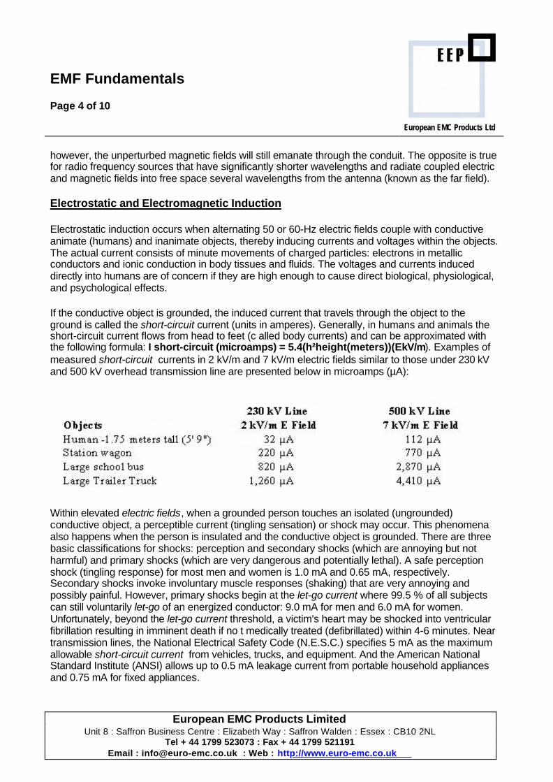
If the conductive object is grounded, the induced current that travels through the object to the ground is called the short-circuit current (units in amperes). Generally, in humans and animals the short-circuit current flows from head to feet (c alled body currents) and can be approximated with the following formula: I short-circuit (microamps) = 5.4(h²height(meters))(EkV/m). Examples of measured short-circuit currents in 2 kV/m and 7 kV/m electric fields similar to those under 230 kV and 500 kV overhead transmission line are presented below in microamps (µA):
Within elevated electric fields, when a grounded person touches an isolated (ungrounded) conductive object, a perceptible current (tingling sensation) or shock may occur. This phenomena also happens when the person is insulated and the conductive object is grounded. There are three basic classifications for shocks: perception and secondary shocks (which are annoying but not harmful) and primary shocks (which are very dangerous and potentially lethal). A safe perception shock (tingling response) for most men and women is 1.0 mA and 0.65 mA, respectively. Secondary shocks invoke involuntary muscle responses (shaking) that are very annoying and possibly painful. However, primary shocks begin at the let-go current where 99.5 % of all subjects can still voluntarily let-go of an energized conductor: 9.0 mA for men and 6.0 mA for women. Unfortunately, beyond the let-go current threshold, a victim's heart may be shocked into ventricular fibrillation resulting in imminent death if no t medically treated (defibrillated) within 4-6 minutes. Near transmission lines, the National Electrical Safety Code (N.E.S.C.) specifies 5 mA as the maximum allowable short-circuit current from vehicles, trucks, and equipment. And the American National Standard Institute (ANSI) allows up to 0.5 mA leakage current from portable household appliances and 0.75 mA for fixed appliances.
EMF Fundamentals
Page 5 of 10 European EMC Products Ltd
European EMC Products Limited Unit 8 : Saffron Business Centre : Elizabeth Way : Saffron Walden : Essex : CB10 2NL
Tel + 44 1799 523073 : Fax + 44 1799 521191 Email : [email protected] : Web : http://www.euro-emc.co.uk
Electromagnetic induction occurs when alternating 50 or 60-Hz magnetic fields couple with animate (humans) and inanimate conductive objects (wires, metal beams, HVAC ducts, etc.), thereby inducing circulating currents and voltages. Magnetically induce d body currents in human tissues flow primarily in peripheral loops (called eddy currents) perpendicular to the field; however, current at the centre is generally near zero. Magnetic fields from transmission lines will normally induce voltages at the open ends of long, partially grounded, parallel conductors (fences, wires, and exposed pipes). So, dangerous and potentially lethal shocks from electromagnetic induction are also a serious problem.
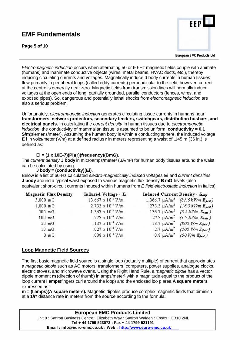
Unfortunately, electromagnetic induction generates circulating tissue currents in humans near transformers, network protectors, secondary feeders, switchgears, distribution busbars, and electrical panels. In calculating the current density in human tissues due to electromagnetic induction, the conductivity of mammalian tissue is assumed to be uniform: conductivity = 0.1 S/m(siemens/meter). Assuming the human body is within a conducting sphere, the induced voltage E i in volts/meter (V/m) at a defined radius r in meters representing a waist of .145 m (36 in.) is defined as:
Ei = (1 x 10E-7)(PI)(r)(frequency)(BmG). The current density J body in microamps/meter² (µA/m²) for human body tissues around the waist can be calculated by using:
J body = (conductivity)(Ei). Below is a list of 60-Hz calculated electro-magnetically induced voltages Ei and current densities J body around a typical waist exposed to various magnetic flux density B mG levels (also equivalent short-circuit currents induced within humans from E field electrostatic induction in italics):
Loop Magnetic Field Sources
The first basic magnetic field source is a single loop (actually multiple) of current that approximates a magnetic dipole such as AC motors, transformers, computers, power supplies, analogue clocks, electric stoves, and microwave ovens. Using the Right Hand Rule, a magnetic dipole has a vector dipole moment m (direction of thumb) in amps/meter² with a magnitude equal to the product of the loop current I amps(fingers curl around the loop) and the enclosed loo p area A square meters expressed as: m = (I amps)(A square meters). Magnetic dipoles produce complex magnetic fields that diminish at a 1/r³ distance rate in meters from the source according to the formula:
EMF Fundamentals
Page 6 of 10 European EMC Products Ltd
European EMC Products Limited Unit 8 : Saffron Business Centre : Elizabeth Way : Saffron Walden : Essex : CB10 2NL
Tel + 44 1799 523073 : Fax + 44 1799 521191 Email : [email protected] : Web : http://www.euro-emc.co.uk
B mG = 2(I amps)(A sq.meters)/r³meters. For example, the magnetic fields from a distribution transformer can be calculated by using the secondary per phase current I amps and a scaling factor of 1-mG· m³/A for A sq.meters in the above formula.
Single Conductor Magnetic Field Sources
The second basic magnetic field source is a straight, single conductor of current that is represented by the formula:
B mG = 2(I amps)/r meter. It also applies to ground, plumbing and net currents plus electrically powered subway, rail, and trolley-bus systems with either an overhead electrified cable (pantograph) or third-rail. The magnetic fields from a single conductor are circular emanating out from the centre and impossible to magnetically shield (with a conduit or enclosure) using any material including highly permeable mumetals (flux-entrapment) or highly conductive copper and aluminium (eddy-current) materials ( see EMF Fundamentals - Rigid Magnetic Shielding). Fortunately, passive and active magnetic field cancellation technology will mitigate single conductor and net, ground, and plumbing current magnetic fields.
Dual Conductor Magnetic Field Sources
The magnetic field for an opposing current pair of dual conductors (single phase pair, electrical appliance cord, knob-and-tube wiring, etc.) separated by a small distance d meter between the conductors relative to the distance from the pair r meters diminishes at a non-linear 1/r²distance rate according to the formula:
B mG = 2(I amps)(d meters)/r²meters. This is the famous inverse square law that also applies to radiating radio frequency (RF) EMF, electric fields, light, sound, and of course gravity. Basically, by doubling the distance r meter for a fixed spacing d meter and current load I amps, the magnetic flux density reduces by a factor of four (4). For example, the magnetic flux density B mG levels at 1, 2 & 4-inches (r = .025 m, .05 m & .1 m) from a typical electrical cord (spacing d=.001 m) with a 10 amp load are 32 mG, 8 mG, and 2 mG, respectively.
Three-Phase Magnetic Field Sources
Electric power in most countries is generated and distributed via three-phase AC transmission, distribution, and service feeder lines to commercial, institutional, and industrial buildings. Each of the three balanced phase voltages and currents are ideally represented as phases (magnitude and angle) 120 degrees apart. The magnetic field for balanced three-phase circuits of three horizontally or vertically arrayed conductors separated by equal distances d meter diminishes at a non-linear 1/r²distance rate according to:
B mG = 3.46(I amps)(d meters)/r²meters.

EMF Fundamentals
Page 7 of 10 European EMC Products Ltd
European EMC Products Limited Unit 8 : Saffron Business Centre : Elizabeth Way : Saffron Walden : Essex : CB10 2NL
Tel + 44 1799 523073 : Fax + 44 1799 521191 Email : [email protected] : Web : http://www.euro-emc.co.uk
However, if the three-phase circuit is unbalanced and/or there are significant net, ground, and plumbing currents on the service feeder neutral (see next section for more details), then the dominant magnetic field becomes:
B mG = 2(I amps)/r meter, where I amps is the sum of the net, ground, and plumbing currents. Finally, magnetic fields produced by three phase lines are generally elliptically polarized. This means the magnetic field can be represented by a rotating vector that traces an ellipse for every cycle of the conductor currents.
Ground, Plumbing & Net Currents
Ground currents are a collective term for any errant electrical currents measured in amperes (A) that result from the natural grounding process to earth including currents on conduits, ground wires, ground rods, building steel, metal HVAC ducts, and metal water pipes (also known as plumbing currents). These ground currents normally generate magnetic fields that emanate out from a grounding conductor (ground wire, water pipe, metal HVAC duct, etc.) at a diminishing linear 1/rdistance rate according to the formula:
B mG = 2(I amps)/r meters. Both ground currents and plumbing currents can be easily calculated by recording the magnetic flux density at a measured distance r feet from the source:
I amps = .15(B mG)(r feet). However, it is much easier to use a clamp-on amp meter around a grounding conductor or water pipe (if practical) for an accurate measurement.
Net currents, also known as unbalanced or zero-sequence currents, are the vector sum of all the phase (conductor) currents. In perfectly balanced, single-circuit, three-phase transmission and distribution lines, the net current is zero wh en all three phase currents are equal. Theoretically, if a clamp-on amp meter could be safely placed around the three phase conductors it would measure zero amps -- indicating no net current. However, if phases A and B were 1000 amps and phase C 1500 amps , there would be a measurable net current. This net current produces a magnetic field that also diminishes at a linear 1/rdistance rate like a ground or plumbing current according to:
B mG = 2(I amps)/r meters. For example, a 500 amp net, ground or plumbing current produces a 1,000 mG field at 1 meter (3.3 ft.), 500 mG at 2 meters (6.6 ft.), 250 mG at 4 meters (13.2 ft.), 200 mG at 5 meters (16.5 ft.),100 mG at 10 meters (33 ft.), and finally a 3 m G at 333.3 meters (1094 ft.).
In commercial buildings, neutral net currents are very problematic in four-wire three-phase service feeders (480V/277V and 208V/120V). Ideally, when the three phases are unbalanced and there are absolutely no neutral return currents from harmonic and transient sources (reactive loads such as motors, computers, dimmers, heavy machinery, etc.) and/or errant ground/plumbing currents, the unbalanced return neutral current effectively cancels out the unbalanced phase current resulting in zero net current: if and only if the four conductors are bundled close together within the same conduit or busbar. Typically, there are complex harmonic and transient components on the return neutral that generate noisy net currents . Frequently, externally produced ground and

EMF Fundamentals
Page 8 of 10 European EMC Products Ltd
European EMC Products Limited Unit 8 : Saffron Business Centre : Elizabeth Way : Saffron Walden : Essex : CB10 2NL
Tel + 44 1799 523073 : Fax + 44 1799 521191 Email : [email protected] : Web : http://www.euro-emc.co.uk
plumbing currents from nearby electrical sources leak into the return neutral via the neutral-ground bond in the switchgear and migrate back to the multiground neutral (MGN) system. The cumulative magnetic field that emanates from neutral net, ground, and plumbing currents on service feeders presents a very serious EMI threat to nearby sensitive electronic equipment and occupants.
Video Display Units (VDU’s)
Since 1990 most video display units (VDU) manufacturers have voluntarily complied with the Swedish MPR2 and recent IEEE P1140 electric and magnetic field VDT emission standards. Levels are measured 50 cm (20 inches) from the monitor for two specific frequency bands identified as ELF Band 1 (5 Hz - 2 kHz) and VLF Band 2 (2 kHz - 400 kHz). To check electric fields a dual band probe is placed at the screen centre. Electric fields should measure less than 25 V/m (ELF Band 1) and 2.5 V/m (VLF Band 2). The monitor is placed on a turn table and rotated 360 degrees in 22.5 degree increments when measuring magnetic fields with a dual band probe. Magnetic fields should measure less than 2.5 mG (ELF Band 1) and 0.25 mG (VLF Band 2) throughout the full rotation at three fixed heights: centre screen and ±0.3 m (12 inches).
Magnetic Field Mitigation
There are two basic 50 or 60-Hz magnetic field mitigation (reduction) methods: passive and active. Passive magnetic field mitigation includes rigid magnetic shielding with ferromagnetic and highly conductive materials, and the use of passive shield wires installed near transmission lines that generate opposing cancellation fields from electromagnetic induction (beyond the scope of this paper). Active magnetic field mitigation uses electronic feedback to sense a varying 60-Hz magnetic field, then generates a proportionally opposing (nulling) cancellation field within a defined area (room or building) surrounded by cancellation coils. Ideally, when the two opposing 180-degree out- of-phase magnetic fields of equal magnitude intersect, the resultant magnetic field is completely cancelled (nullified). This technology has been successfully applied in both residential and commercial environments to mitigate magnetic fields from overhead transmission and distribution lines, an d underground residential distribution (URD) lines.
Rigid Magnetic Shielding Rigid magnetic shielding is divided into two fundamental types based upon the magnetic properties of the materials: flux-entrapment shields and lossy shields. A flux-entrapment shield is constructed with highly permeable (µ), specially annealed ferromagnetic mumetal alloy composed of 80% nickel and 20% iron (Hipernom Alloy, CO-NETIC AA, Amumetal, AD-MU-80) which either surrounds (cylinder or rectangular box) or separates ("U" shaped or flat-plate) the victims from the magnetic source. Ideally, magnetic flux lines incident upon the flux entrapment shield prefer to enter the highly permeable (µ) material travelling inside the material via the path of least magnetic reluctance-R, rather than passing into the protected (shielded) space. The relative permeability (µr) of mumetal
EMF Fundamentals
Page 9 of 10 European EMC Products Ltd
European EMC Products Limited Unit 8 : Saffron Business Centre : Elizabeth Way : Saffron Walden : Essex : CB10 2NL
Tel + 44 1799 523073 : Fax + 44 1799 521191 Email : [email protected] : Web : http://www.euro-emc.co.uk
ranges between 350,000-500,000 depending on the composition and annealing process. Unfortunately, mumetal sheets are extremely expensive.
Lossy shielding depends on the eddy-current losses that occur within highly conductive materials (copper and aluminium), and low permeable (µ) materials that are also conductive such as iron, steel, and silicon-iron. When a conductive material is subjected to a time-varying (50 or 60-Hz) magnetic field, currents are induced within the material that flow in closed circular paths -- perpendicular to the inducing field. According to Lenz's Law, these eddy-currents oppose changes in the inducing field, so the magnetic fields produced by the circulating eddy-currents attempt to cancel the larger external fields near the conductive surface, thereby generating a shielding effect. It is often very effective and extremely expensive to shield with multiple layers composed of low permeable/conductive materials (silicon-iron sheets or 1010 annealed steel plates), highly conductive aluminium/copper plates, and highly permeable mumetal sheets.
Shielding factor (SF) is the ratio between the unperturbed magnetic field Bo and the shielded magnetic field Bi as expressed in:
SF = Bi/Bo or decibels SFdB = 20log10(Bi/Bo). The final shielding design depends on the following critical factors: maximum predicted worst-case 50 or 60-Hz magnetic field intensity (magnitude and polarization) and the earth's geomagnetic (DC static) field at that location; shield geometry an d volumetric area; type of materials and properties -- conductivity, permeability (µ), induction and saturation which are a function of material thickness; number of shield layers; and, the spacing between sheet materials and layers.
Small, fully-enclosed shields for video display terminals, electronic equipment, and electrical feeders follow simple formulas that guide the design engineer through the process to a functional, but not necessarily optimal, design. After assembling a prototype, the design engineer measures the shielding factor (SF) and modifies the design (adds materials, additional layers, anneals bends, etc.) to achieve the maximum shielding requirements. This is a very iterative design process, from concept t o final product. Unfortunately, magnetic shielding is more of an art than a science, especially when shielding very large areas and rooms from multiple, high-level, magnetic field sources. At this time there are no reliable design formulas or EMF simulation programs that offer design engineers practical guidelines for shielding large exposed areas from multiple, high- level, magnetic field sources.