Embed Size (px)
Citation preview
i
Emerging Energy-efficiency and Carbon
Dioxide Emissions-reduction Technologies
for the Iron and Steel Industry
Ali Hasanbeigi, Lynn Price
China Energy Group
Energy Analysis and Environmental Impacts Department
Environmental Energy Technologies Division
Lawrence Berkeley National Laboratory
Marlene Arens
Fraunhofer Institute for Systems and Innovation Research (ISI)
January 2013
This work was supported by the China Sustainable Energy Program of the
Energy Foundation and Dow Chemical Company (through a charitable
contribution) through the Department of Energy under contract No.DE-
AC02-05CH11231.
ERNEST ORLANDO LAWRENCE
BERKELEY NATIONAL LABORATORY
LBNL-6106E
ii
Disclaimer
This document was prepared as an account of work sponsored by the United States
Government. While this document is believed to contain correct information, neither the
United States Government nor any agency thereof, nor The Regents of the University of
California, nor any of their employees, makes any warranty, express or implied, or assumes
any legal responsibility for the accuracy, completeness, or usefulness of any information,
apparatus, product, or process disclosed, or represents that its use would not infringe
privately owned rights. Reference herein to any specific commercial product, process, or
service by its trade name, trademark, manufacturer, or otherwise, does not necessarily
constitute or imply its endorsement, recommendation, or favoring by the United States
Government or any agency thereof, or The Regents of the University of California. The
views and opinions of authors expressed herein do not necessarily state or reflect those of
the United States Government or any agency thereof, or The Regents of the University of
California.
Ernest Orlando Lawrence Berkeley National Laboratory is an equal
opportunity employer.
iii
Emerging Energy-efficiency and Carbon Dioxide Emissions-reduction
Technologies for the Iron and Steel Industry
Ali Hasanbeigi a, Marlene Arens
b, Lynn Price
a
a
China Energy Group, Energy Analysis and Environmental Impacts Department, Environmental
Energy Technologies Division, Lawrence Berkeley National Laboratory, Berkeley, CA, U.S.A.
b Fraunhofer Institute for Systems and Innovation Research (ISI), Karlsruhe, Germany.
Abstract
Iron and steel manufacturing is among the most energy-intensive industries and accounts for the
largest share, approximately 27 percent, of global carbon dioxide (CO2) emissions from the
manufacturing sector. The ongoing increase in world steel demand means that this industry’s
energy use and CO2 emissions continue to grow, so there is significant incentive to develop,
commercialize and adopt emerging energy-efficiency and CO2 emissions-reduction technologies
for steel production. Although studies from around the world have identified a wide range of
energy-efficiency technologies applicable to the steel industry that have already been
commercialized, information is limited and/or scattered regarding emerging or advanced energy-
efficiency and low-carbon technologies that are not yet commercialized. This report consolidates
available information on 56 emerging iron and steel industry technologies, with the intent of
providing a well-structured database of information on these technologies for engineers,
researchers, investors, steel companies, policy makers, and other interested parties. For each
technology included, we provide information on energy savings and environmental and other
benefits, costs, and commercialization status; we also identify references for more information.

iv
v
Contents
Abstract ...........................................................................................................................................iii
1. Introduction .................................................................................................................................. 1
2. Description of Iron and Steel Production ..................................................................................... 5
2.1. Iron and Steel Production Process and Energy Use .............................................................. 5
2.1.1. Raw Materials ................................................................................................................. 6
2.1.2. Ironmaking ...................................................................................................................... 6
2.1.3. Steelmaking ..................................................................................................................... 7
2.1.4. Casting, Rolling, and Finishing ....................................................................................... 8
2.2. CO2 Impact of Iron and Steel Production .............................................................................. 8
3. Emerging Energy-efficiency and CO2 Emissions Reduction Technologies .............................. 10
3.1. Emerging Agglomeration Technology ................................................................................ 10
3.1.1. Use of Biomass in the Sintering Process ....................................................................... 10
3.2. Emerging Coke-Making Technologies ............................................................................... 12
3.2.1. Single-chamber-system Coking Reactors ..................................................................... 12
3.2.2. Coke Oven Under-firing with Advanced Diagnostics and Control .............................. 13
3.3. Emerging Technologies for Ironmaking Using Blast Furnace ............................................ 15
3.3.1. Hot Oxygen Injection .................................................................................................... 15
3.3.2. Blast Furnace Optimization Using Computational Fluid Dynamics Modeling ............ 16
3.3.3. Blast Furnace Optimization Using X-ray Diffraction Analytical Technique ............... 18
3.3.4. Blast Furnace Heat Recuperation .................................................................................. 20
3.3.5. Plasma Blast Furnace .................................................................................................... 21
3.3.6. Blast Furnace Slag Heat Recovery ................................................................................ 23
3.3.7. Charging Carbon Composite Agglomerates in Blast Furnace ...................................... 24
3.4. Alternative Emerging Ironmaking Technologies ................................................................ 26
3.4.1. COREX®
Process .......................................................................................................... 26
3.4.2. FINEX®
process ............................................................................................................ 28
3.4.3. Tecnored ........................................................................................................................ 30
3.4.4. ITmk3® Ironmaking Process ......................................................................................... 31
3.4.5. Paired Straight Hearth Furnace ..................................................................................... 33
3.4.6. Coal-Based HYL Process- A Syngas-based DRI Plant ................................................ 35
vi
3.4.7. Coal-Based MIDREX® Process .................................................................................... 36
3.4.8. Fine Ore Reduction in Circulating and Bubbling Fluidized Beds ................................ 38
3.4.9. Cyclone Converter Furnace ........................................................................................... 40
3.4.10. Producing Iron by Electrolysis of Iron Ore (Molten Oxide Electrolysis) ................... 41
3.4.11. Suspension Hydrogen (or H2 containing Gaseous mixtures) Reduction of Iron Oxide
Concentrate.............................................................................................................................. 44
3.4.12. Ironmaking using Biomass and Waste Oxides ............................................................ 46
3.5. Emerging Technologies for Steelmaking Shops ................................................................. 49
3.5.1. Sensible Heat Recovery from Electric Arc Furnace Off Gas ........................................ 49
3.5.2. Electrochemical Removal of Zinc from Steel Scrap ..................................................... 51
3.5.3. Continuous Horizontal Sidewall Scrap Charging ......................................................... 53
3.5.4. New Scrap-Based Steelmaking Process Using Predominantly Primary Energy .......... 54
3.5.5. ECOARCTM
................................................................................................................... 55
3.5.6. Optimization of BOF and EAF Post Combustion Using CFD ..................................... 57
3.5.7. Improving the Energy Efficiency of EAF through Laser-based Optimization of Post
Combustion ............................................................................................................................. 58
3.5.8. Model-based Steel Temperature Measurement for Electric Arc Furnaces ................... 59
3.5.9. In-Situ Real-Time Measurement of Melt Constituents ................................................. 60
3.5.10. Injection of Plastic Waste in Blast Furnaces ............................................................... 63
3.5.11. Injection of Plastic Waste in Electric Arc Furnaces .................................................... 65
3.5.12. Use of Waste Tires in Electric Arc Furnaces .............................................................. 66
3.5,13. Continuous Steelmaking for Electric Arc Furnace ..................................................... 67
3.6. Emerging Casting Technologies ......................................................................................... 69
3.6.1. Near-net-shape Casting/Strip Casting ........................................................................... 69
3.6.3. Continuous Temperature Monitoring and Control in Continuous Casting ................... 71
3.7. Emerging Rolling and Finishing Technologies ................................................................... 73
3.7.1. High-Temperature Membrane Module for Oxygen Enrichment of Combustion Air for
Fuel-Fired Industrial Furnaces ................................................................................................ 73
3.7.2. Next-generation System for Scale-Free Steel Reheating .............................................. 74
3.7.3. Thermochemical Recuperation for Steel Reheating Furnaces ...................................... 75
3.7.4. Hot Strip Mill Model ..................................................................................................... 77
vii
3.7.5. Innovative Reheating Furnace Management Using a Continuous Burn-Out Measuring
System ..................................................................................................................................... 78
3.7.6. Oxygen-rich Furnace System for reduced CO and NO emissions ................................ 80
3.7.7. HotEye® Steel Surface Inspection System ................................................................... 81
3.7.8. Nitrogen Oxide Emission Reduction by Oscillating Combustion ................................ 83
3.8. Emerging Recycling and Waste Reduction Technologies .................................................. 85
3.8.1. Recycling Basic Oxygen Furnace Slag ......................................................................... 85
3.8.2. Rotary Hearth Furnace Dust Recycling System ............................................................ 87
3.8.3. Recycling of Stainless Steel Dust by Injection into Electric Arc Furnace .................... 89
3.8.4. Regeneration of Hydrochloric Acid Pickling Liquor .................................................... 90
3.8.5. Recycling of Waste Oxides in Steelmaking Furnace .................................................... 92
3.9. Carbon Capture and Storage Technologies for the Iron and Steel industry ........................ 93
3.9.1. Top-Gas Recycling in Blast Furnaces, with Carbon Capture and Storage ................... 93
3.9.2. Advanced Direct Reduction with Carbon Capture and Storage (ULCORED) ............. 95
3.9.3. HIsarna with Carbon Capture and Storage .................................................................... 98
3.9.4. Post-combustion Carbon Capture Using Chemical Absorption Technologies ............. 99
3.9.5. Geological Sequestration of CO2 Using BOF or EAF Slag ........................................ 101
3.9.6. Integrating Steel Production with Mineral Sequestration ........................................... 104
Acknowledgments ........................................................................................................................ 106
References .................................................................................................................................... 106
Acronyms
AISI American Iron and Steel Institute
AISI TR Program AISI Technology Roadmap Program
BF blast furnace
BOF basic oxygen furnace
CaO quicklime
CCF cyclone converter furnace
CCS carbon capture and storage
CFD computational fluid dynamics
CO carbon monoxide
CO2 carbon dioxide
DRI direct reduced iron
EAF electric arc furnace
g gram
GJ gigajoules
h hour
H2 diatomic hydrogen
HBI hot briquetted iron
HCI hot compacted iron
IEA International Energy Agency
JISF Japan Iron and Steel Federation
kg kilogram
kt kiloton
kWh kilowatt-hour
LMS Ladle Metallurgy Station
mm millimeter
MOE molten oxide electrolysis
Mt million tonnes
MJ megajoule
MW megawatt
MWel megawatt electric
N2 nitrogen
Nm3
cubic nanometer
NOx nitrogen oxide
O2 oxygen
PCI pulverized coal injection
PCIR pulverized coal injection rate
PHAR Pickliq® Hydrochloric Acid Regeneration
PSH paired straight hearth
PVC polyvinyl chloride

RHF rotary hearth furnace
RSB rolled steel bar
SCS single-chamber system
SO2 sulfur dioxide
SR smelting reduction
SRI smelting reduction iron
3-D three-dimensional
t tonne
TGR-BF top-gas recycling blast furnace
tpd tonnes per day
ULCOS ultra-low-CO2 steelmaking
U.S. DOE U.S. Department of Energy
VOC volatile organic compound
XRD X-ray diffraction
1
Emerging Energy-efficiency and Carbon Dioxide Emission-reduction
Technologies for the Iron and Steel Industry
Ali Hasanbeigi a, Marlene Arens
b, Lynn Price
a
a China Energy Group, Energy Analysis and Environmental Impacts Department, Environmental Energy
Technologies Division, Lawrence Berkeley National Laboratory, Berkeley, CA, U.S.A.
b Fraunhofer Institute for Systems and Innovation Research ISI (Fraunhofer ISI), Karlsruhe, Germany.
1. Introduction
Iron and steel manufacturing is one of the most energy-intensive industries worldwide. In addition,
use of coal as the primary fuel for iron and steel production means that iron and steel production
has among the highest carbon dioxide (CO2) emissions of any industry. According to the
International Energy Agency (IEA), the iron and steel industry accounts for the largest share –
approximately 27 percent – of CO2 emissions from the global manufacturing sector (IEA 2007).
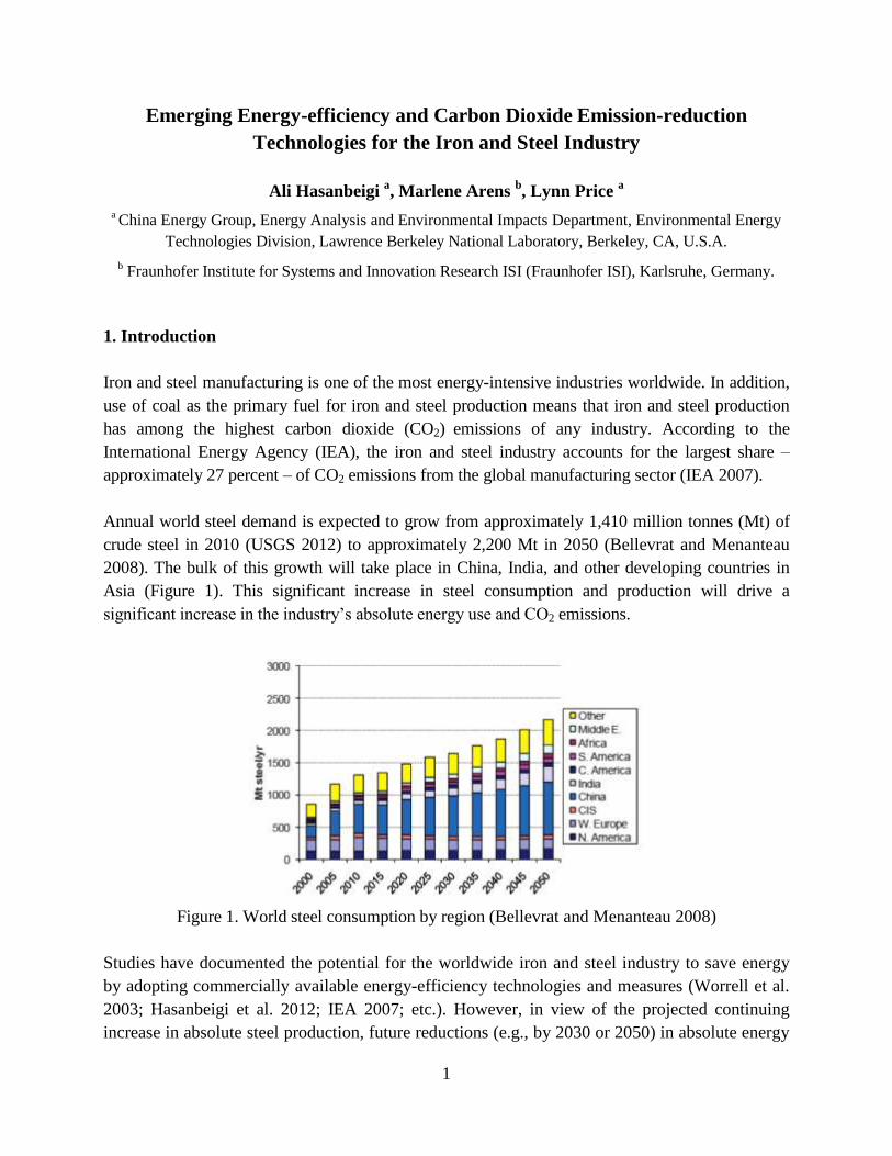
Annual world steel demand is expected to grow from approximately 1,410 million tonnes (Mt) of
crude steel in 2010 (USGS 2012) to approximately 2,200 Mt in 2050 (Bellevrat and Menanteau
2008). The bulk of this growth will take place in China, India, and other developing countries in
Asia (Figure 1). This significant increase in steel consumption and production will drive a
significant increase in the industry’s absolute energy use and CO2 emissions.
Figure 1. World steel consumption by region (Bellevrat and Menanteau 2008)
Studies have documented the potential for the worldwide iron and steel industry to save energy
by adopting commercially available energy-efficiency technologies and measures (Worrell et al.
2003; Hasanbeigi et al. 2012; IEA 2007; etc.). However, in view of the projected continuing
increase in absolute steel production, future reductions (e.g., by 2030 or 2050) in absolute energy
2
use and CO2 emissions will require innovation beyond technologies that are available today. New
developments will likely include different processes and materials as well as technologies that
can economically capture and store the industry’s CO2 emissions. Deployment of these new
technologies in the market will be critical to the industry’s climate change mitigation strategies
for the mid and long term. It should be noted that the technology adoption in regions around the
world is driven by economic viability, raw materials availability, energy type used and energy
cost as well as regulatory regime.
Many studies from around the world have identified sector-specific (e.g., Worrell et al. 2010;
AISI 2010; EPA 2010; APP 2010; EIPPCB 2010) and cross-cutting (e.g., U.S. DOE/AMO 2012)
energy-efficiency technologies for the iron and steel industry that are already commercially
available. However, information is limited and not easily accessible regarding emerging or
advanced energy-efficiency and low-carbon technologies for the industry that have not yet been
commercialized. This report consolidates the available information on emerging technologies for
the iron and steel industry to assist engineers, researchers, investors, iron and steel companies,
policy makers, and other interested parties.
The information presented in this report is collected from publically available sources and covers
the main emerging energy-efficiency and low-carbon technologies for the iron and steel industry;
however, the list of emerging technologies addressed is not exhaustive.
The report uses a uniform structure to present information about each of the 56 technologies
covered. First, we describe the technology, including background, theory, pros and cons, barriers
and challenges, and case studies if available. Next, we present the energy, environmental, and
other benefits of the technology as well as cost information if available. For most technologies,
we include a block diagram or picture. Finally, we identify the commercialization status of each
technology as well as resources for further information. The commercialization status of each
technology is as of the writing of this report and uses the following categories:
Research stage: The technology has been studied, but no prototype has been developed.
Development stage: The technology is being studied in the laboratory, and a prototype has
been developed.
Pilot stage: The technology is being tested at an industrial-scale pilot plant.
Demonstration stage: The technology is being demonstrated and tested at the industrial
scale in more than one plant but has not yet been commercially proven.
Commercial with very low adoption rate stage: The technology is proven and is being
commercialized but has a very small market share.
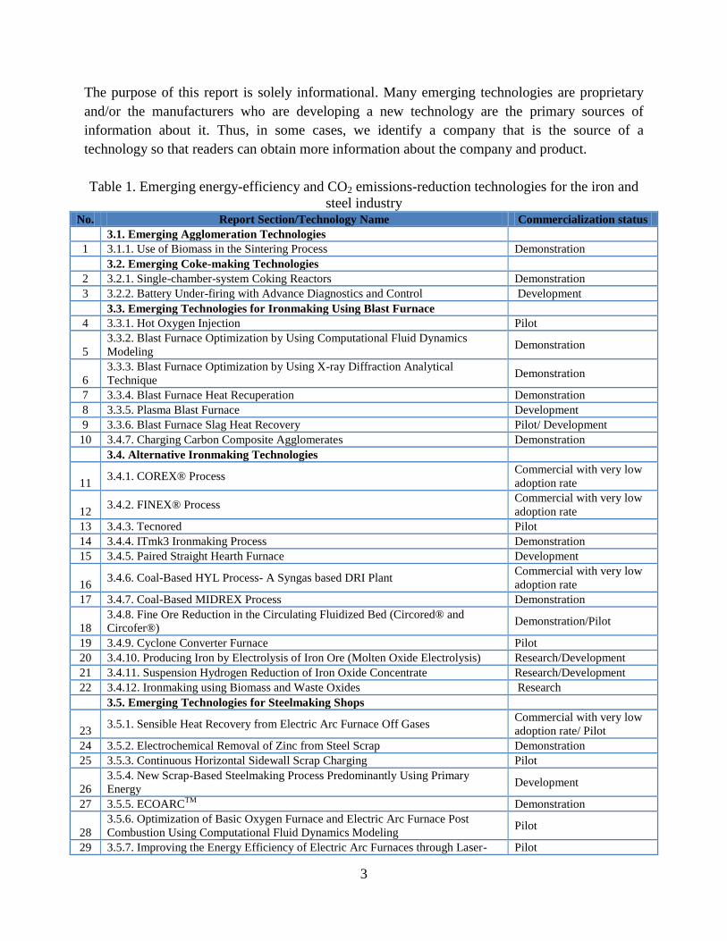
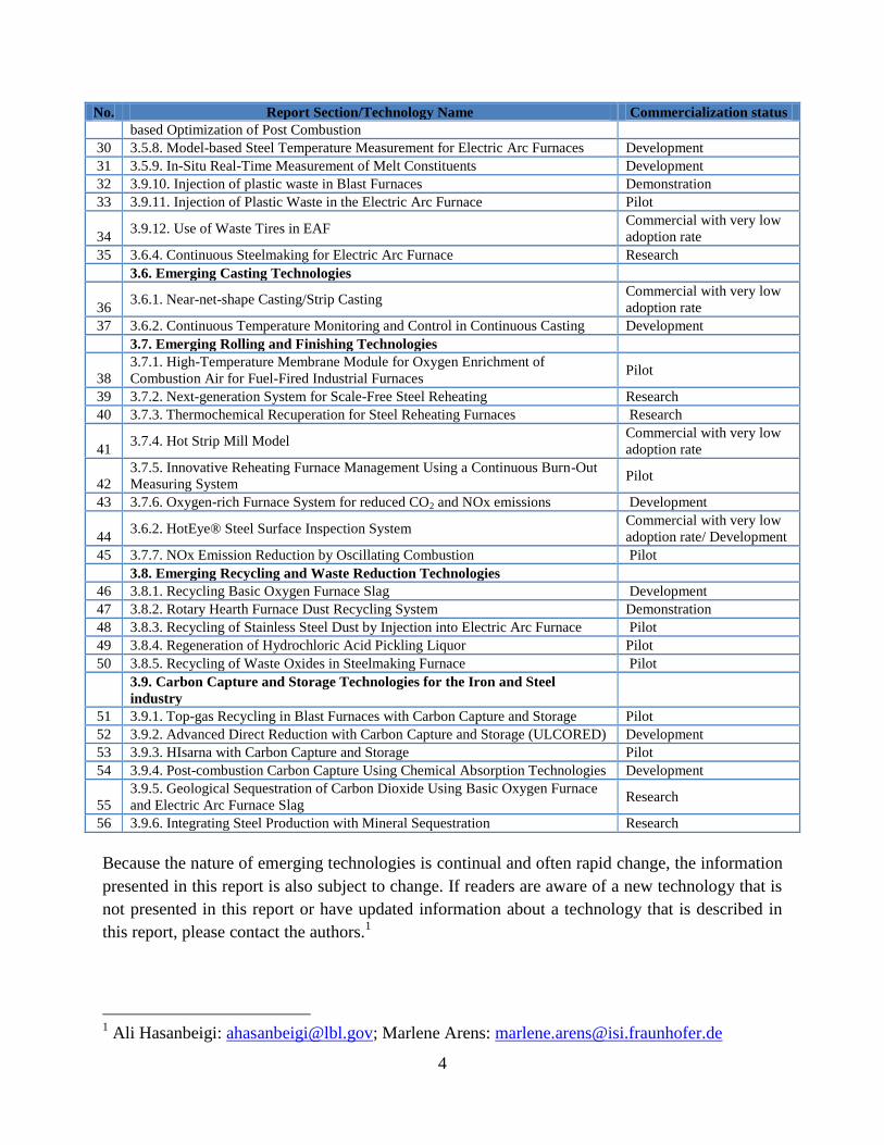
Table 1 lists the 56 technologies covered in this report, the section of the report in which each
technology is discussed, and the technology’s commercialization status.
3
The purpose of this report is solely informational. Many emerging technologies are proprietary
and/or the manufacturers who are developing a new technology are the primary sources of
information about it. Thus, in some cases, we identify a company that is the source of a
technology so that readers can obtain more information about the company and product.
Table 1. Emerging energy-efficiency and CO2 emissions-reduction technologies for the iron and
steel industry No. Report Section/Technology Name Commercialization status
3.1. Emerging Agglomeration Technologies
1 3.1.1. Use of Biomass in the Sintering Process Demonstration
3.2. Emerging Coke-making Technologies
2 3.2.1. Single-chamber-system Coking Reactors Demonstration
3 3.2.2. Battery Under-firing with Advance Diagnostics and Control Development
3.3. Emerging Technologies for Ironmaking Using Blast Furnace
4 3.3.1. Hot Oxygen Injection Pilot
5
3.3.2. Blast Furnace Optimization by Using Computational Fluid Dynamics
Modeling Demonstration
6
3.3.3. Blast Furnace Optimization by Using X-ray Diffraction Analytical
Technique Demonstration
7 3.3.4. Blast Furnace Heat Recuperation Demonstration
8 3.3.5. Plasma Blast Furnace Development
9 3.3.6. Blast Furnace Slag Heat Recovery Pilot/ Development
10 3.4.7. Charging Carbon Composite Agglomerates Demonstration
3.4. Alternative Ironmaking Technologies
11 3.4.1. COREX® Process
Commercial with very low
adoption rate
12 3.4.2. FINEX® Process
Commercial with very low
adoption rate
13 3.4.3. Tecnored Pilot
14 3.4.4. ITmk3 Ironmaking Process Demonstration
15 3.4.5. Paired Straight Hearth Furnace Development
16 3.4.6. Coal-Based HYL Process- A Syngas based DRI Plant
Commercial with very low
adoption rate
17 3.4.7. Coal-Based MIDREX Process Demonstration
18
3.4.8. Fine Ore Reduction in the Circulating Fluidized Bed (Circored® and
Circofer®) Demonstration/Pilot
19 3.4.9. Cyclone Converter Furnace Pilot
20 3.4.10. Producing Iron by Electrolysis of Iron Ore (Molten Oxide Electrolysis) Research/Development
21 3.4.11. Suspension Hydrogen Reduction of Iron Oxide Concentrate Research/Development
22 3.4.12. Ironmaking using Biomass and Waste Oxides Research
3.5. Emerging Technologies for Steelmaking Shops
23 3.5.1. Sensible Heat Recovery from Electric Arc Furnace Off Gases
Commercial with very low
adoption rate/ Pilot
24 3.5.2. Electrochemical Removal of Zinc from Steel Scrap Demonstration
25 3.5.3. Continuous Horizontal Sidewall Scrap Charging Pilot
26
3.5.4. New Scrap-Based Steelmaking Process Predominantly Using Primary
Energy Development
27 3.5.5. ECOARCTM
Demonstration
28
3.5.6. Optimization of Basic Oxygen Furnace and Electric Arc Furnace Post
Combustion Using Computational Fluid Dynamics Modeling Pilot
29 3.5.7. Improving the Energy Efficiency of Electric Arc Furnaces through Laser- Pilot
4
No. Report Section/Technology Name Commercialization status
based Optimization of Post Combustion
30 3.5.8. Model-based Steel Temperature Measurement for Electric Arc Furnaces Development
31 3.5.9. In-Situ Real-Time Measurement of Melt Constituents Development
32 3.9.10. Injection of plastic waste in Blast Furnaces Demonstration
33 3.9.11. Injection of Plastic Waste in the Electric Arc Furnace Pilot
34 3.9.12. Use of Waste Tires in EAF
Commercial with very low
adoption rate
35 3.6.4. Continuous Steelmaking for Electric Arc Furnace Research
3.6. Emerging Casting Technologies
36 3.6.1. Near-net-shape Casting/Strip Casting
Commercial with very low
adoption rate
37 3.6.2. Continuous Temperature Monitoring and Control in Continuous Casting Development
3.7. Emerging Rolling and Finishing Technologies
38
3.7.1. High-Temperature Membrane Module for Oxygen Enrichment of
Combustion Air for Fuel-Fired Industrial Furnaces Pilot
39 3.7.2. Next-generation System for Scale-Free Steel Reheating Research
40 3.7.3. Thermochemical Recuperation for Steel Reheating Furnaces Research
41 3.7.4. Hot Strip Mill Model
Commercial with very low
adoption rate
42
3.7.5. Innovative Reheating Furnace Management Using a Continuous Burn-Out
Measuring System Pilot
43 3.7.6. Oxygen-rich Furnace System for reduced CO2 and NOx emissions Development
44 3.6.2. HotEye® Steel Surface Inspection System
Commercial with very low
adoption rate/ Development
45 3.7.7. NOx Emission Reduction by Oscillating Combustion Pilot
3.8. Emerging Recycling and Waste Reduction Technologies
46 3.8.1. Recycling Basic Oxygen Furnace Slag Development
47 3.8.2. Rotary Hearth Furnace Dust Recycling System Demonstration
48 3.8.3. Recycling of Stainless Steel Dust by Injection into Electric Arc Furnace Pilot
49 3.8.4. Regeneration of Hydrochloric Acid Pickling Liquor Pilot
50 3.8.5. Recycling of Waste Oxides in Steelmaking Furnace Pilot
3.9. Carbon Capture and Storage Technologies for the Iron and Steel
industry
51 3.9.1. Top-gas Recycling in Blast Furnaces with Carbon Capture and Storage Pilot
52 3.9.2. Advanced Direct Reduction with Carbon Capture and Storage (ULCORED) Development
53 3.9.3. HIsarna with Carbon Capture and Storage Pilot
54 3.9.4. Post-combustion Carbon Capture Using Chemical Absorption Technologies Development
55
3.9.5. Geological Sequestration of Carbon Dioxide Using Basic Oxygen Furnace
and Electric Arc Furnace Slag Research
56 3.9.6. Integrating Steel Production with Mineral Sequestration Research
Because the nature of emerging technologies is continual and often rapid change, the information
presented in this report is also subject to change. If readers are aware of a new technology that is
not presented in this report or have updated information about a technology that is described in
this report, please contact the authors.1
1 Ali Hasanbeigi: [email protected]; Marlene Arens: [email protected]
5
2. Description of Iron and Steel Production
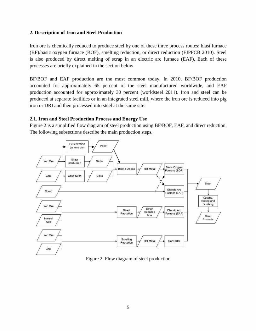
Iron ore is chemically reduced to produce steel by one of these three process routes: blast furnace
(BF)/basic oxygen furnace (BOF), smelting reduction, or direct reduction (EIPPCB 2010). Steel
is also produced by direct melting of scrap in an electric arc furnace (EAF). Each of these
processes are briefly explained in the section below.
BF/BOF and EAF production are the most common today. In 2010, BF/BOF production
accounted for approximately 65 percent of the steel manufactured worldwide, and EAF
production accounted for approximately 30 percent (worldsteel 2011). Iron and steel can be
produced at separate facilities or in an integrated steel mill, where the iron ore is reduced into pig
iron or DRI and then processed into steel at the same site.
2.1. Iron and Steel Production Process and Energy Use
Figure 2 is a simplified flow diagram of steel production using BF/BOF, EAF, and direct reduction.
The following subsections describe the main production steps.
Figure 2. Flow diagram of steel production
Pellet Pelletization
(at mine cite)
6
2.1.1. Raw Materials
The subsections below describe the preparation of raw materials for iron and steel production.
Sintering
In sintering, iron ore fines, other iron-bearing wastes, and coke dust are blended and combusted;
the heat induces incipient fusion to convert the fines into coarse lumps (sinter) that can be used as
raw material (charge) in a BF. Sintering enables manufacturers to use iron ore fines and other
iron bearing wastes but requires a large capital investment and air pollution controls (APP 2010).
According to Energetics, Inc. (2004), the range of energy use for sintering is 1.5 to 1.7 gigajoules
per ton (GJ/t). Sinter plants are mostly located at integrated steelworks.
Pelletizing
In pelletizing, iron ore is crushed and ground to remove impurities. The resulting beneficiated
(iron-rich) ore is mixed with a binding agent and then heated to create durable, marble-sized
pellets. These pellets can be used in both BF and direct reduction steel manufacturing (APP
2010). Pellet plants are mostly located at mining sites. Worldsteel (n.d.) estimates the energy
consumed by pelletizing at 2.1 GJ/t pellet.
Coke Making
Coke is a carbon product formed by thermal distillation of metallurgical coal at high temperatures
in the absence of air. Coke is produced in batteries of coke ovens. Coke is used to provide a
reducing atmosphere in a BF and is also a source of fuel. One of the key characteristic of coke is
its porosity which enables the gas exchange throughout the BF from the bottom to the top.
Approximately one-third of the cleaned coke oven gas (COG) is used to fuel the coke ovens, and
the remainder is used in other steel plant combustion units. Some newer coke plants use non-
recovery coke ovens that burn rather than recover the byproducts. The new non-recovery coke
plants capture combustion waste heat to generate steam and electricity. The primary CO2
emissions point at coke plants is the combustion stack from the ovens (U.S. EPA 2010).
Energetics, Inc. (2004) gives the range of energy use for coke making as 5.5 – 6.5 GJ/t coke 2.
2.1.2. Ironmaking
The subsections below describe three ironmaking processes, i.e. the BF, direct reduction, and
smelting reduction processes.
Blast Furnace
A BF is a huge shaft furnace that is top fed with iron ore, coke, and limestone. These materials
form alternating layers in the furnace and are supported on a bed of incandescent coke. Hot air is
blown through an opening into the bottom of the furnace and passes through the porous bed. The
coke combusts, producing heat and carbon monoxide (CO) gas. The heat melts the charge, and
the CO removes the oxygen from the iron ore, producing hot metal3. Hot metal is a solution of
2 Full credit is taken for off-gas and by-product energy.
3 When hot metal is allowed to solidify in a pig iron casting machine, the resultant solid iron is called pig iron.
7
molten iron at approximately 1,480ºC, which contains 4 percent carbon and some Silicon. This
hot metal flows to the bottom of the furnace, through the coke bed and is periodically “tapped”
from the furnace into transfer cars and transported to the BOF where it is refined into steel. The
BF is the most energy-intensive step in the BF/BOF steelmaking process, generating large
quantities of CO2 (AISI 2010). Energetics, Inc. (2004) gives a range of energy use of 13.0 to 14.1
GJ/t pig iron.
Direct Reduction
Direct reduction is the removal (reduction) of oxygen from iron ore in its solid state. This
technology encompasses a broad group of processes based on different feedstocks, furnaces,
reducing agents, etc. Natural gas (and in some cases coal) is used as a reducing agent to enable
this process. In 2000, 92.6 percent of direct reduction worldwide was based on natural gas and
took place in shaft furnaces, retorts, and fluidized bed reactors. The metallization rate of the end
product, called Direct Reduced Iron (DRI) or ‘sponge iron’, ranges from 85 percent to 95 percent
(often even higher). In 2008, 68.5 Mt of DRI was produced worldwide, using primarily MIDREX
technology (58.2 percent). The MIDREX process typically consists of four stages: 1) reduction, 2)
reforming, 3) heat recovery, and 4) briquette making. A mixture of pellets or lump ore, possibly
including up to 10 percent fine ore, enters the furnace shaft. As the ore descends, oxygen is
removed by counter-flowing reduction gas, which is enriched with hydrogen and CO (IEA 2010).
The iron is then formed into briquettes, and heat from the process is recovered.
Smelting Reduction
Smelting reduction iron (SRI) is an alternative to the BF, as it also produces liquid iron. Smelting
reduction was developed to overcome the need for the energy-intensive products- coke and sinter
(if sinter is used in BF). Instead smelting reduction is aimed to use coal and iron fines. Several
processes are under development; some have been commercially proven (COREX, FINEX,
ITmk3), others are under demonstration (e.g. Hismelt). Iron ore first undergoes a solid-state
reduction in a pre-reduction unit. The resulting product at this stage - similar to DRI - is then
smelted and further reduced in the smelting reduction vessel where coal is gasified, producing
heat and CO-rich hot gas that can be further oxidized to generate additional heat to smelt the iron.
Coal gasification is the result of a reaction with oxygen and iron ore in a liquid state. The heat is
used to smelt iron and the hot gas is transported to the pre-reduction unit to reduce the iron oxides
that enter the process. This process is called post-combustion and leads to a tradeoff in the
utilization of the gas between increased pre-reduction potential or increased heat delivery for
smelting (IEA 2010). Commercial smelting reduction is still dominated by first-generation
processes, notably the COREX process developed in Germany and Austria (IEA 2010).
2.1.3. Steelmaking
The subsections below describe the steelmaking process with BOF or EAF.
8
Basic Oxygen Furnace (BOF)
The BOF converts liquid hot metal from the BF into steel. The main operation is the addition of
oxygen to remove carbon from the hot metal. In recent years, extensive ladle metallurgy
processes have been developed to improve steel quality. Few energy data are available for these
operations. A BOF uses virtually no energy and does not produce net energy (IEA 2007).
Electric Arc Furnace (EAF)
EAFs are mainly used to produce steel by recycling ferrous scrap. But also DRI and pig iron can
be fed to the EAF as a scrap substitute. EAFs are equipped with carbon electrodes that can be
raised or lowered through the furnace roof to provide the necessary energy by an electric arc.
Energy consumption in EAF-steelmaking is much lower, as the energy-intense reduction of iron
ore has already been carried out in the BF (or in the DRI or SR plant). EAF steelmaking can use
a wide range of scrap types, direct reduced iron (DRI), pig iron and molten iron (up to 30 percent)
as the feed charge. The liquid steel from an EAF is generally sent to a Ladle Metallurgy Station
(LMS) now-a-days to improve the steel quality. Recycling of scrap into steel saves virgin raw
materials as well as the energy required for converting them (APP 2010). Energetics, Inc. (2004)
gives a range of energy use for EAFs as 2.1 to 2.4 GJ/t crude steel.
2.1.4. Casting, Rolling, and Finishing
The molten steel produced by both BOFs and EAFs follows similar routes after leaving the
furnace: it is transferred from the LMS to the continuous caster, which forms the steel into semi-
finished shapes (e.g., slabs, blooms, billets, rounds, and other special sections). Steel from the
continuous caster is mainly processed in rolling mills to produce the final shapes that are sold by
the steel mill. These shapes include coiled strips, rails, sheets, many structural shapes, rods and
bars. Because rolling mills consume electricity, they contribute to indirect greenhouse gas
emissions. Fossil fuels (e.g. natural gas) are consumed in furnaces to reheat the steel before
rolling. The products from the hot rolling mill may be further processed in various ways, such as
annealing, hot forming, cold rolling, heat treating (tempering), pickling, galvanizing, coating, or
painting. The furnaces are custom designed for the type of steel, the dimensions of the semi-
finished steel pieces, and the desired temperature (U.S. EPA 2010). Energetics, Inc. (2004) gives
the range of 2.0 – 2.4 GJ/t steel and 1.0 – 1.4 GJ/t steel for energy use of hot rolling (flat) and
cold rolling (flat), respectively.
2.2. CO2 Impact of Iron and Steel Production
Iron and steel production generates CO2 emissions as 1) process emissions, in which raw
materials and combustion both may contribute to CO2 emissions; 2) emissions from combustion
sources alone; and 3) indirect emissions from consumption of electricity (primarily in EAFs and
in finishing operations such as rolling mills at both integrated steel plants and EAF plants) (U.S.
EPA 2010).
9
The major process units at iron and steel facilities where raw materials, usually in combination
with fuel combustion, contribute to CO2 emissions include the sinter plant, non-recovery coke
oven battery combustion stack, coke pushing, BF exhaust, BOF exhaust, and EAF exhaust (U.S.
EPA 2010). The primary combustion sources of CO2 include: byproduct recovery coke oven
battery combustion stack, BF stove, boiler, process heater, reheat furnace, flame-suppression
system, annealing furnace, flare; ladle reheater, and other miscellaneous (U.S. EPA 2010).
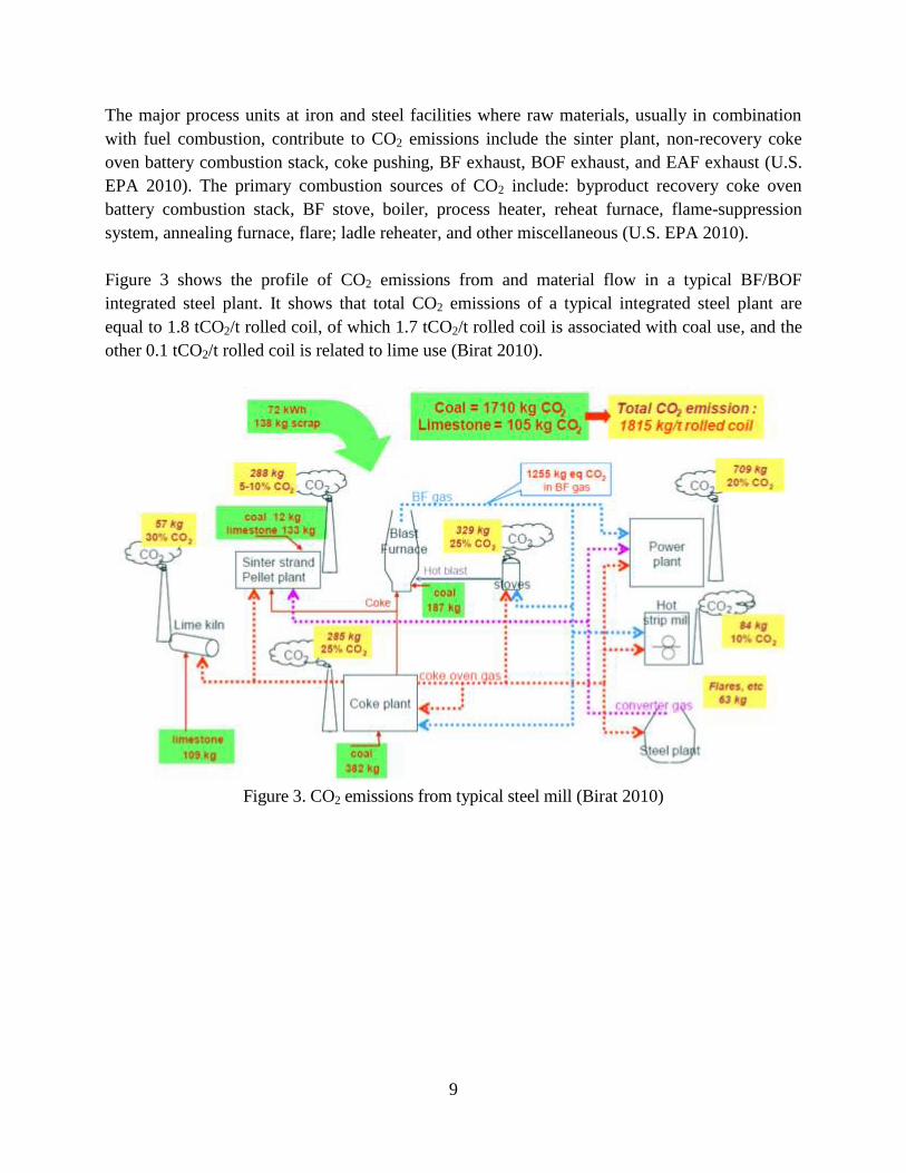
Figure 3 shows the profile of CO2 emissions from and material flow in a typical BF/BOF
integrated steel plant. It shows that total CO2 emissions of a typical integrated steel plant are
equal to 1.8 tCO2/t rolled coil, of which 1.7 tCO2/t rolled coil is associated with coal use, and the
other 0.1 tCO2/t rolled coil is related to lime use (Birat 2010).
Figure 3. CO2 emissions from typical steel mill (Birat 2010)
10
3. Emerging Energy-efficiency and CO2 Emissions Reduction Technologies
The subsections below describe emerging energy-efficiency and CO2 emissions reduction
technologies for the iron- and steelmaking process.
3.1. Emerging Agglomeration Technology
Iron ore agglomeration can improve the iron content and/or physical properties of the ore. Iron
feed materials from such processes usually contain between 50 percent to 70 percent iron by
weight. The main agglomeration processes are sintering and pelletizing. Below an emerging
technology that can be applied to this stage of iron production is presented.
3.1.1. Use of Biomass in the Sintering Process
Description:
The iron-ore sintering process contributes up to 10 percent of the CO2 emissions from an
integrated iron and steel plant (Ooi et al. 2011). This process requires the ignition of a solid fuel
(usually coke breeze), which is blended into the raw feed material. A suitable alternative fuel
must be solid and have downdraft combustion characteristics similar to those of coke breeze.
Charcoal is an attractive alternative to coke breeze because charcoal is derived from biomass and
therefore considered to be carbon neutral. Charcoal has been found to be as effective a fuel and
reductant as high quality coals for the bath smelting of iron ores (Ooi et al. 2011; APP 2010).
A variety of wood char products are produced using relatively new processes such as gasification,
slow pyrolysis, and fast pyrolysis (Ooi et al. 2011). Wood char has been shown to be a suitable
replacement for coke breeze, improving the sintering process and reducing acid gas levels in
process emissions (APP 2010). It should be noted that it is possible that only a limited amount of
charcoal would be available when competition with other routes of biomass use is considered.
Ooi et al. (2011) conducted a laboratory study of the use of hardwood charcoal as a
supplementary fuel in the iron-ore sintering process. The primary fuel was coke breeze; the study
tested 0 percent, 20 percent, 50 percent, and 100 percent replacement with charcoal, producing
raw blends with the same heat output as coke breeze. The experimental results indicate that fuel
blends with 20 percent heat input provided by charcoal may improve both sinter yield and
sintering productivity by up to 8 percent under normal conditions. When larger percentages of
coke breeze were replaced with charcoal, reduced sintering performance was observed, which
was mainly attributed to the lower fixed carbon content and higher volatile matter content of the
fuel mix (Ooi et al. 2011).
Zandi et al. (2010) studied commercially available biomass materials suited to sintering: olive
residues, sunflower husk pellets, almond shells, hazelnut shells, and bagasse pellets. A laboratory
11
sinter pot was used to study the sintering behavior of these biomass materials. The calorific
values of selected biomass materials, on a dry basis, were, on average, approximately 65 percent
that of dry coke breeze. However, less of this energy was available in sinter making because
some of the volatile matter evaporated ahead of the flame front. Replacing 25 of coke breeze with
crushed sunflower husk pellets produced a thermal profile closest to that of coke breeze alone in
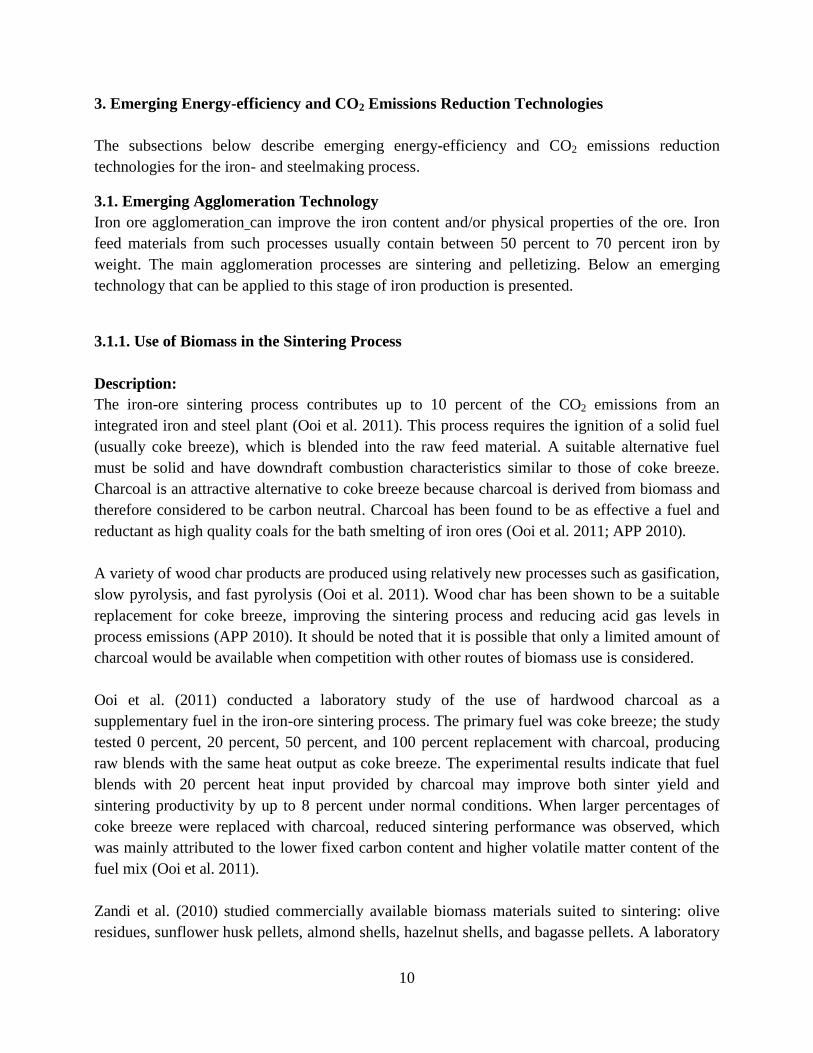
some size ranges of sunflower husk pellets (Zandi et al. 2010). Figure 4 shows a schematic
drawing of an iron-ore sintering plant.
Energy/Environment/Cost/Other Benefits:
The following benefits can be achieved by replacing a portion of the coke breeze fuel with biomass
fuel in sintering plants (Ooi et al. 2011; APP 2010):
Substantial reductions in CO2 emissions because biomass is considered carbon neutral
Reduced acid gas emissions
Improved carburization rates and increased product quality
Reduced demand for fluxing agents
Lower slag volume and levels of process wastes
Higher productivity through use of more reactive carbon
Block Diagram or Photo:
Figure 4. Schematic diagram of an iron-ore sintering plant (Ooi et al. 2011)
Commercial Status: Demonstration stage
References for further information:
Ooi et al. (2011), APP (2010), Zandi (2010)
12
3.2. Emerging Coke-Making Technologies
The subsections below describe the following emerging technologies to reduce the energy use
and CO2 emissions of the coke-making process: single-chamber coke reactors and battery under-
firing with advanced controls.
3.2.1. Single-chamber-system Coking Reactors
Description:
Single-chamber-system (SCS) coking reactors are large-volume coke ovens that are 45 to 85
centimeters wide. Single-chamber reactors are separate, process-controlled units with rigid walls
that can absorb high coking pressure. The single-chamber design allows much thinner heating
walls than in other systems. This enhances heat transfer and combustion and allows for greater
design flexibility in the plant (EIPPCB 2001).
The load-bearing capacity of the single-chamber reactor walls means that a greater range of coal
blends can be charged than in conventional coke ovens. (Rohde and Strunk [1998] compared the
coking behavior of coal blends in the single chamber system and in conventional high-capacity
coke ovens.) The large-dimension oven in the SCS design reduces environmental emissions
compared to those from multi-chamber reactors. SCS coke ovens are expected to take the place
of current multi-chamber coke ovens whose walls have more limited flexibility. SCSs are 38- to
70-percent more thermally efficient than other coke ovens. The SCS technology is currently
under development. An SCS coke reactor operating in Germany was relocated to China a few
years ago (Worrell et al. 2010).
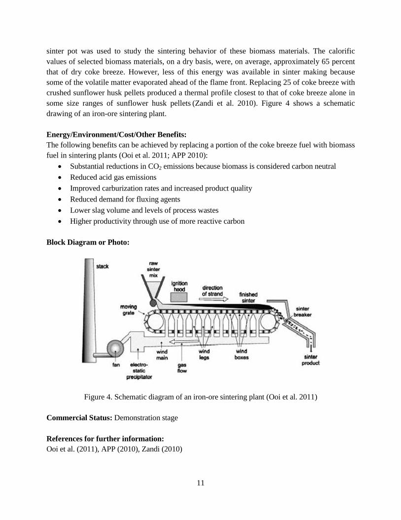
Figure 5 shows a schematic drawing of the single-chamber system.
Energy/Environment/Cost/Other Benefits:
The following benefits are reported for SCS coking reactors compared to conventional multi-
chamber coking reactors (Worrell et al. 2010; Nashan 2007):
Reduced coking time
Improved productivity
Increased coke strength
Reduced space requirement, which increases design flexibility of the plant
Ability to use wider range of coal, particularly coals containing less volatile matter, thus
yielding a higher coke output
Lower coke reactivity index values and higher coke strength after reaction values
compared to those of conventional systems using similar coal
Lower capital investment costs than for conventional ovens, particularly from
implementing lean oven chambers
13
Estimated capital investment of approximately $40 million for 100,000 t of BF coke per
year; estimated cost savings of 10 $/t coke or higher
Utilization of coke oven gas as energy carrier, reducing agent for iron ore, and synthesis
gas in chemical plants
Lower maintenance costs
Reduced CO2 emissions
Block Diagram or Photo:
Figure 5. Schematic diagram of the single-chamber system (D ez et al. )
Commercial Status:
Demonstration stage
References for further information:
EIPPCB (2001), Worrell et al. (2010), Nashan (2007)
3.2.2. Coke Oven Under-firing with Advanced Diagnostics and Control
Description:
Heating coke ovens produces significant amount of the pollutants nitrogen oxide (NOx) and
sulfur dioxide (SO2). Therefore, improving energy efficiency of coke ovens is a cost-effective
way to reduce pollutant emissions as well as energy demand (BFI 2009/2010). A VDEh-
Betriebsforschungsinstitut (BFI) project developed individual control of the heating walls of coke
ovens as well as innovative diagnostic systems that can detect disturbances in the heating walls
(e.g., raw gas escaping from the coke wall or blockage of the combustion gas and air nozzles). A
test reactor (see Figure 6) was used to study factors that influence the composition of the off gas
and the temperature distribution in the heating flues; these factors include combustion gas supply
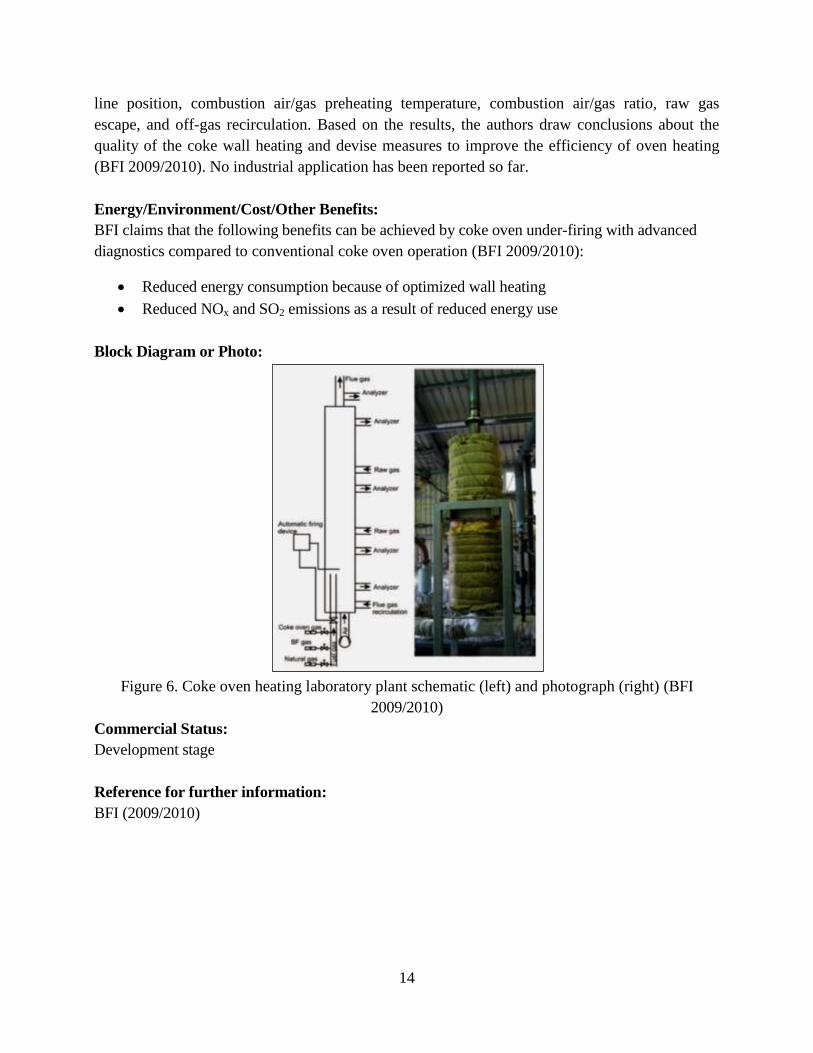
14
line position, combustion air/gas preheating temperature, combustion air/gas ratio, raw gas
escape, and off-gas recirculation. Based on the results, the authors draw conclusions about the
quality of the coke wall heating and devise measures to improve the efficiency of oven heating
(BFI 2009/2010). No industrial application has been reported so far.
Energy/Environment/Cost/Other Benefits:
BFI claims that the following benefits can be achieved by coke oven under-firing with advanced
diagnostics compared to conventional coke oven operation (BFI 2009/2010):
Reduced energy consumption because of optimized wall heating
Reduced NOx and SO2 emissions as a result of reduced energy use
Block Diagram or Photo:
Figure 6. Coke oven heating laboratory plant schematic (left) and photograph (right) (BFI
2009/2010)
Commercial Status:
Development stage
Reference for further information:
BFI (2009/2010)
15
3.3. Emerging Technologies for Ironmaking Using Blast Furnace
The subsections below describe the following emerging technologies to reduce energy use and
CO2 emissions from the BF ironmaking process
3.3.1. Hot Oxygen Injection
Description:
Injection of pulverized coal directly into the BF bypasses the coke making process and injects
coal directly into the BF at the tuyere level. Pulverized coal injection (PCI) is not a new
technology, but, until now, the amount of coal that could be injected into the furnace was limited
to 116 to 150 kilograms (kg)/t hot metal (AISI 2010) because of incomplete combustion of char
in the tuyere zone and consequent disturbances in gas and burden flow in the furnace (Halder
2011). Increased coal injection is needed to further lower coke requirements and allow for more
flexible furnace productivity. The direct injection of high-temperature oxygen with coal in the BF
blowpipe and tuyere offers better coal dispersion at high local oxygen concentrations, which
optimizes oxygen use in the BF (Riley 2002; U.S. DOE/ITP 2010a).
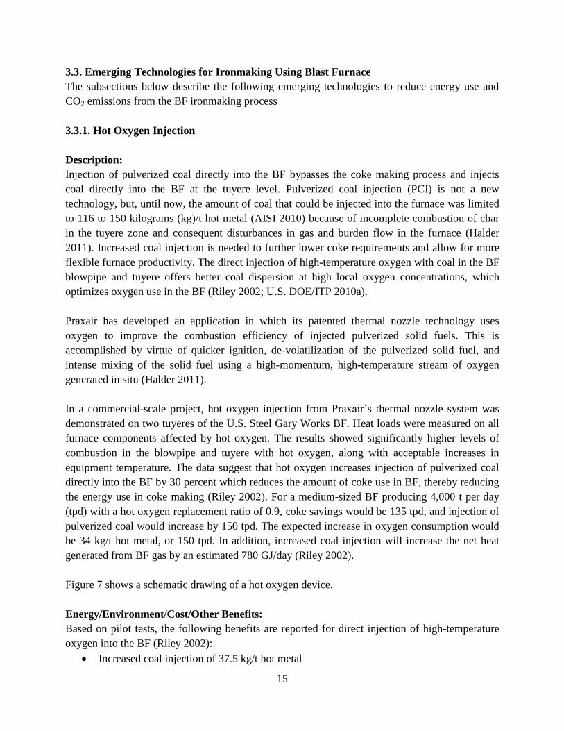
Praxair has developed an application in which its patented thermal nozzle technology uses
oxygen to improve the combustion efficiency of injected pulverized solid fuels. This is
accomplished by virtue of quicker ignition, de-volatilization of the pulverized solid fuel, and
intense mixing of the solid fuel using a high-momentum, high-temperature stream of oxygen
generated in situ (Halder 2011).
In a commercial-scale project, hot oxygen injection from Praxair’s thermal nozzle system was
demonstrated on two tuyeres of the U.S. Steel Gary Works BF. Heat loads were measured on all
furnace components affected by hot oxygen. The results showed significantly higher levels of
combustion in the blowpipe and tuyere with hot oxygen, along with acceptable increases in
equipment temperature. The data suggest that hot oxygen increases injection of pulverized coal
directly into the BF by 30 percent which reduces the amount of coke use in BF, thereby reducing
the energy use in coke making (Riley 2002). For a medium-sized BF producing 4,000 t per day
(tpd) with a hot oxygen replacement ratio of 0.9, coke savings would be 135 tpd, and injection of
pulverized coal would increase by 150 tpd. The expected increase in oxygen consumption would
be 34 kg/t hot metal, or 150 tpd. In addition, increased coal injection will increase the net heat
generated from BF gas by an estimated 780 GJ/day (Riley 2002).
Figure 7 shows a schematic drawing of a hot oxygen device.
Energy/Environment/Cost/Other Benefits:
Based on pilot tests, the following benefits are reported for direct injection of high-temperature
oxygen into the BF (Riley 2002):
Increased coal injection of 37.5 kg/t hot metal
16
Potential productivity increase of 15 percent
Increase in net amount of BF gas generated
Reduced emissions of pollutants and greenhouse gases (CO2, SO2, volatile organic
compounds [VOCs], and NOx) proportional to reduced coke requirements
Estimated total capital and installation cost of $1.05 million for a 4,000-tpd furnace
Direct savings payback period (not including productivity benefits) of less than 11 months;
including productivity benefits, payback period of 3 months.
Block Diagram or Photo:
Figure 7. Schematic of hot oxygen device (Halder 2011)
Commercial Status:
Pilot stage
References for further information:
Riley (2002), U.S. DOE/ITP (2010a), Halder (2011)
3.3.2. Blast Furnace Optimization Using Computational Fluid Dynamics Modeling
Description:
One method of visualizing BF operations is by building a “virtual BF” using computational fluid
dynamics (CFD) modeling. CFD uses advanced mathematical and computing concepts to
simulate the behavior of high-pressure, high-temperature systems. Using the “virtual BF,” it is
possible to design, optimize, and troubleshoot the system and experiment with operational
improvements. CFD can be used to model increased levels of PCI. Increasing the PCI from 116–
150 kg/t hot metal to 250 kg/t hot metal would save approximately 0.33 GJ of energy/t hot metal.
Efforts to increase PCI to more than 250 kg/t hot metal have been frustrated because, at these
levels, the permeability of the BF bed decreases, shutting off gas flow. In addition, some of the
pulverized coal is wasted because it fails to combust and is blown through the BF into the gas
collection system, thus increasing the apparent energy intensity of the process (AISI 2010).
The ability to increase the amount of coal injected into BFs has been limited by lack of
knowledge of some key issues, so the U.S. DOE and American Iron and Steel Institute (AISI)
Technology Roadmap Program (DOE/AISI TR Program) supported research at Purdue
17
University-Calumet to develop high-fidelity CFD numerical simulations. To date, Purdue has
developed comprehensive three-dimensional (3-D) CFD models and methodologies to simulate
the entire PCI process. The models were created by comparing CFD results with experimental
data and were then applied to simulate the PCI process in various BFs of AISI members, using
actual furnace geometries and operating practices. The effects of key parameters, such as blast
temperature and flow rate, oxygen concentration, coal type, PCI rate, and tuyere diameter, have
been investigated.
Because fuel economy in a BF is directly coupled to the gas and burden (raw materials or the
charge) distributions in a BF, the DOE/AISI TR Program supported Purdue University-Calumet
to (AISI 2010):
Integrate all the BF CFD models developed so far, to visualize the entire BF process
Develop a state-of-the-art 3-D CFD model for simulating the gas distribution inside a BF at
given burden conditions, burden distributions, and blast parameters
Measure top temperature and gas composition distributions and validate the CFD model
Maximize gas utilization via optimized burden and gas distribution to produce the proper
furnace permeability for given burden materials, production rates, and BFs
Optimize the burden and gas distributions for high fuel-injection and low coke rates to
produce the greatest fuel efficiency for the given burden materials, productivities, and BFs
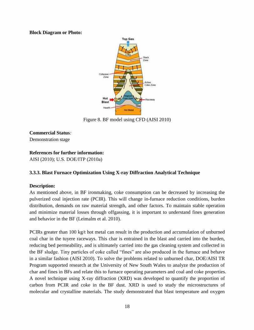
Figure 8 shows a CFD model of a BF.
Energy/Environment/Cost/Other Benefits:
The following benefits are reported for the use of CFD models for BF optimization (AISI 2010;
U.S. DOE/ITP 2010a):
Development of recommendations for design and protection of PCI lances
Troubleshooting solutions for PCI operation
Calculation of optimized BF operation for a given fuel injection rate and efficiency and
the resulting gas distribution compared to process monitoring data; enables improved BF
efficiency and productivity and lowers emissions
Reduced emissions (e.g., CO2, SO2, VOCs, and NOx) from coke making, proportional to
reduced coke requirements.
18
Block Diagram or Photo:
Figure 8. BF model using CFD (AISI 2010)
Commercial Status:
Demonstration stage
References for further information:
AISI (2010); U.S. DOE/ITP (2010a)
3.3.3. Blast Furnace Optimization Using X-ray Diffraction Analytical Technique
Description:
As mentioned above, in BF ironmaking, coke consumption can be decreased by increasing the
pulverized coal injection rate (PCIR). This will change in-furnace reduction conditions, burden
distribution, demands on raw material strength, and other factors. To maintain stable operation
and minimize material losses through offgassing, it is important to understand fines generation
and behavior in the BF (Leimalm et al. 2010).
PCIRs greater than 100 kg/t hot metal can result in the production and accumulation of unburned
coal char in the tuyere raceways. This char is entrained in the blast and carried into the burden,
reducing bed permeability, and is ultimately carried into the gas cleaning system and collected in
the BF sludge. Tiny particles of coke called “fines” are also produced in the furnace and behave
in a similar fashion (AISI 2010). To solve the problems related to unburned char, DOE/AISI TR
Program supported research at the University of New South Wales to analyze the production of
char and fines in BFs and relate this to furnace operating parameters and coal and coke properties.
A novel technique using X-ray diffraction (XRD) was developed to quantify the proportion of
carbon from PCIR and coke in the BF dust. XRD is used to study the microstructures of
molecular and crystalline materials. The study demonstrated that blast temperature and oxygen
19
influenced PCI combustion and char carryover and limited coal injection rates. The results
suggest that, by monitoring the carbon structure of residual char in the dust, PCI and coke quality
can be optimized for various process parameters. The study further demonstrated that the carbon
structure of coke fines in BF dust can be used to assess coke performance, particularly the
influence of temperature on the generation of coke fines, whether they originated in the low- or
high-temperature zones of the BF. Introduction of this XRD diagnostic tool in steel plants makes
it possible to monitor the impact of PCI rates and coke quality and thereby further boost PCI rates
(AISI 2010).
Leimalm et al. (2010) sampled the off-gas dust and shaft fines generated during operation of an
experimental BF using olivine pellets and mixtures of acid pellets and sinter as iron-bearing
materials. Characterization using XRD focused on fines from iron-bearing materials, coke, and
slag formers. Prakash et al. also used XRD to study the effective utilization of BF flue dust from
integrated steel plants (Das et al. 2002).
There are many other applications of XRD in the steel industry, including in blending of iron ores,
control of sintering behavior, quality control of DRI, and analysis of converter slag. For example,
König et al. (2010) describe how XRD can be used in mining for iron ore where distinguishing
between hematite and magnetite has a big impact both on the refining of the ore and on the
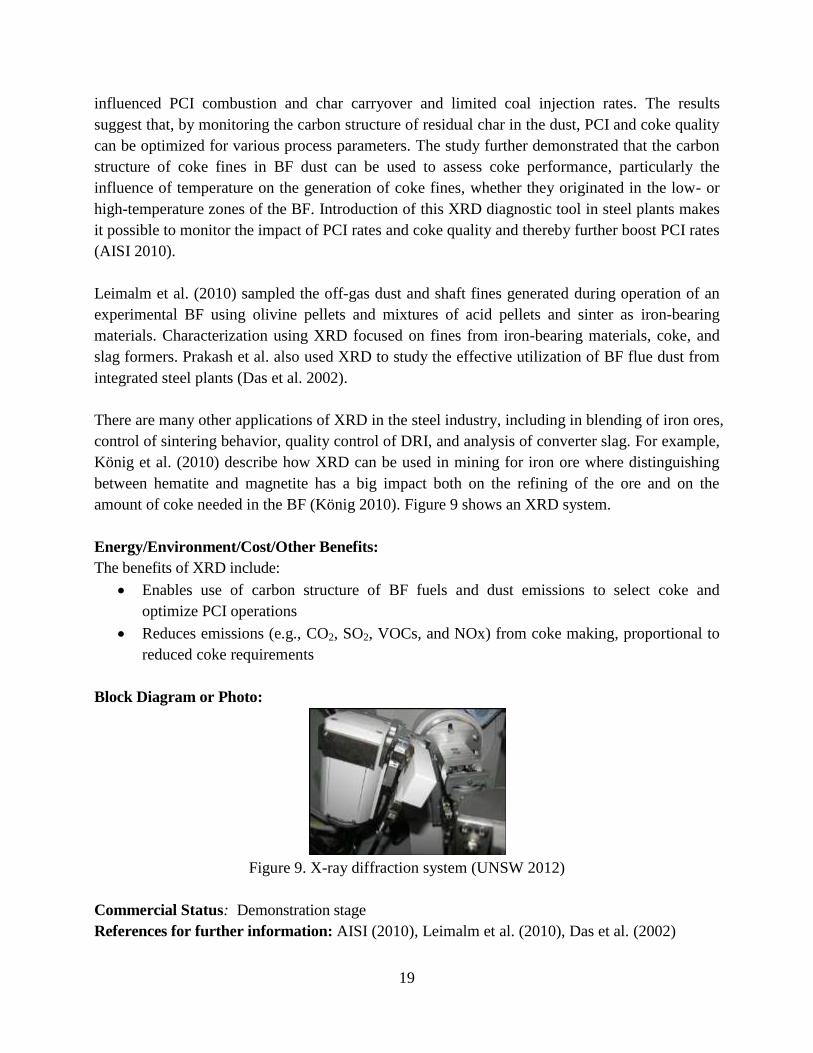
amount of coke needed in the BF (König 2010). Figure 9 shows an XRD system.
Energy/Environment/Cost/Other Benefits:
The benefits of XRD include:
Enables use of carbon structure of BF fuels and dust emissions to select coke and
optimize PCI operations
Reduces emissions (e.g., CO2, SO2, VOCs, and NOx) from coke making, proportional to
reduced coke requirements
Block Diagram or Photo:
Figure 9. X-ray diffraction system (UNSW 2012)
Commercial Status: Demonstration stage
References for further information: AISI (2010), Leimalm et al. (2010), Das et al. (2002)
20
3.3.4. Blast Furnace Heat Recuperation
Description:
The BF flue gas exit temperature is approximately 2500C. This heat can be recovered to preheat
stove combustion air. Installation of a recuperator in the furnace exhaust stream to preheat the
combustion air can save considerable amount of fuel. These savings are primarily the result of the
sensible heat increase of the combustion air and, to some extent, improved combustion efficiency.
The amount of fuel saved will depend on the exhaust gas temperature, amount of excess air used,
type of burner, and furnace control system. The cost of this technology is high and strongly
dependent on BF size, estimated at $18-20/GJ-saved, equivalent to $1.4/t hot metal (Farla et al.
1998; Rebello et al. 1980).
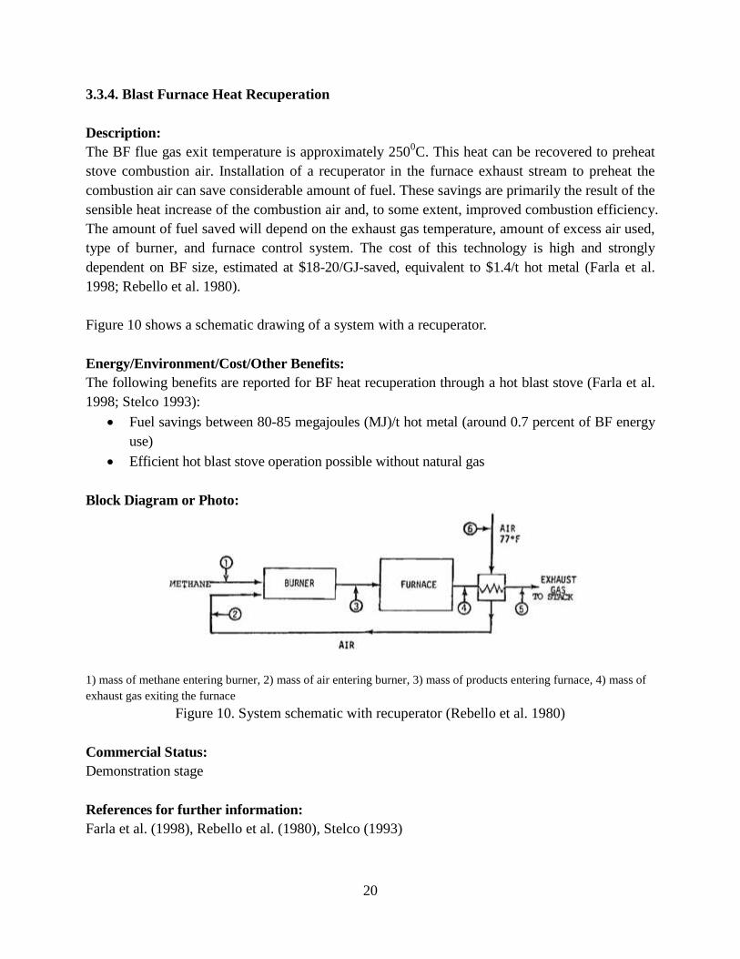
Figure 10 shows a schematic drawing of a system with a recuperator.
Energy/Environment/Cost/Other Benefits:
The following benefits are reported for BF heat recuperation through a hot blast stove (Farla et al.
1998; Stelco 1993):
Fuel savings between 80-85 megajoules (MJ)/t hot metal (around 0.7 percent of BF energy
use)
Efficient hot blast stove operation possible without natural gas
Block Diagram or Photo:
1) mass of methane entering burner, 2) mass of air entering burner, 3) mass of products entering furnace, 4) mass of
exhaust gas exiting the furnace
Figure 10. System schematic with recuperator (Rebello et al. 1980)
Commercial Status:
Demonstration stage
References for further information:
Farla et al. (1998), Rebello et al. (1980), Stelco (1993)
21
3.3.5. Plasma Blast Furnace
Description:
Today, plasma technology is being used successfully worldwide in a variety of industries from
chemical and metallurgical to waste/environmental (asbestos vitrification, fly-ash destruction)
and steel production (heat support for cupola and BF) (Solena Group, n.d.; Hacala and Michon
2009).
Plasmas are gaseous collections of electrically charged particles such as electrons and protons.
These ionized particles carry energy; in a plasma BF, the plasma flow hits the metal surface, the
ions release their energy, which melts the metal (BCS, Inc. 2005). Typical plasma power ranges
from 1 to 4 megawatts electric (MWel). Plasma torches provide high-temperature gas streams (up
to 5,000°C) (Hacala and Michon 2009). Thermal-plasma systems fall into two categories: non-
transferred-arc and transferred-arc devices. In general, transferred-arc devices have been
interfaced with open-bath furnaces in which melting or smelting processes are carried out, and
non-transferred-arc devices have normally been applied to shaft furnaces (Birat et al. 2008).
Plasma melting can raise temperatures very rapidly and is thus more energy efficient than
conventional melting technologies, for example, in non-BF applications. Plasma furnaces for
melting aluminum are reported to impart heat 60-percent faster than conventional high-rate
melters. Because of the rapid heat transfer in a plasma furnace, melting is also rapid. In aluminum
making, the energy consumption rate is as low as 0.44 kWh/kg of aluminum compared to 0.76
kWh/kg of aluminum for induction melting (BCS, Inc. 2005). These data all are for non-steel
application.
The plasma melting process also minimizes metal loss from oxidation and contamination. The
plasma keeps intact a thin oxide film on the molten metal, which protects the metal from
absorbing gases. A recent development in plasma heating converts ambient air to nitrogen,
eliminating the need to purchase nitrogen or argon, expensive gases that are required for
conventional plasma heating (BCS, Inc. 2005).
As part of the European Ultra-Low-CO2 Steelmaking program (ULCOS) program,
EUROPLASMA studied the introduction of the plasma torch in the BF top-gas recycling loop.
Calculations performed for this study showed that the use of a plasma torch fed with recycled top
gases reduced carbon consumption by 50 percent compared to that of a conventional BF
(assuming that the plasma torch is powered with low-carbon electricity). Tests showed that a 1-
megawatt (MW) plasma torch can operate with any gas mixture containing CO, diatomic
hydrogen (H2), CO2, and nitrogen (N2) (Hacala and Michon 2009). EUROPLASMA is now
moving to the next step in its torch development: developing higher-power plasma torches. The
goal is to reach 20 MWel (Hacala and Michon 2009).
22
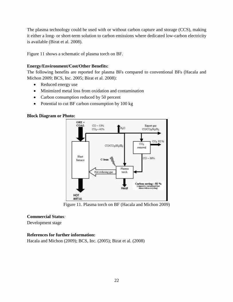
The plasma technology could be used with or without carbon capture and storage (CCS), making
it either a long- or short-term solution to carbon emissions where dedicated low-carbon electricity
is available (Birat et al. 2008).
Figure 11 shows a schematic of plasma torch on BF.
Energy/Environment/Cost/Other Benefits:
The following benefits are reported for plasma BFs compared to conventional BFs (Hacala and
Michon 2009; BCS, Inc. 2005; Birat et al. 2008):
Reduced energy use
Minimized metal loss from oxidation and contamination
Carbon consumption reduced by 50 percent
Potential to cut BF carbon consumption by 100 kg
Block Diagram or Photo:
Figure 11. Plasma torch on BF (Hacala and Michon 2009)
Commercial Status:
Development stage
References for further information:
Hacala and Michon (2009); BCS, Inc. (2005); Birat et al. (2008)
23
3.3.6. Blast Furnace Slag Heat Recovery
Description:
In modern BFs, approximately 0.25-0.30 tonne of liquid slag with temperatures ranging from
1,200 to 1,600 °C are produced per tonne of pig iron (Worrell et al. 2010; Barati et al. 2011).
Molten slag is one of the largest untapped energy sources in metal manufacturing operations.
Currently, three types of technologies are under development for utilizing the thermal energy of
slag: 1) recovery as hot air or steam, 2) conversion to chemical energy as fuel, and 3)
thermoelectric power generation. Recovery as hot air or steam is the most developed of the three,
with large-scale trials demonstrating recovery efficiencies up to 65 percent. The latter two
strategies are emerging as next-generation methods of BF slag waste heat recovery (Barati et al.
2011).
Barati et al. (2011) evaluated these three technologies and found that, for both thermal and
chemical energy recovery, a two-step process would yield a high efficiency with minimal
technical risk. For thermoelectric power generation, the use of phase-change materials appears to
solve some of the current challenges, which include the mismatch between the slag temperature
and the operating range of thermoelectric materials (Barati et al. 2011). Using a second-law
analysis, Bisio (1997) concludes that using air heated by slag heat recovery for combustion in the
hot blast stoves of the BF is preferable to producing steam from the recovered heat.
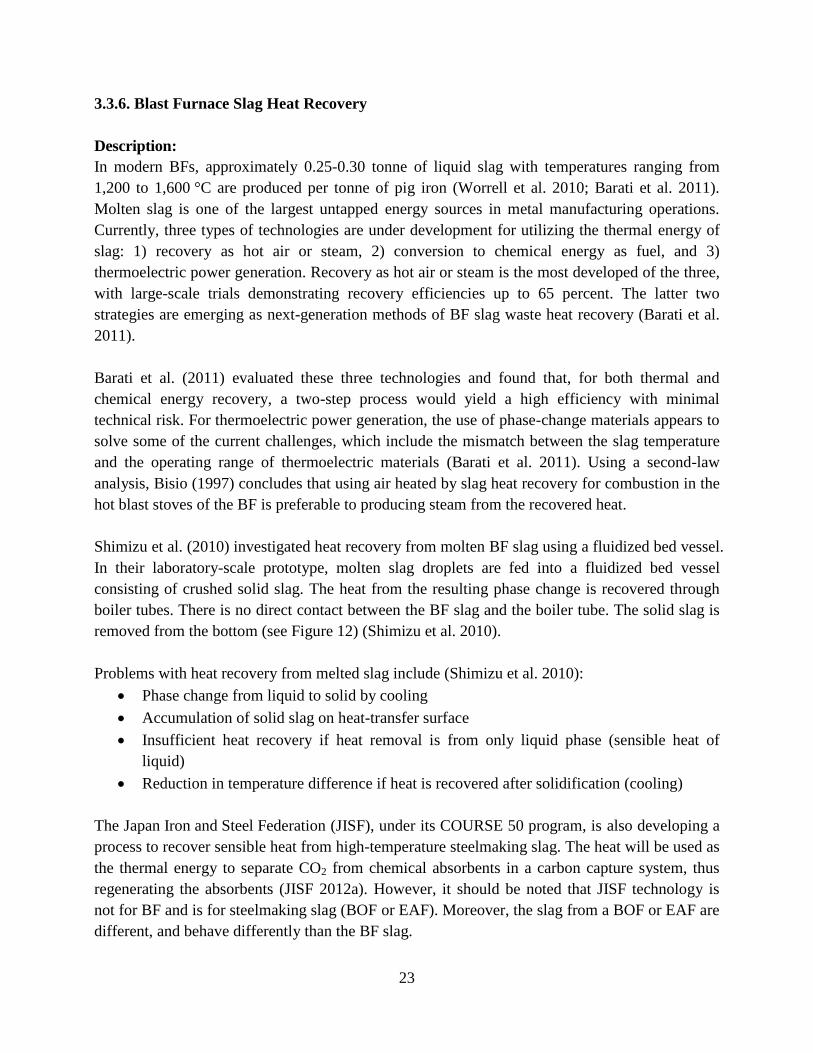
Shimizu et al. (2010) investigated heat recovery from molten BF slag using a fluidized bed vessel.
In their laboratory-scale prototype, molten slag droplets are fed into a fluidized bed vessel
consisting of crushed solid slag. The heat from the resulting phase change is recovered through
boiler tubes. There is no direct contact between the BF slag and the boiler tube. The solid slag is
removed from the bottom (see Figure 12) (Shimizu et al. 2010).
Problems with heat recovery from melted slag include (Shimizu et al. 2010):
Phase change from liquid to solid by cooling
Accumulation of solid slag on heat-transfer surface
Insufficient heat recovery if heat removal is from only liquid phase (sensible heat of
liquid)
Reduction in temperature difference if heat is recovered after solidification (cooling)
The Japan Iron and Steel Federation (JISF), under its COURSE 50 program, is also developing a
process to recover sensible heat from high-temperature steelmaking slag. The heat will be used as
the thermal energy to separate CO2 from chemical absorbents in a carbon capture system, thus
regenerating the absorbents (JISF 2012a). However, it should be noted that JISF technology is
not for BF and is for steelmaking slag (BOF or EAF). Moreover, the slag from a BOF or EAF are
different, and behave differently than the BF slag.
24
Energy/Environment/Cost/Other Benefits:
The main benefit of development of a commercial technique for slag heat recovery would be the
energy savings, which are estimated to be approximately 0.35 GJ/t pig iron (around 2.5 percent of
BF energy use) (Worrell et al. 2010).
Block Diagram or Photo:
Figure 12. Sensible heat recovery from steelmaking slag (JISF 2012a)
Commercial Status:
Recovery as hot air or steam: Pilot stage
Conversion to chemical energy as fuel and thermoelectric power generation: Development stage
References for further information:
Worrell et al. (2010), JISF (2012a)
3.3.7. Charging Carbon Composite Agglomerates in Blast Furnace
Description:
Carbon composite agglomerates are mixtures of fine iron ore (hematite, magnetite, iron-bearing
ironmaking dust, and pre-reduced iron ore fines) and fine carbonaceous materials (fine coke, fine
coal, charcoal, and char) along with binding agents in most cases. The composition, shape,
carbon content, and physical properties of agglomerates vary widely depending on the raw
materials and process conditions. In the past, carbon-bearing agglomerates were mainly used in
some established or partly industrialized rotary hearth processes, such as FASTMET, INMETCO,
and COMET, in which advantages such as comparatively faster reduction rates and lower fuel
utilization rates were reported. Recently, application of carbon composite agglomerates in BF and
EAF processes has been attracting technical and scientific interest (Yagi et al. 2003).
Regarding the method of agglomeration, it is reported that common cold-bonded carbon
agglomerates have poor strength, especially during reduction. This restricts the amount of
agglomerate that can be used as input to a BF. A hot briquetting process was proposed to
25
manufacture carbon composite iron ore briquette from a mixture of fine coal and fine iron ore;
compared with the other carbon containing agglomerates, this briquette was stronger because of
the thermal plasticity of coal and showed better reducing performance as well as having lower
cost (Yagi et al. 2003).
If carbon composite agglomerates are charged into the furnace, the temperature of thermal
reserve zone decreases, retarding the reduction of iron-bearing burden materials. However, BF
energy efficiency is improved because of the decrease in heat requirements for solution loss,
sinter reduction, and silicon transfer reactions as well as reduced heat loss through top gas and the
furnace wall (Chu et al. 2006).
Fundamental research has been carried out on various carbon agglomerates, mainly focusing on
reduction and melting behaviors (Yagi et al. 2003; Meng et al. 2001; Zhang et al. 1995),
carburization mechanism (Matsumura et al. 1999), and the effect of the surrounding gas
atmosphere (Ueki et al. 2001) on reduction rate. Carbon-bearing agglomerates were also tested in
BFs and a BF simulator. This revealed that carbon composite agglomerate charging had no
deleterious effects on gas penetration, burden descent, or smooth operation, and it can improve
BF energy efficiency (Kono et al. 2000).
Energy/Environment/Cost/Other Benefits:
The following benefits are reported for the use of carbon composite agglomerates in BFs
compared to conventional BF production (Yagi et al. 2003; Chu et al. 2006):
Less sinter and coke products needed, which decreases energy consumption and
environmental load
Wider range of raw materials used, i.e., effective use of non-coking coal and iron-bearing
dust and sludge in steel works; enables resource recycling
Fine iron ore and carbonaceous materials mixed at micron scale in the agglomerates,
which should produce fast reduction reaction
Carbon gasification and iron ore reduction reactions mutually accelerated and occur at
lower temperature because of the coupling effect; therefore, charging carbon composite
agglomerates to BF expected to improve process performance and decrease energy
consumption
Block Diagram or Photo:
N/A
Commercial Status:
Demonstration stage
References for further information:
Yagi et al. (2003), Chu et al. (2006)
26
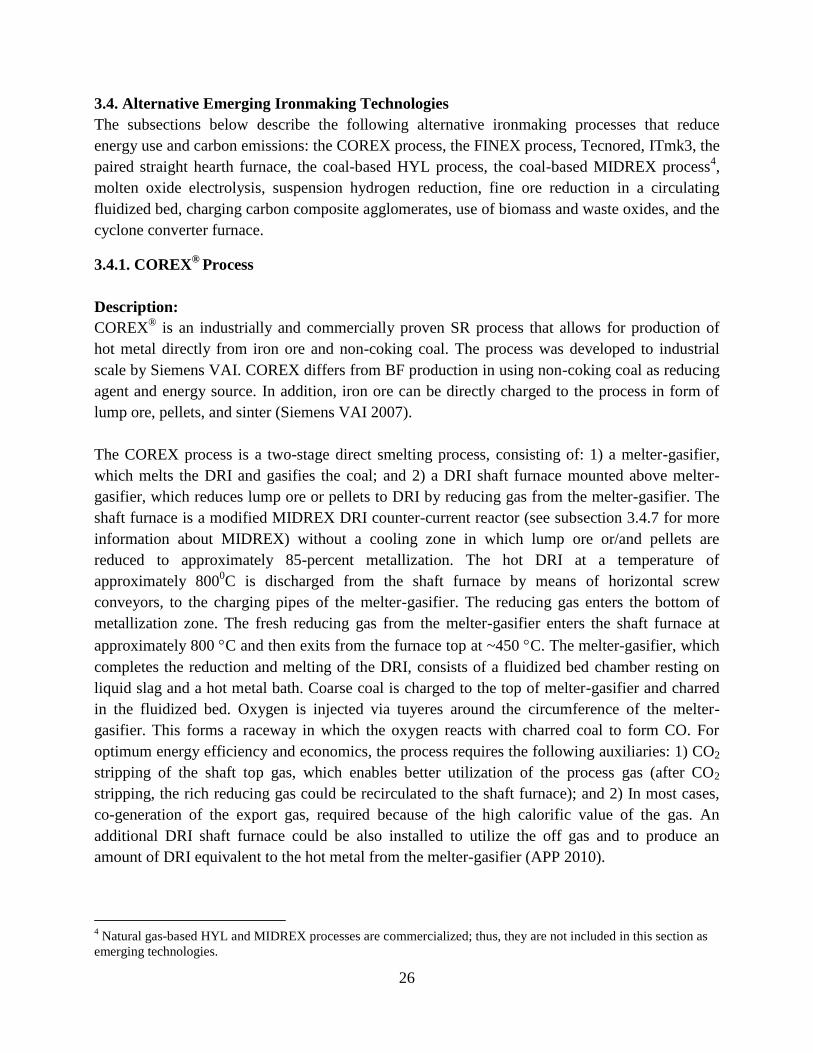
3.4. Alternative Emerging Ironmaking Technologies
The subsections below describe the following alternative ironmaking processes that reduce
energy use and carbon emissions: the COREX process, the FINEX process, Tecnored, ITmk3, the
paired straight hearth furnace, the coal-based HYL process, the coal-based MIDREX process4,
molten oxide electrolysis, suspension hydrogen reduction, fine ore reduction in a circulating
fluidized bed, charging carbon composite agglomerates, use of biomass and waste oxides, and the
cyclone converter furnace.
3.4.1. COREX®
Process
Description:
COREX® is an industrially and commercially proven SR process that allows for production of
hot metal directly from iron ore and non-coking coal. The process was developed to industrial
scale by Siemens VAI. COREX differs from BF production in using non-coking coal as reducing
agent and energy source. In addition, iron ore can be directly charged to the process in form of
lump ore, pellets, and sinter (Siemens VAI 2007).
The COREX process is a two-stage direct smelting process, consisting of: 1) a melter-gasifier,
which melts the DRI and gasifies the coal; and 2) a DRI shaft furnace mounted above melter-
gasifier, which reduces lump ore or pellets to DRI by reducing gas from the melter-gasifier. The
shaft furnace is a modified MIDREX DRI counter-current reactor (see subsection 3.4.7 for more
information about MIDREX) without a cooling zone in which lump ore or/and pellets are
reduced to approximately 85-percent metallization. The hot DRI at a temperature of
approximately 8000C is discharged from the shaft furnace by means of horizontal screw
conveyors, to the charging pipes of the melter-gasifier. The reducing gas enters the bottom of
metallization zone. The fresh reducing gas from the melter-gasifier enters the shaft furnace at
approximately 800 C and then exits from the furnace top at ~450 C. The melter-gasifier, which
completes the reduction and melting of the DRI, consists of a fluidized bed chamber resting on
liquid slag and a hot metal bath. Coarse coal is charged to the top of melter-gasifier and charred
in the fluidized bed. Oxygen is injected via tuyeres around the circumference of the melter-
gasifier. This forms a raceway in which the oxygen reacts with charred coal to form CO. For
optimum energy efficiency and economics, the process requires the following auxiliaries: 1) CO2
stripping of the shaft top gas, which enables better utilization of the process gas (after CO2
stripping, the rich reducing gas could be recirculated to the shaft furnace); and 2) In most cases,
co-generation of the export gas, required because of the high calorific value of the gas. An
additional DRI shaft furnace could be also installed to utilize the off gas and to produce an
amount of DRI equivalent to the hot metal from the melter-gasifier (APP 2010).
4 Natural gas-based HYL and MIDREX processes are commercialized; thus, they are not included in this section as
emerging technologies.
27
Some of the limitations of the COREX process are (Agrawal and Mathur 2011):
It can't use ore fines directly
There are restrictions on non-coking coal (volatile matter of carbonaceous material to be
maintained at around 25%
Net export gas should be utilised very economically, otherwise the process becomes un-
viable.
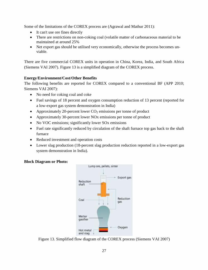
There are five commercial COREX units in operation in China, Korea, India, and South Africa
(Siemens VAI 2007). Figure 13 is a simplified diagram of the COREX process.
Energy/Environment/Cost/Other Benefits
The following benefits are reported for COREX compared to a conventional BF (APP 2010;
Siemens VAI 2007):
No need for coking coal and coke
Fuel savings of 18 percent and oxygen consumption reduction of 13 percent (reported for
a low-export gas system demonstration in India)
Approximately 20-percent lower CO2 emissions per tonne of product
Approximately 30-percent lower NOx emissions per tonne of product
No VOC emissions; significantly lower SOx emissions
Fuel rate significantly reduced by circulation of the shaft furnace top gas back to the shaft
furnace
Reduced investment and operation costs
Lower slag production (18-percent slag production reduction reported in a low-export gas
system demonstration in India).
Block Diagram or Photo:
Figure 13. Simplified flow diagram of the COREX process (Siemens VAI 2007)
28
Commercial status:
Commercial with very low adoption rate
References for further information:
Siemens VAI (2007), APP (2010)
3.4.2. FINEX®
process
Description:
The FINEX® smelting-reduction process, developed by Siemens VAI and the Korean steel
producer Posco, is based on the direct use of non-coking coal and fine ore. The major difference
between the COREX and FINEX processes is that the FINEX process can directly use sinter feed
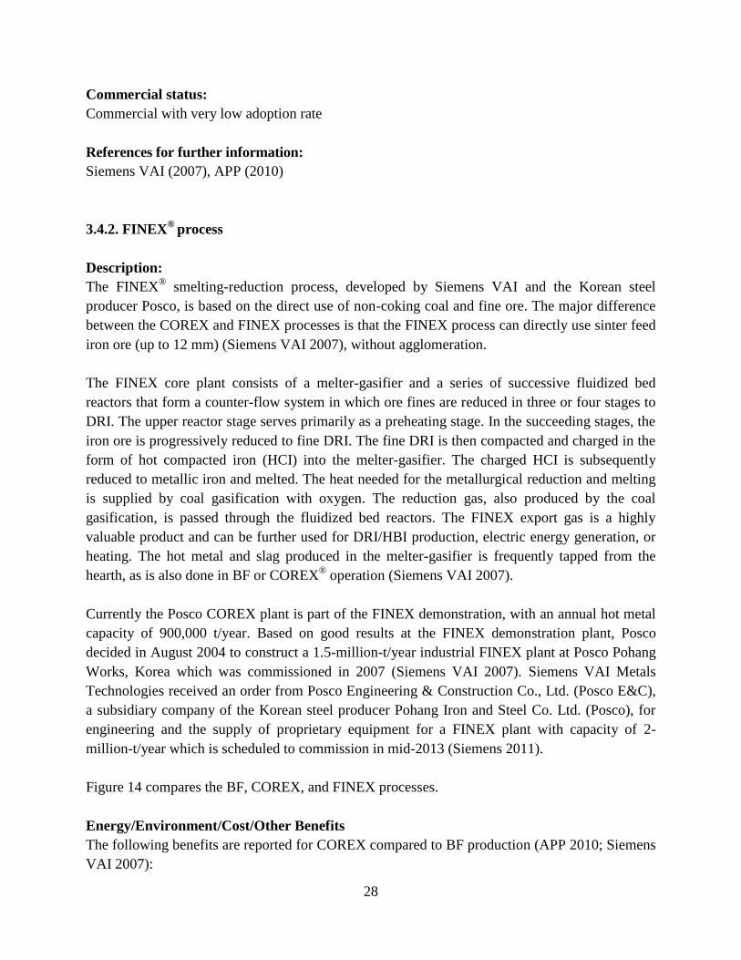
iron ore (up to 12 mm) (Siemens VAI 2007), without agglomeration.
The FINEX core plant consists of a melter-gasifier and a series of successive fluidized bed
reactors that form a counter-flow system in which ore fines are reduced in three or four stages to
DRI. The upper reactor stage serves primarily as a preheating stage. In the succeeding stages, the
iron ore is progressively reduced to fine DRI. The fine DRI is then compacted and charged in the
form of hot compacted iron (HCI) into the melter-gasifier. The charged HCI is subsequently
reduced to metallic iron and melted. The heat needed for the metallurgical reduction and melting
is supplied by coal gasification with oxygen. The reduction gas, also produced by the coal
gasification, is passed through the fluidized bed reactors. The FINEX export gas is a highly
valuable product and can be further used for DRI/HBI production, electric energy generation, or
heating. The hot metal and slag produced in the melter-gasifier is frequently tapped from the
hearth, as is also done in BF or COREX® operation (Siemens VAI 2007).
Currently the Posco COREX plant is part of the FINEX demonstration, with an annual hot metal
capacity of 900,000 t/year. Based on good results at the FINEX demonstration plant, Posco
decided in August 2004 to construct a 1.5-million-t/year industrial FINEX plant at Posco Pohang
Works, Korea which was commissioned in 2007 (Siemens VAI 2007). Siemens VAI Metals
Technologies received an order from Posco Engineering & Construction Co., Ltd. (Posco E&C),
a subsidiary company of the Korean steel producer Pohang Iron and Steel Co. Ltd. (Posco), for
engineering and the supply of proprietary equipment for a FINEX plant with capacity of 2-
million-t/year which is scheduled to commission in mid-2013 (Siemens 2011).
Figure 14 compares the BF, COREX, and FINEX processes.
Energy/Environment/Cost/Other Benefits
The following benefits are reported for COREX compared to BF production (APP 2010; Siemens
VAI 2007):
29
No need for pelletizing, sintering, or agglomeration of iron-bearing materials
Allows use of fine concentrates
Capital cost claimed to be 20 percent lower than for BF, and production cost 15 percent
lower
Lower emissions because of lower energy consumption and no need for coke making
Direct utilization of non-coking coal
High valuable export gas for a wide range of applications in metallurgical processes and
energy production
Production of hot metal with quality similar to that produced in a BF
Block Diagram or Photo:
Note: This figure is primarily for illustration of major differences between three process. For the case of BF, however, in addition
to sinter than is shown, the lump iron ore or sinter (or combinations) can be charged in BF.
Figure 14. Comparison of BF, COREX, and FINEX processes (Grill 2009)
Commercial status:
Commercial with very low adoption rate
References for further information:
Siemens VAI (2007), APP (2010)
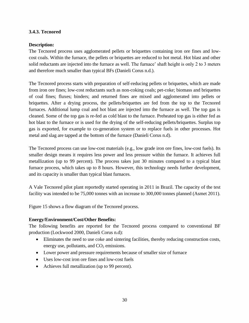
30
3.4.3. Tecnored
Description:
The Tecnored process uses agglomerated pellets or briquettes containing iron ore fines and low-
cost coals. Within the furnace, the pellets or briquettes are reduced to hot metal. Hot blast and other
solid reductants are injected into the furnace as well. The furnace’ shaft height is only to 3 meters
and therefore much smaller than typical BFs (Danieli Corus n.d.).
The Tecnored process starts with preparation of self-reducing pellets or briquettes, which are made
from iron ore fines; low-cost reductants such as non-coking coals; pet-coke; biomass and briquettes
of coal fines; fluxes; binders; and returned fines are mixed and agglomerated into pellets or
briquettes. After a drying process, the pellets/briquettes are fed from the top to the Tecnored
furnaces. Additional lump coal and hot blast are injected into the furnace as well. The top gas is
cleaned. Some of the top gas is re-fed as cold blast to the furnace. Preheated top gas is either fed as
hot blast to the furnace or is used for the drying of the self-reducing pellets/briquettes. Surplus top
gas is exported, for example to co-generation system or to replace fuels in other processes. Hot
metal and slag are tapped at the bottom of the furnace (Danieli Corus n.d).
The Tecnored process can use low-cost materials (e.g., low grade iron ore fines, low-cost fuels). Its
smaller design means it requires less power and less pressure within the furnace. It achieves full
metallization (up to 99 percent). The process takes just 30 minutes compared to a typical blast
furnace process, which takes up to 8 hours. However, this technology needs further development,
and its capacity is smaller than typical blast furnaces.
A Vale Tecnored pilot plant reportedly started operating in 2011 in Brazil. The capacity of the test
facility was intended to be 75,000 tonnes with an increase to 300,000 tonnes planned (Asmet 2011).
Figure 15 shows a flow diagram of the Tecnored process.
Energy/Environment/Cost/Other Benefits:
The following benefits are reported for the Tecnored process compared to conventional BF
production (Lockwood 2000, Danieli Corus n.d):
Eliminates the need to use coke and sintering facilities, thereby reducing construction costs,
energy use, pollutants, and CO2 emissions.
Lower power and pressure requirements because of smaller size of furnace
Uses low-cost iron ore fines and low-cost fuels
Achieves full metallization (up to 99 percent).
31
Block Diagram or Photo:
Figure 15. Flow diagram of the Tecnored process (Lockwood 2000)
Commercial Status:
Pilot stage
References for further information:
Lockwood (2000), Danieli Corus (n.d), Asmet (2011), Júniora et al. (2005)
3.4.4. ITmk3® Ironmaking Process
Description:
In almost all direct reduction ironmaking technologies that use a rotary hearth furnace (RHF), the
RHF reduces iron ore to about 80 percent. A secondary smelting facility removes the remaining
other material (gangue) from the ore. The DRI produced is usually taken to an EAF for final
reduction and gangue removal. However, ITmk3® technology uses the RHF as a stand-alone unit
that produces gangue-free metal eliminating the need for a secondary smelting process (Fruehan
2004a). The ITmk3 process uses low-grade iron ore5 and coal (other feedstocks can be used as
5 This process does not use low grade ore directly. Low grade ores are beneficiated, and the resulting fines (with >62%
Fe content) are pelletized and used.
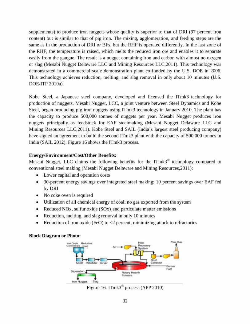
32
supplements) to produce iron nuggets whose quality is superior to that of DRI (97 percent iron
content) but is similar to that of pig iron. The mixing, agglomeration, and feeding steps are the
same as in the production of DRI or BFs, but the RHF is operated differently. In the last zone of
the RHF, the temperature is raised, which melts the reduced iron ore and enables it to separate
easily from the gangue. The result is a nugget containing iron and carbon with almost no oxygen
or slag (Mesabi Nugget Delaware LLC and Mining Resources LLC,2011). This technology was
demonstrated in a commercial scale demonstration plant co-funded by the U.S. DOE in 2006.
This technology achieves reduction, melting, and slag removal in only about 10 minutes (U.S.
DOE/ITP 2010a).
Kobe Steel, a Japanese steel company, developed and licensed the ITmk3 technology for
production of nuggets. Mesabi Nugget, LCC, a joint venture between Steel Dynamics and Kobe
Steel, began producing pig iron nuggets using ITmk3 technology in January 2010. The plant has
the capacity to produce 500,000 tonnes of nuggets per year. Mesabi Nugget produces iron
nuggets principally as feedstock for EAF steelmaking (Mesabi Nugget Delaware LLC and
Mining Resources LLC,2011). Kobe Steel and SAIL (India’s largest steel producing company)
have signed an agreement to build the second ITmk3 plant with the capacity of 500,000 tonnes in
India (SAIL 2012). Figure 16 shows the ITmk3 process.
Energy/Environment/Cost/Other Benefits:
Mesabi Nugget, LLC claims the following benefits for the ITmk3® technology compared to
conventional steel making (Mesabi Nugget Delaware and Mining Resources,2011):
Lower capital and operation costs
30-percent energy savings over integrated steel making; 10 percent savings over EAF fed
by DRI
No coke oven is required
Utilization of all chemical energy of coal; no gas exported from the system
Reduced NOx, sulfur oxide (SOx), and particulate matter emissions
Reduction, melting, and slag removal in only 10 minutes
Reduction of iron oxide (FeO) to <2 percent, minimizing attack to refractories
Block Diagram or Photo:
Figure 16. ITmk3® process (APP 2010)
33
Commercial Status:
Demonestration stage
Reference for further information:
Mesabi Nugget Delaware and Mining Resources (2011); Fruehan (2004a)
3.4.5. Paired Straight Hearth Furnace
Description:
The paired straight hearth (PSH) furnace is charged with cold-bonded self-reducing pellets
composed of iron oxide and coal. When the pellets are heated, the iron oxide is chemically
reduced to produce a 95-percent metallized pellet suitable for use in steelmaking in an EAF. The
sources of the iron oxide can be iron ore fines, recycled steel plant wastes, or a combination of
the two. The reductant is high-volatility coal. As the pellets are heated on the hearth, CO gas is
evolved and combusted above the pellet bed to drive the process. The bed of conventional RHFs
is only two to three pellets high whereas the PSH furnace has a bed height of eight pellets
(approximately 120 mm). The PSH furnace off gases are fully combusted to raise the temperature
above the bed to 1,600ºC. Reoxidation is prevented by the CO-rich gases rising through the bed.
The PSH furnace technology is significantly more productive while using less energy than
conventional furnaces (AISI 2010). The initial research program, funded by the DOE/AISI TR
Program, was completed in 2002.
In 2006, DOE/AISI, through its TR Program, commissioned an engineering study by a well-
known furnace builder to verify the feasibility and costs of building a PSH furnace. The study
concluded that it is feasible to design, build, and continuously operate a PSH furnace to produce
46,000 t per year of DRI at 95-percent metallization for a cost of $16,729,000. A detailed design
and validation study to evaluate raw material flexibility was then initiated, and this study is
scheduled to be completed in 2013. A demonstration-scale PSH furnace planned after that study
is complete. The PSH furnace may be coupled to a smelter to provide a viable replacement for
BF and BOF steelmaking.
Technology integration issues related to materials handling, furnace and waste treatment control
systems, pellet quality, multi-layer bed stability, DRI quality, material throughput, process
economics, long-term furnace performance, reliability, and stability are some of the barriers and
uncertainties about this technology that need to be addressed (U.S. DOE/ITP 2011a).
The most likely point of initial entry for PSH furnaces into the mainstream market is integrated
steelmaking facilities that might be looking for an alternative source of hot metal. This could
include producers of coil, slab, long, or specialty steel products (U.S. DOE/ITP 2011a).
Figure 17 shows the process flow in a PSH furnace.
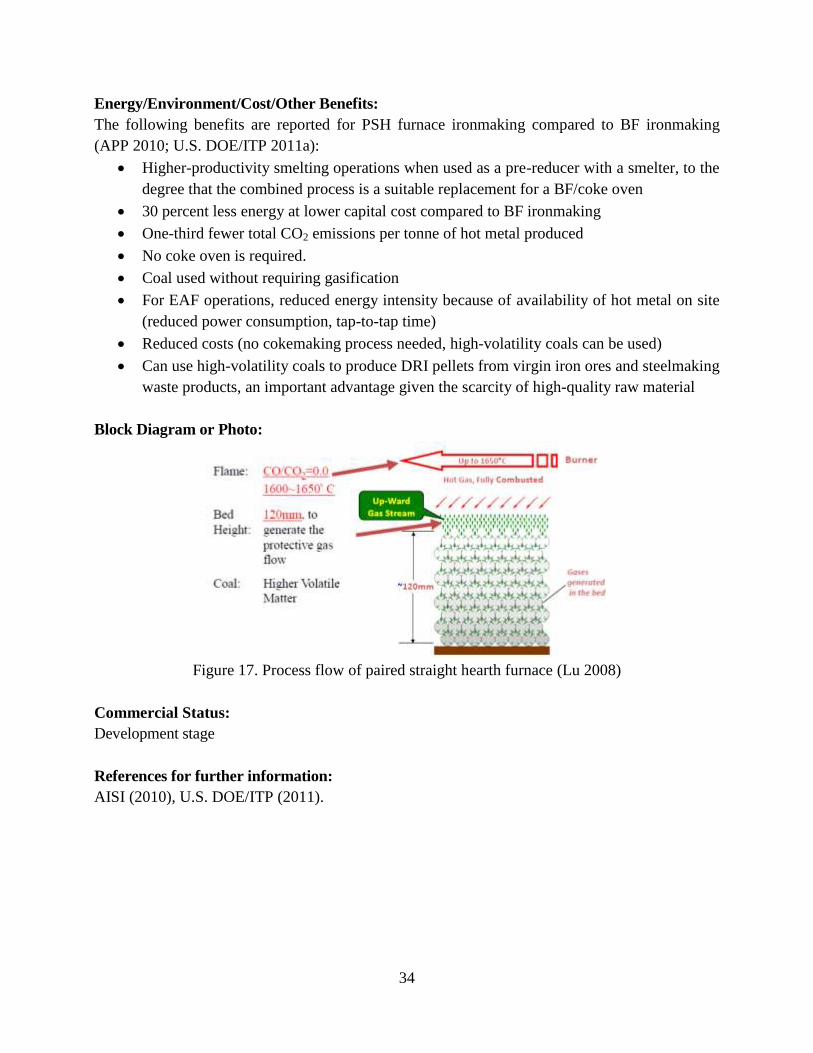
34
Energy/Environment/Cost/Other Benefits:
The following benefits are reported for PSH furnace ironmaking compared to BF ironmaking
(APP 2010; U.S. DOE/ITP 2011a):
Higher-productivity smelting operations when used as a pre-reducer with a smelter, to the
degree that the combined process is a suitable replacement for a BF/coke oven
30 percent less energy at lower capital cost compared to BF ironmaking
One-third fewer total CO2 emissions per tonne of hot metal produced
No coke oven is required.
Coal used without requiring gasification
For EAF operations, reduced energy intensity because of availability of hot metal on site
(reduced power consumption, tap-to-tap time)
Reduced costs (no cokemaking process needed, high-volatility coals can be used)
Can use high-volatility coals to produce DRI pellets from virgin iron ores and steelmaking
waste products, an important advantage given the scarcity of high-quality raw material
Block Diagram or Photo:
Figure 17. Process flow of paired straight hearth furnace (Lu 2008)
Commercial Status:
Development stage
References for further information:
AISI (2010), U.S. DOE/ITP (2011).
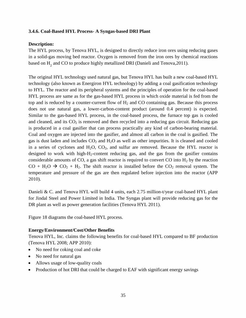
35
3.4.6. Coal-Based HYL Process- A Syngas-based DRI Plant
Description:
The HYL process, by Tenova HYL, is designed to directly reduce iron ores using reducing gases
in a solid-gas moving bed reactor. Oxygen is removed from the iron ores by chemical reactions
based on H2 and CO to produce highly metallized DRI (Danieli and Tenova,2011).
The original HYL technology used natural gas, but Tenova HYL has built a new coal-based HYL
technology (also known as Energiron HYL technology) by adding a coal gasification technology
to HYL. The reactor and its peripheral systems and the principles of operation for the coal-based
HYL process are same as for the gas-based HYL process in which oxide material is fed from the
top and is reduced by a counter-current flow of H2 and CO containing gas. Because this process
does not use natural gas, a lower-carbon-content product (around 0.4 percent) is expected.
Similar to the gas-based HYL process, in the coal-based process, the furnace top gas is cooled
and cleaned, and its CO2 is removed and then recycled into a reducing gas circuit. Reducing gas
is produced in a coal gasifier that can process practically any kind of carbon-bearing material.
Coal and oxygen are injected into the gasifier, and almost all carbon in the coal is gasified. The
gas is dust laden and includes CO2 and H2O as well as other impurities. It is cleaned and cooled
in a series of cyclones and H2O, CO2, and sulfur are removed. Because the HYL reactor is
designed to work with high-H2-content reducing gas, and the gas from the gasifier contains
considerable amounts of CO, a gas shift reactor is required to convert CO into H2 by the reaction
CO + H2O CO2 + H2. The shift reactor is installed before the CO2 removal system. The
temperature and pressure of the gas are then regulated before injection into the reactor (APP
2010).
Danieli & C. and Tenova HYL will build 4 units, each 2.75 million-t/year coal-based HYL plant
for Jindal Steel and Power Limited in India. The Syngas plant will provide reducing gas for the
DR plant as well as power generation facilities (Tenova HYL 2011).
Figure 18 diagrams the coal-based HYL process.
Energy/Environment/Cost/Other Benefits
Tenova HYL, Inc. claims the following benefits for coal-based HYL compared to BF production
(Tenova HYL 2008; APP 2010):
No need for coking coal and coke
No need for natural gas
Allows usage of low-quality coals
Production of hot DRI that could be charged to EAF with significant energy savings
36
Block Diagram or Photo:
Figure 18. Coal-Based HYL Process (Tenova HYL 2008)
Commercial status:
Commercial with very low adoption rate
References for further information:
Tenova HYL (2008), APP (2010)
3.4.7. Coal-Based MIDREX® Process
Description:
The MIDREX® direct reduction process uses a natural-gas-based shaft furnace process that
converts iron oxides (pellets or lump ore) into DRI. The MIDREX direct reduction technology
has evolved during the past four decades from plant capacities of just 150,000 t/year to capacities
now approaching 2 million t/year (Siemens VAI 2007). This process currently produces 60
percent of the world’s DRI annually (MIDREX Technologies, Inc. 2012). However, because not
all regions have abundant, inexpensive natural gas, another direct reduction alternative is needed.
An alternative option is the MXCOL process, which uses synthetic gas (syngas) made from coal
in combination with a MIDREX® direct reduction plant. Syngas options include a coal gasifier,
coke oven gas, or BOF gas. The big advantage of coal gasification is that lower-grade,
inexpensive domestic coals can be used to produce a high-quality reducing gas for the MIDREX
shaft furnace (MIDREX Technologies, Inc.2011).
The coal-based MXCOL/MIDREX reactor and auxiliary systems are the same as those for a gas-
based MIDREX plant. In the MXCOL process, the cold syngas is depressurized to about 3 bar in
a turbo expander, which generates electricity. The low-pressure syngas is mixed with recycled
37
gas to produce the required reducing gas. The mixed gas is then heated to more than 9,00ºC and
enters the shaft furnace where it reacts with the iron oxide to produce DRI. The spent reducing
gas (top gas) exiting the shaft furnace is scrubbed and cooled, then passed through a CO2 removal
system, which reduces the CO2 content to 2-3 percent or less. This ensures that the mixed
reducing gas (syngas from the gasification plant and recycled top gas from the MIDREX plant)
has an acceptably high reductant (H2+CO) to oxidant (H2O+ CO2) ratio for efficient iron oxide
reduction. The CO2 removal system will also remove the sulfur gases contained in the recycled
top gas. The recycling of the top gas makes MXCOL a very efficient process. Very pure CO2 is
recovered from the gasifier cleaning and conditioning plant and the CO2 removal system in the
MIDREX plant. These streams could be sequestered or sold for enhanced oil recovery or use in a
petrochemical or other operation (MIDREX Technologies, Inc.2011).
Jindal Steel and Power Limited in India has contracted with MIDREX Technologies for a 1.8
Mt/year MXCOL plant, the world’s first coal gasifier-based MIDREX plant (MIDREX
Technologies, Inc.2011).
Figure 19 shows a diagram of the coal-based MIDREX process.
Energy/Environment/Cost/Other Benefits
MIDREX Technologies, Inc. claims the ffollowing benefits for coal-based MIDREX compared to
BF production (MIDREX Technologies, Inc.2011):
Can use any coal gasification technology (The additional cost of coal gasification should
be taken into account.)
Fixed-bed or fluidized-bed gasifiers able to readily use the low-rank, high-ash domestic
coals in India and China
Potential to use coal syngas from other sources such as coke oven gas or BOF gas
Uses the well-proven MIDREX direct reduction process; can readily use domestic iron
oxides as feed material.
Produces DRI with quality comparable to that produced by natural gas-based MIDREX
plants
The DRI can be hot charged into a nearby EAF to significantly reduce the EAF electricity
requirement and increase productivity
No coke, coke ovens, or sinter plant required
Lower specific capital cost than an integrated steel works
Lower air emissions than an integrated steel works
Ability to capture high-purity CO2 for sequestering or injecting into oil and gas fields
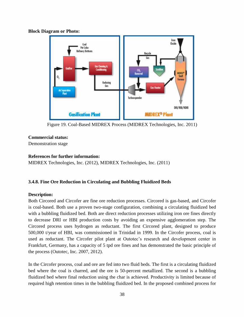
38
Block Diagram or Photo:
Figure 19. Coal-Based MIDREX Process (MIDREX Technologies, Inc. 2011)
Commercial status:
Demonstration stage
References for further information:
MIDREX Technologies, Inc. (2012), MIDREX Technologies, Inc. (2011)
3.4.8. Fine Ore Reduction in Circulating and Bubbling Fluidized Beds
Description:
Both Circored and Circofer are fine ore reduction processes. Circored is gas-based, and Circofer
is coal-based. Both use a proven two-stage configuration, combining a circulating fluidized bed
with a bubbling fluidized bed. Both are direct reduction processes utilizing iron ore fines directly
to decrease DRI or HBI production costs by avoiding an expensive agglomeration step. The
Circored process uses hydrogen as reductant. The first Circored plant, designed to produce
500,000 t/year of HBI, was commissioned in Trinidad in 1999. In the Circofer process, coal is
used as reductant. The Circofer pilot plant at Outotec’s research and development center in
Frankfurt, Germany, has a capacity of 5 tpd ore fines and has demonstrated the basic principle of
the process (Outotec, Inc. 2007, 2012).
In the Circofer process, coal and ore are fed into two fluid beds. The first is a circulating fluidized
bed where the coal is charred, and the ore is 50-percent metallized. The second is a bubbling
fluidized bed where final reduction using the char is achieved. Productivity is limited because of
required high retention times in the bubbling fluidized bed. In the proposed combined process for
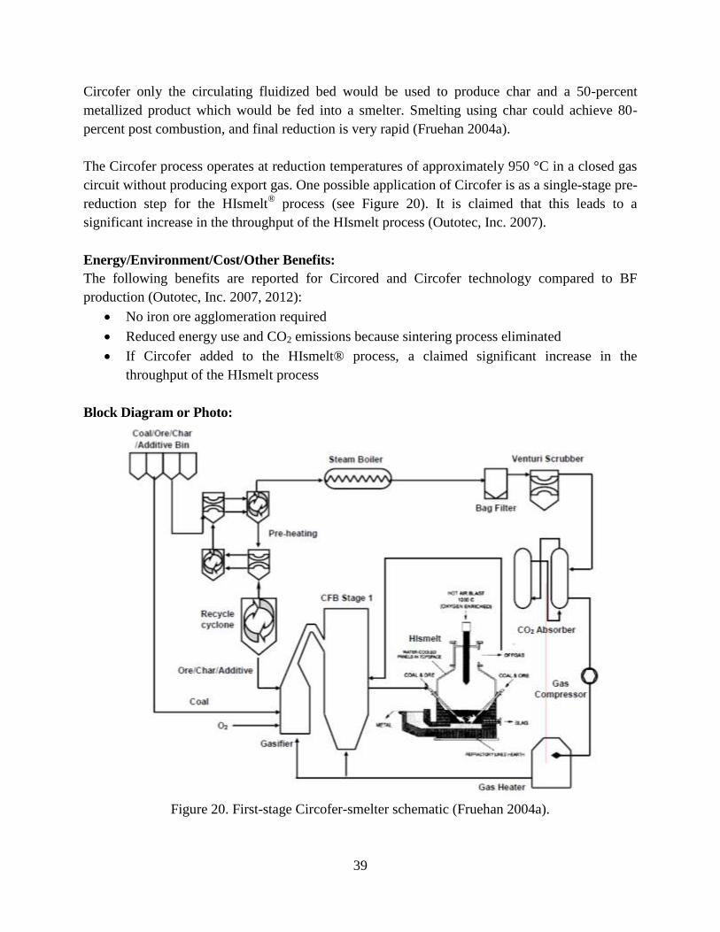
39
Circofer only the circulating fluidized bed would be used to produce char and a 50-percent
metallized product which would be fed into a smelter. Smelting using char could achieve 80-
percent post combustion, and final reduction is very rapid (Fruehan 2004a).
The Circofer process operates at reduction temperatures of approximately 950 °C in a closed gas
circuit without producing export gas. One possible application of Circofer is as a single-stage pre-
reduction step for the HIsmelt® process (see Figure 20). It is claimed that this leads to a
significant increase in the throughput of the HIsmelt process (Outotec, Inc. 2007).
Energy/Environment/Cost/Other Benefits:
The following benefits are reported for Circored and Circofer technology compared to BF
production (Outotec, Inc. 2007, 2012):
No iron ore agglomeration required
Reduced energy use and CO2 emissions because sintering process eliminated
If Circofer added to the HIsmelt® process, a claimed significant increase in the
throughput of the HIsmelt process
Block Diagram or Photo:
Figure 20. First-stage Circofer-smelter schematic (Fruehan 2004a).
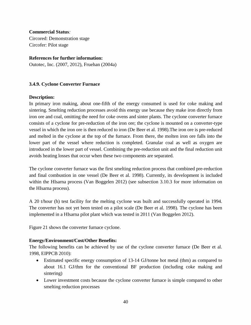
40
Commercial Status:
Circored: Demonstration stage
Circofer: Pilot stage
References for further information:
Outotec, Inc. (2007, 2012), Fruehan (2004a)
3.4.9. Cyclone Converter Furnace
Description:
In primary iron making, about one-fifth of the energy consumed is used for coke making and
sintering. Smelting reduction processes avoid this energy use because they make iron directly from
iron ore and coal, omitting the need for coke ovens and sinter plants. The cyclone converter furnace
consists of a cyclone for pre-reduction of the iron ore; the cyclone is mounted on a converter-type
vessel in which the iron ore is then reduced to iron (De Beer et al. 1998).The iron ore is pre-reduced
and melted in the cyclone at the top of the furnace. From there, the molten iron ore falls into the
lower part of the vessel where reduction is completed. Granular coal as well as oxygen are
introduced in the lower part of vessel. Combining the pre-reduction unit and the final reduction unit
avoids heating losses that occur when these two components are separated.
The cyclone converter furnace was the first smelting reduction process that combined pre-reduction
and final combustion in one vessel (De Beer et al. 1998). Currently, its development is included
within the HIsarna process (Van Boggelen 2012) (see subsection 3.10.3 for more information on
the HIsarna process).
A 20 t/hour (h) test facility for the melting cyclone was built and successfully operated in 1994.
The converter has not yet been tested on a pilot scale (De Beer et al. 1998). The cyclone has been
implemented in a HIsarna pilot plant which was tested in 2011 (Van Boggelen 2012).
Figure 21 shows the converter furnace cyclone.
Energy/Environment/Cost/Other Benefits:
The following benefits can be achieved by use of the cyclone converter furnace (De Beer et al.
1998, EIPPCB 2010):
Estimated specific energy consumption of 13-14 GJ/tonne hot metal (thm) as compared to
about 16.1 GJ/thm for the conventional BF production (including coke making and
sintering)
Lower investment costs because the cyclone converter furnace is simple compared to other
smelting reduction processes
41
Total production costs estimated to be lower than those of BF
Block Diagram or Photo:
Figure 21. Converter furnace cyclone (CCF) (Van Boggelen 2012)
Commercial Status:
Pilot stage
References for further information:
Van Boggelen (2012), De Beer et al. (1998), EIPPCB (2010)
3.4.10. Producing Iron by Electrolysis of Iron Ore (Molten Oxide Electrolysis)
Description:
Electrolysis of iron ore or molten oxide electrolysis (MOE) is an emerging process. The DOE/
AISI TR program funded an initial R&D project at MIT (Cambridge, MA USA) which was
successfully completed in 2007. A similar technology is currently being studied in the ULCOS
program. This process would allow the transformation of iron ore into metal and gaseous oxygen
(O2) using only electrical energy. Producing iron by electrolysis would eliminate the need for
coke ovens and the reactors used for reducing the iron ore, such as BFs, and thereby eliminate the
CO2 created by these production methods. Although no iron is currently produced industrially by
electrolysis, electrolysis is a well-established technique developed at the industrial scale for
production of aluminum, zinc, and nickel (ULCOS 2012a).
MOE is an extreme form of molten salt electrolysis, a technology that has been used to produce
tonnage metal – aluminum, magnesium, lithium, sodium, and the rare-earth metals – for more
than 100 years. MOE is different from other molten salt electrolytic technologies because it uses
carbon-free anodes, which facilitates the production of oxygen gas at the anode. MOE is totally
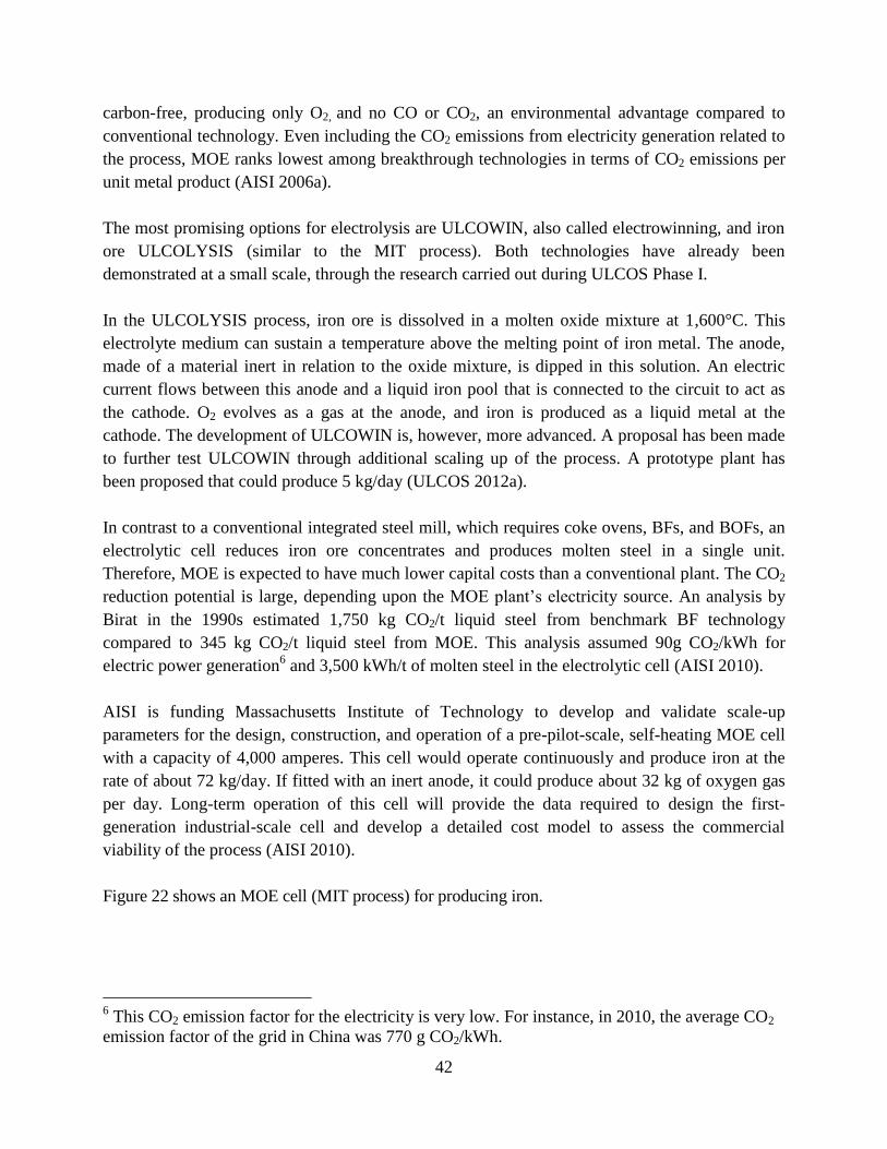
42
carbon-free, producing only O2, and no CO or CO2, an environmental advantage compared to
conventional technology. Even including the CO2 emissions from electricity generation related to
the process, MOE ranks lowest among breakthrough technologies in terms of CO2 emissions per
unit metal product (AISI 2006a).
The most promising options for electrolysis are ULCOWIN, also called electrowinning, and iron
ore ULCOLYSIS (similar to the MIT process). Both technologies have already been
demonstrated at a small scale, through the research carried out during ULCOS Phase I.
In the ULCOLYSIS process, iron ore is dissolved in a molten oxide mixture at 1,600°C. This
electrolyte medium can sustain a temperature above the melting point of iron metal. The anode,
made of a material inert in relation to the oxide mixture, is dipped in this solution. An electric
current flows between this anode and a liquid iron pool that is connected to the circuit to act as
the cathode. O2 evolves as a gas at the anode, and iron is produced as a liquid metal at the
cathode. The development of ULCOWIN is, however, more advanced. A proposal has been made
to further test ULCOWIN through additional scaling up of the process. A prototype plant has
been proposed that could produce 5 kg/day (ULCOS 2012a).
In contrast to a conventional integrated steel mill, which requires coke ovens, BFs, and BOFs, an
electrolytic cell reduces iron ore concentrates and produces molten steel in a single unit.
Therefore, MOE is expected to have much lower capital costs than a conventional plant. The CO2
reduction potential is large, depending upon the MOE plant’s electricity source. An analysis by
Birat in the 1990s estimated 1,750 kg CO2/t liquid steel from benchmark BF technology
compared to 345 kg CO2/t liquid steel from MOE. This analysis assumed 90g CO2/kWh for
electric power generation6 and 3,500 kWh/t of molten steel in the electrolytic cell (AISI 2010).
AISI is funding Massachusetts Institute of Technology to develop and validate scale-up
parameters for the design, construction, and operation of a pre-pilot-scale, self-heating MOE cell
with a capacity of 4,000 amperes. This cell would operate continuously and produce iron at the
rate of about 72 kg/day. If fitted with an inert anode, it could produce about 32 kg of oxygen gas
per day. Long-term operation of this cell will provide the data required to design the first-
generation industrial-scale cell and develop a detailed cost model to assess the commercial
viability of the process (AISI 2010).
Figure 22 shows an MOE cell (MIT process) for producing iron.
6 This CO2 emission factor for the electricity is very low. For instance, in 2010, the average CO2
emission factor of the grid in China was 770 g CO2/kWh.
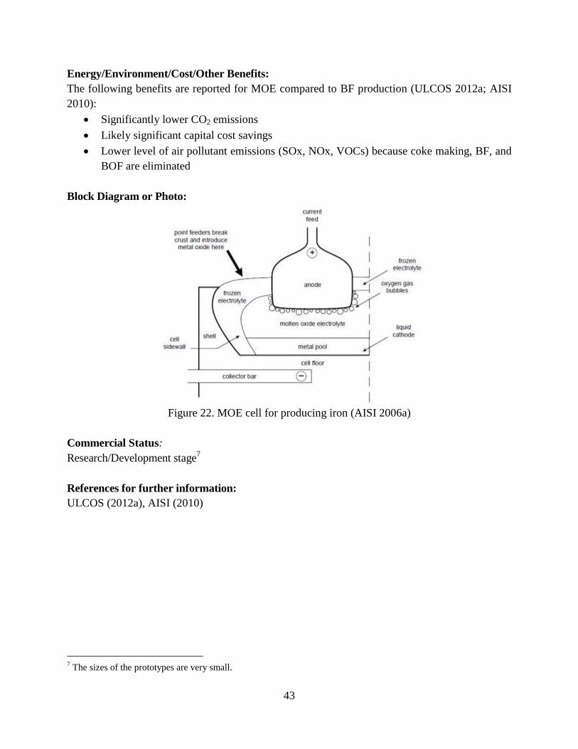
43
Energy/Environment/Cost/Other Benefits:
The following benefits are reported for MOE compared to BF production (ULCOS 2012a; AISI
2010):
Significantly lower CO2 emissions
Likely significant capital cost savings
Lower level of air pollutant emissions (SOx, NOx, VOCs) because coke making, BF, and
BOF are eliminated
Block Diagram or Photo:
Figure 22. MOE cell for producing iron (AISI 2006a)
Commercial Status:
Research/Development stage7
References for further information:
ULCOS (2012a), AISI (2010)
7 The sizes of the prototypes are very small.
44
3.4.11. Suspension Hydrogen (or H2 containing Gaseous mixtures) Reduction of Iron Oxide
Concentrate
Description:
Hydrogen is currently cost prohibitive as a reducing agent or fuel. Large quantities of inexpensive
hydrogen may become available in the future based on worldwide R&D work. Hydrogen
produces only water vapor and no other gaseous byproducts when used as a reducing agent or
fuel (AISI 2006b).
Hydrogen flash smelting would use, as a smelting vessel, a suspension or flash-type furnace
similar to those used in the copper industry. Iron ore concentrates would be sprayed directly into
the furnace chamber. Three reductants are suitable for this type of vessel: H2, natural gas, or
synthetic gas produced from partial combustion of coal and/or waste plastics. The high
temperature and lack of contact between the iron ore particles in suspension furnaces eliminates
sticking and fusion of the particles (AISI 2010).
Detailed material and energy balances conducted by University of Utah in an earlier R&D project
with the support of the DOE/AISI TR Program show that the proposed technology using any of
the three possible reductants/fuels could use approximately 38 percent less energy than a BF.
This savings results largely from eliminating coke making and the iron ore pelletizing and
sintering steps. If hydrogen is used, this new technology will generate only 4 percent of the CO2
produced in the BF process; when natural gas or coal is used, CO2 emissions are 39 percent and
69 percent, respectively, of those from a BF. Because the residence time in a suspension furnace
is only a few seconds, studies were performed to establish that full reduction could be achieved in
such a short time. Kinetic studies of the reduction of iron oxide concentrates (~30 micrometer
size) as a function of temperature and gas composition showed that 90- to 99-percent reduction is
possible within a few seconds at temperatures of 1,300°C or higher. This was verified by larger
bench-scale testing, proving that complete ore reduction is achieved in the residence time typical
of industrial-size suspension vessels (AISI 2010).
Conventional BF-based steelmaking processes use CO gas to remove oxygen in iron ore.
However, the molecules of CO gas are large enough that it is difficult for them to penetrate iron
ore. By contrast, the much smaller molecules of H2 gas can easily penetrate into iron ore. The
penetration rate of H2 into iron is five times as great as that of CO, so H2 can rapidly reduce iron
ore in a conventional BF (JISF 2012b).
Hydrogen reduction could be a part of an overall continuous direct steelmaking process, in which
case the product from this process would be collected in its molten or solid state (e.g., reduced
iron pellets or briquettes) (AISI 2006b).
45
Based on the success of the earlier project conducted by University of Utah, AISI had initiated a
subsequent Phase II-project where a larger-scale bench reactor vessel was fabricated (AISI 2010).
In 2012, a $7.1 million award was given by the U.S. DOE to AISI/University of Utah to perform
tests to determine the best vessel configuration and reductant to be used in a future industrial pilot
plant8.
Figure 23 is a diagram of hydrogen flash smelting.
Energy/Environment/Cost/Other Benefits:
The following benefits are reported for hydrogen flash smelting compared to BF production
(AISI 2010):
Reduction or elimination of CO2 generation in the ironmaking process
Reduction in energy consumption; University of Utah earlier R&D study showed
potential energy savings of 7.4 GJ/t hot metal (more than 50 percent of conventional BF
energy use)
Reduction of iron oxide waste
Block Diagram or Photo:
Figure 23. Hydrogen flash smelting for copper (AISI 2010)
Commercial Status:
Research/Development stage9
References for further information:
AISI (2010), JISF (2012b)
8 Personal communication, Debo Aichbhaumik and Keith Jamison of Energetics, Inc. October 2012.
9 The sizes of the prototypes are very small.
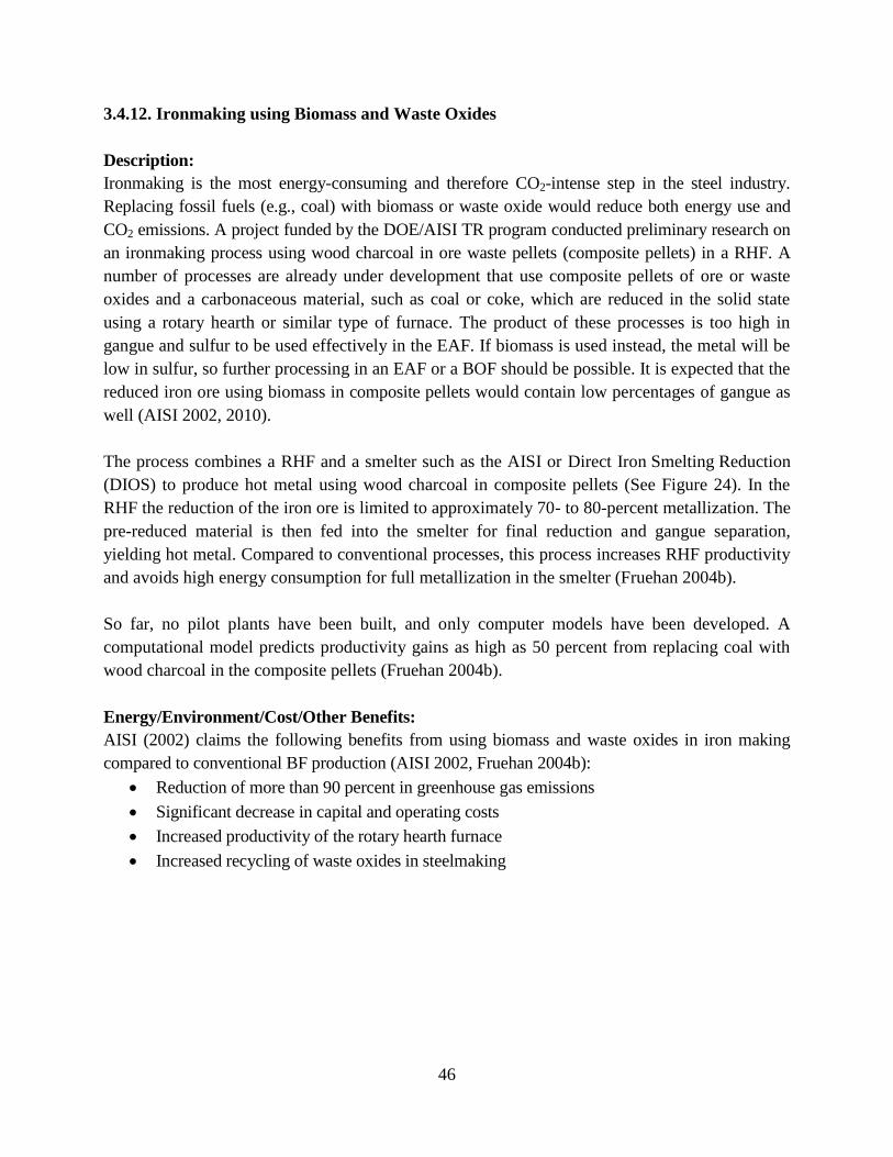
46
3.4.12. Ironmaking using Biomass and Waste Oxides
Description:
Ironmaking is the most energy-consuming and therefore CO2-intense step in the steel industry.
Replacing fossil fuels (e.g., coal) with biomass or waste oxide would reduce both energy use and
CO2 emissions. A project funded by the DOE/AISI TR program conducted preliminary research on
an ironmaking process using wood charcoal in ore waste pellets (composite pellets) in a RHF. A
number of processes are already under development that use composite pellets of ore or waste
oxides and a carbonaceous material, such as coal or coke, which are reduced in the solid state
using a rotary hearth or similar type of furnace. The product of these processes is too high in
gangue and sulfur to be used effectively in the EAF. If biomass is used instead, the metal will be
low in sulfur, so further processing in an EAF or a BOF should be possible. It is expected that the
reduced iron ore using biomass in composite pellets would contain low percentages of gangue as
well (AISI 2002, 2010).
The process combines a RHF and a smelter such as the AISI or Direct Iron Smelting Reduction
(DIOS) to produce hot metal using wood charcoal in composite pellets (See Figure 24). In the
RHF the reduction of the iron ore is limited to approximately 70- to 80-percent metallization. The
pre-reduced material is then fed into the smelter for final reduction and gangue separation,
yielding hot metal. Compared to conventional processes, this process increases RHF productivity
and avoids high energy consumption for full metallization in the smelter (Fruehan 2004b).
So far, no pilot plants have been built, and only computer models have been developed. A
computational model predicts productivity gains as high as 50 percent from replacing coal with
wood charcoal in the composite pellets (Fruehan 2004b).
Energy/Environment/Cost/Other Benefits:
AISI (2002) claims the following benefits from using biomass and waste oxides in iron making
compared to conventional BF production (AISI 2002, Fruehan 2004b):
Reduction of more than 90 percent in greenhouse gas emissions
Significant decrease in capital and operating costs
Increased productivity of the rotary hearth furnace
Increased recycling of waste oxides in steelmaking
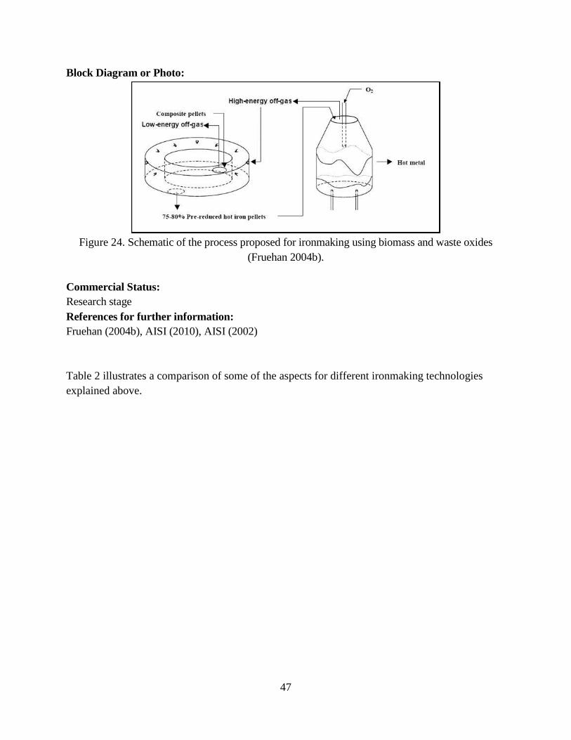
47
Block Diagram or Photo:
Figure 24. Schematic of the process proposed for ironmaking using biomass and waste oxides
(Fruehan 2004b).
Commercial Status:
Research stage
References for further information:
Fruehan (2004b), AISI (2010), AISI (2002)
Table 2 illustrates a comparison of some of the aspects for different ironmaking technologies
explained above.
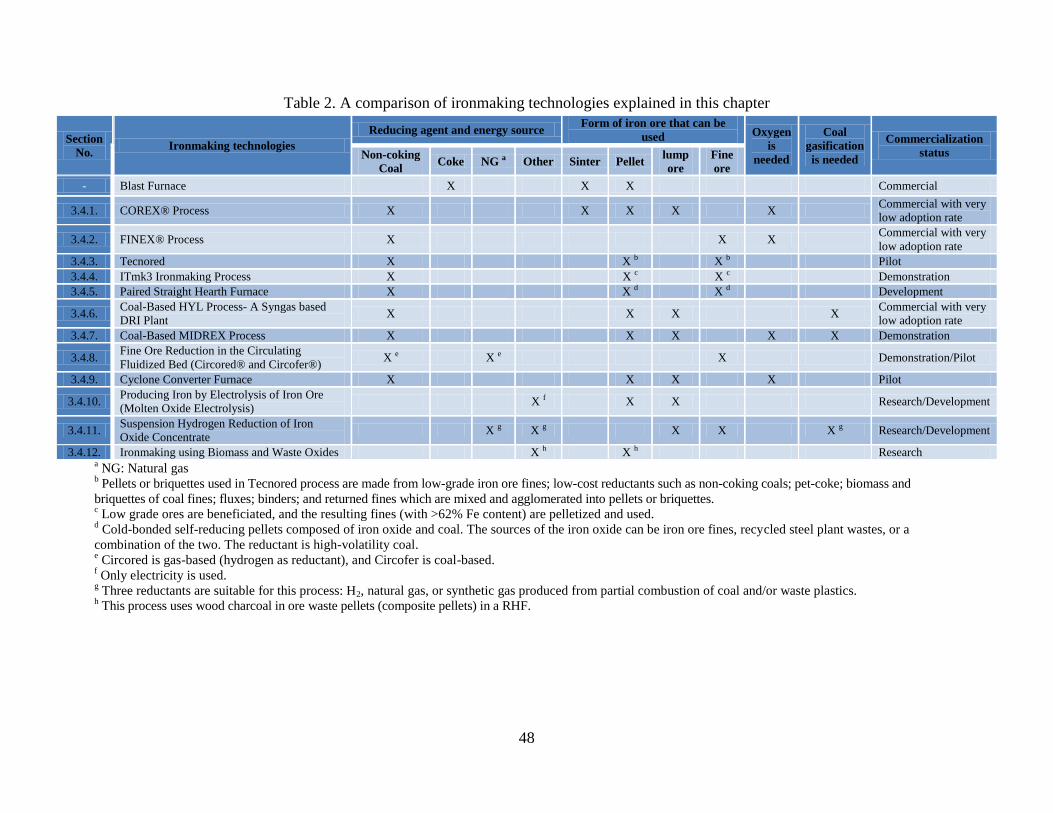
48
Table 2. A comparison of ironmaking technologies explained in this chapter
Section
No. Ironmaking technologies
Reducing agent and energy source Form of iron ore that can be
used Oxygen
is
needed
Coal
gasification
is needed
Commercialization
status Non-coking
Coal Coke NG a Other Sinter Pellet
lump
ore
Fine
ore
- Blast Furnace X X X Commercial
3.4.1. COREX® Process X X X X X Commercial with very
low adoption rate
3.4.2. FINEX® Process X X X Commercial with very
low adoption rate
3.4.3. Tecnored X X b X b Pilot
3.4.4. ITmk3 Ironmaking Process X X c X c Demonstration
3.4.5. Paired Straight Hearth Furnace X X d X d Development
3.4.6. Coal-Based HYL Process- A Syngas based
DRI Plant X X X X
Commercial with very
low adoption rate
3.4.7. Coal-Based MIDREX Process X X X X X Demonstration
3.4.8. Fine Ore Reduction in the Circulating
Fluidized Bed (Circored® and Circofer®) X e X e X Demonstration/Pilot
3.4.9. Cyclone Converter Furnace X X X X Pilot
3.4.10. Producing Iron by Electrolysis of Iron Ore
(Molten Oxide Electrolysis) X f X X Research/Development
3.4.11. Suspension Hydrogen Reduction of Iron
Oxide Concentrate X g X g X X X g Research/Development
3.4.12. Ironmaking using Biomass and Waste Oxides X h X h Research a NG: Natural gas
b Pellets or briquettes used in Tecnored process are made from low-grade iron ore fines; low-cost reductants such as non-coking coals; pet-coke; biomass and
briquettes of coal fines; fluxes; binders; and returned fines which are mixed and agglomerated into pellets or briquettes. c Low grade ores are beneficiated, and the resulting fines (with >62% Fe content) are pelletized and used.
d Cold-bonded self-reducing pellets composed of iron oxide and coal. The sources of the iron oxide can be iron ore fines, recycled steel plant wastes, or a
combination of the two. The reductant is high-volatility coal. e Circored is gas-based (hydrogen as reductant), and Circofer is coal-based.
f Only electricity is used.
g Three reductants are suitable for this process: H2, natural gas, or synthetic gas produced from partial combustion of coal and/or waste plastics.
h This process uses wood charcoal in ore waste pellets (composite pellets) in a RHF.
49
3.5. Emerging Technologies for Steelmaking Shops
The subsections below describe the following emerging technologies to reduce energy use and
CO2 emissions in the steel making shop: sensible heat recovery from EAF off gas,
electrochemical de-zincing of steel scrap, continuous horizontal sidewall scrap charging, scrap-
based steelmaking using predominantly primary energy, ECOARC, BOF and EAF post-
combustion optimization using CFD modeling, laser-based optimization of EAF post combustion,
model-based steel temperature measurement for EAFs, real-time measurement of melt
constituents, and the continuous EAF steelmaking technology.
3.5.1. Sensible Heat Recovery from Electric Arc Furnace Off Gas
Description:
Because almost 70 percent of the energy losses in EAF steelmaking are associated with the off
gas, through which approximately 15.5 percent of EAF energy inputs are lost as sensible heat,
heat recovery could save substantial energy in EAFs. Combined with uncombusted CO that
subsequently burns in the post-combustion chamber, the total thermal energy that can be
recovered is more than 25 percent of EAF energy inputs. This is the amount of off-gas energy
needed for viable off-gas heat recovery.
Despite the significant potential benefits, EAF off-gas heat recovery is not commonly practiced,
in part because of the harsh environment in the fume system and the on-off batch nature of the
process (Zuliani et al. 2010).
Tenova GmbH has adapted evaporative cooling system technology for EAF heat recovery. This
system replaces conventional low-pressure water-cooled ducting with high-pressure boiler tubes
designed to withstand the harsh EAF fume system conditions at pressures of 15 to 40 bar.
Tenova’s evaporative cooling system technology uses the heat of evaporation to produce high-
pressure steam at 216°C; the off-gas temperature at the exit of the cooled part of the waste gas
duct is reduced to about 600°C. The resulting high-pressure steam can be used to supplement or
replace an in-plant steam generation boiler for existing applications within the plant such as for
vacuum de-gassing or for in-plant DRI production using the HYL direct reduction process. With
steam accumulator tanks to homogenize EAF process cycles, this technology has demonstrated
continuous steam production with an average rate of 20 t/h from a 140 t/h EAF (Zuliani et al.
2010).
For a 140 t/h EAF, the EAF off-gas heat recovery technology would eliminate boiler-equivalent
CO2 emissions of almost 112,500 t CO2/year (with coal firing) or 57,000 t CO2/year (with natural
gas firing). It is also possible to add a second stage in which the off-gas temperature is reduced
from ~600°C to ~200°C with a waste heat boiler instead of the standard off-gas quench. The
combined heat recovery using both the evaporative cooling system and the waste heat boiler is 75
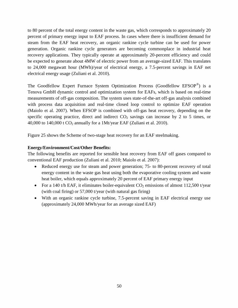
50
to 80 percent of the total energy content in the waste gas, which corresponds to approximately 20
percent of primary energy input to EAF process. In cases where there is insufficient demand for
steam from the EAF heat recovery, an organic rankine cycle turbine can be used for power
generation. Organic rankine cycle generators are becoming commonplace in industrial heat
recovery applications. They typically operate at approximately 20-percent efficiency and could
be expected to generate about 4MW of electric power from an average-sized EAF. This translates
to 24,000 megawatt hour (MWh)/year of electrical energy, a 7.5-percent savings in EAF net
electrical energy usage (Zuliani et al. 2010).
The Goodfellow Expert Furnace System Optimization Process (Goodfellow EFSOP®) is a
Tenova GmbH dynamic control and optimization system for EAFs, which is based on real-time
measurements of off-gas composition. The system uses state-of-the-art off-gas analysis combined
with process data acquisition and real-time closed loop control to optimize EAF operation
(Maiolo et al. 2007). When EFSOP is combined with off-gas heat recovery, depending on the
specific operating practice, direct and indirect CO2 savings can increase by 2 to 5 times, or
40,000 to 140,000 t CO2 annually for a 1Mt/year EAF (Zuliani et al. 2010).
Figure 25 shows the Scheme of two-stage heat recovery for an EAF steelmaking.
Energy/Environment/Cost/Other Benefits:
The following benefits are reported for sensible heat recovery from EAF off gases compared to
conventional EAF production (Zuliani et al. 2010; Maiolo et al. 2007):
Reduced energy use for steam and power generation; 75- to 80-percent recovery of total
energy content in the waste gas heat using both the evaporative cooling system and waste
heat boiler, which equals approximately 20 percent of EAF primary energy input
For a 140 t/h EAF, it eliminates boiler-equivalent CO2 emissions of almost 112,500 t/year
(with coal firing) or 57,000 t/year (with natural gas firing)
With an organic rankine cycle turbine, 7.5-percent saving in EAF electrical energy use
(approximately 24,000 MWh/year for an average sized EAF)
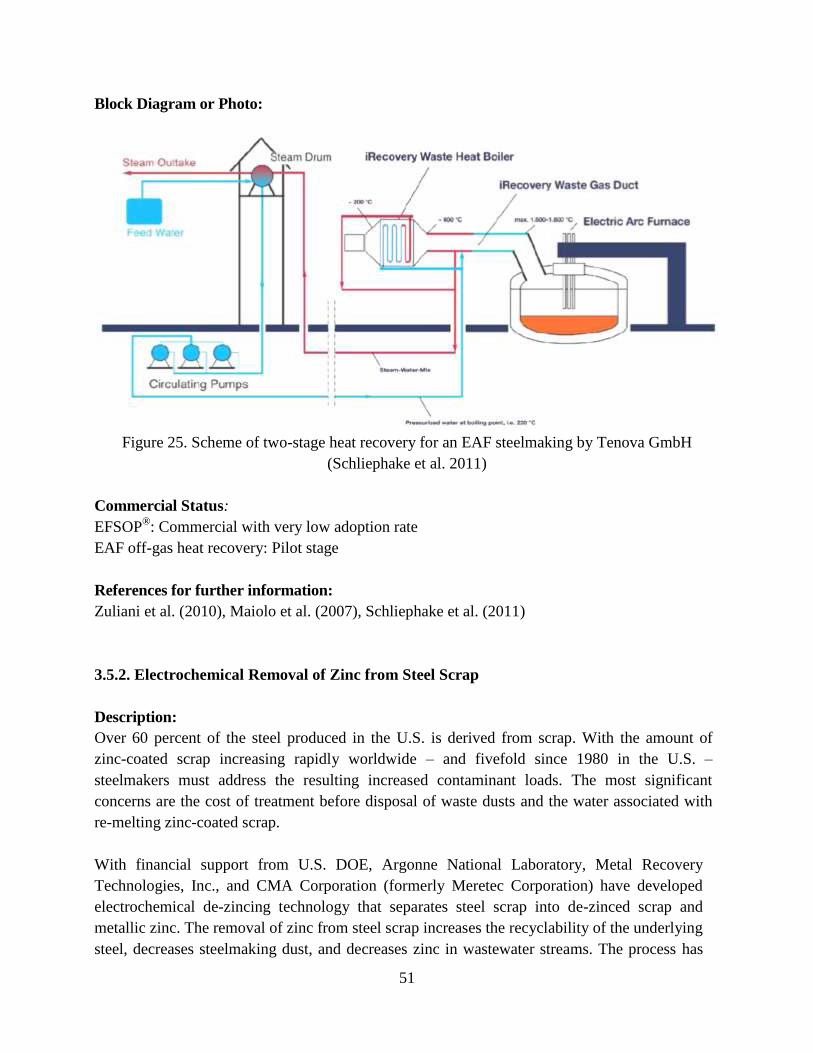
51
Block Diagram or Photo:
Figure 25. Scheme of two-stage heat recovery for an EAF steelmaking by Tenova GmbH
(Schliephake et al. 2011)
Commercial Status:
EFSOP®: Commercial with very low adoption rate
EAF off-gas heat recovery: Pilot stage
References for further information:
Zuliani et al. (2010), Maiolo et al. (2007), Schliephake et al. (2011)
3.5.2. Electrochemical Removal of Zinc from Steel Scrap
Description:
Over 60 percent of the steel produced in the U.S. is derived from scrap. With the amount of
zinc-coated scrap increasing rapidly worldwide – and fivefold since 1980 in the U.S. –
steelmakers must address the resulting increased contaminant loads. The most significant
concerns are the cost of treatment before disposal of waste dusts and the water associated with
re-melting zinc-coated scrap.
With financial support from U.S. DOE, Argonne National Laboratory, Metal Recovery
Technologies, Inc., and CMA Corporation (formerly Meretec Corporation) have developed
electrochemical de-zincing technology that separates steel scrap into de-zinced scrap and
metallic zinc. The removal of zinc from steel scrap increases the recyclability of the underlying
steel, decreases steelmaking dust, and decreases zinc in wastewater streams. The process has
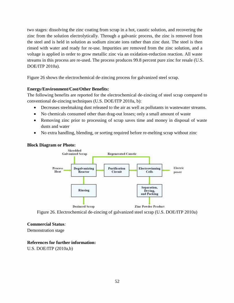
52
two stages: dissolving the zinc coating from scrap in a hot, caustic solution, and recovering the
zinc from the solution electrolytically. Through a galvanic process, the zinc is removed from
the steel and is held in solution as sodium zincate ions rather than zinc dust. The steel is then
rinsed with water and ready for re-use. Impurities are removed from the zinc solution, and a
voltage is applied in order to grow metallic zinc via an oxidation-reduction reaction. All waste
streams in this process are re-used. The process produces 99.8 percent pure zinc for resale (U.S.
DOE/ITP 2010a).
Figure 26 shows the electrochemical de-zincing process for galvanized steel scrap.
Energy/Environment/Cost/Other Benefits:
The following benefits are reported for the electrochemical de-zincing of steel scrap compared to
conventional de-zincing techniques (U.S. DOE/ITP 2010a, b):
Decreases steelmaking dust released to the air as well as pollutants in wastewater streams.
No chemicals consumed other than drag-out losses; only a small amount of waste
Removing zinc prior to processing of scrap saves time and money in disposal of waste
dusts and water
No extra handling, blending, or sorting required before re-melting scrap without zinc
Block Diagram or Photo:
Figure 26. Electrochemical de-zincing of galvanized steel scrap (U.S. DOE/ITP 2010a)
Commercial Status:
Demonstration stage
References for further information:
U.S. DOE/ITP (2010a,b)
Electric
power
53
3.5.3. Continuous Horizontal Sidewall Scrap Charging
Description:
Scrap charging and preheating for EAFs have been used in many forms during the past 30 years.
The majority of steelmakers use buckets to top charge scrap into the furnace. SMS Siemag Inc.
has developed an alternative system called continuous horizontal sidewall scrap charging. The
continuous horizontal sidewall scrap charger is most like a scrap baler or logger except the end
open to the furnace is unconstrained, so the scrap is uncompressed and permitted to fall into the
furnace. SMS Siemag Inc. claims that a continuous horizontal sidewall scrap charger provides the
same performance as scrap preheaters without the typical problems such as frequent maintenance,
environmental concerns, space constraints, and the need for a post-combustion burner (Cotchen
and Stercho 2002).
Energy/Environment/Cost/Other Benefits:
SMS Siemag Inc. claims the following benefits of the continuous horizontal sidewall scrap
charger (APP 2010):
Lower energy consumption from elimination of open roof during charging
Combustibles in the scrap burn in the furnace, which adds to furnace energy input
After-burners not required, which increases overall process efficiency
Scrap cave-ins (which break electrodes) eliminated by flat-bath operation
Consistent foamy slag produced by bath operation, which enhances efficiency and
prevents nitrogen pickup
Reduced furnace idle time, which leads to lower electrode oxidation and consumption
Lower losses and reduced power use from shorter tap-to-tap times
Less restrictive scrap sizing requirements, which lowers overall production costs
Lower refractory consumption due to less mechanical damage and thermal shock
Block Diagram or Photo:
N/A
Commercial Status:
Pilot stage
References for further information:
Cotchen and Stercho (2002), APP (2010)
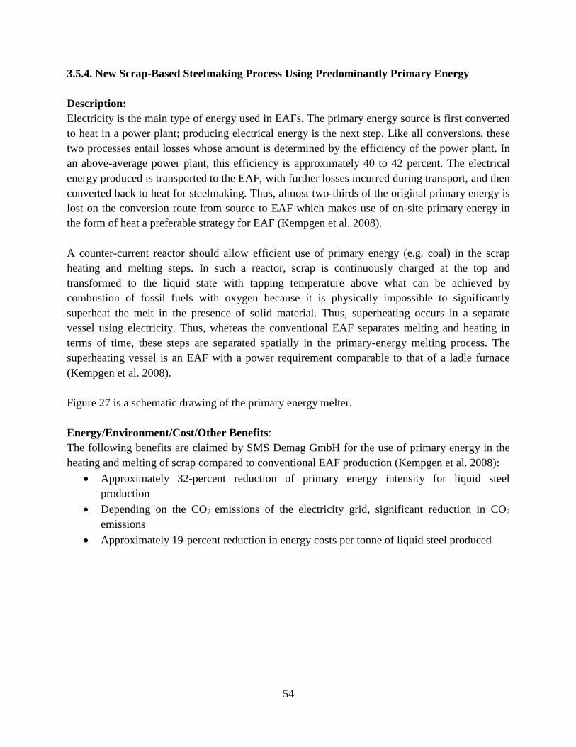
54
3.5.4. New Scrap-Based Steelmaking Process Using Predominantly Primary Energy
Description:
Electricity is the main type of energy used in EAFs. The primary energy source is first converted
to heat in a power plant; producing electrical energy is the next step. Like all conversions, these
two processes entail losses whose amount is determined by the efficiency of the power plant. In
an above-average power plant, this efficiency is approximately 40 to 42 percent. The electrical
energy produced is transported to the EAF, with further losses incurred during transport, and then
converted back to heat for steelmaking. Thus, almost two-thirds of the original primary energy is
lost on the conversion route from source to EAF which makes use of on-site primary energy in
the form of heat a preferable strategy for EAF (Kempgen et al. 2008).
A counter-current reactor should allow efficient use of primary energy (e.g. coal) in the scrap
heating and melting steps. In such a reactor, scrap is continuously charged at the top and
transformed to the liquid state with tapping temperature above what can be achieved by
combustion of fossil fuels with oxygen because it is physically impossible to significantly
superheat the melt in the presence of solid material. Thus, superheating occurs in a separate
vessel using electricity. Thus, whereas the conventional EAF separates melting and heating in
terms of time, these steps are separated spatially in the primary-energy melting process. The
superheating vessel is an EAF with a power requirement comparable to that of a ladle furnace
(Kempgen et al. 2008).
Figure 27 is a schematic drawing of the primary energy melter.
Energy/Environment/Cost/Other Benefits:
The following benefits are claimed by SMS Demag GmbH for the use of primary energy in the
heating and melting of scrap compared to conventional EAF production (Kempgen et al. 2008):
Approximately 32-percent reduction of primary energy intensity for liquid steel
production
Depending on the CO2 emissions of the electricity grid, significant reduction in CO2
emissions
Approximately 19-percent reduction in energy costs per tonne of liquid steel produced
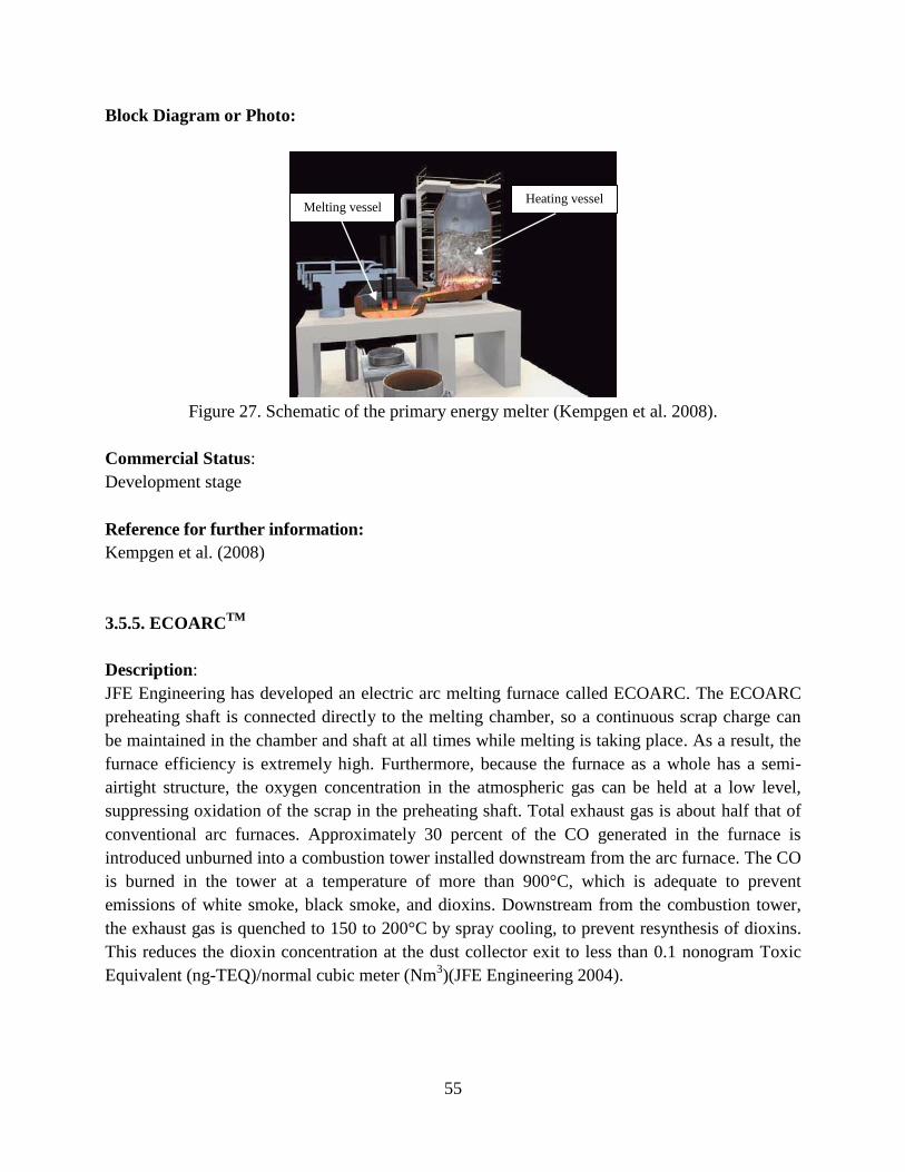
55
Block Diagram or Photo:
Figure 27. Schematic of the primary energy melter (Kempgen et al. 2008).
Commercial Status:
Development stage
Reference for further information:
Kempgen et al. (2008)
3.5.5. ECOARCTM
Description:
JFE Engineering has developed an electric arc melting furnace called ECOARC. The ECOARC
preheating shaft is connected directly to the melting chamber, so a continuous scrap charge can
be maintained in the chamber and shaft at all times while melting is taking place. As a result, the
furnace efficiency is extremely high. Furthermore, because the furnace as a whole has a semi-
airtight structure, the oxygen concentration in the atmospheric gas can be held at a low level,
suppressing oxidation of the scrap in the preheating shaft. Total exhaust gas is about half that of
conventional arc furnaces. Approximately 30 percent of the CO generated in the furnace is
introduced unburned into a combustion tower installed downstream from the arc furnace. The CO
is burned in the tower at a temperature of more than 900°C, which is adequate to prevent
emissions of white smoke, black smoke, and dioxins. Downstream from the combustion tower,
the exhaust gas is quenched to 150 to 200°C by spray cooling, to prevent resynthesis of dioxins.
This reduces the dioxin concentration at the dust collector exit to less than 0.1 nonogram Toxic
Equivalent (ng-TEQ)/normal cubic meter (Nm3)(JFE Engineering 2004).
Heating vessel Melting vessel
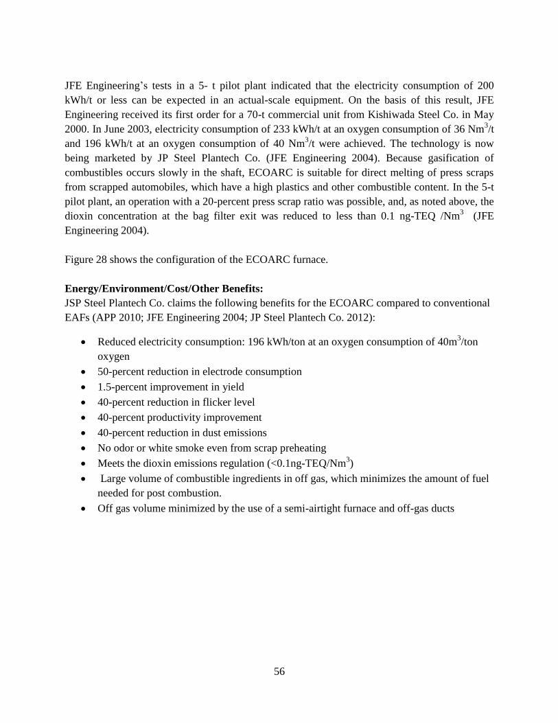
56
JFE Engineering’s tests in a 5- t pilot plant indicated that the electricity consumption of 200
kWh/t or less can be expected in an actual-scale equipment. On the basis of this result, JFE
Engineering received its first order for a 70-t commercial unit from Kishiwada Steel Co. in May
2000. In June 2003, electricity consumption of 233 kWh/t at an oxygen consumption of 36 Nm3/t
and 196 kWh/t at an oxygen consumption of 40 Nm3/t were achieved. The technology is now
being marketed by JP Steel Plantech Co. (JFE Engineering 2004). Because gasification of
combustibles occurs slowly in the shaft, ECOARC is suitable for direct melting of press scraps
from scrapped automobiles, which have a high plastics and other combustible content. In the 5-t
pilot plant, an operation with a 20-percent press scrap ratio was possible, and, as noted above, the
dioxin concentration at the bag filter exit was reduced to less than 0.1 ng-TEQ /Nm3 (JFE
Engineering 2004).
Figure 28 shows the configuration of the ECOARC furnace.
Energy/Environment/Cost/Other Benefits:
JSP Steel Plantech Co. claims the following benefits for the ECOARC compared to conventional
EAFs (APP 2010; JFE Engineering 2004; JP Steel Plantech Co. 2012):
Reduced electricity consumption: 196 kWh/ton at an oxygen consumption of 40m3/ton
oxygen
50-percent reduction in electrode consumption
1.5-percent improvement in yield
40-percent reduction in flicker level
40-percent productivity improvement
40-percent reduction in dust emissions
No odor or white smoke even from scrap preheating
Meets the dioxin emissions regulation (<0.1ng-TEQ/Nm3)
Large volume of combustible ingredients in off gas, which minimizes the amount of fuel
needed for post combustion.
Off gas volume minimized by the use of a semi-airtight furnace and off-gas ducts
57
Block Diagram or Photo:
Figure 28. Schematic configuration of ECOARC (JFE Engineering 2004).
Commercial Status:
Demonstration stage
References for further information:
JFE Engineering (2004), JP Steel Plantech Co. (2012)
3.5.6. Optimization of BOF and EAF Post Combustion Using CFD
Description:
The primary off gas from EAF and BOF steel production is CO. If the CO can be combusted to
CO2, and the energy transferred to the metal, this reaction reduces the energy consumed in the
EAF and allows for more scrap melting in the BOF. This reaction is referred to as post
combustion and significantly reduces the energy required to produce steel (Fruehan and Matway
2004).
Researchers at Carnegie Mellon University developed Computational Fluid Dynamics (CFD)
models for post combustion in EAFs and BOFs for use in optimizing these steelmaking processes.
The models include all relevant phenomena, such as radiant heat transfer, accurate combustion
reactions, and de-post combustion reactions. DOE/AISI’s TR Program supported the project
(AISI 2010).
58
The CFD EAF post-combustion model is a full 3-D, finite-volume technique with more than
200,000 elements. The CFX™ code was used for modeling. The software models a three-phase,
200-t alternating current electric arc furnace with a primary oxygen lance and four wall-mounted
oxygen injectors for post combustion. Special models were developed to describe the combustion
and de-post combustion reactions and fluid flow in the foamed slag. The model can predict the
degree of post combustion and heat transfer. Based on the EAF model, the researchers developed
a CFD post-combustion model for the BOF using a slice of the furnace for which there was
symmetry. The program modeled a 250-t BOF with 10 post-combustion injectors located 2 to 2.5
meters above the primary oxygen jet at the bottom of the lance. The model can predict post
combustion, heat transfer, temperature profiles, and the effect of operating variables such as
oxygen flow rates and distribution. Instruction manuals were developed so that the models can be
used by industry (AISI 2010; Fruehan and Matway 2004).
Energy/Environment/Cost/Other Benefits:
Optimized post combustion would (AISI 2010):
Reduce the energy consumed in the EAF
Allow for more scrap melting in the BOF, which would significantly lower the energy
required to produce steel using the BF-BOF route
Block Diagram or Photo:
N/A
Commercial Status:
Pilot stage
References for further information:
AISI (2010), Fruehan and Matway (2004)
3.5.7. Improving the Energy Efficiency of EAF through Laser-based Optimization of Post
Combustion
Description:
The proper melting time is crucial in EAF steelmaking. The time should be long enough to melt
the scrap entirely but not longer than the time needed for post combustion from CO to CO2. The
quality of the scrap as well as the post combustion time to convert CO to CO2 therefore determine
the melting time (BFI 2009/2010).
In a project funded by BMWi (the German Federal Ministry of Economics and Technology) a
laser based off-gas analysis system for EAF steelmaking was developed to analyze in detail the
59
conditions in the off gas, which vary considerably over time. With the help of a dynamic mass
and energy balance model, the energy performance of the furnace was analyzed and evaluated as
a function of the energy losses via the furnace off gas. This enabled the post-combustion oxygen
feed rate to be controlled in a targeted manner, allowing improved use of the chemical energy
content of the furnace off gas for the melting process. Optimizing the operating regimes for post-
combustion oxygen input over time decreased the electrical energy demand of the furnace by
about 17 kWh/t or 4 percent of the energy input (Figure 29) (BFI 2009/2010).
If the post-combustion oxygen feed rate is controlled dynamically based on continuous off-gas
measurement and analysis, this should allow even more thorough exploitation of the chemical
energy in the furnace off gas for each individual process. Further energy savings could also be
achieved through on-line use of a dynamic energy balance model to check the melt temperature
end point. This allows the operator to avoid overheating of the melt beyond the target tapping
temperature (BFI 2009/2010).
Energy/Environment/Cost/Other Benefits:
The following benefit can be achieved when laser-based optimization of post combustion is applied
to EAF steelmaking, compared to the conventional EAF production (BFI 2009/2010):
Reduction of about 17 kWh/t or 4 percent in electrical energy demand
Block Diagram or Photo:
N/A
Commercial Status:
Pilot stage
Reference for further information:
BFI (2009/2010)
3.5.8. Model-based Steel Temperature Measurement for Electric Arc Furnaces
Description:
Maintaining the required target temperature is crucial in EAF steelmaking. Continuous
monitoring of the liquid steel temperature enables optimal control of the electrical energy
required to heat the melt and precise adjustment of the target temperature.
A new measurement and control concept was developed for EAFs in a project funded by BMWi
(the German Federal Ministry of Economics and Technology). The temperature measurement
system consists of a measuring unit, lance, and manipulator and is based on the use of an optical
fiber that is immersed in the molten metal using BFI’s DynTemp® technique. The optical
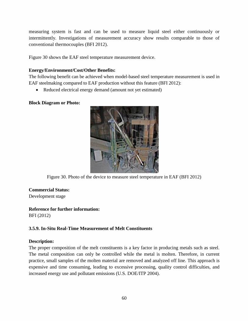
60
measuring system is fast and can be used to measure liquid steel either continuously or
intermittently. Investigations of measurement accuracy show results comparable to those of
conventional thermocouples (BFI 2012).
Figure 30 shows the EAF steel temperature measurement device.
Energy/Environment/Cost/Other Benefits:
The following benefit can be achieved when model-based steel temperature measurement is used in
EAF steelmaking compared to EAF production without this feature (BFI 2012):
Reduced electrical energy demand (amount not yet estimated)
Block Diagram or Photo:
Figure 30. Photo of the device to measure steel temperature in EAF (BFI 2012)
Commercial Status:
Development stage
Reference for further information:
BFI (2012)
3.5.9. In-Situ Real-Time Measurement of Melt Constituents
Description:
The proper composition of the melt constituents is a key factor in producing metals such as steel.
The metal composition can only be controlled while the metal is molten. Therefore, in current
practice, small samples of the molten material are removed and analyzed off line. This approach is
expensive and time consuming, leading to excessive processing, quality control difficulties, and
increased energy use and pollutant emissions (U.S. DOE/ITP 2004).
61
Approximately 3 percent of all steel produced is downgraded or scrapped and that 50 percent of the
downgraded or scrapped material needs complete rework. In-line measurements and closed-loop
control can be a key to eliminating this waste.
A new technology developed by the Energy Research Company employs a laser-induced
breakdown spectroscopic (LIBS) technique to measure, in-situ and in real-time, the constituents of
the melt in a process furnace (U.S. DOE/OTI 2001). A probe is placed inside the melt, and a laser
is fired repetitively through a fiberoptic cable and through the probe. A small amount of melt at the
probe tip absorbs the laser light, producing temperatures sufficiently high to heat and vaporize the
melt sample into a gaseous plasma state. The resulting plasma emits a signal that is detected and
sent to a spectrometer. This signal is spectrally resolved to uniquely identify the elements in the
melt and the concentration of each element present (U.S. DOE/ITP 2004).
The system is self calibrating, and no training is required to use it. Its use enables increased
production and maintenance of tighter compositional tolerances than have been possible in the past
(De Saro et al. 2005b).
Two commercial installations have been completed, one in the aluminum industry and one in the
glass industry. The laser-induced breakdown spectroscopic system is permanently installed in a
glass manufacturing facility and is routinely used. High degrees of accuracy and repeatability are
achievable with this system. The installation in the aluminum industry has shown that the laser-
induced breakdown spectroscopic system is as accurate as conventional spark spectrometers (De
Saro et al. 2005a). At an early stage of development, the system was also used to measure
elemental concentrations of solid steel samples. Since then, the techniques have been refined. There
have so far been no industrial-scale applications of this system in the steel industry, as more
development work is needed for its application in the steel industry (De Saro et al. 2005b).
Figures 31 and 32 show the basic laser-induced breakdown spectroscopic system and its application
to molten material.
Energy/Environment/Cost/Other Benefits:
The following benefits can be achieved by in-situ real-time measurement of melt constituents
compared to steel production without this feature (De Saro et al. 2005b, U.S. DOE/ITP 2004):
Energy savings and CO2 reductions because of reduction of downgraded or scrapped
material
Increased production and tighter compositional tolerances
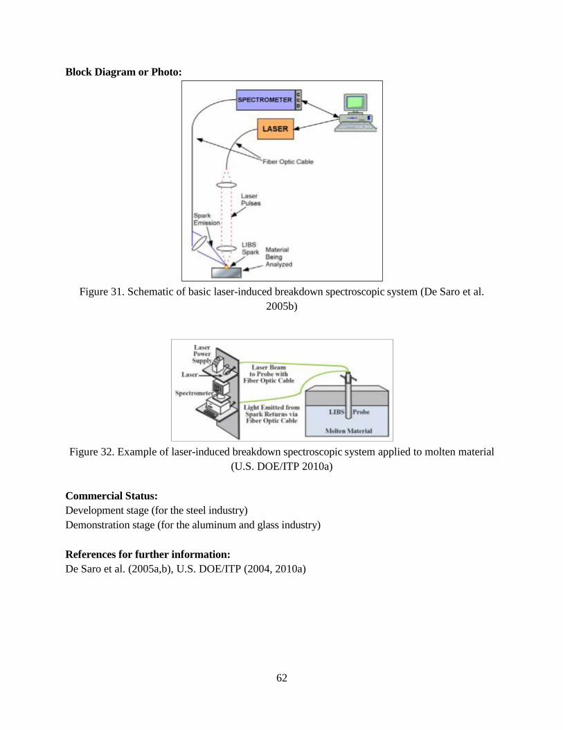
62
Block Diagram or Photo:
Figure 31. Schematic of basic laser-induced breakdown spectroscopic system (De Saro et al.
2005b)
Figure 32. Example of laser-induced breakdown spectroscopic system applied to molten material
(U.S. DOE/ITP 2010a)
Commercial Status:
Development stage (for the steel industry)
Demonstration stage (for the aluminum and glass industry)
References for further information:
De Saro et al. (2005a,b), U.S. DOE/ITP (2004, 2010a)
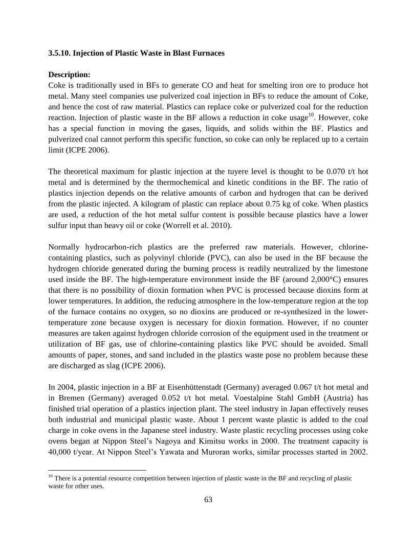
63
3.5.10. Injection of Plastic Waste in Blast Furnaces
Description:
Coke is traditionally used in BFs to generate CO and heat for smelting iron ore to produce hot
metal. Many steel companies use pulverized coal injection in BFs to reduce the amount of Coke,
and hence the cost of raw material. Plastics can replace coke or pulverized coal for the reduction
reaction. Injection of plastic waste in the BF allows a reduction in coke usage10
. However, coke
has a special function in moving the gases, liquids, and solids within the BF. Plastics and
pulverized coal cannot perform this specific function, so coke can only be replaced up to a certain
limit (ICPE 2006).
The theoretical maximum for plastic injection at the tuyere level is thought to be 0.070 t/t hot
metal and is determined by the thermochemical and kinetic conditions in the BF. The ratio of
plastics injection depends on the relative amounts of carbon and hydrogen that can be derived
from the plastic injected. A kilogram of plastic can replace about 0.75 kg of coke. When plastics
are used, a reduction of the hot metal sulfur content is possible because plastics have a lower
sulfur input than heavy oil or coke (Worrell et al. 2010).
Normally hydrocarbon-rich plastics are the preferred raw materials. However, chlorine-
containing plastics, such as polyvinyl chloride (PVC), can also be used in the BF because the
hydrogen chloride generated during the burning process is readily neutralized by the limestone
used inside the BF. The high-temperature environment inside the BF (around 2,000°C) ensures
that there is no possibility of dioxin formation when PVC is processed because dioxins form at
lower temperatures. In addition, the reducing atmosphere in the low-temperature region at the top
of the furnace contains no oxygen, so no dioxins are produced or re-synthesized in the lower-
temperature zone because oxygen is necessary for dioxin formation. However, if no counter
measures are taken against hydrogen chloride corrosion of the equipment used in the treatment or
utilization of BF gas, use of chlorine-containing plastics like PVC should be avoided. Small
amounts of paper, stones, and sand included in the plastics waste pose no problem because these
are discharged as slag (ICPE 2006).
In 2004, plastic injection in a BF at Eisenhüttenstadt (Germany) averaged 0.067 t/t hot metal and
in Bremen (Germany) averaged 0.052 t/t hot metal. Voestalpine Stahl GmbH (Austria) has
finished trial operation of a plastics injection plant. The steel industry in Japan effectively reuses
both industrial and municipal plastic waste. About 1 percent waste plastic is added to the coal
charge in coke ovens in the Japanese steel industry. Waste plastic recycling processes using coke
ovens began at Nippon Steel’s Nagoya and Kimitsu works in . The treatment capacity is
4 , t/year. At Nippon Steel’s Yawata and Muroran works, similar processes started in .
10
There is a potential resource competition between injection of plastic waste in the BF and recycling of plastic
waste for other uses.
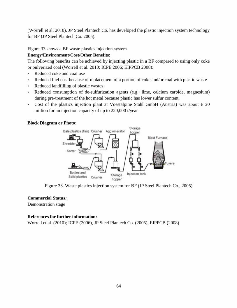
64
(Worrell et al. 2010). JP Steel Plantech Co. has developed the plastic injection system technology
for BF (JP Steel Plantech Co. 2005).
Figure 33 shows a BF waste plastics injection system.
Energy/Environment/Cost/Other Benefits:
The following benefits can be achieved by injecting plastic in a BF compared to using only coke
or pulverized coal (Worrell et al. 2010; ICPE 2006; EIPPCB 2008):
• Reduced coke and coal use
• Reduced fuel cost because of replacement of a portion of coke and/or coal with plastic waste
• Reduced landfilling of plastic wastes
• Reduced consumption of de-sulfurization agents (e.g., lime, calcium carbide, magnesium)
during pre-treatment of the hot metal because plastic has lower sulfur content.
• Cost of the plastics injection plant at Voestalpine Stahl GmbH (Austria) was about €
million for an injection capacity of up to 220,000 t/year
Block Diagram or Photo:
Figure 33. Waste plastics injection system for BF (JP Steel Plantech Co., 2005)
Commercial Status:
Demonstration stage
References for further information:
Worrell et al. (2010); ICPE (2006), JP Steel Plantech Co. (2005), EIPPCB (2008)
65
3.5.11. Injection of Plastic Waste in Electric Arc Furnaces
Description
EAF steelmaking uses carbon-based materials as slag foaming agents. Depending on cost and
availability, anthracite and metallurgical coke are often used as injection materials. Because of
increasing energy prices and GHG emissions, alternative carbon sources are gaining attention as
replacements for conventional materials. Waste materials such as high-density polyethylene
plastics can react with gas and in slag phases resulting in de-volatilization, combustion, and iron
oxide reduction reactions. The addition of waste plastics in EAF steelmaking has been studied in
detail by The University of New South Wales and OneSteel with the goal of developing a method
for EAFs to use blends of different proportions of rubber/ high-density polyethylene plastics and
coke as a slag foaming agent (Sahajwalla et al. 2011).
A prototype scale process was able to replace 30 percent of the coke and coal with polyethylene
waste plastic. This new process has demonstrated the ability to accelerate the slag-foaming
process at the top of the melt, thereby saving energy. Consequently, a higher productivity is
achieved. In 2007, OneSteel carried out commercial trials at its Rooty Hill facility in Australia.
The first trials confirmed the speed-up of the slag foaming process with reduced electricity use.
The tap-to-tap time was also reduced. The technology is planned to be implemented and further
developed at the OneSteel Laverton facility (Worrell et al. 2010).
Sahajwalla et al. (2010) also investigated the combustion efficiencies of blends of metallurgical
coke with plastics for EAF steelmaking. Laboratory tests for coke-plastic blends indicated higher
combustion efficiencies compared to coke (Sahajwalla et al. 2011).
Energy/Environment/Cost/Other Benefits:
The following benefits can be achieved by injecting waste plastics in EAFs compared to using
only coal (Worrell et al. 2010):
Estimated energy savings of around 12 kWh/t of plastic charge
Reduced CO2 emissions
Increased productivity by reducing tap-to-tap time
Reduced landfilling of plastic waste
Block Diagram or Photo:
N/A
Commercial Status:
Pilot stage
References for further information:
Worrell et al. (2010), Sahajwalla et al. (2010, 2011)
66
3.5.12. Use of Waste Tires in Electric Arc Furnaces
Description
Steel making in an electric arc furnace is based on the principle of subjecting scrap metal to a
high temperature (1,650 °C) for about 45 minutes until the metal becomes molten. An electric arc
(temperature greater than 15,00 °C) provides the gradual rise in temperature. Normally in an EAF
furnace, approximately 3.3t of lime and 1.15t of carbon in the form of anthracite and coke are
added for every 100 t of scrap metal (Clauzade 2006).
Rubber tires contain a large amount of carbon and energy and are available at lower costs than
other potential alternative fuels. Additionally, the ever-increasing use of tires poses serious
disposal problems in landfills because they do not biodegrade. Tires are generally disposed of in
landfills and by incineration and to some extent co-processing in cement kilns; however,
landfilling and incineration are becoming unattractive because of diminishing landfill space and
for legislative reasons. Scrap tires make a good carbon source for EAF steel melting. The tires are
added to the EAF as a source of chemical energy, replacing coal or coke. The carbon and
hydrogen in the tires provide fuel energy, and the steel belts and beads become part of the
material in the furnace. Oxygen is injected into the furnaces while the tires are burning so that
combustion is clean and complete. The tires are completely consumed in the process. Contrary to
popular belief, there is no increase in emissions from burning tires in an EAF. A 9-kg passenger
tire has a fuel value of approximately 332 MJ. Tires have a higher heating value than that of coal
and coke on a per-weight basis. Two or more passenger tires can be added per tonne of steel. Tire
disposal fees that steel plants may receive for tires they burn can also result in a significant
revenue per tonne of steel. Scrap tires contain 1.5 percent sulfur, which compares favorably with
the sulfur content of most coal and coke. When scrap tires are used in the EAF, they do not cause
any noticeable change in steel chemistry other than an increase in carbon if desired (Stebbing
2005).
Under experimental conditions, Zaharia et al. (2009) showed that most of the rubber/coke blends
had higher combustion efficiencies than those of constituent coke in an EAF (Zaharia et al. 2009).
An industrial trial of using scrap tires in EAF, carried out by Joulazadeh (2008) at Esfahan Steel
Co. in Iran, showed that coke consumption reduced from 18.0 kg/t steel to zero and electricity
consumption decreased from 448 to 388 kWh/t. The study also found that the amounts of gaseous
pollutants released, such as CO, NOx, and SO2, were far lower than the permitted limits
(Joulazadeh 2008).
EAFs in the U.S. began to use scrap tires as a source of carbon and steel by introducing the whole
tire into the charge bucket. Also, since 1999, rubber tires have been used as a substitute for coal
and iron scraps in the scrap melting converter of Nippon Steel Corporation in its Hirohata, Japan
mill. The procedure involves cutting the waste tires to smaller dimensions and charging them into
the scrap melting bath along with the steel cords contained in the tires (Zaharia et al. 2009). Since
67
2006, the LME site at Trith-Saint-Leger in France, which is capable of processing 7,000 tonnes
of scrap tires annually, has implemented the recycling of scrap tires in its EAF (Clauzade 2006).
Energy/Environment/Cost/Other Benefits:
The following benefits can be achieved by injecting waste tires in an EAF compared to injecting
coal (Stebbing, 2005; Clauzade 2006):
Reduced coke and/or coal consumption
Reduced CO2 emissions
Reduced landfilling of waste tires
Block Diagram or Photo:
N/A
Commercial Status:
Commercial with very low adoption rate
References for further information:
Clauzade (2006), Stebbing (2005), Joulazadeh (2008)
3.5,13. Continuous Steelmaking for Electric Arc Furnace
Description:
High-quality EAF steelmaking is currently a batch process. To improve productivity and energy
efficiency, a continuous process from liquid steel to the casting mold is under development through
the U.S. DOE Industrial Technologies Program (U.S. DOE/ITP 2005).
Current EAF shops consist of an EAF, a ladle metallurgy furnace, and a continuous caster. The
proposed process replaces the ladle metallurgy furnace and the continuous caster with a continuous
process including several vessels (oxidizer, reducer, finisher, and tundish). The process would be
designed for variable production rates ranging from 70 t/h to 170 t/h (Peaslee et al. 2006).
The process has been modeled as follows: Preheated scrap is continuously charged and melted in
the EAF, and final de-carbonization and de-phosphorization take place in a second vessel, the
oxidizer. In the reducer, steel is continuously de-oxidized, de-sulfurized, and alloyed. Once the steel
has a composition that is close to the final chemistry, it enters the fourth vessel, the finisher. The
operations in the finisher include final trimming, additional de-sulfurization, inclusion floatation,
and homogenization before the steel flows into the last vessel, the tundish (Peaslee et al. 2006). So
far, the process has been modeled, and laboratory experiments have been conducted to validate the
simulations.
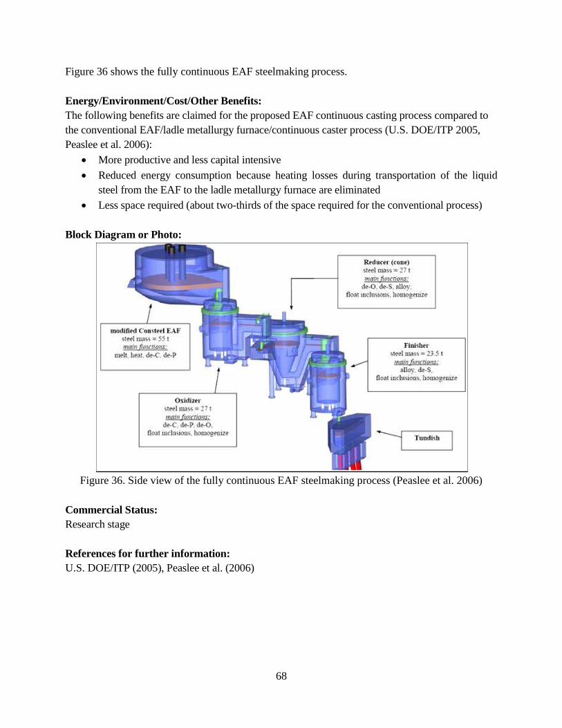
68
Figure 36 shows the fully continuous EAF steelmaking process.
Energy/Environment/Cost/Other Benefits:
The following benefits are claimed for the proposed EAF continuous casting process compared to
the conventional EAF/ladle metallurgy furnace/continuous caster process (U.S. DOE/ITP 2005,
Peaslee et al. 2006):
More productive and less capital intensive
Reduced energy consumption because heating losses during transportation of the liquid
steel from the EAF to the ladle metallurgy furnace are eliminated
Less space required (about two-thirds of the space required for the conventional process)
Block Diagram or Photo:
Figure 36. Side view of the fully continuous EAF steelmaking process (Peaslee et al. 2006)
Commercial Status:
Research stage
References for further information:
U.S. DOE/ITP (2005), Peaslee et al. (2006)
69
3.6. Emerging Casting Technologies
The subsections below describe the following emerging technologies to save energy and reduce
CO2 emissions from the steel casting process: near-net-shape casting, and continuous temperature
monitoring and control.
3.6.1. Near-net-shape Casting/Strip Casting
Description:11
“Near-net-shape casting entails casting metal to a form close to that required for the finished
product so that less machining is required to finish the steel than in conventional production.
Near-net-shape casting integrates the casting and hot rolling of steel into one process step,
thereby reducing the need to reheat the steel before rolling it. Several production processes have
been developed for near-net-shape casting, notably thin-slab casting and strip casting. In thin-slab
casting, the steel is cast directly to slabs that have a thickness of 30 to 60 mm rather than the
typical 120- to 300-mm thickness. Thin-slab casting has been a success in flat-product mini-mills
in the U.S. (Birat et al. 2003).
In strip casting, steel is cast between two rolls that produce a strip approximately 3 mm thick.
Development of near-net and strip casting started in 1975 in a number of countries: Europe,
Japan, Australia, the U.S., and Canada (Luiten and Blok 2003). Since then, three commercial
technologies have emerged. In all three, the steel is cast between two water-cooled rolls, which
results in very rapid cooling and high production speeds. The major advantage of strip casting is
a large reduction in capital costs because the process has a high productivity and integrates
several production steps (Sosinsky et al. 2008). The first commercial strip casting technologies
are:
1. Castrip®
: The Castrip®
consortium was formed to commercialize a product based on
technology developed by BHP (Australia) and IHI Japan. The third partner is Nucor (USA).
Nucor first introduced strip casting in the U.S. The first commercial strip caster was
constructed at Nucor’s Crawfordsville, Indiana plant in 2002. Since then, the plant has
produced ultra-thin cast strip products. The plant has a capacity of 540 kilotons (kt)/year.
Nucor also commenced construction of its second strip casting plant in Blytheville, Arkansas
(Sosinsky et al. 2008).
2. Eurostrip: Eurostrip is a consortium of ThyssenKrupp Steel, ArcelorMittal, and Voest
Alpine Industries. The first pilot plant was constructed in Terni, Italy, and the first
commercial plant opened in 1999 in Krefeld, Germany. The commercial plant focuses on
stainless steel casting. The technology is offered at a scale of 550 kt/year (Cramb 2004).
3. Nippon/Mitsubishi: A strip caster commissioned in October 1997 by Nippon Steel has an
output of 420 kt/year with an estimated fuel use of 0.05 GJ/t and electricity use of 42 kWh/t –
considerably less than the energy used by a continuous casting process. Operations and
11
Most of the text for this technology was excerpted from Worrell et al. (2010).
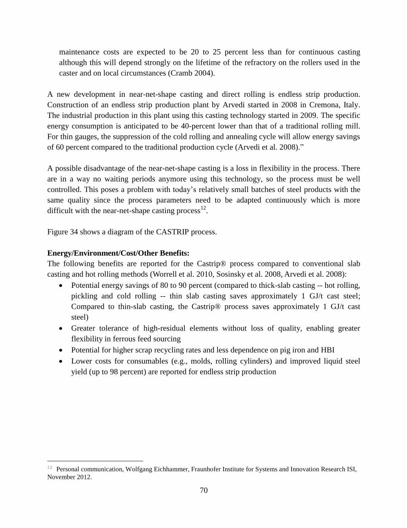
70
maintenance costs are expected to be 20 to 25 percent less than for continuous casting
although this will depend strongly on the lifetime of the refractory on the rollers used in the
caster and on local circumstances (Cramb 2004).
A new development in near-net-shape casting and direct rolling is endless strip production.
Construction of an endless strip production plant by Arvedi started in 2008 in Cremona, Italy.
The industrial production in this plant using this casting technology started in 2009. The specific
energy consumption is anticipated to be 40-percent lower than that of a traditional rolling mill.
For thin gauges, the suppression of the cold rolling and annealing cycle will allow energy savings
of 60 percent compared to the traditional production cycle (Arvedi et al. 2008).”
A possible disadvantage of the near-net-shape casting is a loss in flexibility in the process. There
are in a way no waiting periods anymore using this technology, so the process must be well
controlled. This poses a problem with today’s relatively small batches of steel products with the
same quality since the process parameters need to be adapted continuously which is more
difficult with the near-net-shape casting process12
.
Figure 34 shows a diagram of the CASTRIP process.
Energy/Environment/Cost/Other Benefits:
The following benefits are reported for the Castrip® process compared to conventional slab
casting and hot rolling methods (Worrell et al. 2010, Sosinsky et al. 2008, Arvedi et al. 2008):
Potential energy savings of 80 to 90 percent (compared to thick-slab casting -- hot rolling,
pickling and cold rolling -- thin slab casting saves approximately 1 GJ/t cast steel;
Compared to thin-slab casting, the Castrip® process saves approximately 1 GJ/t cast
steel)
Greater tolerance of high-residual elements without loss of quality, enabling greater
flexibility in ferrous feed sourcing
Potential for higher scrap recycling rates and less dependence on pig iron and HBI
Lower costs for consumables (e.g., molds, rolling cylinders) and improved liquid steel
yield (up to 98 percent) are reported for endless strip production
12 Personal communication, Wolfgang Eichhammer, Fraunhofer Institute for Systems and Innovation Research ISI,
November 2012.
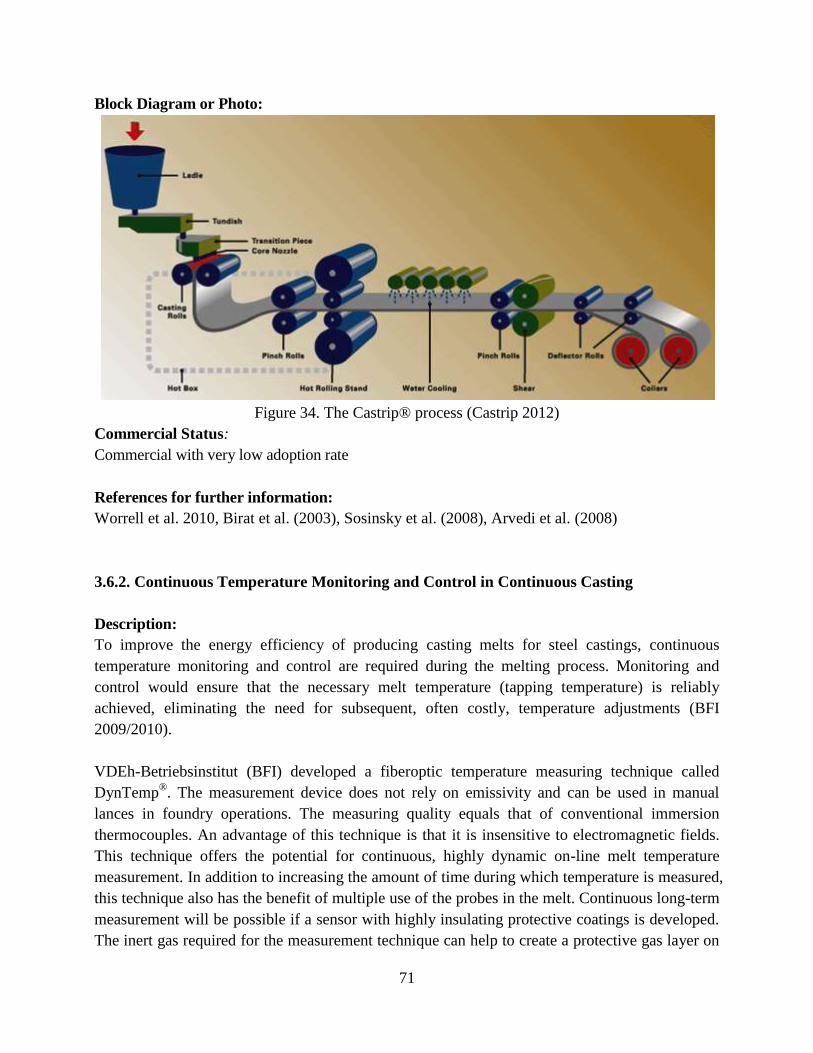
71
Block Diagram or Photo:
Figure 34. The Castrip® process (Castrip 2012)
Commercial Status:
Commercial with very low adoption rate
References for further information:
Worrell et al. 2010, Birat et al. (2003), Sosinsky et al. (2008), Arvedi et al. (2008)
3.6.2. Continuous Temperature Monitoring and Control in Continuous Casting
Description:
To improve the energy efficiency of producing casting melts for steel castings, continuous
temperature monitoring and control are required during the melting process. Monitoring and
control would ensure that the necessary melt temperature (tapping temperature) is reliably
achieved, eliminating the need for subsequent, often costly, temperature adjustments (BFI
2009/2010).
VDEh-Betriebsinstitut (BFI) developed a fiberoptic temperature measuring technique called
DynTemp®. The measurement device does not rely on emissivity and can be used in manual
lances in foundry operations. The measuring quality equals that of conventional immersion
thermocouples. An advantage of this technique is that it is insensitive to electromagnetic fields.
This technique offers the potential for continuous, highly dynamic on-line melt temperature
measurement. In addition to increasing the amount of time during which temperature is measured,
this technique also has the benefit of multiple use of the probes in the melt. Continuous long-term
measurement will be possible if a sensor with highly insulating protective coatings is developed.
The inert gas required for the measurement technique can help to create a protective gas layer on
72
the melt bath surface which will largely prevent re-oxidization of the melt. An improvement in
energy efficiency of up to 5 percent is expected from the use of the new temperature monitoring
and control system. (BFI 2009/2010).
Energy/Environment/Cost/Other Benefits:
BFI claims that the following benefits can be achieved from use of the DynTemp device compared
to conventional temperature measurement techniques (BFI 2009/2010):
Longer temperature measuring times
Energy-efficiency improvement of up to 5 percent
Commercial Status:
Development stage
Reference for further information:
BFI (2009/2010)
73
3.7. Emerging Rolling and Finishing Technologies
The subsections below describe the following emerging technologies that save energy and reduce
CO2 emissions in the rolling and finishing phases of steelmaking: oxygen enrichment of
combustion air combined with use of low-calorific gases, scale-free steel reheating,
thermochemical recuperation for reheating furnaces, the hot strip mill model, continuous burn-out
measurement for management of reheating furnaces, oxygen-rich furnace system for reduced
CO2 and NOx emissions, HotEye® steel surface inspection, and oscillating combustion for NOx
emissions reduction.
3.7.1. High-Temperature Membrane Module for Oxygen Enrichment of Combustion Air
for Fuel-Fired Industrial Furnaces
Description:
Industrial furnaces usually are operated with high-calorific gases (e.g., natural gas, converter gas).
If these gases are replaced by low-calorific gases (e.g., biogas), then the flame temperature
lowers. If the combustion air is replaced by oxygen, then the flame temperature can be increased
to levels of combustion that are possible with high-calorific gases (BFI 2009/2010).
The cost-efficient production of oxygen is crucial to this technique. In a project supported by the
German Federal Foundation for the Environment (Deutsche Bundesstiftung Umwelt), ceramic
membranes were developed in which oxygen is extracted from air with the help of waste heat
from the furnaces. This project demonstrated that the necessary furnace chamber temperature can
be achieved with low-calorific gases and oxygen (BFI 2009/2010).
Figure 37 shows a high-temperature membrane module on a furnace.
Energy/Environment/Cost/Other Benefits:
The following benefits can be achieved by the scalable high-temperature membrane modules for
oxygen enrichment of combustion air in fuel-fired industrial furnaces, compared to use of high-
calorific gases (BFI 2009/2010):
Reduced CO2 emissions (because biogas is considered carbon neutral)
Use of waste heat from the furnaces
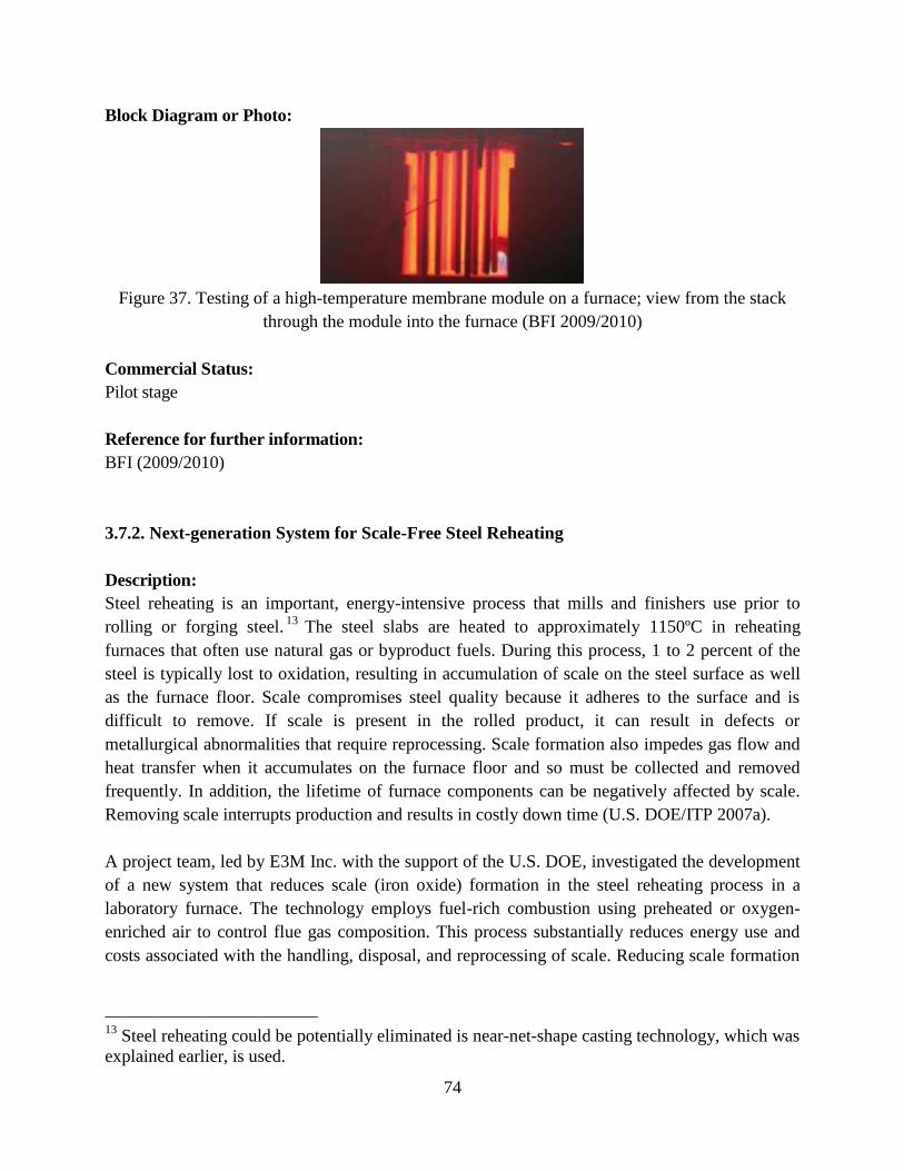
74
Block Diagram or Photo:
Figure 37. Testing of a high-temperature membrane module on a furnace; view from the stack
through the module into the furnace (BFI 2009/2010)
Commercial Status:
Pilot stage
Reference for further information:
BFI (2009/2010)
3.7.2. Next-generation System for Scale-Free Steel Reheating
Description:
Steel reheating is an important, energy-intensive process that mills and finishers use prior to
rolling or forging steel.13
The steel slabs are heated to approximately 1150ºC in reheating
furnaces that often use natural gas or byproduct fuels. During this process, 1 to 2 percent of the
steel is typically lost to oxidation, resulting in accumulation of scale on the steel surface as well
as the furnace floor. Scale compromises steel quality because it adheres to the surface and is
difficult to remove. If scale is present in the rolled product, it can result in defects or
metallurgical abnormalities that require reprocessing. Scale formation also impedes gas flow and
heat transfer when it accumulates on the furnace floor and so must be collected and removed
frequently. In addition, the lifetime of furnace components can be negatively affected by scale.
Removing scale interrupts production and results in costly down time (U.S. DOE/ITP 2007a).
A project team, led by E3M Inc. with the support of the U.S. DOE, investigated the development
of a new system that reduces scale (iron oxide) formation in the steel reheating process in a
laboratory furnace. The technology employs fuel-rich combustion using preheated or oxygen-
enriched air to control flue gas composition. This process substantially reduces energy use and
costs associated with the handling, disposal, and reprocessing of scale. Reducing scale formation
13
Steel reheating could be potentially eliminated is near-net-shape casting technology, which was
explained earlier, is used.
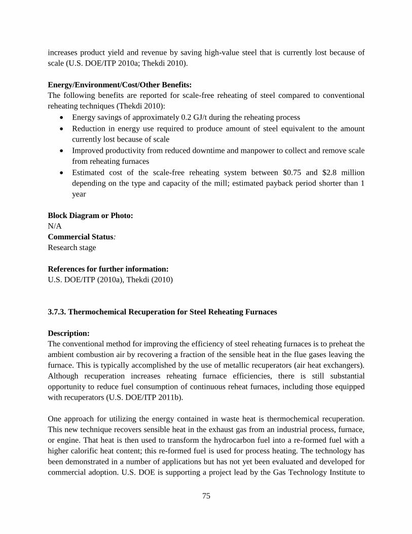
75
increases product yield and revenue by saving high-value steel that is currently lost because of
scale (U.S. DOE/ITP 2010a; Thekdi 2010).
Energy/Environment/Cost/Other Benefits:
The following benefits are reported for scale-free reheating of steel compared to conventional
reheating techniques (Thekdi 2010):
Energy savings of approximately 0.2 GJ/t during the reheating process
Reduction in energy use required to produce amount of steel equivalent to the amount
currently lost because of scale
Improved productivity from reduced downtime and manpower to collect and remove scale
from reheating furnaces
Estimated cost of the scale-free reheating system between $0.75 and $2.8 million
depending on the type and capacity of the mill; estimated payback period shorter than 1
year
Block Diagram or Photo:
N/A
Commercial Status:
Research stage
References for further information:
U.S. DOE/ITP (2010a), Thekdi (2010)
3.7.3. Thermochemical Recuperation for Steel Reheating Furnaces
Description:
The conventional method for improving the efficiency of steel reheating furnaces is to preheat the
ambient combustion air by recovering a fraction of the sensible heat in the flue gases leaving the
furnace. This is typically accomplished by the use of metallic recuperators (air heat exchangers).
Although recuperation increases reheating furnace efficiencies, there is still substantial
opportunity to reduce fuel consumption of continuous reheat furnaces, including those equipped
with recuperators (U.S. DOE/ITP 2011b).
One approach for utilizing the energy contained in waste heat is thermochemical recuperation.
This new technique recovers sensible heat in the exhaust gas from an industrial process, furnace,
or engine. That heat is then used to transform the hydrocarbon fuel into a re-formed fuel with a
higher calorific heat content; this re-formed fuel is used for process heating. The technology has
been demonstrated in a number of applications but has not yet been evaluated and developed for
commercial adoption. U.S. DOE is supporting a project lead by the Gas Technology Institute to
76
validate the technical feasibility of the thermochemical recuperation concept as well as its
business viability, including identification of technical, scale-up, and processing concerns (U.S.
DOE/ITP 2011b).
In the first phase of the project, the Gas Technology Institute licensed simulation software that
can model heat transfer and chemical reactions along with computational fluid dynamics. The
evaluation focused on energy-efficiency improvements and cost benefits. Technical information
developed during the first phase is being used to design, fabricate, and iteratively evaluate
performance metrics in a bench-scale thermochemical recuperation unit at the Gas Technology
Institute’s combustion laboratory. The results will then be used for engineering design, construc-
tion, and retrofitting of a full-scale thermochemical recuperation system for prototype field tests
on a steel reheating furnace (U.S. DOE/ITP 2011b).
Figure 38 shows a drawing of the thermochemical recuperation concept.
Energy/Environment/Cost/Other Benefits:
The following potential benefits could be achieved by thermochemical recuperation compared to
conventional reheating techniques (U.S. DOE/ITP 2011b):
Net reduction in continuous reheating furnace fuel use because the energy content of the
fuel can be increased by more than 25 percent when the original source fuel is natural gas
Proportional reduction in CO2 emissions
Reduced NOx emissions
Block Diagram or Photo:
Figure 38. Thermochemical recuperation concept (U.S. DOE/ITP 2011b)
Commercial Status:
Research stage
Reference for further information:
U.S. DOE/ITP (2011b)
77
3.7.4. Hot Strip Mill Model
Description:
Steel from the continuous caster ranges from 1 to 25 centimeters thick. Steel is further reduced in
thickness in hot and cold rolling operations. Steel products from the caster are themselves highly
valuable; well over 50 percent of the cost of materials and energy is contained in these semi-
finished products. Failure during the rolling operation can result in the scrapping or downgrading
of this valuable commodity. During rolling, the steel undergoes numerous heating and gauging
operations. This thermo-mechanical processing is as much responsible for the final properties of
the steel as is its chemical composition. Furthermore, the steel produced must adhere to rigorous
dimensional tolerances to satisfy the needs of the customer’s forming operations. Often the “trial
and error” rolling of many tons of steel is necessary to develop proper rolling practice for a given
product. This is not only costly, but it also removes the rolling mill from commercial service,
resulting in the loss of saleable products. To address these issues, the DOE/AISI Advanced
Process Control program and TR Program supported the development of the hot strip mill model
by the University of Bristish Columbia and INTEG Process Group, Inc. (AISI 2010).
The hot strip mill model is an off-line PC-based software model originally developed by the
University of British Columbia and the National Institute of Standards and Technology
(Shulkosky et al. 2005). The model predicts the temperatures, deformation, microstructural
evolution, and mechanical properties of steel strip or plate rolled on a hot mill. The model can be
used to help locate the source of flaws introduced during rolling, to develop new rolling practices
and products, and to improve existing rolling operations. It has been licensed to INTEG
Corporation, which has subsequently adapted and resold the model to 32 steel mills (AISI 2010).
Users can set up their mill configurations, including number of reheat furnaces, roughing mill
stands, heat retention equipment, finishing mill stands, run-out table cooling system, and mill exit
area. The model can handle both strip and plate and can be configured for reversing mills,
continuous mills, tandem mills, or Steckel mills utilizing a coiler or cooling bed. A variety of
steel grades can be handled, including material characteristics for basic carbon grades, high-
strength low-alloy grades and interstitial free grades. Dual-phase steels are being added (INTEG
process group, Inc. 2004).
The hot strip mill model can be used for a variety of applications. Current users have employed it
to study mill configurations, rolling schedules, and process parameters to gain detailed insight
into their operations that are not available with their current models and control systems (e.g.,
information on temperature distribution, transformation start temperatures, and final mechanical
properties) (INTEG process group, Inc. 2004).
Figure 39 shows the hot strip mill model structure.
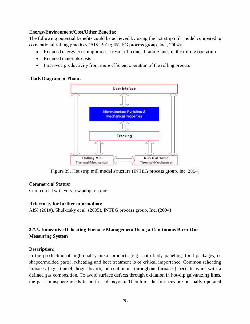
78
Energy/Environment/Cost/Other Benefits:
The following potential benefits could be achieved by using the hot strip mill model compared to
conventional rolling practices (AISI 2010; INTEG process group, Inc., 2004):
Reduced energy consumption as a result of reduced failure rates in the rolling operation
Reduced materials costs
Improved productivity from more efficient operation of the rolling process
Block Diagram or Photo:
Figure 39. Hot strip mill model structure (INTEG process group, Inc. 2004)
Commercial Status:
Commercial with very low adoption rate
References for further information:
AISI (2010), Shulkosky et al. (2005), INTEG process group, Inc. (2004)
3.7.5. Innovative Reheating Furnace Management Using a Continuous Burn-Out
Measuring System
Description:
In the production of high-quality metal products (e.g., auto body paneling, food packages, or
shaped/molded parts), reheating and heat treatment is of critical importance. Common reheating
furnaces (e.g., tunnel, bogie hearth, or continuous-throughput furnaces) need to work with a
defined gas composition. To avoid surface defects through oxidation in hot-dip galvanizing lines,
the gas atmosphere needs to be free of oxygen. Therefore, the furnaces are normally operated
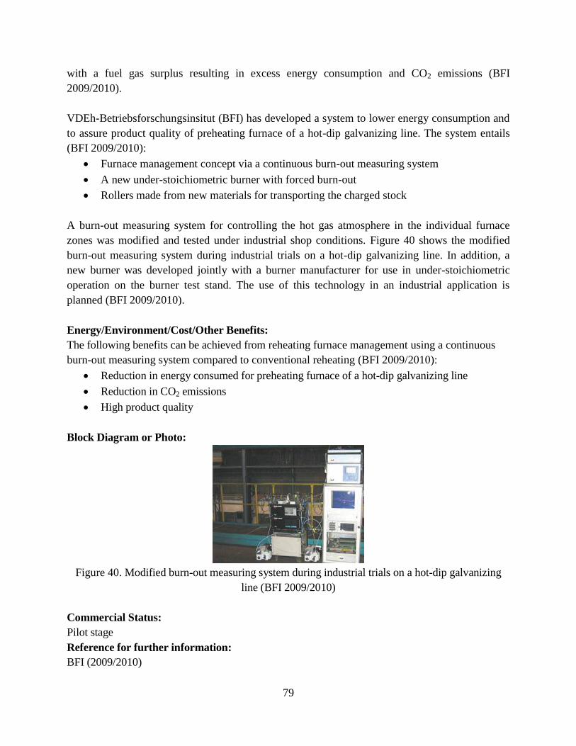
79
with a fuel gas surplus resulting in excess energy consumption and CO2 emissions (BFI
2009/2010).
VDEh-Betriebsforschungsinsitut (BFI) has developed a system to lower energy consumption and
to assure product quality of preheating furnace of a hot-dip galvanizing line. The system entails
(BFI 2009/2010):
Furnace management concept via a continuous burn-out measuring system
A new under-stoichiometric burner with forced burn-out
Rollers made from new materials for transporting the charged stock
A burn-out measuring system for controlling the hot gas atmosphere in the individual furnace
zones was modified and tested under industrial shop conditions. Figure 40 shows the modified
burn-out measuring system during industrial trials on a hot-dip galvanizing line. In addition, a
new burner was developed jointly with a burner manufacturer for use in under-stoichiometric
operation on the burner test stand. The use of this technology in an industrial application is
planned (BFI 2009/2010).
Energy/Environment/Cost/Other Benefits:
The following benefits can be achieved from reheating furnace management using a continuous
burn-out measuring system compared to conventional reheating (BFI 2009/2010):
Reduction in energy consumed for preheating furnace of a hot-dip galvanizing line
Reduction in CO2 emissions
High product quality
Block Diagram or Photo:
Figure 40. Modified burn-out measuring system during industrial trials on a hot-dip galvanizing
line (BFI 2009/2010)
Commercial Status:
Pilot stage
Reference for further information:
BFI (2009/2010)
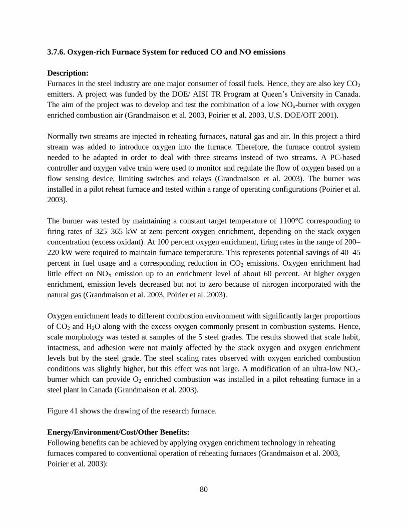
80
3.7.6. Oxygen-rich Furnace System for reduced CO and NO emissions
Description:
Furnaces in the steel industry are one major consumer of fossil fuels. Hence, they are also key CO2
emitters. A project was funded by the DOE/ AISI TR Program at Queen’s University in Canada.
The aim of the project was to develop and test the combination of a low NOx-burner with oxygen
enriched combustion air (Grandmaison et al. 2003, Poirier et al. 2003, U.S. DOE/OIT 2001).
Normally two streams are injected in reheating furnaces, natural gas and air. In this project a third
stream was added to introduce oxygen into the furnace. Therefore, the furnace control system
needed to be adapted in order to deal with three streams instead of two streams. A PC-based
controller and oxygen valve train were used to monitor and regulate the flow of oxygen based on a
flow sensing device, limiting switches and relays (Grandmaison et al. 2003). The burner was
installed in a pilot reheat furnace and tested within a range of operating configurations (Poirier et al.
2003).
The burner was tested by maintaining a constant target temperature of 1100°C corresponding to
firing rates of 325–365 kW at zero percent oxygen enrichment, depending on the stack oxygen
concentration (excess oxidant). At 100 percent oxygen enrichment, firing rates in the range of 200–
220 kW were required to maintain furnace temperature. This represents potential savings of 40–45
percent in fuel usage and a corresponding reduction in CO2 emissions. Oxygen enrichment had
little effect on NOX emission up to an enrichment level of about 60 percent. At higher oxygen
enrichment, emission levels decreased but not to zero because of nitrogen incorporated with the
natural gas (Grandmaison et al. 2003, Poirier et al. 2003).
Oxygen enrichment leads to different combustion environment with significantly larger proportions
of CO2 and H2O along with the excess oxygen commonly present in combustion systems. Hence,
scale morphology was tested at samples of the 5 steel grades. The results showed that scale habit,
intactness, and adhesion were not mainly affected by the stack oxygen and oxygen enrichment
levels but by the steel grade. The steel scaling rates observed with oxygen enriched combustion
conditions was slightly higher, but this effect was not large. A modification of an ultra-low NOx-
burner which can provide O2 enriched combustion was installed in a pilot reheating furnace in a
steel plant in Canada (Grandmaison et al. 2003).
Figure 41 shows the drawing of the research furnace.
Energy/Environment/Cost/Other Benefits:
Following benefits can be achieved by applying oxygen enrichment technology in reheating
furnaces compared to conventional operation of reheating furnaces (Grandmaison et al. 2003,
Poirier et al. 2003):
81
Potential savings of 40–45 percent in fuel usage and a corresponding reduction in CO2
emissions
Reduced NOx emissions
Block Diagram or Photo:
Figure 41. Drawing of the research furnace showing the location of the specimen ports, S1 --- S4,
and roof thermocouples, T1 --- T3, adjacent to the ports (Grandmaison et al. 2003)
Commercial Status:
Developmental stage
Reference for further information:
Grandmaison et al. (2003), Poirier et al. (2003), U.S. DOE/OIT (2001)
3.7.7. HotEye® Steel Surface Inspection System
Description:
A new inspection system, the HotEye® Rolled Steel Bar (RSB) System, has been developed and
demonstrated by OG Technologies Inc. The system integrates OG Technologies’ HotEye with a
dynamic control plan for hot steel processes, mainly rolling. The HotEye system accurately and
reliably measures a part’s dimensions and detects its surface features, including defects, while the
part is still red hot, i.e., at temperatures of up to 1,550°C. This enables defects to be corrected
before the part cools, an advantage over current measurement systems, which cannot be used
until parts cool, resulting in higher scrap rates when defects are detected. The dynamic control
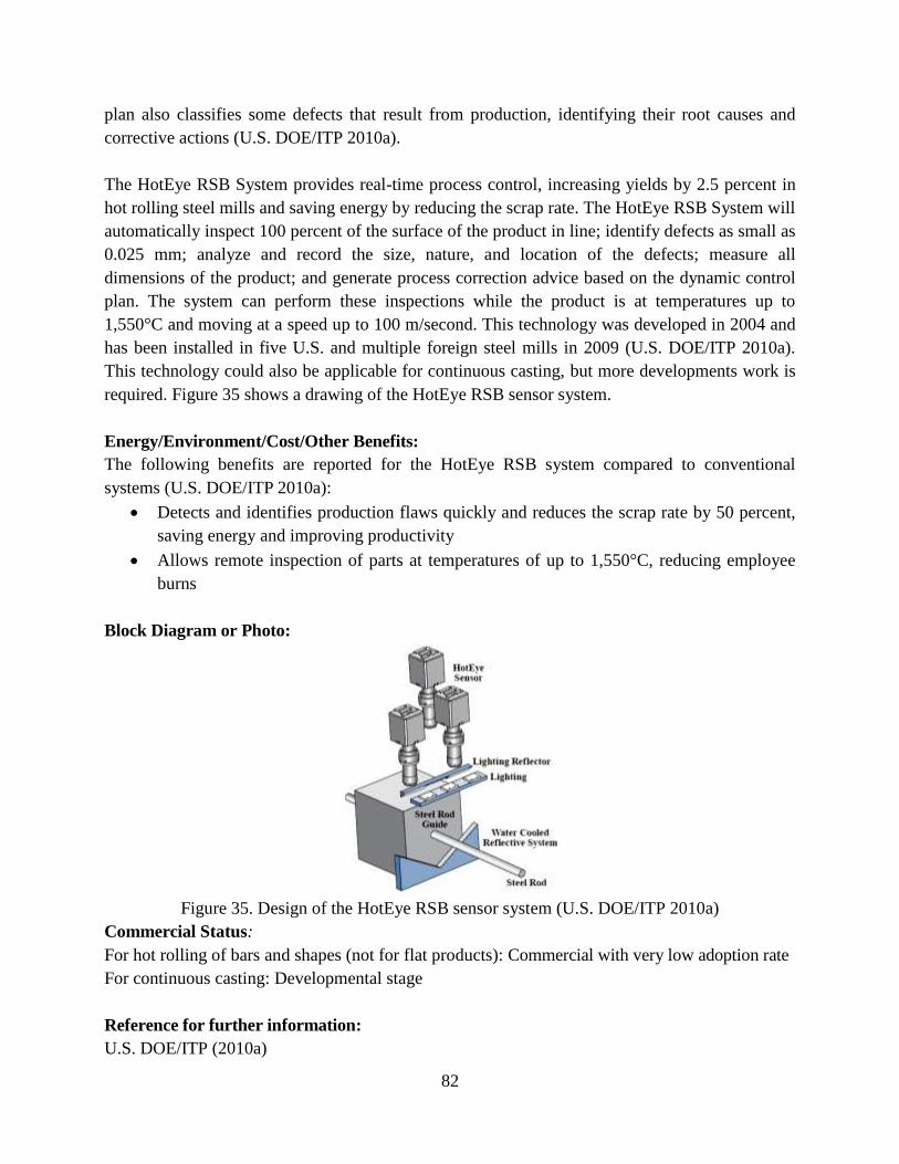
82
plan also classifies some defects that result from production, identifying their root causes and
corrective actions (U.S. DOE/ITP 2010a).
The HotEye RSB System provides real-time process control, increasing yields by 2.5 percent in
hot rolling steel mills and saving energy by reducing the scrap rate. The HotEye RSB System will
automatically inspect 100 percent of the surface of the product in line; identify defects as small as
0.025 mm; analyze and record the size, nature, and location of the defects; measure all
dimensions of the product; and generate process correction advice based on the dynamic control
plan. The system can perform these inspections while the product is at temperatures up to
1,550°C and moving at a speed up to 100 m/second. This technology was developed in 2004 and
has been installed in five U.S. and multiple foreign steel mills in 2009 (U.S. DOE/ITP 2010a).
This technology could also be applicable for continuous casting, but more developments work is
required. Figure 35 shows a drawing of the HotEye RSB sensor system.
Energy/Environment/Cost/Other Benefits:
The following benefits are reported for the HotEye RSB system compared to conventional
systems (U.S. DOE/ITP 2010a):
Detects and identifies production flaws quickly and reduces the scrap rate by 50 percent,
saving energy and improving productivity
Allows remote inspection of parts at temperatures of up to 1,550°C, reducing employee
burns
Block Diagram or Photo:
Figure 35. Design of the HotEye RSB sensor system (U.S. DOE/ITP 2010a)
Commercial Status:
For hot rolling of bars and shapes (not for flat products): Commercial with very low adoption rate
For continuous casting: Developmental stage
Reference for further information:
U.S. DOE/ITP (2010a)
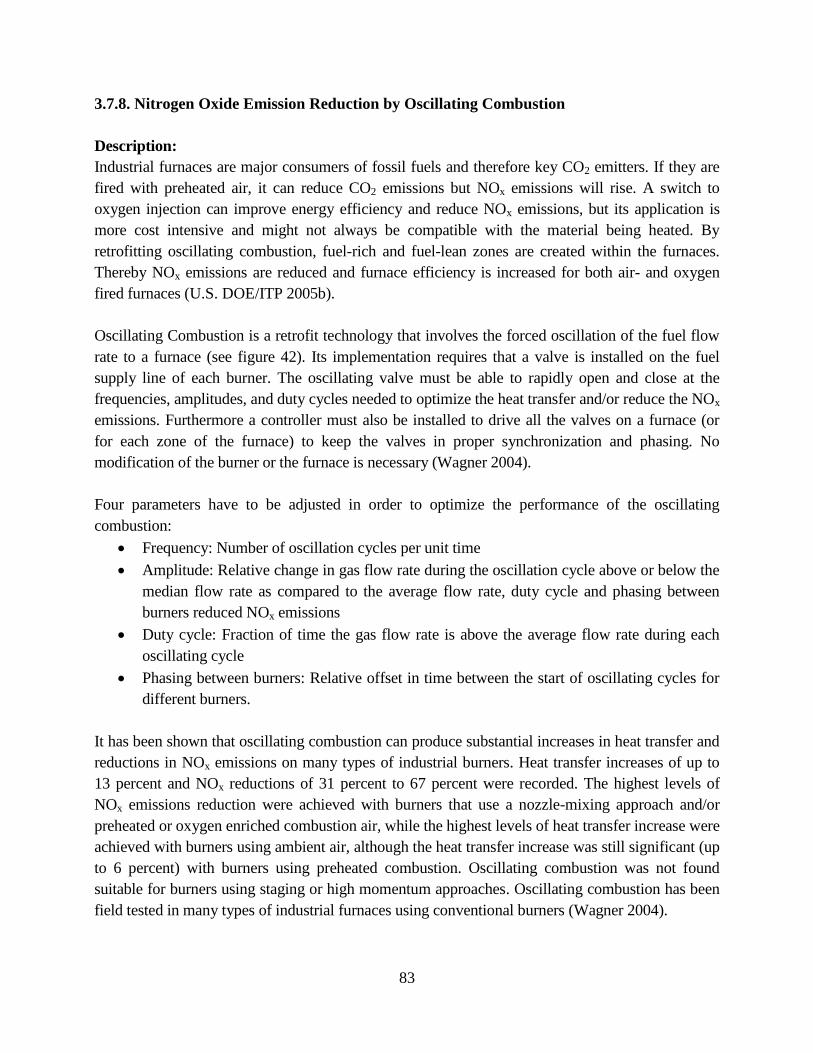
83
3.7.8. Nitrogen Oxide Emission Reduction by Oscillating Combustion
Description:
Industrial furnaces are major consumers of fossil fuels and therefore key CO2 emitters. If they are
fired with preheated air, it can reduce CO2 emissions but NOx emissions will rise. A switch to
oxygen injection can improve energy efficiency and reduce NOx emissions, but its application is
more cost intensive and might not always be compatible with the material being heated. By
retrofitting oscillating combustion, fuel-rich and fuel-lean zones are created within the furnaces.
Thereby NOx emissions are reduced and furnace efficiency is increased for both air- and oxygen
fired furnaces (U.S. DOE/ITP 2005b).
Oscillating Combustion is a retrofit technology that involves the forced oscillation of the fuel flow
rate to a furnace (see figure 42). Its implementation requires that a valve is installed on the fuel
supply line of each burner. The oscillating valve must be able to rapidly open and close at the
frequencies, amplitudes, and duty cycles needed to optimize the heat transfer and/or reduce the NOx
emissions. Furthermore a controller must also be installed to drive all the valves on a furnace (or
for each zone of the furnace) to keep the valves in proper synchronization and phasing. No
modification of the burner or the furnace is necessary (Wagner 2004).
Four parameters have to be adjusted in order to optimize the performance of the oscillating
combustion:
Frequency: Number of oscillation cycles per unit time
Amplitude: Relative change in gas flow rate during the oscillation cycle above or below the
median flow rate as compared to the average flow rate, duty cycle and phasing between
burners reduced NOx emissions
Duty cycle: Fraction of time the gas flow rate is above the average flow rate during each
oscillating cycle
Phasing between burners: Relative offset in time between the start of oscillating cycles for
different burners.
It has been shown that oscillating combustion can produce substantial increases in heat transfer and
reductions in NOx emissions on many types of industrial burners. Heat transfer increases of up to
13 percent and NOx reductions of 31 percent to 67 percent were recorded. The highest levels of
NOx emissions reduction were achieved with burners that use a nozzle-mixing approach and/or
preheated or oxygen enriched combustion air, while the highest levels of heat transfer increase were
achieved with burners using ambient air, although the heat transfer increase was still significant (up
to 6 percent) with burners using preheated combustion. Oscillating combustion was not found
suitable for burners using staging or high momentum approaches. Oscillating combustion has been
field tested in many types of industrial furnaces using conventional burners (Wagner 2004).
84
Figure 42 shows the oscillating combustion concept.
Energy/Environment/Cost/Other Benefits:
Following benefits can be achieved by applying oscillating combustion (Wagner 2004, U.S.
DOE/OIT 2001b, U.S. DOE/ITP 2005b):
Saving of up to 5 percent of fuel use by the furnace
Improved heat transfer by up to 13 percent
Increased productivity by 5 percent or more
Reduced NOx emissions by up to 75 percent
Simple retrofit that does not require modification of burner or furnace
Block Diagram or Photo:
Figure 42. Oscillating combustion concept (Wagner 2004)
Commercial Status:
Pilot stage
Reference for further information:
Wagner (2004), U.S. DOE/OIT (2001b), U.S. DOE/ITP (2005b)
85
3.8. Emerging Recycling and Waste Reduction Technologies
The subsections below describe the following recycling and waste reduction technologies to
reduce energy use and CO2 emissions by the steel industry: BOF slag recycling, dust recycling
for RHFs, recycling stainless steel dust by injection into EAFs, regeneration of hydrochloric acid
pickling liquor, and recycling of waste oxides.
3.8.1. Recycling Basic Oxygen Furnace Slag
Description:
The U.S. steel industry generates about 30 million tonnes of byproducts each year, including 6
million tonnes of BOF/basic oxygen process slag. The recycling of BF slag has made significant
progress, with much of the material being utilized as construction aggregate and in cementitious
applications. However, the recycling of BOF/ basic oxygen process slag still faces many
technical, economic, and environmental challenges. Previous efforts have focused on in-plant
recycling of byproducts and have achieved limited success. As a result, large amounts of
byproducts of various qualities have been stockpiled at steel mills or disposed of at landfills.
However, available mill site space has diminished, and environmental constraints on disposal
have increased (IMP/MTU 2006).
With support from U.S. DOE, Michigan Technological University has developed an integrated
system of technologies to recover the iron value from BOF steelmaking slag and to divert the
residual non-iron bearing fraction into a feedstock for the manufacture of an acid mine drainage
neutralizing agent (U.S. DOE/OIT 2002).
Three products are generated from the technology developed through this research: a high-grade
iron product containing about 90-percent iron, a medium-grade iron product containing about 60-
percent iron, and a low-grade iron product containing less than 10-percent iron. The high-grade
iron product contains primarily metallic iron and can be marketed as a replacement for pig iron or
DRI for steel mills. The medium-grade iron product contains both iron oxide and metallic iron
and can be utilized as a substitute for iron ore in the BF. The low-grade iron product is rich in
calcium, magnesium, iron oxides, and silicates. It has sufficient lime value to be utilized for acid
mine drainage treatment.
Analysis indicates that the economics of the technology are favorable. ICAN Global obtained a
license agreement for the technology. This right was later transferred to the Westwood Land, Inc.
A demonstration pilot plant was constructed to evaluate the technology (IMP/MTU 2006).
JFE Steel Group in Japan has also developed a new product from steelmaking slag: a large
carbonated slag block called the “marine block.” The marine block is intended to serve as
substratum for seaweed, for improving coastline and coastal marine environments. The marine
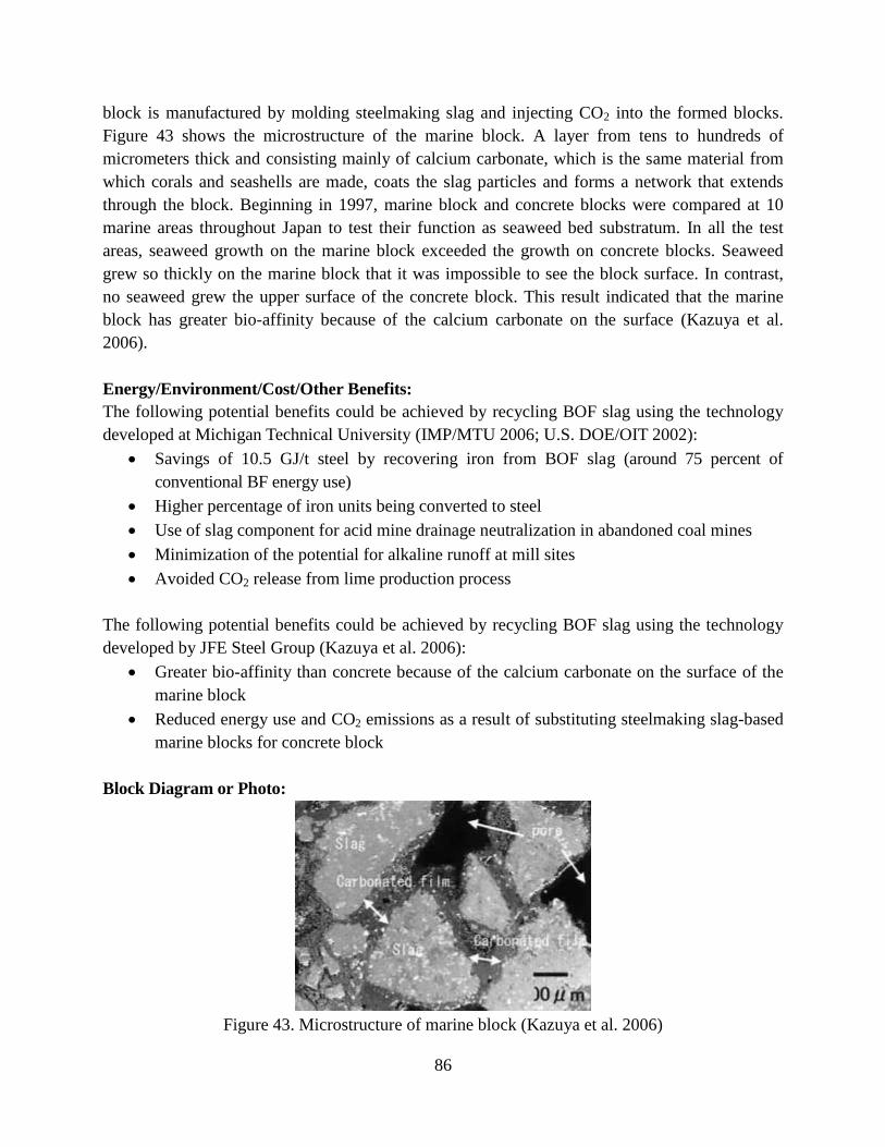
86
block is manufactured by molding steelmaking slag and injecting CO2 into the formed blocks.
Figure 43 shows the microstructure of the marine block. A layer from tens to hundreds of
micrometers thick and consisting mainly of calcium carbonate, which is the same material from
which corals and seashells are made, coats the slag particles and forms a network that extends
through the block. Beginning in 1997, marine block and concrete blocks were compared at 10
marine areas throughout Japan to test their function as seaweed bed substratum. In all the test
areas, seaweed growth on the marine block exceeded the growth on concrete blocks. Seaweed
grew so thickly on the marine block that it was impossible to see the block surface. In contrast,
no seaweed grew the upper surface of the concrete block. This result indicated that the marine
block has greater bio-affinity because of the calcium carbonate on the surface (Kazuya et al.
2006).
Energy/Environment/Cost/Other Benefits:
The following potential benefits could be achieved by recycling BOF slag using the technology
developed at Michigan Technical University (IMP/MTU 2006; U.S. DOE/OIT 2002):
Savings of 10.5 GJ/t steel by recovering iron from BOF slag (around 75 percent of
conventional BF energy use)
Higher percentage of iron units being converted to steel
Use of slag component for acid mine drainage neutralization in abandoned coal mines
Minimization of the potential for alkaline runoff at mill sites
Avoided CO2 release from lime production process
The following potential benefits could be achieved by recycling BOF slag using the technology
developed by JFE Steel Group (Kazuya et al. 2006):
Greater bio-affinity than concrete because of the calcium carbonate on the surface of the
marine block
Reduced energy use and CO2 emissions as a result of substituting steelmaking slag-based
marine blocks for concrete block
Block Diagram or Photo:
Figure 43. Microstructure of marine block (Kazuya et al. 2006)
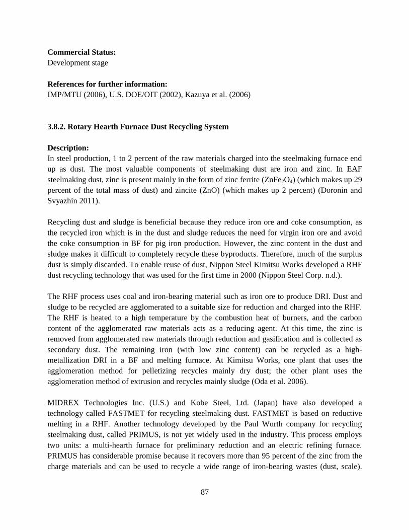
87
Commercial Status:
Development stage
References for further information:
IMP/MTU (2006), U.S. DOE/OIT (2002), Kazuya et al. (2006)
3.8.2. Rotary Hearth Furnace Dust Recycling System
Description:
In steel production, 1 to 2 percent of the raw materials charged into the steelmaking furnace end
up as dust. The most valuable components of steelmaking dust are iron and zinc. In EAF
steelmaking dust, zinc is present mainly in the form of zinc ferrite (ZnFe2O4) (which makes up 29
percent of the total mass of dust) and zincite (ZnO) (which makes up 2 percent) (Doronin and
Svyazhin 2011).
Recycling dust and sludge is beneficial because they reduce iron ore and coke consumption, as
the recycled iron which is in the dust and sludge reduces the need for virgin iron ore and avoid
the coke consumption in BF for pig iron production. However, the zinc content in the dust and
sludge makes it difficult to completely recycle these byproducts. Therefore, much of the surplus
dust is simply discarded. To enable reuse of dust, Nippon Steel Kimitsu Works developed a RHF
dust recycling technology that was used for the first time in 2000 (Nippon Steel Corp. n.d.).
The RHF process uses coal and iron-bearing material such as iron ore to produce DRI. Dust and
sludge to be recycled are agglomerated to a suitable size for reduction and charged into the RHF.
The RHF is heated to a high temperature by the combustion heat of burners, and the carbon
content of the agglomerated raw materials acts as a reducing agent. At this time, the zinc is
removed from agglomerated raw materials through reduction and gasification and is collected as
secondary dust. The remaining iron (with low zinc content) can be recycled as a high-
metallization DRI in a BF and melting furnace. At Kimitsu Works, one plant that uses the
agglomeration method for pelletizing recycles mainly dry dust; the other plant uses the
agglomeration method of extrusion and recycles mainly sludge (Oda et al. 2006).
MIDREX Technologies Inc. (U.S.) and Kobe Steel, Ltd. (Japan) have also developed a
technology called FASTMET for recycling steelmaking dust. FASTMET is based on reductive
melting in a RHF. Another technology developed by the Paul Wurth company for recycling
steelmaking dust, called PRIMUS, is not yet widely used in the industry. This process employs
two units: a multi-hearth furnace for preliminary reduction and an electric refining furnace.
PRIMUS has considerable promise because it recovers more than 95 percent of the zinc from the
charge materials and can be used to recycle a wide range of iron-bearing wastes (dust, scale).
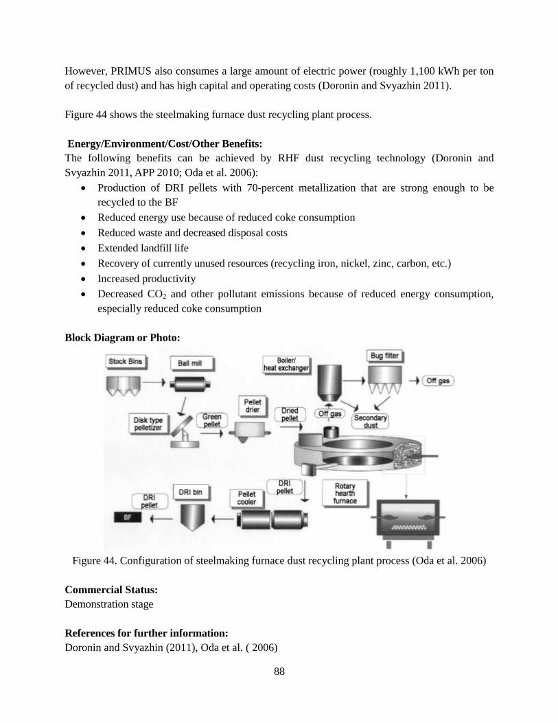
88
However, PRIMUS also consumes a large amount of electric power (roughly 1,100 kWh per ton
of recycled dust) and has high capital and operating costs (Doronin and Svyazhin 2011).
Figure 44 shows the steelmaking furnace dust recycling plant process.
Energy/Environment/Cost/Other Benefits:
The following benefits can be achieved by RHF dust recycling technology (Doronin and
Svyazhin 2011, APP 2010; Oda et al. 2006):
Production of DRI pellets with 70-percent metallization that are strong enough to be
recycled to the BF
Reduced energy use because of reduced coke consumption
Reduced waste and decreased disposal costs
Extended landfill life
Recovery of currently unused resources (recycling iron, nickel, zinc, carbon, etc.)
Increased productivity
Decreased CO2 and other pollutant emissions because of reduced energy consumption,
especially reduced coke consumption
Block Diagram or Photo:
Figure 44. Configuration of steelmaking furnace dust recycling plant process (Oda et al. 2006)
Commercial Status:
Demonstration stage
References for further information:
Doronin and Svyazhin (2011), Oda et al. ( 2006)
89
3.8.3. Recycling of Stainless Steel Dust by Injection into Electric Arc Furnace
Description:
In EAF steelmaking valuable amounts of material is usually lost in the by-product dust. The dust
normally consists of oxides of iron, zinc and chromium, but its content varies depending of the
scrap input. The recycling of stainless steel dust by re-injection into the EAF is one opportunity for
energy efficiency improvement in steelmaking.
A pilot plants project on the injection of stainless steel dust into the EAF was funded by the
European Commission (Directorate-General Science, Research and Development). Tests were
conducted at Ugine-Savoie Imphy at Ugine (USI), France, and Krupp Edelstahlprofile (KEP),
Germany (Travernier et al. 2004). In a first step of the project, the analysis procedure for stainless
steel dust was validated using dust from USI and KEP. The analysis method was proved
concerning the following parameters: amount of dust, emissions flow rate, and composition
(Travernier et al. 2004).
Key feature of the process is the pneumatic injection of steelmaking dust into the EAF. To allow a
stable process the dust was co-injected with carbon and/or with ferro-silicon (FeSi) at KEP, or
blended with coke at USI. It was shown that the recycling of the dust with this process does not
alter the produced slag (Travernier et al. 2004).
Energy/Environment/Cost/Other Benefits:
Following benefits are reported that can be achieved by recycling stainless steel dust in EAFs
(Travernier et al. 2004, EIPPCB 2009):
Use of ferro-silicon as a further reducing agent allowed reaching recovery ratio of 81
percent, 38 percent, 97 percent and 93 percent for Cr, Mn, Ni and Fe, respectively
Annual operating costs can be reduced by 9 percent
Block Diagram or Photo:
Not available
Commercial Status:
Pilot stage
Reference for further information:
Travernier et al. (2004), EIPPCB (2009)
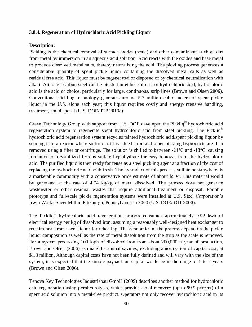
90
3.8.4. Regeneration of Hydrochloric Acid Pickling Liquor
Description:
Pickling is the chemical removal of surface oxides (scale) and other contaminants such as dirt
from metal by immersion in an aqueous acid solution. Acid reacts with the oxides and base metal
to produce dissolved metal salts, thereby neutralizing the acid. The pickling process generates a
considerable quantity of spent pickle liquor containing the dissolved metal salts as well as
residual free acid. This liquor must be regenerated or disposed of by chemical neutralization with
alkali. Although carbon steel can be pickled in either sulfuric or hydrochloric acid, hydrochloric
acid is the acid of choice, particularly for large, continuous, strip lines (Brown and Olsen 2006).
Conventional pickling technology generates around 5.7 million cubic meters of spent pickle
liquor in the U.S. alone each year; this liquor requires costly and energy-intensive handling,
treatment, and disposal (U.S. DOE/ ITP 2010a).
Green Technology Group with support from U.S. DOE developed the Pickliq® hydrochloric acid
regeneration system to regenerate spent hydrochloric acid from steel pickling. The Pickliq®
hydrochloric acid regeneration system recycles tainted hydrochloric acid/spent pickling liquor by
sending it to a reactor where sulfuric acid is added. Iron and other pickling byproducts are then
removed using a filter or centrifuge. The solution is chilled to between -24°C and -18°C, causing
formation of crystallized ferrous sulfate heptahydrate for easy removal from the hydrochloric
acid. The purified liquid is then ready for reuse as a steel pickling agent at a fraction of the cost of
replacing the hydrochloric acid with fresh. The byproduct of this process, sulfate heptahydrate, is
a marketable commodity with a conservative price estimate of about $50/t. This material would
be generated at the rate of 4.74 kg/kg of metal dissolved. The process does not generate
wastewater or other residual wastes that require additional treatment or disposal. Portable
prototype and full-scale pickle regeneration systems were installed at U.S. Steel Corporation’s
Irwin Works Sheet Mill in Pittsburgh, Pennsylvania in 2000 (U.S. DOE/ OIT 2000).
The Pickliq® hydrochloric acid regeneration process consumes approximately 0.92 kwh of
electrical energy per kg of dissolved iron, assuming a reasonably well-designed heat exchanger to
reclaim heat from spent liquor for reheating. The economics of the process depend on the pickle
liquor composition as well as the rate of metal dissolution from the strip as the scale is removed.
For a system processing 100 kg/h of dissolved iron from about 200,000 t/ year of production,
Brown and Olsen (2006) estimate the annual savings, excluding amortization of capital cost, at
$1.3 million. Although capital costs have not been fully defined and will vary with the size of the
system, it is expected that the simple payback on capital would be in the range of 1 to 2 years
(Brown and Olsen 2006).
Tenova Key Technologies Industriebau GmbH (2009) describes another method for hydrochloric
acid regeneration using pyrohydrolysis, which provides total recovery (up to 99.9 percent) of a
spent acid solution into a metal-free product. Operators not only recover hydrochloric acid in its
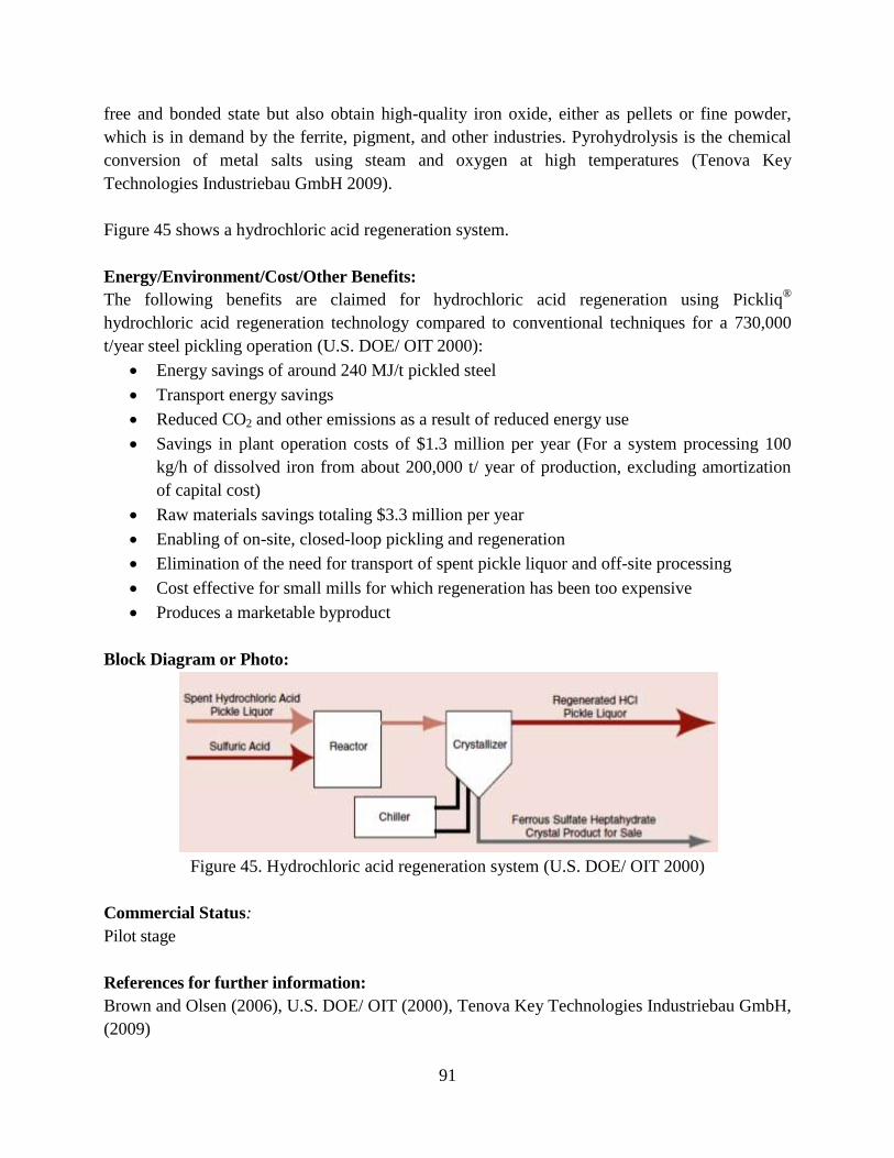
91
free and bonded state but also obtain high-quality iron oxide, either as pellets or fine powder,
which is in demand by the ferrite, pigment, and other industries. Pyrohydrolysis is the chemical
conversion of metal salts using steam and oxygen at high temperatures (Tenova Key
Technologies Industriebau GmbH 2009).
Figure 45 shows a hydrochloric acid regeneration system.
Energy/Environment/Cost/Other Benefits:
The following benefits are claimed for hydrochloric acid regeneration using Pickliq®
hydrochloric acid regeneration technology compared to conventional techniques for a 730,000
t/year steel pickling operation (U.S. DOE/ OIT 2000):
Energy savings of around 240 MJ/t pickled steel
Transport energy savings
Reduced CO2 and other emissions as a result of reduced energy use
Savings in plant operation costs of $1.3 million per year (For a system processing 100
kg/h of dissolved iron from about 200,000 t/ year of production, excluding amortization
of capital cost)
Raw materials savings totaling $3.3 million per year
Enabling of on-site, closed-loop pickling and regeneration
Elimination of the need for transport of spent pickle liquor and off-site processing
Cost effective for small mills for which regeneration has been too expensive
Produces a marketable byproduct
Block Diagram or Photo:
Figure 45. Hydrochloric acid regeneration system (U.S. DOE/ OIT 2000)
Commercial Status:
Pilot stage
References for further information:
Brown and Olsen (2006), U.S. DOE/ OIT (2000), Tenova Key Technologies Industriebau GmbH,
(2009)
92
3.8.5. Recycling of Waste Oxides in Steelmaking Furnace
Description:
Major sources of waste oxides originate from BF, BOF, EAF, and mill scale from rolling in the
form of waste oxide briquettes (WOBs). In most countries, BF and BOF dusts are recycled in sinter
plants and used in the BF. However, in the US, most sinter plants have been closed and
considerable amounts of dust are simply being land-filled (U.S. DOE 2001).
WOBs are often used in the BF. However, their use in the BF is limited because they soften at
lower temperatures than sinter or pellets causing an increased pressure drop in the furnace and thus
reducing productivity. They also cause excessive zinc build-up in the furnace, which can cause
scaffolding. WOBs can also be used in the BOF, but they reduce scrap melting, increase the zinc
content of the dust, and cause excessive slopping (U.S. DOE 2001).
Slopping is the critical issue when using WOBs. Plant trials were conducted by Carnegie Mellon
University in Pittsburgh, USA, in which the ferro-oxide (FeO) and basicity of the slag were
measured during the BOF process with and without WOB additions. Slopping occurs when there is
an increase in gas evolution into a highly foamable slag. Excessive gas generation occurs when
over-oxidized slag with high FeO contents reacts with carbon in iron drops producing carbon
monoxide (CO). High foamable slags are those with high viscosity. These slags have a low basicity
and temperature and are present in the first 50 percent of the blow when slopping occurs. It was
found that slopping is promoted at a critical FeO content in the slag when metal drops emulsify
increasing the reaction area and rate drastically. It was concluded to delay the build-up of FeO in
the slag to this critical value, thus reducing slopping (U.S. DOE 2001).
Energy/Environment/Cost/Other Benefits:
Following benefits can be achieved by recycling waste oxides in steelmaking furnaces (U.S. DOE
2001, AISI 2012, U.S. DOE/OIT 2001c):
Eliminating the need to landfill waste oxide
Recovery of iron units from the waste oxides
Reduction of operating costs by understanding the mechanism of slopping
Block Diagram or Photo:
Not available
Commercial Status:
Pilot stage
Reference for further information:
U.S. DOE (2001), AISI (2012), U.S. DOE/OIT (2001)
93
3.9. Carbon Capture and Storage Technologies for the Iron and Steel industry
In the iron and steel sector, the main sources of CO2 emissions are power production, iron ore
reduction in either a BF or a DRI plant, and coke and sinter production. Selection of carbon
capture equipment will depend on factors including CO2 capture rate, possible requirements for
secondary gas treatment, energy consumption, reliability, and operational and capital costs. The
BF production process can be equipped with CO2 capture. There are also several alternatives to
BF technology that have lower carbon emissions, including advanced smelting reduction
technologies, e.g., HIsarna and FINEX, and DRI technology. Research is under way to identify
the most energy-efficient capture technique for removing CO2 from the BF gas recycling system.
Biomass-based DRI processes are also under development and could become an important low-
carbon iron production pathway (IEA/UNIDO 2011).
Unlike in the power generation sector, in the steel industry much of the generation of CO2 is
related to the reduction of the iron oxides that constitute iron ore. Oxyfuel combustion and pre- or
post-combustion capture chemical looping do not mean much in a steel industry context where
there is neither combustion nor oxidation except very locally inside the reactors (Birat 2010).
ULCOS is currently the largest initiative to reduce CO2 emissions from the iron and steel industry,
including through the use of carbon capture and storage. ULCOS is funded roughly equally by
industry partners and the European Union. Despite the evidence of significant interest in carbon
capture and storage (CCS) in the iron and steel sector, no large scale demonstration plants have
yet been developed (UNIDO 2010).
The subsections below describe emerging CCS technologies for the iron and steel industry.
3.9.1. Top-Gas Recycling in Blast Furnaces, with Carbon Capture and Storage
Description:
Perhaps the most advanced potential CCS technology for the iron and steel sector is the top-gas
recycling BF (TGR-BF) (UNIDO 2010). The TGR-BF relies on separation of the off gases so
that the useful components can be recycled back into the furnace and used as reducing agents.
This reduces the amount of coke needed in the furnace. In addition, the concept of injecting
oxygen into the furnace instead of preheated air removes unwanted nitrogen from the off gas,
which will be rich in CO (40 to 50 percent by volume), facilitating CCS. To experimentally test
this concept, a gas separation plant was constructed next to LKAB's Experimental BF in Luleå,
Sweden. At the experimental BF, facilities were installed to operate with pure oxygen and with
re-injection of CO gas. The combination of the modified BF and the gas separation plant was
successfully tested in 2007. Plans are currently being developed to test this principle in a
commercial-scale BF (ULCOS 2012b; Kuramochi et al. 2011).
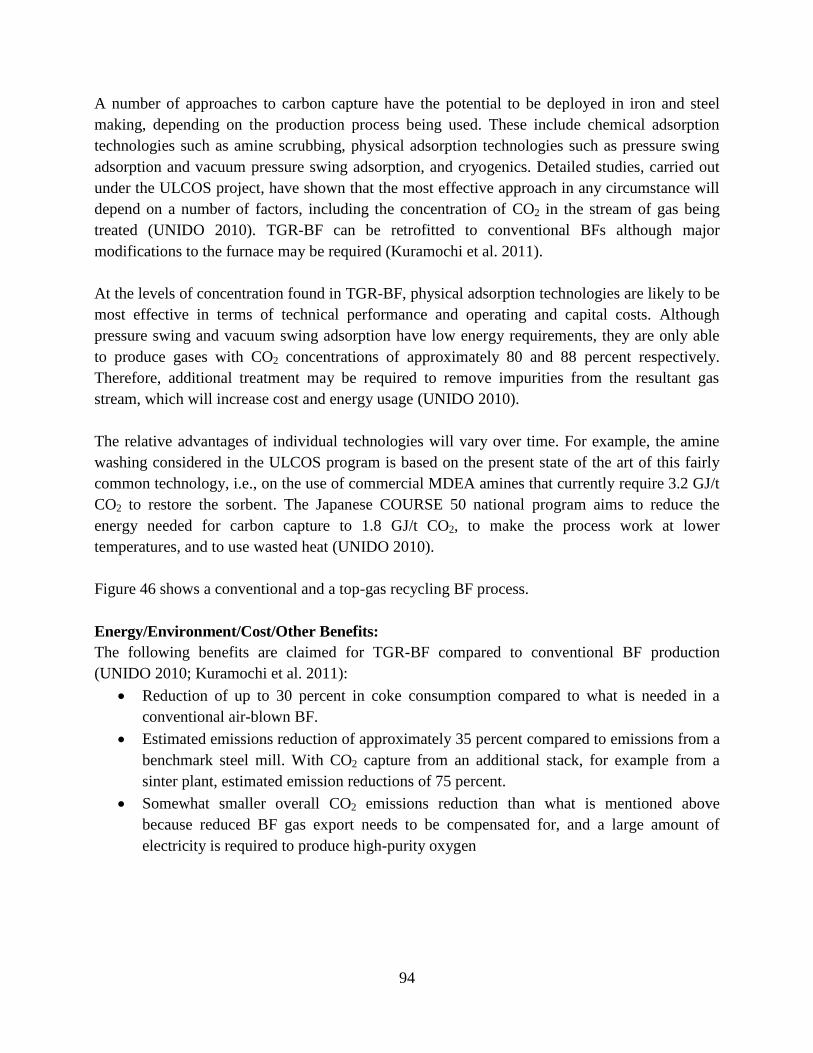
94
A number of approaches to carbon capture have the potential to be deployed in iron and steel
making, depending on the production process being used. These include chemical adsorption
technologies such as amine scrubbing, physical adsorption technologies such as pressure swing
adsorption and vacuum pressure swing adsorption, and cryogenics. Detailed studies, carried out
under the ULCOS project, have shown that the most effective approach in any circumstance will
depend on a number of factors, including the concentration of CO2 in the stream of gas being
treated (UNIDO 2010). TGR-BF can be retrofitted to conventional BFs although major
modifications to the furnace may be required (Kuramochi et al. 2011).
At the levels of concentration found in TGR-BF, physical adsorption technologies are likely to be
most effective in terms of technical performance and operating and capital costs. Although
pressure swing and vacuum swing adsorption have low energy requirements, they are only able
to produce gases with CO2 concentrations of approximately 80 and 88 percent respectively.
Therefore, additional treatment may be required to remove impurities from the resultant gas
stream, which will increase cost and energy usage (UNIDO 2010).
The relative advantages of individual technologies will vary over time. For example, the amine
washing considered in the ULCOS program is based on the present state of the art of this fairly
common technology, i.e., on the use of commercial MDEA amines that currently require 3.2 GJ/t
CO2 to restore the sorbent. The Japanese COURSE 50 national program aims to reduce the
energy needed for carbon capture to 1.8 GJ/t CO2, to make the process work at lower
temperatures, and to use wasted heat (UNIDO 2010).
Figure 46 shows a conventional and a top-gas recycling BF process.
Energy/Environment/Cost/Other Benefits:
The following benefits are claimed for TGR-BF compared to conventional BF production
(UNIDO 2010; Kuramochi et al. 2011):
Reduction of up to 30 percent in coke consumption compared to what is needed in a
conventional air-blown BF.
Estimated emissions reduction of approximately 35 percent compared to emissions from a
benchmark steel mill. With CO2 capture from an additional stack, for example from a
sinter plant, estimated emission reductions of 75 percent.
Somewhat smaller overall CO2 emissions reduction than what is mentioned above
because reduced BF gas export needs to be compensated for, and a large amount of
electricity is required to produce high-purity oxygen
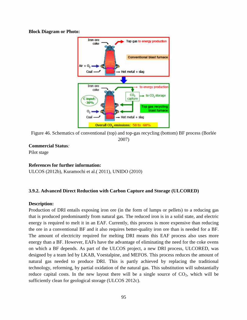
95
Block Diagram or Photo:
Figure 46. Schematics of conventional (top) and top-gas recycling (bottom) BF process (Borlée
2007)
Commercial Status:
Pilot stage
References for further information:
ULCOS (2012b), Kuramochi et al.( 2011), UNIDO (2010)
3.9.2. Advanced Direct Reduction with Carbon Capture and Storage (ULCORED)
Description:
Production of DRI entails exposing iron ore (in the form of lumps or pellets) to a reducing gas
that is produced predominantly from natural gas. The reduced iron is in a solid state, and electric
energy is required to melt it in an EAF. Currently, this process is more expensive than reducing
the ore in a conventional BF and it also requires better-quality iron ore than is needed for a BF.
The amount of electricity required for melting DRI means this EAF process also uses more
energy than a BF. However, EAFs have the advantage of eliminating the need for the coke ovens
on which a BF depends. As part of the ULCOS project, a new DRI process, ULCORED, was
designed by a team led by LKAB, Voestalpine, and MEFOS. This process reduces the amount of
natural gas needed to produce DRI. This is partly achieved by replacing the traditional
technology, reforming, by partial oxidation of the natural gas. This substitution will substantially
reduce capital costs. In the new layout there will be a single source of CO2, which will be
sufficiently clean for geological storage (ULCOS 2012c).
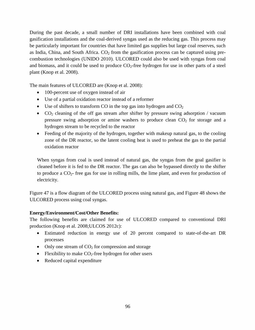
96
During the past decade, a small number of DRI installations have been combined with coal
gasification installations and the coal-derived syngas used as the reducing gas. This process may
be particularly important for countries that have limited gas supplies but large coal reserves, such
as India, China, and South Africa. CO2 from the gasification process can be captured using pre-
combustion technologies (UNIDO 2010). ULCORED could also be used with syngas from coal
and biomass, and it could be used to produce CO2-free hydrogen for use in other parts of a steel
plant (Knop et al. 2008).
The main features of ULCORED are (Knop et al. 2008):
100-percent use of oxygen instead of air
Use of a partial oxidation reactor instead of a reformer
Use of shifters to transform CO in the top gas into hydrogen and CO2
CO2 cleaning of the off gas stream after shifter by pressure swing adsorption / vacuum
pressure swing adsorption or amine washers to produce clean CO2 for storage and a
hydrogen stream to be recycled to the reactor
Feeding of the majority of the hydrogen, together with makeup natural gas, to the cooling
zone of the DR reactor, so the latent cooling heat is used to preheat the gas to the partial
oxidation reactor
When syngas from coal is used instead of natural gas, the syngas from the goal gasifier is
cleaned before it is fed to the DR reactor. The gas can also be bypassed directly to the shifter
to produce a CO2- free gas for use in rolling mills, the lime plant, and even for production of
electricity.
Figure 47 is a flow diagram of the ULCORED process using natural gas, and Figure 48 shows the
ULCORED process using coal syngas.
Energy/Environment/Cost/Other Benefits:
The following benefits are claimed for use of ULCORED compared to conventional DRI
production (Knop et al. 2008;ULCOS 2012c):
Estimated reduction in energy use of 20 percent compared to state-of-the-art DR
processes
Only one stream of CO2 for compression and storage
Flexibility to make CO2-free hydrogen for other users
Reduced capital expenditure
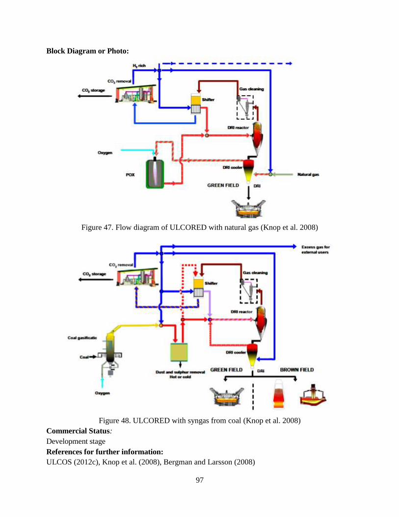
97
Block Diagram or Photo:
Figure 47. Flow diagram of ULCORED with natural gas (Knop et al. 2008)
Figure 48. ULCORED with syngas from coal (Knop et al. 2008)
Commercial Status:
Development stage
References for further information:
ULCOS (2012c), Knop et al. (2008), Bergman and Larsson (2008)
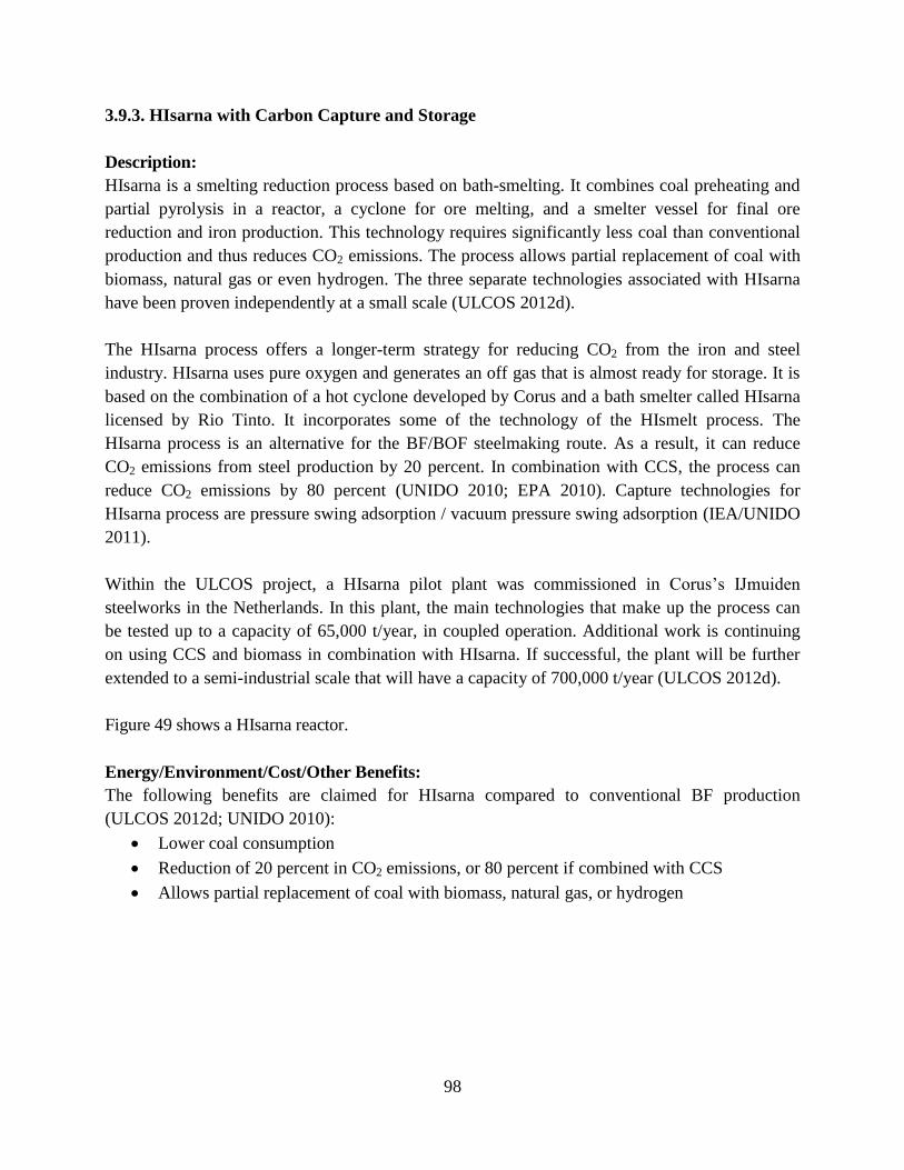
98
3.9.3. HIsarna with Carbon Capture and Storage
Description:
HIsarna is a smelting reduction process based on bath-smelting. It combines coal preheating and
partial pyrolysis in a reactor, a cyclone for ore melting, and a smelter vessel for final ore
reduction and iron production. This technology requires significantly less coal than conventional
production and thus reduces CO2 emissions. The process allows partial replacement of coal with
biomass, natural gas or even hydrogen. The three separate technologies associated with HIsarna
have been proven independently at a small scale (ULCOS 2012d).
The HIsarna process offers a longer-term strategy for reducing CO2 from the iron and steel
industry. HIsarna uses pure oxygen and generates an off gas that is almost ready for storage. It is
based on the combination of a hot cyclone developed by Corus and a bath smelter called HIsarna
licensed by Rio Tinto. It incorporates some of the technology of the HIsmelt process. The
HIsarna process is an alternative for the BF/BOF steelmaking route. As a result, it can reduce
CO2 emissions from steel production by 20 percent. In combination with CCS, the process can
reduce CO2 emissions by 80 percent (UNIDO 2010; EPA 2010). Capture technologies for
HIsarna process are pressure swing adsorption / vacuum pressure swing adsorption (IEA/UNIDO
2011).
Within the ULCOS project, a HIsarna pilot plant was commissioned in Corus’s IJmuiden
steelworks in the Netherlands. In this plant, the main technologies that make up the process can
be tested up to a capacity of 65,000 t/year, in coupled operation. Additional work is continuing
on using CCS and biomass in combination with HIsarna. If successful, the plant will be further
extended to a semi-industrial scale that will have a capacity of 700,000 t/year (ULCOS 2012d).
Figure 49 shows a HIsarna reactor.
Energy/Environment/Cost/Other Benefits:
The following benefits are claimed for HIsarna compared to conventional BF production
(ULCOS 2012d; UNIDO 2010):
Lower coal consumption
Reduction of 20 percent in CO2 emissions, or 80 percent if combined with CCS
Allows partial replacement of coal with biomass, natural gas, or hydrogen
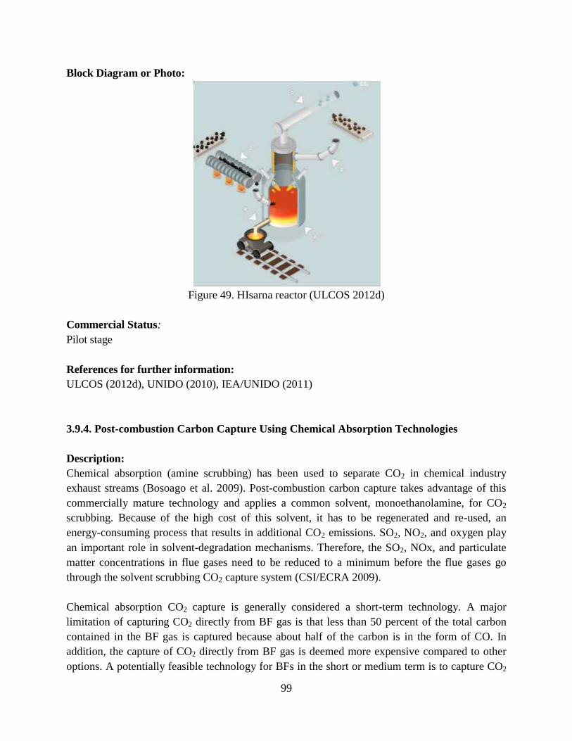
99
Block Diagram or Photo:
Figure 49. HIsarna reactor (ULCOS 2012d)
Commercial Status:
Pilot stage
References for further information:
ULCOS (2012d), UNIDO (2010), IEA/UNIDO (2011)
3.9.4. Post-combustion Carbon Capture Using Chemical Absorption Technologies
Description:
Chemical absorption (amine scrubbing) has been used to separate CO2 in chemical industry
exhaust streams (Bosoago et al. 2009). Post-combustion carbon capture takes advantage of this
commercially mature technology and applies a common solvent, monoethanolamine, for CO2
scrubbing. Because of the high cost of this solvent, it has to be regenerated and re-used, an
energy-consuming process that results in additional CO2 emissions. SO2, NO2, and oxygen play
an important role in solvent-degradation mechanisms. Therefore, the SO2, NOx, and particulate
matter concentrations in flue gases need to be reduced to a minimum before the flue gases go
through the solvent scrubbing CO2 capture system (CSI/ECRA 2009).
Chemical absorption CO2 capture is generally considered a short-term technology. A major
limitation of capturing CO2 directly from BF gas is that less than 50 percent of the total carbon
contained in the BF gas is captured because about half of the carbon is in the form of CO. In
addition, the capture of CO2 directly from BF gas is deemed more expensive compared to other
options. A potentially feasible technology for BFs in the short or medium term is to capture CO2
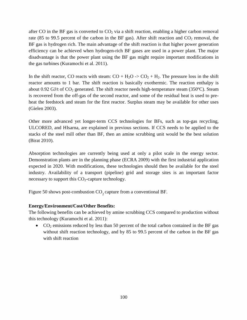
100
after CO in the BF gas is converted to CO2 via a shift reaction, enabling a higher carbon removal
rate (85 to 99.5 percent of the carbon in the BF gas). After shift reaction and CO2 removal, the
BF gas is hydrogen rich. The main advantage of the shift reaction is that higher power generation
efficiency can be achieved when hydrogen-rich BF gases are used in a power plant. The major
disadvantage is that the power plant using the BF gas might require important modifications in
the gas turbines (Kuramochi et al. 2011).
In the shift reactor, CO reacts with steam: CO + H2O -> CO2 + H2. The pressure loss in the shift
reactor amounts to 1 bar. The shift reaction is basically exothermic. The reaction enthalpy is
about 0.92 GJ/t of CO2 generated. The shift reactor needs high-temperature steam (350ºC). Steam
is recovered from the off-gas of the second reactor, and some of the residual heat is used to pre-
heat the feedstock and steam for the first reactor. Surplus steam may be available for other uses
(Gielen 2003).
Other more advanced yet longer-term CCS technologies for BFs, such as top-gas recycling,
ULCORED, and HIsarna, are explained in previous sections. If CCS needs to be applied to the
stacks of the steel mill other than BF, then an amine scrubbing unit would be the best solution
(Birat 2010).
Absorption technologies are currently being used at only a pilot scale in the energy sector.
Demonstration plants are in the planning phase (ECRA 2009) with the first industrial application
expected in 2020. With modifications, these technologies should then be available for the steel
industry. Availability of a transport (pipeline) grid and storage sites is an important factor
necessary to support this CO2-capture technology.
Figure 50 shows post-combustion CO2 capture from a conventional BF.
Energy/Environment/Cost/Other Benefits:
The following benefits can be achieved by amine scrubbing CCS compared to production without
this technology (Kuramochi et al. 2011):
CO2 emissions reduced by less than 50 percent of the total carbon contained in the BF gas
without shift reaction technology, and by 85 to 99.5 percent of the carbon in the BF gas
with shift reaction
101
Block Diagram or Photo:
Figure 50. Post-combustion CO
2 capture from a conventional BF (Gupta et al. 2003).
Commercial Status:
Development stage
References for Further Information:
Kuramochi et al. (2011), Birat (2010), Gielen (2003), Gupta et al. (2003)
3.9.5. Geological Sequestration of CO2 Using BOF or EAF Slag
Description:
The major mineral phases of BOF steelmaking slag are calcium silicate (Ca2SiO4), tricalcium
silicate (Ca3SiO5), iron calcium (Ca3Fe2O5), periclase (MgO), free calcium oxide or quicklime
(CaO) and RO (R=Fe, Mn, Mg, and Ca). In addition, chemical analysis of BOF steelmaking slag
shows that it contains around 40 percent CaO. Therefore, it could be used for long-term storage
of CO2. Typically, CO2 sequestration by steelmaking slag can be divided into direct and indirect
carbonation processes. The direct carbonation process can be further divided into dry and
aqueous processes. The dry process uses the Ca- and Mg-containing mineral particles to react
with CO2 to form carbonated minerals, permanently fixing CO2 gas. In the aqueous process,
however, water is added to form carbonic acid, and alkaline earth metals as well as other ions are
dissolved into water. This reacts with CO2 gas to precipitate carbonated minerals. In the indirect
carbonation process, solvents such as acetic acid are used to first extract alkaline earth metals and
other ions from the minerals, which are then carbonated with CO2 gas (Ma et al. 2011).
102
Although the direct carbonation process is simple, the carbonation reaction at room temperature
is slow, and the Ca-leaching ratio from the waste slag is also lower than in the indirect process.
The advantages of the indirect carbonation process include a higher Ca-extraction ratio, leaching
reaction, and carbonation reaction rates; recyclability of the leaching agent, and no secondary
pollution (Ma et al. 2011).
A project led by the University of Missouri and supported by U.S. DOE/AISI focused on
developing a process that improves the kinetics of the hydrous carbonate formation reaction to
allow steelmakers to remove CO2 directly from their furnace exhaust gas. The proposal was to
bring the CO2-containing furnace exhaust stream in contact with reclaimed steelmaking slag in a
reactor whose environment was near unit activity of water14
. This reaction would produce
carbonate products that are suitable for polymer fillers and agricultural and construction
applications. In addition to removing CO2, the process could recover some sensible heat for
process or plant services applications, reducing the plant’s overall CO2 emissions footprint (U.S.
DOE/ITP 2007b).
Ma et al. (2011) studied the leaching process, removal of impurities, and carbonation of
steelmaking plant waste slag at ambient pressure. Their results showed that ionic solutions of
calcium (Ca2+) leaching mainly occurs during the first 60 minutes of the leaching process.
Moreover, adding small amounts of Sodium hydroxide (NaOH) and triethanolamine in the
leaching solution allows effective removal of Mg2+, Al3+ and Fe3+ so that high-purity CaCO3
products can be obtained through the carbonation process (Ma et al. 2011).
Bao et al. (2010) also investigated the extraction of calcium ions from steelmaking slag using a
novel leaching medium, which involves the organic solvent tributyl phosphate, acetic acid, and
ultra-pure water.
Rawlins (2008) studied the process conditions that would increase the kinetics of carbonate
formation process under hydrous conditions, enabling direct removal of CO2 from steelmaking
off gas. This study showed that the carbonate formation rate is primarily governed by particle
size. Slag grinding will increase the reaction surface area and is itself CO2 sequestration net
positive. The grinding cost can be recouped by recovering liberated steel particles. The critical
(economic) grind size for BOF and EAF slag is 100-150 micrometers. Aqueous processing
proceeds much faster than dry processing because of separate leaching and carbonation processes
in the latter. The best results from this project show that 47 percent of the theoretical amount of
carbonation can be achieved at 24 hours in a reactor using 100-micrometer slag particles. This
amount is equal to 0.5 percent and 2.4 percent of the CO2 emitted by integrated and EAF mills,
respectively (Rawlins 2008).
14
Water activity was developed to account for the intensity with which water associateswith various non-aqueous
constituents and solids.
103
The CO2 concentration also has an effect on the Ca use of slag. At higher temperatures, a larger
Ca use appears at a lower CO2 concentration (<10 percent) or higher CO2 concentration (>75
percent). As the CO2 concentration decreases, the carbonization reaction rate increases, regardless
of the kind of slag used. With regard to the type of steel slag, EAF steel slag has better reactivity
and Ca use than BOF steel slag (Yu and Wang 2011).
Energy/Environment/Cost/Other Benefits:
The following benefits can be achieved by using steel slag to sequester carbon (U.S. DOE/ITP
2007b; Richards 2008):
The total sequestration potential for steelmaking slag is 6-11 percent of the CO2 emitted
from integrated mills and 35-45 percent emitted from scrap-based steelmakers.
Conversion of slag and exhaust gas to potentially saleable products
Capture and concentration of environmentally undesirable trace elements that are present
in slag
Recuperation of sensible heat for process or plant services application
Block Diagram or Photo:
N/A
Commercial Status:
Research stage
References for further information:
Ma et al. (2011), U.S. DOE/ITP (2007b), Rawlins (2008)
104
3.9.6. Integrating Steel Production with Mineral Sequestration
Description:
Mineral sequestration, the disposal of CO2 in the form of benign solid carbonate, is a permanent
and safe method of CO2 disposal with virtually unlimited capacity. This method of CO2 disposal
could greatly benefit from collaboration with the steel industry as the hydrometallurgical
processing of the mineral ore (peridotite rock) results in the generation of virtually pure iron
oxides. This would provide new sources of iron oxide from peridotite ores and would sequester
CO2 from the BF and other combustion operations including power plants. The steel industry is
accustomed to pre-processing iron ores prior to introducing them to the BF. If the gangue
materials could be used to chemically bind CO2, this would develop a niche market for the steel
industry, allowing it to dispose of its own CO2 (AISI 2006c).
U.S. DOE/AISI Technology Roadmap Program supported a project led by Columbia University
to develop a combination iron reduction and carbon sequestration plant that will use serpentine
ores as the source of iron and dispose of the iron-industry CO2 (as well as additional CO2 from
other sources) in the mineral tailings that remain at the end of the iron reduction process. Using
the same ore-processing steps for carbon sequestration and iron ore production increases the
value of the carbon sequestration process and reduces the cost of sequestration (AISI 2006c).
A viable mineral carbon sequestration process utilizing serpentine has never been demonstrated
because of slow reaction times with CO2 in aqueous solutions. Experiments were performed
exploring the catalytic effect that sodium chloride and ammonium chloride might have on
serpentine dissolution, which is the rate-limiting step in the overall carbonation process. It was
found that although initial dissolution rates appear to be enhanced by the presence of the salts,
long-term dissolution rates remain unaffected; therefore, these salts will not help lower the costs
of a mineral carbonation process. More research is needed to develop a viable carbon
sequestration technology using serpentine or similar minerals (Lackner et al. 2008).
Figure 51 shows an integrated mineral CO2 sequestration plant.
Energy/Environment/Cost/Other Benefits:
The following benefits could be achieved by integrating steel production with mineral
sequestration (Lackner et al. 2008):
Significant reduction of CO2 emissions
Creation of a carbon sink within the steel industry that could be sold as CO2 credits to
other industries
Production of valuable iron oxide from peridotite ores
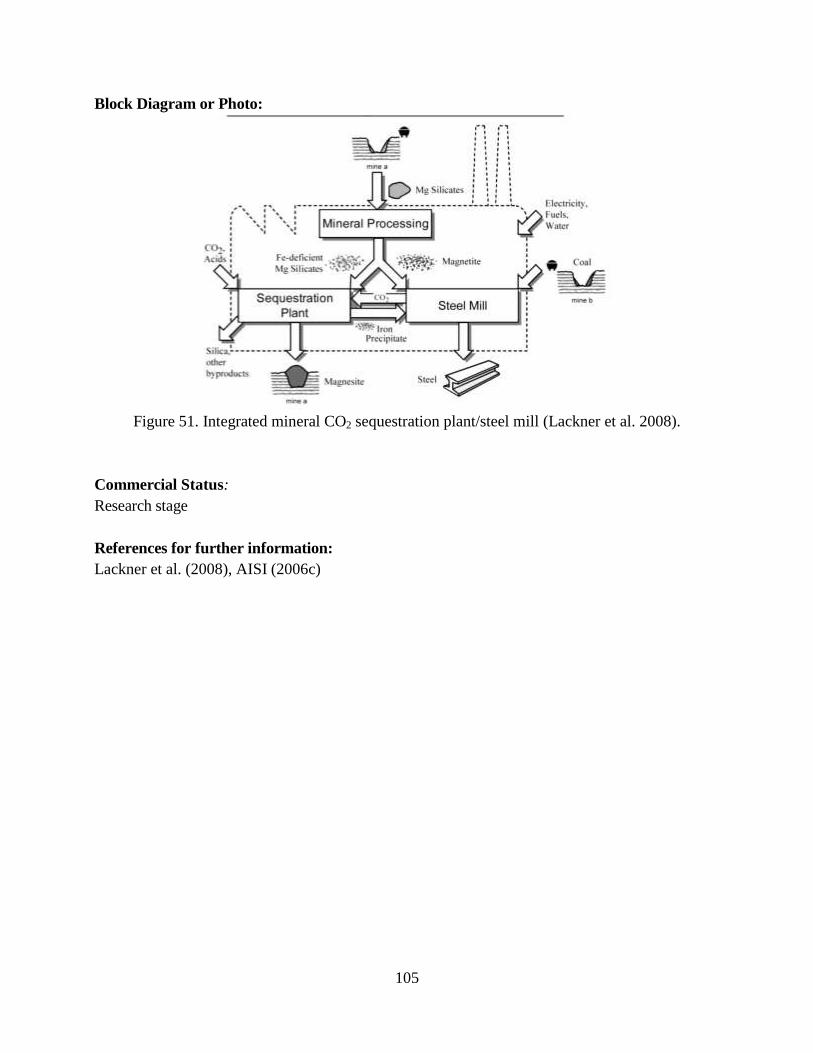
105
Block Diagram or Photo:
Figure 51. Integrated mineral CO2 sequestration plant/steel mill (Lackner et al. 2008).
Commercial Status:
Research stage
References for further information:
Lackner et al. (2008), AISI (2006c)
106
Acknowledgments
This work was supported by the China Sustainable Energy Program of the Energy Foundation
through the U.S. Department of Energy under Contract No. DE-AC02-05CH11231. The
contribution of Marlene Arens to this report was funded by Fraunhofer ISI. We are thankful (in
no particular order) to Debo Aichbhaumik and Keith Jamison of Energetics, Inc., Isaac Chan of
U.S. DOE’s Advanced Manufacturing Office, B.V. Lakshminarayana, Joe Vehec, and Peter
Pagano of American Iron and Steel Institute, and Wolfgang Eichhammer of Fraunhofer Institute
for Systems and Innovation Research for their valuable comments on the earlier version of the
report. We also would like to thank Nan Wishner for editing the report.
References
Agrawal, B.B. and A. S. Mathur, 2011. New Ironmaking Processes:Relevance to India. Available
at http://www.iim-
delhi.com/upload_events/01NewIronmakingProcessRelevanceIndia_RDCIS.pdf
American Iron and Steel Institute (AISI). 2012. Recycling of Waste Oxides in Steelmaking Furnaces. Steel
Works – The online resource for steel. Available at:
http://www.steel.org/en/Making%20Steel/Research%20and%20Development/R%20and%
20D/Recycling%20of%20Waste%20Oxides%20in%20Steelmaking%20Furnaces.aspx
American Iron and Steel Institute (AISI). 2010. Technology Roadmap Research Program for the Steel
Industry. Available at
http://www.steel.org/en/sitecore/content/Global/Document%20Types/News/2011/AISI%20Releas
es%20Final%20Report%20Of%20The%20Technology%20Roadmap%20Research%20Program%
20Describing.aspx
American Iron and Steel Institute (AISI).2006a. Technical Feasibility Study of Steelmaking by Molten
Oxide Electrolysis. (2006 TR program book, page 24-25) Available at
http://www.steel.org/Sustainability.aspx
American Iron and Steel Institute (AISI).2006b. “Suspension Hydrogen Reduction of Iron Oxide
Concentrate.” (2006 TR program book, page 20-21) Available at
http://www.steel.org/Sustainability.aspx
American Iron and Steel Institute (AISI). 2006c. “Integrating Steel Production with Mineral
Sequestration.” (2006 TR program book, page 26-27) Available at
http://www.steel.org/Sustainability.aspx
American Iron and Steel Institute (AISI).2002. “Evaluation of Sustainable Steelmaking Using Biomass
and Waste Oxides.” Brochure. (2002 TR program book, page 35-36) Available at
http://steeltrp.com/PDFs/9902.pdf
Asia Pacific Partnership on Clean Development and Climate (APP). 2010. The State–of-the-Art Clean
Technologies (SOACT) for Steelmaking Handbook. (2nd Edition). Available at
http://asiapacificpartnership.org/english/soact2nd.aspx
Asmet. 2011. “New Pig Iron Process ‘Tecnored Technology’ Tested by Vale.” September 27. Available at
http://www.asmet.com/news/new-pig-iron-process-tecnored-technology-tested-by-vale
107
Arvedi, G., F. Mazzolari, A. Bianchi, G. Holleis, J. Siegl, and A. Angerbauer. 8. “The Arvedi endless
strip production line (ESP) from liquid steel to hot-rolled coil in seven minutes.” La Revue de
Métallurgie-CIT, July/August, pp. 398-407.
Bao, W., H. Li,Y. Zhang. 2010. “Selective Leaching of Steelmaking Slag for Indirect CO2 Mineral
Sequestration.” Ind. Eng. Chem. Res. 49: 2055–2063.
Barati, M., S. Esfahani, T.A. Utigard. 2011. “Energy recovery from high temperature slags.” Energy.
Volume 36, Issue 9, September, pp, 5440–5449.
Bellevrat, E., P. Menanteau. 2008. “Introducing carbon constraint in the steel sector: ULCOS scenarios
and economic modeling.” Proceedings of the 4th Ulcos seminar, 1-2 October. Available at
www.ulcos.org/en/docs/.../Ref01%20-%20SP9_Bellevrat_Essen.pdf
Bergman, L., M. Larsson. 2008. “HSC Simulations of coal based DR in ULCORED.” Proceedings of the
4th Ulcos seminar, 1-2 October.
BFI (VDEh-Betriebsforschungsinstitut/Institute for Applied Research). 2012. Steel temperature
measurement in electric steel plants (EAF/LF). Available at
http://www.bfi.de/en/fields_of_activity/process_analysis_techniques/steel_temperature_electric_st
eelmaking.htm
BFI. 2009/2010. Tätigkeitsbericht/Activity Report 2009/2010. Von der Idee zur betrieblichen Lösung/
From the idea to the industrial solution. Düsseldorf, Germany. Available at
http://www.bfi.de/de/betriebsforschungsinstitut/BFI-Taetigkeitsbericht-2009-2010.pdf
Bisio, G. 1997. “Energy recovery from molten slag and exploitation of the recovered energy.” Energy.
Volume 22, Issue 5, May, pp. 501–509.
BCS, Incorporated. 2005. “Advanced Melting Technologies: Energy Saving Concepts and Opportunities
for the Metal Casting Industry.” Available at
http://www.eere.energy.gov/manufacturing/industries_technologies/metalcasting/pdfs/advancedm
eltingtechnologies.pdf
Birat, J.P., 2010. “Steel sectoral report - Contribution to the UNIDO roadmap on CCS1 - fifth draft.”
Available at www.unido.org/fileadmin/user.../Stee_sectoral_%20report.pdf
Birat, J.P., J. Borlée, B. Korthas, J. van der Stel, K. Meijer, C. Günther, M. Halin, T. Bürgler, H.
Lavelaine, C. Treadgold, I. Millar, D. Sert, T. Torp, F. Patisson, B. Paya, E. Burstrom. 2008.
ULCOS program: a progress report in the Spring of 2008. 3rd International Conference on
Process Development in Iron and Steelmaking. Available at www.ulcos.org/en/docs/Ref09%20-
%20ULCOS_Scanmet%20III.pdf
Birat J.P., F. Hanrot, G. Danloy. 2003. “CO2 Mitigation Technologies in the Steel Industry: a
Benchmarking Study Based on Process Calculations.” Stahl und Eisen, 123 (9), 2003: 69-72.
Birat, J.P., C. Grisvard, J.C. Hubert, B. Gros, J.J. Almon. 2001. “Charging tires in the EAF as a substitute
to carbon.” Journées Sidérurgiques Internationales, Paris, France, 12-13 December.
Borlée, J. 2007. “Low CO2 steels - ULCOS project (Ultra Low CO2 Steelmaking).” Presented in IEA
Deployment workshop, October 9.
Bosoago, A., M. Ondrej, J.E. Oakey. 2009. “CO2 Capture Technologies for Cement Industry”. Energy
Procedia, Vol. 1:133-140.
Brown, C.J., D.R. Olsen. 2006. “Regeneration of Hydrochloric Acid Pickle Liquors by Crystallization.”
Third International Symposium in Iron Control in Hydrometallurgy, Montreal, Canada, October 1-
4.
108
Castrip. 2012. The Castrip® process. Available at http://www.castrip.com/Process/process.html
Cement Sustainability Initiative (CSI) and European Cement Research Academy (ECRA). 2009.
Development of State-of-the-Art Techniques in Cement Manufacturing: Trying to Look Ahead
(CSI/ECRA-Technology Papers). Available at
http://www.wbcsdcement.org/pdf/technology/Technology%20papers.pdf
Chu M., X., Yang, F. Shen, J. Yagi, H. Nogami. 2006. “Numerical Simulation of Innovative Operation of
Blast Furnace Based on Multi-Fluid Model.” Journal of Iron and Steel Research, International.
2006, 13(6): 8-15.
Clauzade, C. 2006. End-of-life tires in electric arc furnaces: an industrial success story. Available at
http://www.coprocem.org/documents/Tyres%20in%20Electric%20Arc%20furnaces.pdf
Cotchen, J.K. and M. J. Stercho., 2002. “Continuous Horizontal Sidewall (CHS) scrap charging.”
Available at http://cat.inist.fr/?aModele=afficheN&cpsidt=14418054
Cramb, A.W. 2004. “Strip Casting of Steels: Current Developments.” Encyclopedia of Materials: Science
and Technology. New York: Elsevier Ltd, pp. 1-4.
http://www1.elsevier.com/emsat/pdf/300102.pdf
Danieli Corus. No date (n.d.). “The Tecnored Process. A New Route For Producing Low Cost Liquid Iron.”
Available at
ftp://ftp.cefetes.br/Cursos/EngenhariaMetalurgica/Marcelolucas/Disciplinas/Reducao/Material%2
0Tecnored/Brochure.pdf
Danieli and Tenova. 2011. “HYL Process Description.” Available at
http://www.energiron.com/default.htm
Das, B., S. Prakash, P. S. R. Reddy, S. K. Biswal, B. K. Mohapatra, V. N. Misra. 2002. “Effective
Utilization of Blast Furnace Flue Dust of Integrated Steel Plants.” The European Journal of
Mineral Processing and Environmental Protection. Vol. 2, No. 2: 61-68.
De Beer, J., K. Blok, E. Worrell. 1998a. “Future Technologies for Energy-Efficient Iron and Steelmaking.”
Annual Review of Energy and the Environment. Vol. 23: 123-205;
De Beer, J., K. Blok, E. Worrell. 1998b. “Long-term energy-efficiency improvements in the paper and
board industry.” Energy. 23 (1): 21-42.
De Saro R., A. Weisberg, J. Craparo. 2005a. “In Situ, Real Time Measurement of Aluminum, Steel, and
Glass Melt Chemistries Using Laser Induced Breakdown Spectroscopy.” Energy Research
Company. Conference Paper at the ACEEE Summer Study on Energy Efficiency in Industry.
Available at
http://www.eceee.org/conference_proceedings/ACEEE_industry/2005/Panel_1/p1_3/paper
De Saro R., A. Weisberg, J. Craparo. 2005b. In Situ, Real Time Measurement of Melt Constituents in the
Aluminum, Glass, and Steel Industries. Final Report. Energy Research Co. Available at
http://www.osti.gov/bridge/servlets/purl/902660-lOsPpB/902660.pdf
D ez, M. A., R. Alvarez, C. Barriocanal. 2002. “Coal for metallurgical coke production: predictions of
coke quality and future requirements for cokemaking.” International Journal of Coal Geology.
Volume 50, Issues 1–4, May 2002, pp. 389–412.
Doronin, I. E., A. G. Svyazhin. 2011. “Commercial methods of recycling dust from
steelmaking.”Metallurgist, Volume 54, Numbers 9-10 (2011), 673-681, DOI: 10.1007/s11015-
011-9356-z
109
European Integrated Pollution Prevention and Control Bureau (EIPPCB). 2010. Best Available Techniques
(BAT) Reference Document for Iron and Steel Production Industrial Emissions Directive
2010/75/EU. Available at http://eippcb.jrc.es/reference/BREF/IS_Adopted_03_2012.pdf
European Cement Research Academy GmbH (ECRA). 2009. ECRA CCS Project - Report about Phase II.
Available at http://www.cement.org/bookstore/profile.asp?id=16950
EIPPCB. 2008. Best Available Techniques- Reference Document on the Production of Iron and Steel,
(draft version February 2008), European Commission, Directorate-General JRC, Institute for
Prospective Technology Studies, Seville, Spain.
EIPPCB. 2001. Reference Document on Best Available Techniques for the Production of Iron and Steel.
European Commission.
Energetics, Inc. 2004. Steel Industry- Energy Bandwidth Study. Available at
www1.eere.energy.gov/industry/steel/pdfs/steelbandwidthstudy.pdf
Farla, J.C.M., E. Worrell, L. Hein, and K. Blok. 1998. Actual Implementation of Energy Conservation
Measures in the Manufacturing Industry 1980-1994. The Netherlands: Utrecht University Dept. of
Science, Technology & Society.
Fruehan, R. J. 2004a. Future Steelmaking Processes: Final Report. United States Department of Energy
(U.S. DOE). Available at www.osti.gov/bridge/servlets/purl/840930
Fruehan, R. J. 2004b. Sustainable Steelmaking Using Biomass and Waste Oxides: Final Technical Report.
U.S. DOE, Office of Industrial Technologies (OIT). Available at
http://www1.eere.energy.gov/manufacturing/industries_technologies/steel/pdfs/report_trp_9902.p
df
Fruehan R.J. and R.J. Matway. 2004. “Optimization of Post Combustion In Steelmaking.” Available at
www1.eere.energy.gov/manufacturing/.../post_combustion.pdf
Gielen, D. 2003. “CO2 removal in the iron and steel industry.” Energy Conversion and Management 44:
1027–1037.
Grandmaison, E.W., D Poirier.J., E. Boyd. 2003. “Development Of An Oxygen-enriched Furnace System
For Reduced CO2 and NOx Emissions For The Steel Industry.” Prepared for U.S. Department of
Energy. Available at: http://steeltrp.com/finalreports/finalreports/9806NonPropFinalReport.pdf
Grill, W. 2009. “The SIMETALCIS Corex / Finex Process.” Convention on clean, green and sustainable
technologies in iron and steel making.15 – 17 July. Bhubaneswar, India.
Gupta, M., I. Coyle, K. Thambimuthu. 2003. “CO2 Capture Technologies and Opportunities in Canada -
Strawman Document for CO2 capture and Storage (CC&S) Technology Roadmap.” 1st Canadian
CC&S Technology Roadmap Workshop, 18-19 September, Calgary, Alberta, Canada.
Hacala, A., U. Michon. 2009. “Innovative industrial plasma torch for converting biomass into high purity
syngas.” ISPC19 - 2009, Bochum, Germany. Available at www.ispc-
conference.org/ispcproc/papers/39.pdf
Halder, S. 2011. “An Experimental Perspective on Praxair’s Hot Oxygen Technology to Enhance
Pulverized Solid Fuel Combustion for Ironmaking Blast Furnaces.” Praxair Inc. Technical Paper.
Available at
http://www.praxair.com/praxair.nsf/AllContent/31B770CF22B3FBBF8525799F0075226F?Open
Document
110
Hasanbeigi, A., W. Morrow, J. Sathaye, E. Masanet, T. Xu. 2012. Assessment of Energy Efficiency
Improvement and CO2 Emission Reduction Potentials in the Iron and steel Industry in China.
Report. Berkeley, CA: Lawrence Berkeley National Laboratory Report LBNL- LBNL-5535E.
Indian Centre for Plastic in the Environment (ICPE). 2006. Management of plastics, polymer wastes and
Bio-polymers and impact of plastic on the eco-system.
Institute of Materials Processing (IMP)/Michigan Technological University (MTU). 2006. Verification Of
Steelmaking Slag Iron Content. Final technical progress report. Available at
www1.eere.energy.gov/industry/steel/pdfs/report_trp_slag.pdf
INTEG process group, Inc. 2004. “Hot Strip Mill Model.” Available at
www.integpg.com/hsmm/files/HSMM_Overview_Rel_2_0.pdf
International Energy Agency (IEA). 2010. “The Energy Technology Systems Analysis Program (ETSAP)-
Technology Brief: Iron and Steel.” Available at http://www.iea-etsap.org/web/E-
TechDS/Technology.asp
IEA. 2007. Tracking Industrial Energy Efficiency and CO2 Emissions. Available at:
http://www.iea.org/w/bookshop/add.aspx?id=298
IEA/ United Nations Industrial Development Organization (UNIDO). 2011. “Technology Roadmaps:
Carbon Capture and Storage in Industrial Applications.” Available at
www.iea.org/papers/roadmaps/ccs_industry.pdf
Japan Iron and Steel Federation (JISF). 2012a. Technologies to support COURSE 50. Available at
http://www.jisf.or.jp/course50/tecnology03/index_en.html
JISF. 2012b. COURSE 50 - Technologies to reduce CO2 emissions. Available at
http://www.jisf.or.jp/course50/tecnology01/index_en.html
JFE Engineering. 2004. “Ecologically-Friendly and Economical Arc Furnace ‘ECOARC.’” JFE Technical
report. No. 3, July. Available at www.jfe-steel.co.jp/en/research/report/003/pdf/003-16.pdf
Joulazadeh, M. H. 2008. “Using Scrap Tires in EAFs as a Substitute for Carbon.” International Journal of
ISSI, Vol.5, No. 1, pp. 36-40.
JP Steel Plantech Co. 2012. “ECOARC.” Available at
http://www.steelplantech.co.jp/english/products/steelmaking/eaf/ecoarc/
JP Steel Plantech Co. 2005. “Waste Plastics Injection System for BF.” Available at http://www.jase-
w.eccj.or.jp/technologies/pdf/iron_steel/S-02.pdf Júniora, J.H.N., M.A. Contruccib, J.C D’Abreuc.
2005. “Tecnored Process - High Potential in Using Different Kinds of Solid Fuels.” Materials
Research, Vol. 8, No. 4, pp. 447-451. Available at http://www.scielo.br/scielo.php?pid=S1516-
14392005000400016&script=sci_arttext
Kazuya, Y., T. Hirokazu, T. Tatsuhito. 2006. “New Applications of Iron and Steelmaking Slag
Contributing to a Recycling-oriented Society.” JFE Technical report. No. 8. October..
Kempgen, J., J. Schlüter, U. Falkenreck, W. Weischedel. 2008. “New scrap-based steelmaking process
predominantly using primary energy.” Millenium Steel 2008. Available at www.millennium-
steel.com/articles/pdf/2008/pp96-98%20MS08.pdf
Knop, K., M. Hallin, E. Burström. 2008. “ULCORED SP 12- Concept for minimized CO2 emission.”
Proceedings of the 4th Ulcos seminar, 1-2 October.
König, U., J. Hållstedt, J. Noreland, K. Vallo, L. Gobbo, T. Füllmann, K. Macchiarola, J. Nieminen. 2010.
“Using X-ray diffraction.” Nordic Steel and Mining Review.
111
Kono, Y., Y. Iguchi, M. Shimizu. 2000. “The Basis and Application for Carbon Reduction of Iron Oxide”,
ISIJ, Tokyo, Japan, 31-36.
Kuramochi, T., A. Ramírez, W. Turkenburg, A. Faaij. 2011. “Techno-economic assessment and
comparison of CO2 capture technologies for industrial processes: preliminary results for the iron
and steel sector.” Energy Procedia 4: 1981–1988.
Lackner, K.S., P. F. Duby, T. Yegulalp, S. Krevor, C. Graves. 2008. Integrating Steel Production with
Mineral Carbon Sequestration. Available at
steeltrp.com/finalreports/finalreports/9957NonPropFinal.pdf
Leimalm, U., M. Lundgren, L. Sundqvist Ökvist, B. Bjorkman. 2010. “Off-gas Dust in an Experimental
Blast Furnace Part 1: Characterization of Flue Dust, Sludge and Shaft Fines.” ISIJ International,
Vol. 50, No. 11, pp. 1560–1569.
Lockwood G2000. Ironmaking Process Alternatives Screening Study - Volume I: Summary Report.
Available at www1.eere.energy.gov/manufacturing/.../ironmaking_process.pdf
Lu, W.K., 2008. “The Search for a New Ironmaking Process Towards Sustainable Development.” GCEP
“Industry” Workshop, Stanford University, April 15‐16. Available at
gcep.stanford.edu/pdfs/.../Lu_New_Sustainable_Ironmaking.pdf
Luiten, E. and K. Blok. 2003. “Stimulating R&D of Industrial Energy-Efficient Technology; the Effect of
Government Invervention on the Development of Strip Casting Technology.” Energy Policy 31,
pp. 1339-1356.
Ma, G.J, H. Tangb, Y. Jin. 2011. “Mineral Sequestration of CO2 Using Basic Oxygen Furnace (BOF)
Steelmaking Slag.” Advanced Materials Research, Vols. 194-196, pp 2140-2144.
Maiolo, J., M. Boutazakhti, C.W. Li, C. Williams. 2007. “Developments towards an Intelligent Electric
Arc Furnace at CMC Texas using Goodfellow EFSOP® Technology.” AISTech, Indianapolis,IN,
May 7-10.
Matsumura, T., Y. Takenaka, M. Shimizu. 1999. “Effect of the carbon content on the reduction and
melting behavior of carbon composite iron ore pellet.” Tetsu-to-Hagane 85: 652-657.
Meng, F., Y. Iguchi, I. Kojima. 2001. “Reduction, carburization and melting behavior of iron ore pellets
containing coal char or graphite on heating.” Tetsu-to-Hagane 87: 585-592.
Mesabi Nugget Delaware, LLC and Mining Resources, LLC.2011. “The Mesabi Nugget Story.” Available
at http://www.mesabinuggetmn.com/
MIDREX Technologies, Inc. 2012. “Direct Reduction- Shaft Furnace and Rotary Hearth Furnace (RHF).”
Available at http://www.midrex.com/handler.cfm/cat_id/17/section/technology
MIDREX Technologies, Inc. 2011. “MXCOL®: A breakthrough in coal-based direct reduction.”
Available at http://www.midrex.com/uploads/documents/MXCOL-English%20article%20US.pdf
Nashan, G. 2007. “Strategies to increase the technical and economic efficiency of the blast furnace
ironmaking process by using new advanced cokemaking technologies.” Available at www.coke-
oven-managers.org/PDFs/2007/2007%20-%20Nashan.pdf
Nippon Steel Corp. No date (n.d.). Dust and Sludge Recycling with the Rotary Hearth Furnace. Available
at www.nsc.co.jp/en/tech/report/pdf/n9215.pdf
Oda, H., T. Ibarkai, Y. Abe. 2006. Dust Recycling System by the Rotary Hearth Furnace. Nippon Steel
Technical Report No. 94 July 2006. Available at www.nsc.co.jp/en/tech/report/pdf/n9424.pdf
112
Ooi, T.C., D. Thompson, D. R. Anderson, R. Fisher, T. Fray, M. Zandi. 2011. “The effect of charcoal
combustion on iron-ore sintering performance and emission of persistent organic pollutants.”
Combustion and Flame 158: 979–987.
Outotec, Inc. 2012. “Circored® and Circofer®: Fine Ore Reduction in the Circulating Fluidized Bed.”
Available at http://www.outotec.com/pages/Page.aspx?id=7250&epslanguage=EN
Outotec, Inc. 2007. “Fluidization technology.” Available at www.outotec.com/36280.epibrw
Peaslee K.D., V.L. Richards, D. G.C. Robertson, J. D. Smith. 2006. Development of a Process to
Continuously Melt, Refine and Cast High Qulity Steel. Final Technical Report. Project funded by
the U. S. Department of Energy under Award No. DE-FC36-03ID14279. Available at
http://www1.eere.energy.gov/manufacturing/industries_technologies/steel/pdfs/finaltechreport.pdf
Poirier D., E.W. Grandmaison, A.D. Lawrence, M.D. Matovic, E. Boyd. 3. “Oxygen-enriched
Combustion Studies with the Low NOX CGRI Burner.” Combustion Canada 3 Conference –
Vancouver, BC Sept. 22-24, 2003. Available at:
http://chemeng.queensu.ca/people/faculty/grandmaison/publications/Poirier%20et%20al%20-
%20Combustion%20Canada%202003.pdf
Rawlins, C.H. 2008. Geological Sequestration of Carbon Dioxide by Hydrous Carbonate Formation in
Steelmaking Slag. PhD dissertation. Missouri University of Science and Technology. Available at
scholarsmine.mst.edu/thesis/pdf/Rawlins_09007dcc804d4f95.pdf
Rebello, W.J., K. H. Kohnken, H. R. Phipps Jr. 1980. “Estimation of Fuel Savings by Recuperation of
Furnace Exhausts to Preheat Combustion Air.” Proceedings from the Second Industrial Energy
Technology Conference, Houston TX, April 13-16,.
Richards, V.L. 2008. Geological Sequestration of CO2 by Hydrous Carbonate Formation With Reclaimed
Slag. AISI/DOE Technology Roadmap Program for the Steel Industry. Available at
http://steeltrp.com/finalreports/finalreports/9955NonPropFinalReport.pdf
Riley, M.F. 2002. Hot Oxygen Injection Into The Blast Furnace. Final Report. AISI/DOE Technology
Roadmap Program. Available at
steeltrp.com/finalreports/finalreports/9718NonPropFinalReport.pdf
Rohde W., J. Strunk. 1998. “Comparison of coking behavior of coal blends in the single chamber system
and in conventional high capacity coke ovens.” Fuel and Energy Abstracts, Volume 39, Number 1,
January, pp. 10-10(1)
Shimizu, T., D. Haga, G. Mikami,T. Takahashi, K. Horinouchi. 2010. “Heat recovery from melted blast
furnace slag using fluidized bed.” 61st IEA-FBC Meeting. October 28-29, Salerno, Italy.
Available at http://www.processeng.biz/iea-fbc.org/index.php?site=event/61th+IEA-
FBC+MeetingOctober+28-29%2C+2010&u=p
Siemens VAI. 2007. “Competence in Ironmaking.” Available at
www.industry.siemens.com/.../Competence-in-Ironmaking-en.pdf
Sahajwalla,V., M. Zaharia, M. Rahman, R. Khanna, N. Saha-Chaudhury, P. O'Kane, J. Dicker, C.
Skidmore, D. Knights. 2011. “Recycling Rubber Tyres and Waste Plastics in EAF Steelmaking.”
steel research international, Volume 82, Issue 5, pp. 566–572, May,
Sahajwalla,V., M. Zaharia, S. Kongkarat, R. Khanna, N. Saha-Chaudhury, P. O'Kane. 2010. “Recycling
Plastics as a Resource for Electric Arc Furnace (EAF) Steelmaking: Combustion and Structural
Transformations of Metallurgical Coke and Plastic Blends.” Energy Fuels, 2010, 24 (1): 379–391.
SAIL, 2012. Press Release: SAIL, Kobe Steel seal pact to bring environment-friendly steel making to
India. Available at http://www.sail.co.in/showpressrelease.php?id=305
113
Schliephake, H., C. Born, R. Granderath, F. Memoli, J. Simmons. 2011. Heat Recovery for the EAF
of Georgsmarienhütte, Germany. Tenova technical article, Iron & Steel Technology 02/05/2011.
Available at
http://www.tenovagroup.com/technical_articles.php?page=1&id_product_line=1&data=
Shulkosky, R.A., D. L. Rosburg, J. D. Chapman. 2005. “Validation of the Hot Strip Mill Model.”
Available at steeltrp.com/PDFs/0040.pdf
Siemens, 2011. Press release: Siemense receives third FINEX order from POSCO. Available at
http://www.siemens.com/press/en/pressrelease/?press=/en/pressrelease/2011/industry_solutions/iis
201109998.htm
Solena Group. No date (n.d.). “The Commercial Viability of Plasma Technology- A White Paper.”
Available at sgibiopower.com/files/plasma.pdf
Sosinsky, D., P. Campbell., R. Mahapatra, W. Blejde, and F. Fischer. 2008. “The CASTRIP® process –
recent developments at Nucor Steel’s commercial strip casting plant.” Metallurgist 52, pp. 691 -
699.
Stebbing, L. 2005. “Using Scrap Tires as an Alternative Fuel Source.” Available at:
http://www.acceleratedtech.com/tire_info.htm
Stelco. 1993. “Present and Future Use of Energy in the Canadian Steel Industry.” Ottawa, Canada:
CANMET.
Tenova Key Technologies Industriebau GmbH. 2009. “Recovery of acid and oxide by-
products from spent pickling liquor.” Metallurgical Plant and Technology 1: 52–53.
Tenova HYL. 2011. “Press Release May 2011: JSPL Selects Energiron for Four New DR Plants”.
Available at http://www.tenovagroup.com/pdf/press/60-Jindal%20press%20release.pdf
Tenova HYL. 2008. “Improved Technologies for Cost Effective Steelmaking.” Metal Bulletin/MJunction.
Indian Steel 2008 Conference. Mumbai, India. Feb.
Thekdi, A. 2010. Development of Next Generation Heating System For Scale Free Steel Reheating-Final
Technical report. Available at www1.eere.energy.gov/industry/steel/pdfs/scale_free_reheat.pdf
Travernier, H., C. Grisvard , H.P. Jung, P. Drissen. 2004. Foaming of the slag and recycling of stainless steel
dusts by injection into the electric arc furnace for stainless steels. Final Report. European
Commission. Research Directorate-General, European Commission. Directorate-General Science,
Research and Development. Abstract available at
http://cat.inist.fr/?aModele=afficheN&cpsidt=15438513
Ueki, Y., H. Maeda, H. Nakagawa, M. Shimizu. 2001. “Effect of atmospheric gas composition on
reduction of high density carbon composite pellet.” CAMP-ISIJ,14, 82Ultra - low CO2
Steelmaking ( ULCOS ), 2012a. “ULCOWIN: Alkaline Electrolysis.” Available at
http://www.ulcos.org/en/research/electrolysis.php
ULCOS. 2012a. “Alkaline Electrolysis.” Available at http://www.ulcos.org/en/research/electrolysis.php
ULCOS. 2012b. “Top Gas Recycling.” Available at http://www.ulcos.org/en/research/blast_furnace.php
ULCOS. 2012c. “ULCORED.” Available at
http://www.ulcos.org/en/research/advanced_direct_reduction.php
ULCOS. 2012d. “HIsarna smelter technology.” Available at http://www.ulcos.org/en/research/isarna.php#
United Nations Industrial Development Organization (UNIDO). 2010. Carbon Capture and Storage in
Industrial Applications: Technology Synthesis Report. Available at
www.unido.org/.../CCS_%20industry_%20synthesis_final.pdf
114
University of New South Wales (UNSW). 2012. Solid State & Elemental Analysis Unit. Available at
http://www.sseau.unsw.edu.au/xrd/xrdlab.htm
U.S. Department of Energy (DOE). 2001. Recycling of Waste Oxides in Steelmaking. Notice of Energy
RD&D Project. Available at:
http://steeltrp.com/finalreports/finalreports/9760NonPropFinalReport.pdf
U.S. Department of Energy (U.S. DOE), Advanced Manufacturing Office (AMO). 2012. “Industries and
Technologies.” Available at
http://www1.eere.energy.gov/industry/industries_technologies/index.html
U.S. DOE/ Industrial Technologies Program (ITP). 2011a. Paired Straight Hearth Furnace. Available at
www1.eere.energy.gov/.../steel/.../paired_straight_hearth_furnace.pdf
U.S. DOE/ ITP. 2011b. Thermochemical Recuperation for High Temperature Furnaces. Available at
www1.eere.energy.gov/.../steel/.../thermochemical_recuperation.pdf
U.S. DOE/ Industrial Technologies Program (ITP). 2010a. IMPACTS: Industrial Technologies Program:
Summary of Program Results for CY 2009. Available at
https://www1.eere.energy.gov/manufacturing/
U.S. DOE/ ITP. 2010b. Energy Technology Solutions: Public-Private Partnerships Transforming Industry.
Available at www1.eere.energy.gov/industry/pdfs/itp_successes.pdf
U.S. DOE/ ITP. 2007a. Next Generation Heating System for Scale-Free Steel Reheating. Available at
http://www1.eere.energy.gov/manufacturing/industries_technologies/steel.html
U.S. DOE/ ITP. 2007b. Geological Sequestration of CO2 by Hydrogen. Carbonate Formation with
Reclaimed Slag. Available at
http://www1.eere.energy.gov/manufacturing/resources/steel/pdfs/geo_co2seq.pdf
U.S. DOE/ ITP. 2005. Process to Continuously Melt, Refine, and Cast High Quality Steel. Continuous
transfer process could replace current ladle operations. Energy Efficiency and Renewable Energy
Available at
http://www1.eere.energy.gov/manufacturing/industries_technologies/steel/pdfs/dev_of_process.pd
f
U.S. DOE/ITP. 2005b. NOx Emission Reduction by Oscillating Combustion. Available at:
http://www1.eere.energy.gov/manufacturing/industries_technologies/steel/pdfs/nox_reduction2.pdf
U.S. DOE/ ITP. 2004. In-Situ, Real-Time Measurement of Melt Constituents. Laser-Induced Breakdown
Spectroscopy (LIBS) Provides Real-Time Analysis of Elemental Constituents to Improve Product
Quality.
http://www1.eere.energy.gov/manufacturing/industries_technologies/aluminum/pdfs/real_time_m
easurement.pdf
U.S. DOE/Office of Industrial Technologies (OIT). 2002. Recycling and Reuse of Basic Oxygen
Furnace (BOF)/ Basic Oxygen Process (BOP) Steelmaking Slag. Available at
www1.eere.energy.gov/manufacturing/industries.../recycling_bof.pdf
U.S. DOE/ OIT. 2001a. In-Situ, Real-Time Measurement of Melt Constituents. Steel Project Fact Sheet.
Available at
http://www1.eere.energy.gov/manufacturing/industries_technologies/aluminum/pdfs/real_time_m
easurement.pdf
U.S. DOE/OIT. 2001b. NOx Emission Reduction By Oscillating Combustion. Available at:
http://eelndom1.ee.doe.gov/OIT/oitpdf.nsf/Files/oscillsteel.pdf/$file/oscillsteel.pdf
115
U.S. DOE/OIT. 2001c. Recycling of Waste Oxides in Steelmaking Furnaces. Available at:
http://www1.eere.energy.gov/manufacturing/industries_technologies/mining/pdfs/waste_oxides.pdf
U.S. DOE/ OIT. 2000. Energy Saving Regeneration of Hydrochloric Acid Pickling Liquor. Available at
www.nrel.gov/docs/fy00osti/28232.pdf
U.S. DOE/OIT. 1999. Development of an O2-Enriched Furnace System For Reduced CO2 and NO2
Emissions. Washington, D.C. 20585. Available at:
http://www1.eere.energy.gov/manufacturing/industries_technologies/steel/pdfs/o2_furnace.pdf
U.S. Environmental Protection Agency (U.S. EPA). 2010. Available and Emerging Technologies for
Reducing. Greenhouse Gas Emissions from the Iron and Steel Industry. Available at
www.epa.gov/nsr/ghgdocs/ironsteel.pdf
U.S. Geological Survey (USGS). 2012. Mineral Commodity Summaries- Iron and Steel. Available at
http://minerals.usgs.gov/minerals/pubs/commodity/iron_&_steel/mcs-2012-feste.pdf
van Boggelen, J. 2012. “HIsarna, a Low CO2 Ironmaking Process.” Presentation at Cleveland Institution
of Engineers, Middlesbrough, UK. Available at
http://www.cieng.org/events/lectures%202011%20-%202012%20session/2012-01-
10%20hisarna/2012%2001%2010%20for%20publication%20v3.pdf
Wagner, J.C. 2004. NOx Emission Reduction By Oscillating Combustion. Final Report. U.S. Department of
Energy Contract No. DE-FC36-96EE41260. Available at:
http://www.osti.gov/bridge/servlets/purl/828180-lWZ8O8/native/828180.pdf
World Steel Association (worldsteel). 2011. Steel Statistical Yearbook 2011.
http://www.worldsteel.org/statistics/statistics-archive/yearbook-archive.html
worldsteel. No date (n.d.). CO2 Emissions Data Collection – User Guide, Version 6.
http://www.worldsteel.org/climatechange/files/2/2/Data%20collection%20user%20guide.pdf
Worrell, E., P. Blinde, M. Neelis, E. Blomen, E. Masanet. 2010. Energy Efficiency Improvement and Cost
Saving Opportunities for the U.S. Iron and Steel Industry: An ENERGY STAR Guide for Energy
and Plant Managers. Available at www.energystar.gov/ia/business/industry/Iron_Steel_Guide.pdf
Worrell, E., J.A. Laitner, M. Ruth,M., and H. Finman. 3, “Productivity Benefits of Industrial Energy
Efficiency Measures.” Energy 11, 28:1081-1098.
Yagi, J.I., H. Nogami, M. Chu. 2003. “Numerical analysis on blast furnace performance by multi-
dimensional transient simulator based on multi-fluid theory.” Third International Conference on
CFD in the Minerals and Process Industries, CSIRO, Melbourne, Australia, 10-12 December.
Available at www.cfd.com.au/cfd_conf03/papers/037Yag.pdf
Yu, J., K. Wang. 2011. “Study on Characteristics of Steel Slag for CO2 Capture.” Energy Fuels 2011, 25:
5483–5492.
Zaharia, M., V. Sahajwalla, B. ChulKim, R. Khanna, N. Saha-Chaudhury, P.
O’Kane, J. Dicker, C. Skidmore, D. Knights. 2009. “Recycling of Rubber Tires in Electric Arc
Furnace Steelmaking: Simultaneous Combustion of Metallurgical Coke and Rubber Tires Blends.”
Energy & Fuels 2009, 23,:2467–2474.Zandi, M., M. Martinez-Pacheco, T. A.T. Fray. 2010.
Biomass for iron ore sintering. Minerals Engineering. Volume 23, Issue 14, November 2010,
Pages 1139–1145
Zhang, X., R. Takahashi, J. Yagi., 1995. “Reaction rates of oxidized iron-scrap briquette with pulverized
coke in nitrogen atmosphere.” Tetsu-to-Hagane 81: 1043-1048.

116
Zuliani, D.J., V. Scipolo, C. Born. 2010. “Opportunities for increasing productivity, lowering operating
costs and reducing greenhouse gas emissions in EAF and BOF steelmaking.” Millennium Steel
India 2010. Available at www.millennium-steel.com/articles/pdf/.../pp35-42%20MSI10.pdf


![Glycogen and Extracellular Glucose Estimation from ...[Abstract] Cyanobacteria, which have the extraordinary ability to grow using sunlight and carbon dioxide, are emerging as a green](https://img.dokumen.tips/doc/110x75/5e390a444804df2a9252b933/glycogen-and-extracellular-glucose-estimation-from-abstract-cyanobacteria.jpg)