Embed Size (px)
Citation preview
DOCUMENT # 010-0052 ECO # REVISION H
TEMPEST T-128 ROTATIONAL SIREN
INSTALLATION, OPERATION, MAINTENANCE
AND PARTS MANUAL
8600 West Bradley Road Milwaukee, WI 53224-2816
(414) 358-8000
2
TABLE OF CONTENTS
DESCRIPTION PAGE GENERAL INFORMATION 3 Siren Unit 3 Activation 3 Siren Installation 3 SPECIFICATIONS 4-5 ELECTRICAL INFORMATION 5 ORDERING INFORMATION 5 Storage 5 INSTALLATION 6-7
Safety Precautions 6 Site Selection & Types of Mounting 6 Electrical Power Requirements 6 Provisions for Servicing 7 Mechanical Installation 7 Pole Mounts 7 Lifting into Position 7 Install Drawings 8-10 Roof and Tower Mounts 11-12 Battery Hookup Diagram 13 Electrical Controls/Siren Activation 14 Final Wiring and Testing 14
TESTING AND STARTUP 15-16
Testing 15 Operation 16
MAINTENANCE 17 Inspection 17
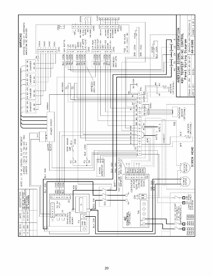
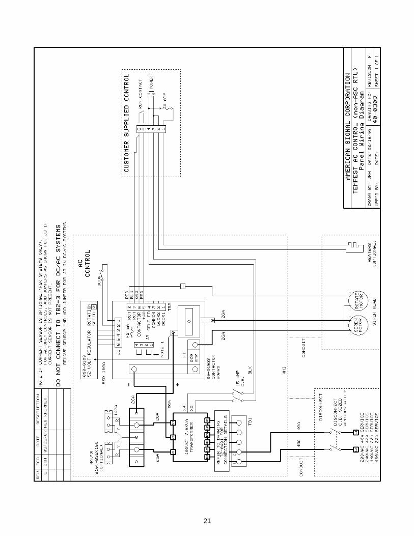
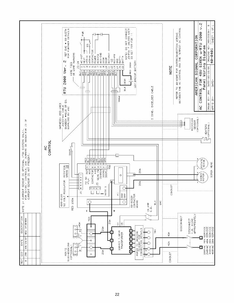
Disassembly, Repair, Replacement, and Reassemble 17 TROUBLE-SHOOTING CHECK LIST 18-19 DRAWINGS 20-30 AC/DC Control Wiring Diagram 20 AC Control Diagram w/o RTU 21 AC Control Diagram w/RTU 22 AC Transformer Mains connections 23 EM Controller Interconnect Diagram 24 DC/AC Harnesses Interconnect Diagram 25 Siren Logic (Power) Board Schematic 26 Contactor Board Schematic 27 DC Current Sensor Diagram 28 Tempest - Moscad Interface PCB 29 Tempest T-128 Exploded View 30 TEMPEST INTERNAL ROTATION SENSOR 31-35 PARTS LIST 36-42
3
GENERAL INFORMATION
Siren Unit: The Tempest T-128 is a 128 dB rotating directional electromechanical siren with a similar construction and operational design, which has been in production for over 50 years. For additional stability, Tempest T-128 is designed so the weight load is directly over the center of the pole. Communities, nuclear and other utilities, industry and petrochemical manufacturers, and the U.S. military use the Tempest T-128 siren for emergency warning. The 128dB rating is measured at 100 feet from siren based on FEMA Federal Emergency Management Guidelines. The model T-128 utilizes (2) individual motors to drive the sound producing components (approx. 500Hz) as well as the rotation RPM. Motors have factory sealed bearings to eliminate motor maintenance. All external surfaces are 3/16" fiberglass (minimum) or cast aluminum, eliminating sheet metal or stapled screens, which would rust. The T-128 siren maybe powered by DC battery (integral). AC/DC (rectified AC with battery back up), or on AC (utility) power only. With AC/DC version, AC provides primary power where as (integral) batteries provide secondary power (during primary outages). Battery version T-128 does also include battery chargers. The T-128 is designed for minimum current loads for high efficiency and extended component and battery life. American Signal designs all our equipment with high quality and reliability in mind. Siren Activation: The Model T-128-DC can be integrated into a larger system utilizing landline activation or radio control with appropriate control equipment. Controls are housed in lockable NEMA rated enclosures. Special cabinets are available on request: fiberglass, aluminum, corrosion-resistant. Rechargeable batteries are housed in separate enclosures, isolated from siren components. Vents keep corrosive fumes from areas of electronic components. From a central point, siren controls can be operated via radio through the use of central encoder connected to a transmitter. The transmitter relays activation codes to the siren location, where a decoder is interfaced with the siren control. The decoder receives and decodes the message to utilize signals. Two-way controls are also available, providing status feedback, as well as command only. Siren Installation: The T-128 should be mounted approximately 50 feet above ground per recommended mounting of location, see FEMA CPG1-17. Siren input power is described later in this document. The T-128 siren may be pole or roof mounted, and is shipped complete with (cog) eyebolt for lifting.
4
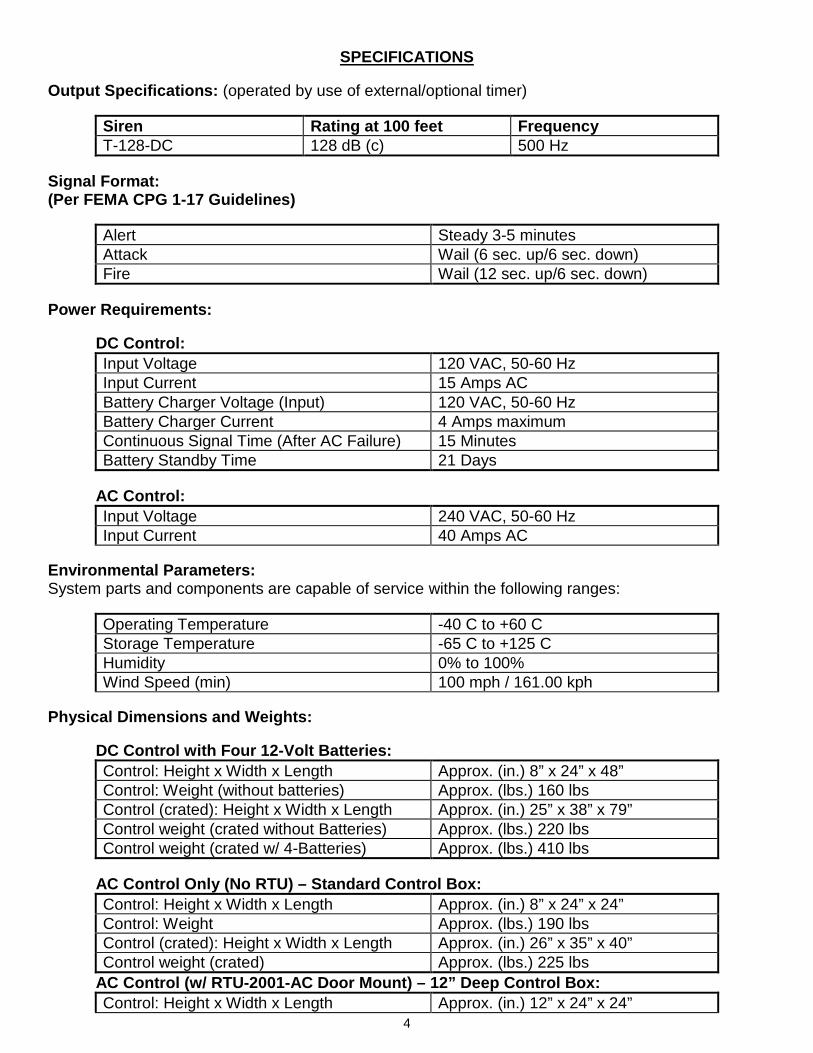
SPECIFICATIONS Output Specifications: (operated by use of external/optional timer)
Siren Rating at 100 feet Frequency T-128-DC 128 dB (c) 500 Hz
Signal Format: (Per FEMA CPG 1-17 Guidelines)
Alert Steady 3-5 minutes Attack Wail (6 sec. up/6 sec. down) Fire Wail (12 sec. up/6 sec. down)
Power Requirements: DC Control:
Input Voltage 120 VAC, 50-60 Hz Input Current 15 Amps AC Battery Charger Voltage (Input) 120 VAC, 50-60 Hz Battery Charger Current 4 Amps maximum Continuous Signal Time (After AC Failure) 15 Minutes Battery Standby Time 21 Days
AC Control:
Input Voltage 240 VAC, 50-60 Hz Input Current 40 Amps AC
Environmental Parameters: System parts and components are capable of service within the following ranges:
Operating Temperature -40 C to +60 C Storage Temperature -65 C to +125 C Humidity 0% to 100% Wind Speed (min) 100 mph / 161.00 kph
Physical Dimensions and Weights:
DC Control with Four 12-Volt Batteries: Control: Height x Width x Length Approx. (in.) 8” x 24” x 48” Control: Weight (without batteries) Approx. (lbs.) 160 lbs Control (crated): Height x Width x Length Approx. (in.) 25” x 38” x 79” Control weight (crated without Batteries) Approx. (lbs.) 220 lbs Control weight (crated w/ 4-Batteries) Approx. (lbs.) 410 lbs
AC Control Only (No RTU) – Standard Control Box: Control: Height x Width x Length Approx. (in.) 8” x 24” x 24” Control: Weight Approx. (lbs.) 190 lbs Control (crated): Height x Width x Length Approx. (in.) 26” x 35” x 40” Control weight (crated) Approx. (lbs.) 225 lbs
AC Control (w/ RTU-2001-AC Door Mount) – 12” Deep Control Box: Control: Height x Width x Length Approx. (in.) 12” x 24” x 24”
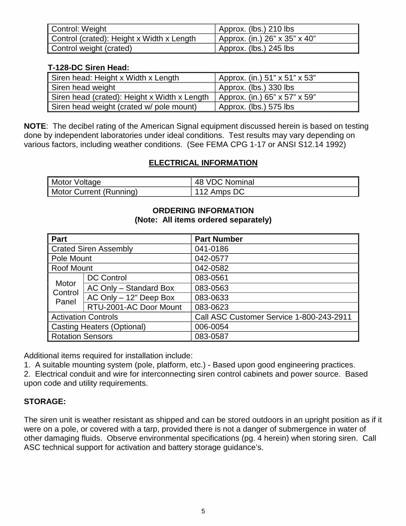
5
Control: Weight Approx. (lbs.) 210 lbs Control (crated): Height x Width x Length Approx. (in.) 26” x 35” x 40” Control weight (crated) Approx. (lbs.) 245 lbs
T-128-DC Siren Head: Siren head: Height x Width x Length Approx. (in.) 51” x 51” x 53” Siren head weight Approx. (lbs.) 330 lbs Siren head (crated): Height x Width x Length Approx. (in.) 65” x 57” x 59” Siren head weight (crated w/ pole mount) Approx. (lbs.) 575 lbs
NOTE: The decibel rating of the American Signal equipment discussed herein is based on testing done by independent laboratories under ideal conditions. Test results may vary depending on various factors, including weather conditions. (See FEMA CPG 1-17 or ANSI S12.14 1992)
ELECTRICAL INFORMATION
Motor Voltage 48 VDC Nominal Motor Current (Running) 112 Amps DC
ORDERING INFORMATION
(Note: All items ordered separately)
Part Part Number Crated Siren Assembly 041-0186 Pole Mount 042-0577 Roof Mount 042-0582
Motor Control Panel
DC Control 083-0561 AC Only – Standard Box 083-0563 AC Only – 12” Deep Box 083-0633 RTU-2001-AC Door Mount 083-0623
Activation Controls Call ASC Customer Service 1-800-243-2911 Casting Heaters (Optional) 006-0054 Rotation Sensors 083-0587
Additional items required for installation include: 1. A suitable mounting system (pole, platform, etc.) - Based upon good engineering practices. 2. Electrical conduit and wire for interconnecting siren control cabinets and power source. Based upon code and utility requirements.
STORAGE: The siren unit is weather resistant as shipped and can be stored outdoors in an upright position as if it were on a pole, or covered with a tarp, provided there is not a danger of submergence in water of other damaging fluids. Observe environmental specifications (pg. 4 herein) when storing siren. Call ASC technical support for activation and battery storage guidance’s.
6
INSTALLATION To ensure satisfactory operation and a safe and successful installation, careful consideration must be given to each of the following factors: 1. Safety precautions 2. Site selection for optimum signal coverage 3. Type of mounting 4. Power supply requirements 5. Provisions for servicing Safety Precautions: Qualified and experienced persons should attempt installation of the siren equipment only! When lifting the siren use a lifting device of adequate capacity. Do not use the siren eyebolt for lifting siren when it is attached to a mounting pole
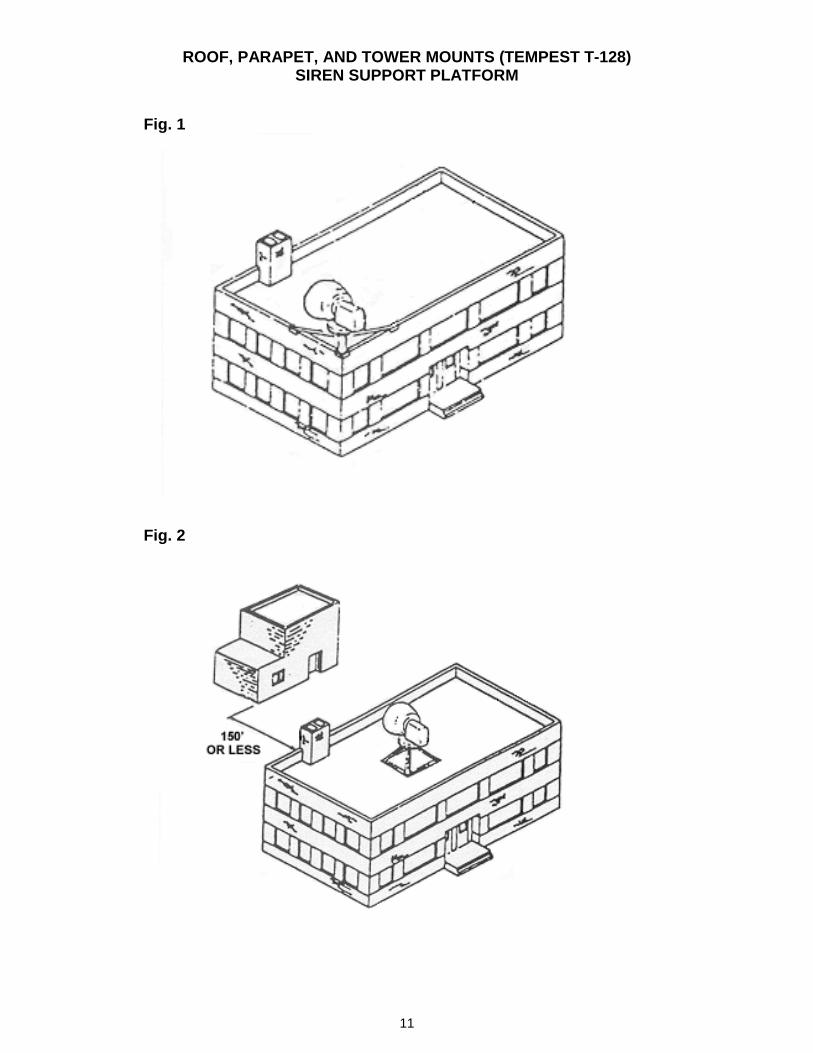
Always disconnect from power source including batteries before beginning any service or maintenance. All siren components should be pre-wired completely before connecting to the power source. Only qualified personnel should open the electrical control cabinet. Refer to wiring diagram and observe proper wiring procedure. Always advise others/occupants before testing siren unit. Ear protection must be worn when conducting any type of testing on the system!! Caution: Siren sound pressure is 128dB - 100 feet from siren. CAUTION!! EVERYONE IN THE VICINITY OF THE SIREN DURING TESTING SHOULD WEAR EAR PROTECTION DURING OPERATIONAL TESTS. FAILURE TO DO SO CAN CAUSE SEVERE HEARING DAMAGE. Site Selection and Types of Mounting: Careful consideration must be given in selecting a site or sites for installation. Locations should be plotted on local area maps to provide the desired coverage. A Systems Specialist should be consulted to determine the specific system requirements. See FEMA CPG 1-17. In lieu of a suitable existing structure for mounting, a Class II, cedar pole, approximately 50 feet long and sunk 8 feet deep is a generally acceptable mount (Mounting requirements may vary in certain areas, check local and state codes and customer specifications for the correct mounting structure). Refer to the illustrated mounting layouts for details. Figures 1, 2, 3 and 4 illustrate typical siren mounting arrangements see FEMA CPG 1-17 for specific mounting height recommendations. Electrical Power Requirements: An adequate 120/240 VAC, 15 amp power source for DC controls and a 40 amp for AC or AC/DC must be available at each siren site. The electrical installation must be in conformance with the project specifications, NEC, Federal, State and Local codes, and customer requirements - and should be in accordance with accepted industry
7
practice. All conduits for control panels must enter the bottom or side of the enclosures and be protected against environmental influences (rain, snow, etc.). Any conduit entering the top of the enclosure will void the siren warranty. Provisions for Servicing: As periodic service or maintenance may require use of high lift equipment, (and other service vehicles) caution must be exercised when planning site locations and site accessibility.
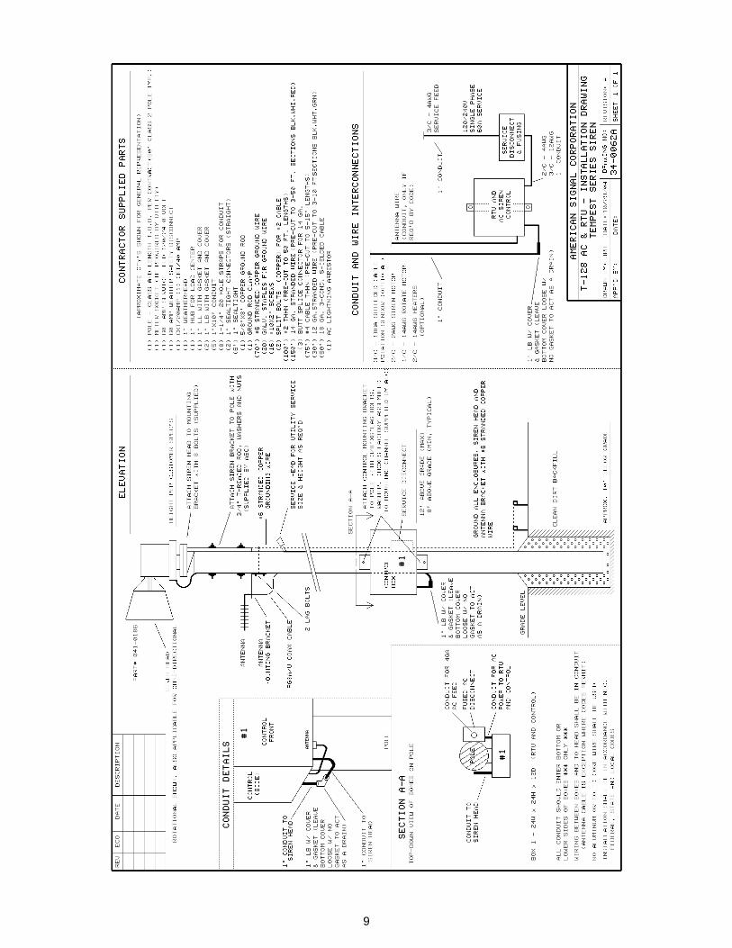
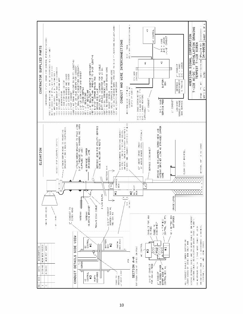
Mechanical Installation: The siren is provided with a mounting plate in the sheltered areas under the rotation mechanism. A matching plate must be fabricated as part of the siren mount. The plate must have eight equally spaced 9/16-inch holes on an 11-inch diameter circle. The siren is fastened to this plate by means of 1/2-inch stainless steel bolts, nuts, and lock washers. Pole mounting bracket is also available - see ordering information on page 5. Pole Mounts: The main requisite is the ability to properly support the weight and wind load of the siren assembly. When ordering, a specific type of mounting must be specified. When using a pole mount, an optional platform may be constructed at the proper work level. The electric control enclosure is usually mounted lower than the siren, but at least 8 feet above ground level to discourage vandalism. Locate the enclosure for easy accessibility by qualified personnel. If rungs or steps are provided for climbing up to the siren, it is advisable to locate the lowest step at least 10 feet above the ground to minimize the opportunity for vandalism. Lifting into Position When Siren is mounted to Pole: 1. If the siren is mounted to the pole, before lifting to the vertical position, the primary lift point must be the pole and not the eyebolt on the siren. Caution: Do not lift the entire siren and pole by the eyebolt on top of the siren motor and do not let any weight rest on the fiberglass parts of the siren. With the pole and siren in the final position, proceed with the electrical connections. 2. When the siren is separate from the pole or platform: The primary, lift point of the siren head unit (only) is the eyebolt located on top of the siren head. This eyebolt will support the entire siren unit safely only if in a vertical direction. Caution: Do not lift the unit in this way if attached to a pole or platform mount. When the siren is mounted in the final position, proceed with electrical connections.
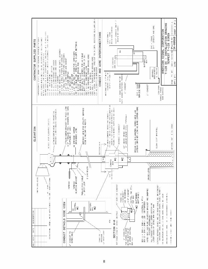
8
9
10
11
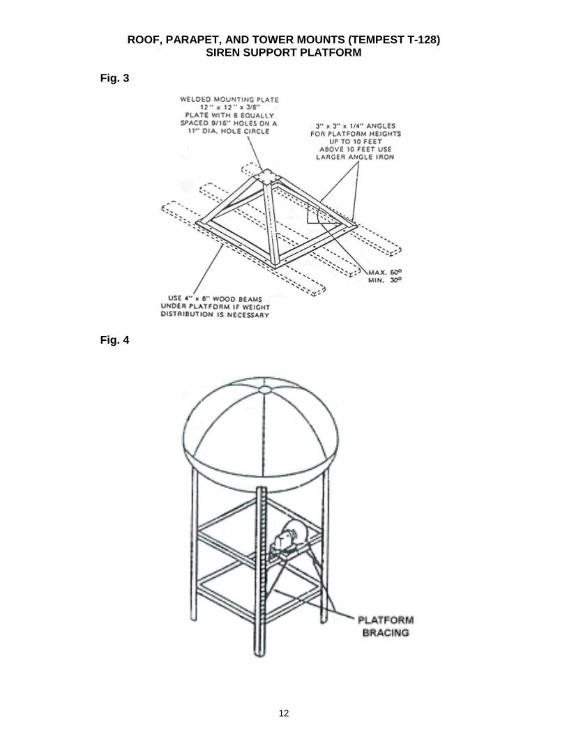
ROOF, PARAPET, AND TOWER MOUNTS (TEMPEST T-128) SIREN SUPPORT PLATFORM
Fig. 1
Fig. 2
12
ROOF, PARAPET, AND TOWER MOUNTS (TEMPEST T-128) SIREN SUPPORT PLATFORM
Fig. 3
Fig. 4
13
14
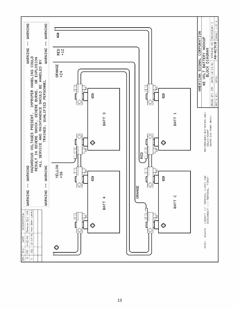
Electrical Controls/Siren Activation Electrical controls to operate the siren can be configured in several ways. However, for all installations there are four (4) main components required for a complete installation; 1. An adequate AC power supply from the local utility company, 2. The internal power supply provided by the system battery pack, 3. The siren motor control assembly through which battery power is supplied to the motor, and 4. The means of activation and associated equipment. The AC power from the local utility must be supplied to the siren equipment through an adequately fused disconnect switch (not supplied with siren). The method, type, number and location of the disconnect switch is dictated by local, state, and federal codes and customer requirements. However, a disconnect switch should also be provided. All batteries are mounted in a dedicated enclosure, which should be located directly below the motor control assembly for convenient wiring installation. Power cables and charging leads connect the batteries to the motor control assembly. The motor control assembly also supplies power to the siren via two #2 Awg. Power cables. The electrical controls needed for operating the siren are pre-wired and contained inside a separate NEMA rated weatherproof metal enclosure. The control enclosure should be mounted near the siren in a position of inaccessible to unauthorized persons. A mounting height of 10 feet above grade is recommended for pole-mounted sirens (as noted above). Install conduit between the control box and the siren, using wire adequate for the power requirements. All power and control wiring should be installed in conduit. NOTICE: Warranty will be voided if antenna wire or conduit enters the top of the control enclosure. Conduit, antennas and wires should always enter electrical control and junction boxes from the bottom or side to prevent leakage and water damage. Final Wiring and Testing: The siren unit motor leads terminate under the sheltered rotating mechanism for 1” (inch) conduit fitting. Proper starter and/or overload protection must be used to avoid damage to the siren electrical components. Refer to ELECTRICAL INFORMATION for amperage requirements. For ease of installation all wiring and continuity checks, with the exception of the batteries and the AC power connection, should be done prior to raising the pole. All interconnect wiring should be labeled and satisfactorily tested for continuity. Refer to system wiring diagrams for interconnect requirements. Batteries should be tested with a battery load tester before installing. After the siren and pole assembly are raised and set in place, the final battery connections and AC power connections can be made. Before proceeding turn the main power switch located inside the motor control panel to the off position. Then connect the batteries, connecting the positive leads first. Next connect the negative leads, leaving the main negative feed between the batteries and motor control cabinet as the very last lead to be connected.
At this time, AC power can be connected to the incoming side of the fused disconnect safety switch. After AC power is connected, the final negative lead can be connected to the battery. After making the final battery connection, the main switch can be closed and the safety switch turned on to start the battery charging circuit.
15
TEST AND START-UP
CAUTION!!!
Caution: Ear protection must be worn at all times, to prevent hearing damage when the siren is operated. Siren produces 128dB spl at 100 feet. Testing: A. Siren unit, motor controller and batteries/chargers: Before attempting to start or test the siren, check the following: B. Final check all bolted or assembled components After continuity checks have been completed, the battery connections made, and AC power applied to the system, the charging current should be verified from the green power LED located on the chargers. The charging current may vary depending on the condition of the battery at the time of installation; however, once fully charged the current should drop to approximately 0.2 amps to 1 amp. Once the batteries are fully charged, voltage checks can be made to verify proper voltage has been obtained. To do so measure the voltage across the negative distribution block terminals and the number 4 charger lead in the motor control assembly, which should be a nominal 52.5 to 54 VDC under charge. If not, disconnect the chargers from the circuit by opening the main switch in the motor contactor assembly. Measure the voltage across each battery one at a time, with a digital voltmeter; static battery voltage should be a nominal 13.6-14.2 VDC (across each battery). If batteries are below 12.2 volts use battery load tester to check condition of battery before completing start-up procedures. CAUTION: THE FOLLOWING TEST WILL CAUSE THE SIREN TO OPERATE MOMENTARILY. EAR PROTECTION MUST BE WORN TO AVOID HEARING DAMAGE.
Momentarily press and hold the test button for one second inside the motor control assembly, causing the siren motor to start. Read the voltage across the batteries, listening and looking to ensure the siren motor has started to sound and rotate. The battery voltage should not drop significantly under test load condition.
Note: The contact closure should be maintained for no less than 2 seconds to avoid damage from inductive forces. The test of the siren and siren controller is now complete. Testing of the activation interface can now be done.
16
SIREN ACTIVATION Siren activation options include, direct switch control, remote radio control, or operation via telephone lines - depending upon specific needs. Having determined the specific siren activation means, connect the signal source wires to the control cabinet terminal blocks (Refer to activation wiring diagrams). Proceed to test the entire operation of the siren using the radio controls, timer or telephone system according to activation equipment documentation. OPERATION The T-48-DC control is designed for universal application. Activation may be by means of remote direct-wired lines, telephone lines and relays or special radio controls. The activating and timing of equipment is to be provided by the procurement agency at time of installation. This manual will not attempt to define the exact operational procedure of the siren. Activation equipment documentation provided separately (Contact ASC technical support at 800-243-2911)
17
MAINTENANCE
CAUTION!!! DISCONNECT POWER BEFORE PERFORMING MECHANICAL MAINTENANCE. Inspection Typically, sirens operate only in emergency situations, and therefore, very little operational wear is to be anticipated. Periodic operational tests should be made to verify functionality. The frequency of testing can vary annually. Once every six months, or at other optional intervals as required. Perform the following inspections: 1. Inspect external fiberglass surfaces for any physical damage. 2. Inspect screened openings to determine that they are unobstructed and that screens are securely fastened. 3. Inspect control panel door gasket and interior to determine that no water leakage exists. 4. Check batteries. Load test each battery individually. Check fluid levels. Add water and / or electrolyte to proper level. Disassembly, Repair, Replacement and Reassemble The siren's physical design is such that it precludes most mechanical problems other than those caused by natural disasters or violent physical damage. The siren configuration is constructed from reinforced fiberglass and bolted together to form a weather-resistant enclosure for all moving parts. The parts drawings illustrate component placement. Upon removal of the fiberglass hood, all working parts are exposed to view. Disassembly procedures are extremely simple and ordinary mechanics tools are adequate for service work.
18
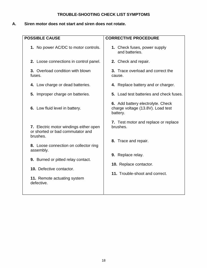
TROUBLE-SHOOTING CHECK LIST SYMPTOMS A. Siren motor does not start and siren does not rotate.
POSSIBLE CAUSE
1. No power AC/DC to motor controls. 2. Loose connections in control panel.
3. Overload condition with blown fuses.
4. Low charge or dead batteries.
5. Improper charge on batteries.
6. Low fluid level in battery.
7. Electric motor windings either open or shorted or bad commutator and brushes. 8. Loose connection on collector ring assembly. 9. Burned or pitted relay contact.
10. Defective contactor.
11. Remote actuating system defective.
CORRECTIVE PROCEDURE
1. Check fuses, power supply and batteries. 2. Check and repair.
3. Trace overload and correct the cause.
4. Replace battery and or charger.
5. Load test batteries and check fuses.
6. Add battery electrolyte. Check charge voltage (13.8V). Load test battery.
7. Test motor and replace or replace brushes.
8. Trace and repair. 9. Replace relay. 10. Replace contactor.
11. Trouble-shoot and correct.
19
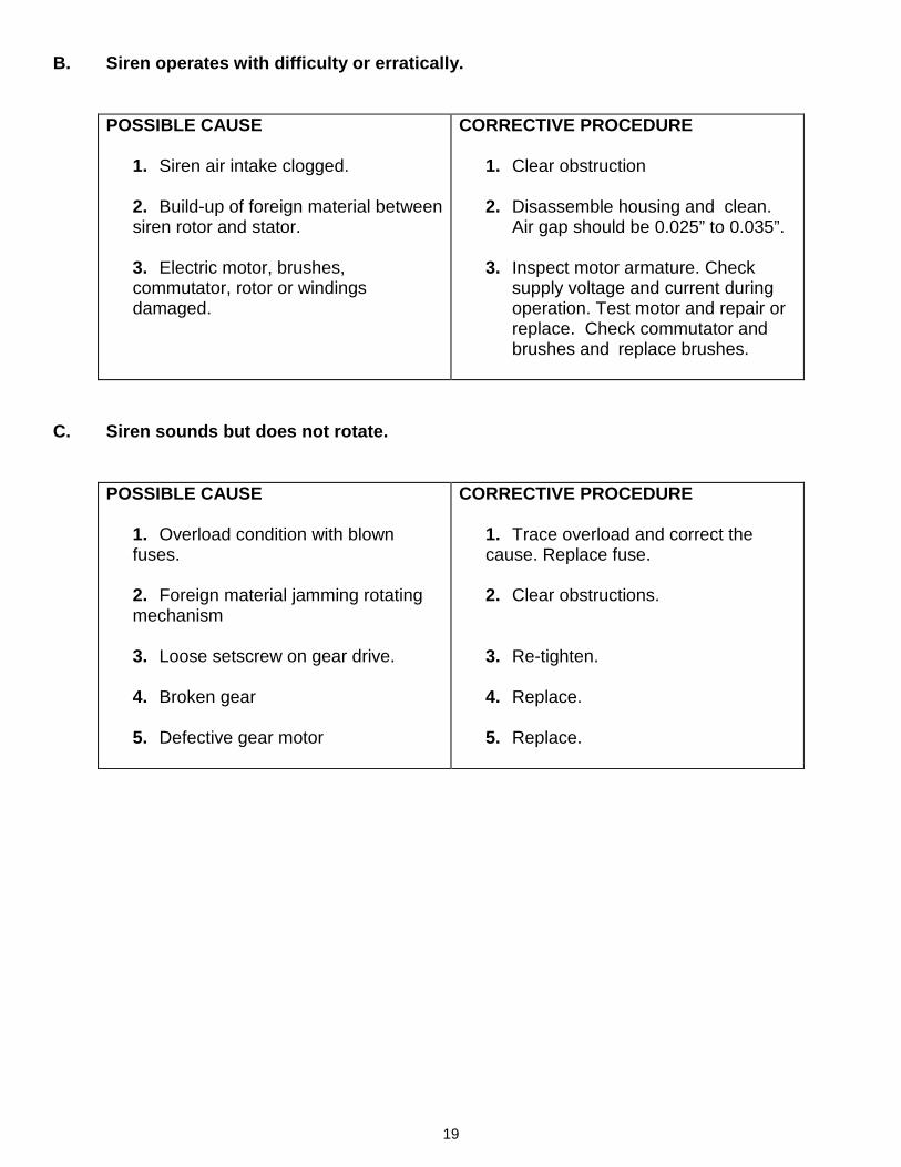
B. Siren operates with difficulty or erratically.
POSSIBLE CAUSE
1. Siren air intake clogged.
2. Build-up of foreign material between siren rotor and stator.
3. Electric motor, brushes, commutator, rotor or windings damaged.
CORRECTIVE PROCEDURE
1. Clear obstruction 2. Disassemble housing and clean.
Air gap should be 0.025” to 0.035”.
3. Inspect motor armature. Check supply voltage and current during operation. Test motor and repair or replace. Check commutator and brushes and replace brushes.
C. Siren sounds but does not rotate.
POSSIBLE CAUSE
1. Overload condition with blown fuses. 2. Foreign material jamming rotating mechanism 3. Loose setscrew on gear drive. 4. Broken gear 5. Defective gear motor
CORRECTIVE PROCEDURE
1. Trace overload and correct the cause. Replace fuse. 2. Clear obstructions. 3. Re-tighten. 4. Replace. 5. Replace.
20
21
22
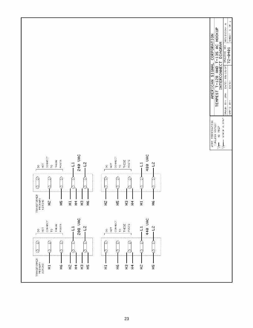
23
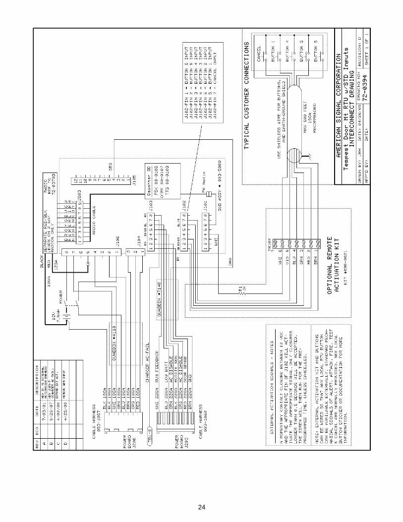
24
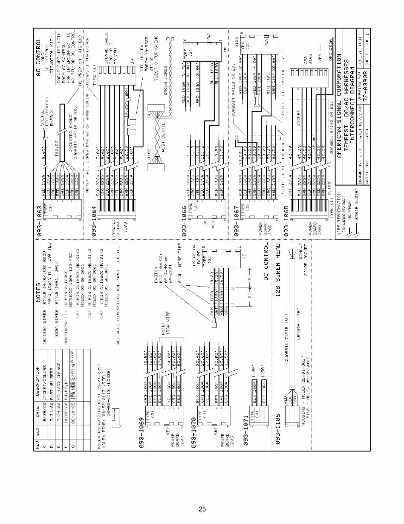
25
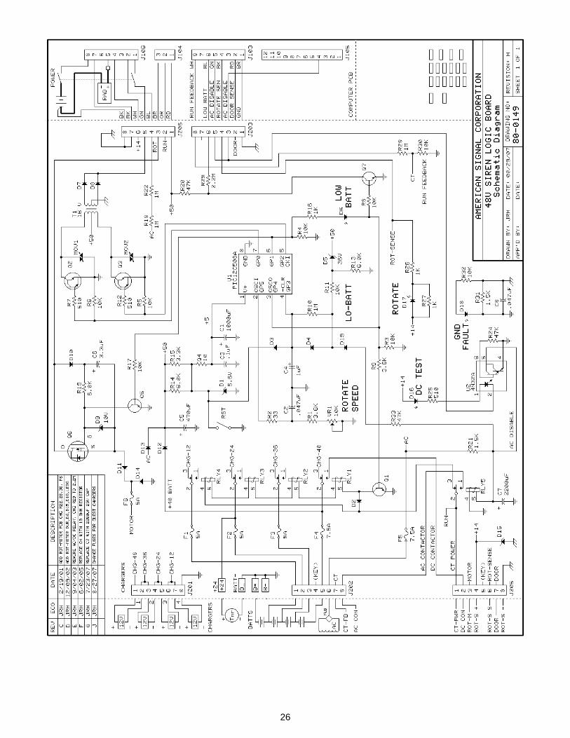
26
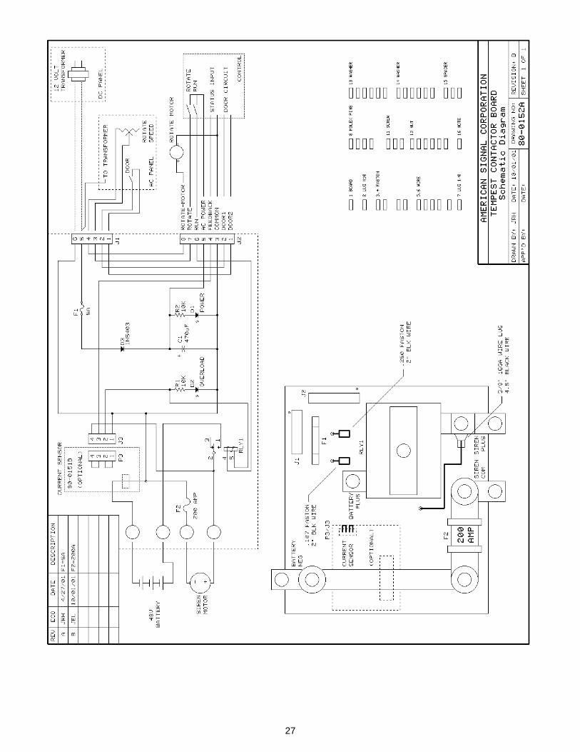
27
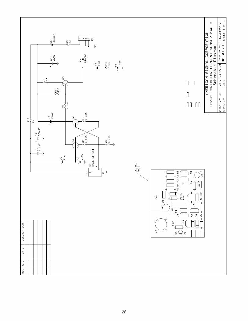
28
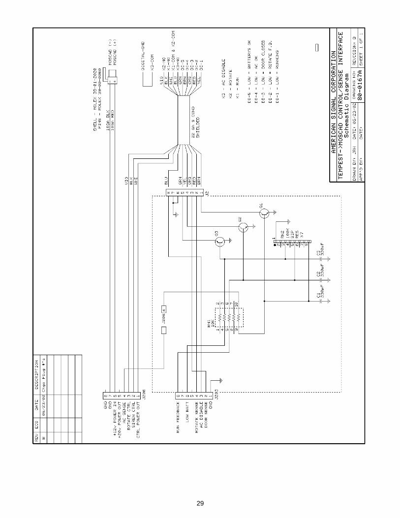
29

30
31
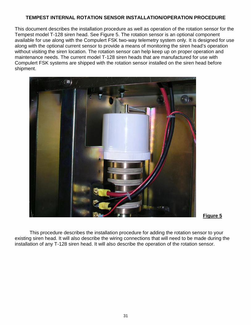
TEMPEST INTERNAL ROTATION SENSOR INSTALLATION/OPERATION PROCEDURE This document describes the installation procedure as well as operation of the rotation sensor for the Tempest model T-128 siren head. See Figure 5. The rotation sensor is an optional component available for use along with the Compulert FSK two-way telemetry system only. It is designed for use along with the optional current sensor to provide a means of monitoring the siren head’s operation without visiting the siren location. The rotation sensor can help keep up on proper operation and maintenance needs. The current model T-128 siren heads that are manufactured for use with Compulert FSK systems are shipped with the rotation sensor installed on the siren head before shipment.
Figure 5 This procedure describes the installation procedure for adding the rotation sensor to your existing siren head. It will also describe the wiring connections that will need to be made during the installation of any T-128 siren head. It will also describe the operation of the rotation sensor.
32
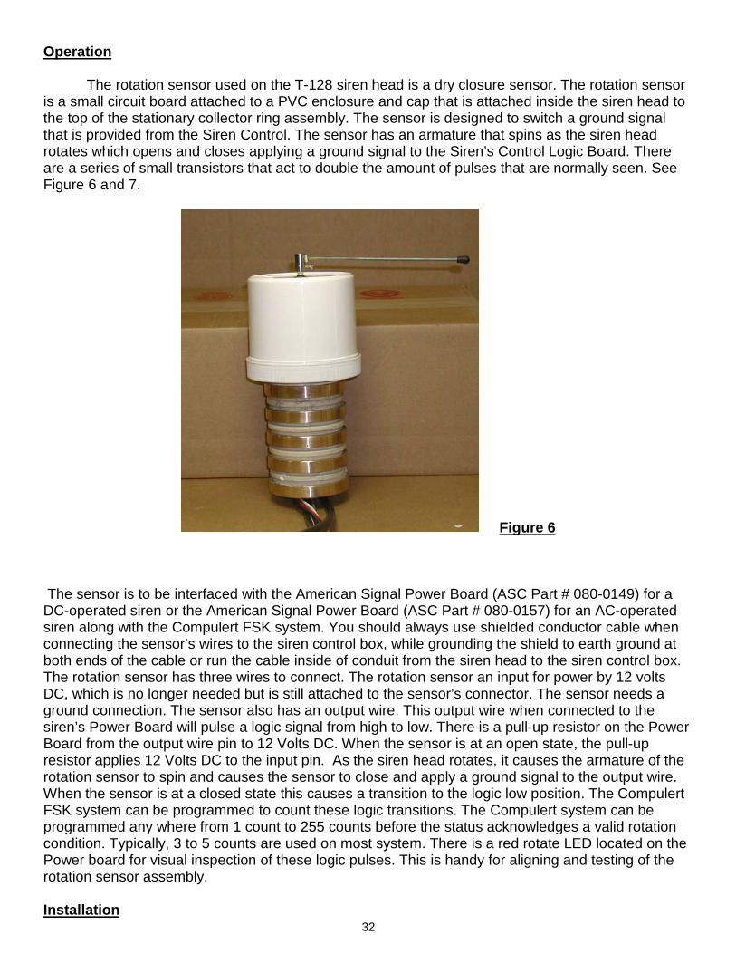
Operation The rotation sensor used on the T-128 siren head is a dry closure sensor. The rotation sensor is a small circuit board attached to a PVC enclosure and cap that is attached inside the siren head to the top of the stationary collector ring assembly. The sensor is designed to switch a ground signal that is provided from the Siren Control. The sensor has an armature that spins as the siren head rotates which opens and closes applying a ground signal to the Siren’s Control Logic Board. There are a series of small transistors that act to double the amount of pulses that are normally seen. See Figure 6 and 7.
Figure 6 The sensor is to be interfaced with the American Signal Power Board (ASC Part # 080-0149) for a DC-operated siren or the American Signal Power Board (ASC Part # 080-0157) for an AC-operated siren along with the Compulert FSK system. You should always use shielded conductor cable when connecting the sensor’s wires to the siren control box, while grounding the shield to earth ground at both ends of the cable or run the cable inside of conduit from the siren head to the siren control box. The rotation sensor has three wires to connect. The rotation sensor an input for power by 12 volts DC, which is no longer needed but is still attached to the sensor’s connector. The sensor needs a ground connection. The sensor also has an output wire. This output wire when connected to the siren’s Power Board will pulse a logic signal from high to low. There is a pull-up resistor on the Power Board from the output wire pin to 12 Volts DC. When the sensor is at an open state, the pull-up resistor applies 12 Volts DC to the input pin. As the siren head rotates, it causes the armature of the rotation sensor to spin and causes the sensor to close and apply a ground signal to the output wire. When the sensor is at a closed state this causes a transition to the logic low position. The Compulert FSK system can be programmed to count these logic transitions. The Compulert system can be programmed any where from 1 count to 255 counts before the status acknowledges a valid rotation condition. Typically, 3 to 5 counts are used on most system. There is a red rotate LED located on the Power board for visual inspection of these logic pulses. This is handy for aligning and testing of the rotation sensor assembly. Installation
33
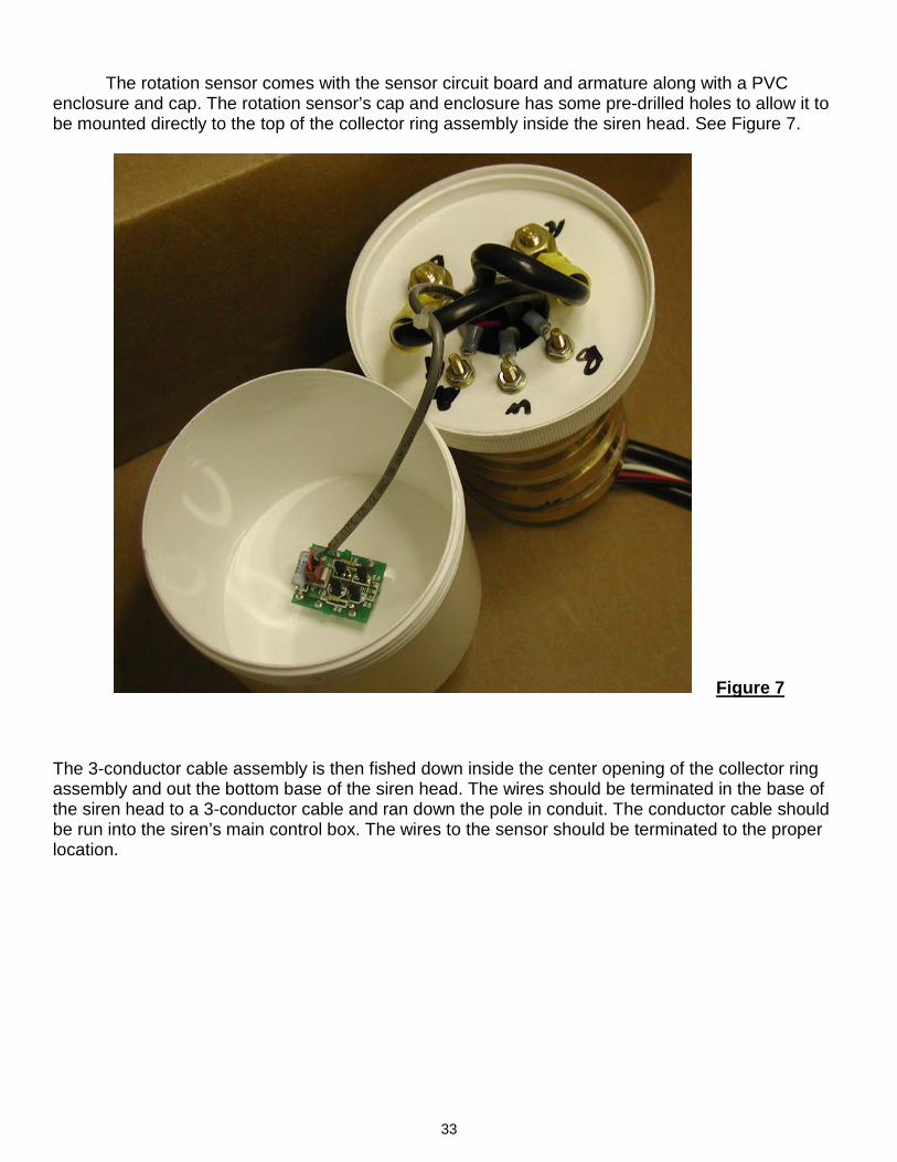
The rotation sensor comes with the sensor circuit board and armature along with a PVC enclosure and cap. The rotation sensor’s cap and enclosure has some pre-drilled holes to allow it to be mounted directly to the top of the collector ring assembly inside the siren head. See Figure 7.
Figure 7 The 3-conductor cable assembly is then fished down inside the center opening of the collector ring assembly and out the bottom base of the siren head. The wires should be terminated in the base of the siren head to a 3-conductor cable and ran down the pole in conduit. The conductor cable should be run into the siren’s main control box. The wires to the sensor should be terminated to the proper location.
34
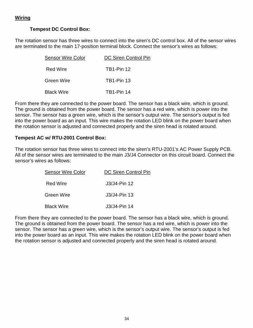
Wiring Tempest DC Control Box: The rotation sensor has three wires to connect into the siren’s DC control box. All of the sensor wires are terminated to the main 17-position terminal block. Connect the sensor’s wires as follows: Sensor Wire Color DC Siren Control Pin Red Wire TB1-Pin 12 Green Wire TB1-Pin 13 Black Wire TB1-Pin 14 From there they are connected to the power board. The sensor has a black wire, which is ground. The ground is obtained from the power board. The sensor has a red wire, which is power into the sensor. The sensor has a green wire, which is the sensor’s output wire. The sensor’s output is fed into the power board as an input. This wire makes the rotation LED blink on the power board when the rotation sensor is adjusted and connected properly and the siren head is rotated around. Tempest AC w/ RTU-2001 Control Box: The rotation sensor has three wires to connect into the siren’s RTU-2001’s AC Power Supply PCB. All of the sensor wires are terminated to the main J3/J4 Connector on this circuit board. Connect the sensor’s wires as follows: Sensor Wire Color DC Siren Control Pin Red Wire J3/J4-Pin 12 Green Wire J3/J4-Pin 13 Black Wire J3/J4-Pin 14 From there they are connected to the power board. The sensor has a black wire, which is ground. The ground is obtained from the power board. The sensor has a red wire, which is power into the sensor. The sensor has a green wire, which is the sensor’s output wire. The sensor’s output is fed into the power board as an input. This wire makes the rotation LED blink on the power board when the rotation sensor is adjusted and connected properly and the siren head is rotated around.
35
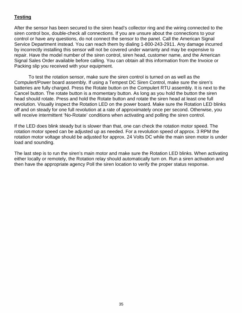
Testing After the sensor has been secured to the siren head’s collector ring and the wiring connected to the siren control box, double-check all connections. If you are unsure about the connections to your control or have any questions, do not connect the sensor to the panel. Call the American Signal Service Department instead. You can reach them by dialing 1-800-243-2911. Any damage incurred by incorrectly installing this sensor will not be covered under warranty and may be expensive to repair. Have the model number of the siren control, siren head, customer name, and the American Signal Sales Order available before calling. You can obtain all this information from the Invoice or Packing slip you received with your equipment. To test the rotation sensor, make sure the siren control is turned on as well as the Compulert/Power board assembly. If using a Tempest DC Siren Control, make sure the siren’s batteries are fully charged. Press the Rotate button on the Compulert RTU assembly. It is next to the Cancel button. The rotate button is a momentary button. As long as you hold the button the siren head should rotate. Press and hold the Rotate button and rotate the siren head at least one full revolution. Visually inspect the Rotation LED on the power board. Make sure the Rotation LED blinks off and on steady for one full revolution at a rate of approximately once per second. Otherwise, you will receive intermittent ‘No-Rotate’ conditions when activating and polling the siren control. If the LED does blink steady but is slower than that, one can check the rotation motor speed. The rotation motor speed can be adjusted up as needed. For a revolution speed of approx. 3 RPM the rotation motor voltage should be adjusted for approx. 24 Volts DC while the main siren motor is under load and sounding. The last step is to run the siren’s main motor and make sure the Rotation LED blinks. When activating either locally or remotely, the Rotation relay should automatically turn on. Run a siren activation and then have the appropriate agency Poll the siren location to verify the proper status response.
36
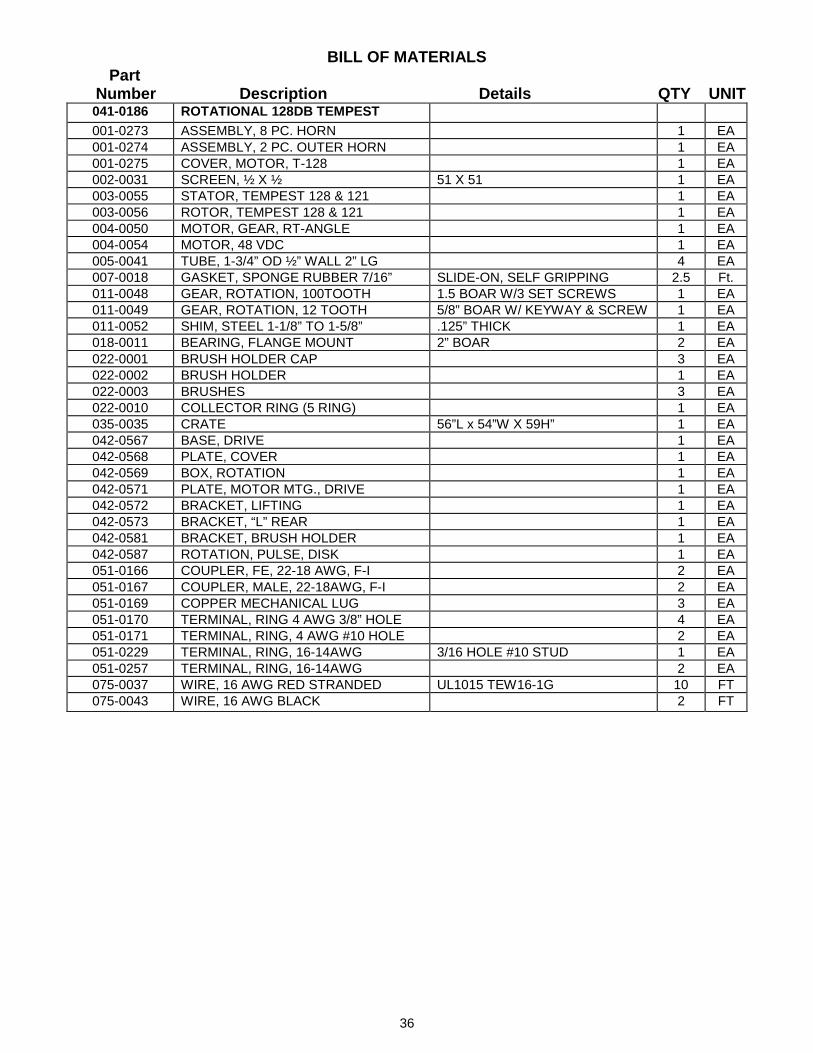
BILL OF MATERIALS Part Number Description Details QTY UNIT 041-0186 ROTATIONAL 128DB TEMPEST 001-0273 ASSEMBLY, 8 PC. HORN 1 EA 001-0274 ASSEMBLY, 2 PC. OUTER HORN 1 EA 001-0275 COVER, MOTOR, T-128 1 EA 002-0031 SCREEN, ½ X ½ 51 X 51 1 EA 003-0055 STATOR, TEMPEST 128 & 121 1 EA 003-0056 ROTOR, TEMPEST 128 & 121 1 EA 004-0050 MOTOR, GEAR, RT-ANGLE 1 EA 004-0054 MOTOR, 48 VDC 1 EA 005-0041 TUBE, 1-3/4” OD ½” WALL 2” LG 4 EA 007-0018 GASKET, SPONGE RUBBER 7/16” SLIDE-ON, SELF GRIPPING 2.5 Ft. 011-0048 GEAR, ROTATION, 100TOOTH 1.5 BOAR W/3 SET SCREWS 1 EA 011-0049 GEAR, ROTATION, 12 TOOTH 5/8” BOAR W/ KEYWAY & SCREW 1 EA 011-0052 SHIM, STEEL 1-1/8” TO 1-5/8” .125” THICK 1 EA 018-0011 BEARING, FLANGE MOUNT 2” BOAR 2 EA 022-0001 BRUSH HOLDER CAP 3 EA 022-0002 BRUSH HOLDER 1 EA 022-0003 BRUSHES 3 EA 022-0010 COLLECTOR RING (5 RING) 1 EA 035-0035 CRATE 56”L x 54”W X 59H” 1 EA 042-0567 BASE, DRIVE 1 EA 042-0568 PLATE, COVER 1 EA 042-0569 BOX, ROTATION 1 EA 042-0571 PLATE, MOTOR MTG., DRIVE 1 EA 042-0572 BRACKET, LIFTING 1 EA 042-0573 BRACKET, “L” REAR 1 EA 042-0581 BRACKET, BRUSH HOLDER 1 EA 042-0587 ROTATION, PULSE, DISK 1 EA 051-0166 COUPLER, FE, 22-18 AWG, F-I 2 EA 051-0167 COUPLER, MALE, 22-18AWG, F-I 2 EA 051-0169 COPPER MECHANICAL LUG 3 EA 051-0170 TERMINAL, RING 4 AWG 3/8” HOLE 4 EA 051-0171 TERMINAL, RING, 4 AWG #10 HOLE 2 EA 051-0229 TERMINAL, RING, 16-14AWG 3/16 HOLE #10 STUD 1 EA 051-0257 TERMINAL, RING, 16-14AWG 2 EA 075-0037 WIRE, 16 AWG RED STRANDED UL1015 TEW16-1G 10 FT 075-0043 WIRE, 16 AWG BLACK 2 FT
37
Part Number Description Details QTY UNIT
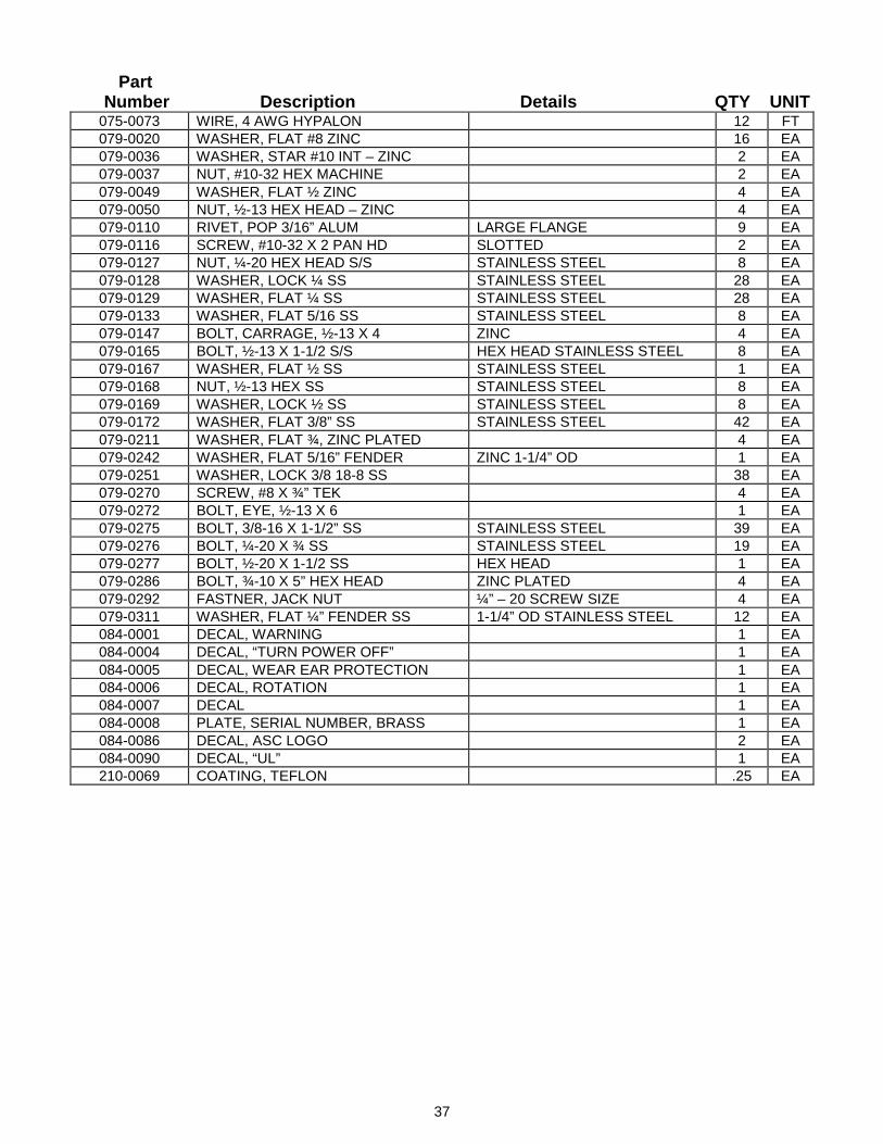
075-0073 WIRE, 4 AWG HYPALON 12 FT 079-0020 WASHER, FLAT #8 ZINC 16 EA 079-0036 WASHER, STAR #10 INT – ZINC 2 EA 079-0037 NUT, #10-32 HEX MACHINE 2 EA 079-0049 WASHER, FLAT ½ ZINC 4 EA 079-0050 NUT, ½-13 HEX HEAD – ZINC 4 EA 079-0110 RIVET, POP 3/16” ALUM LARGE FLANGE 9 EA 079-0116 SCREW, #10-32 X 2 PAN HD SLOTTED 2 EA 079-0127 NUT, ¼-20 HEX HEAD S/S STAINLESS STEEL 8 EA 079-0128 WASHER, LOCK ¼ SS STAINLESS STEEL 28 EA 079-0129 WASHER, FLAT ¼ SS STAINLESS STEEL 28 EA 079-0133 WASHER, FLAT 5/16 SS STAINLESS STEEL 8 EA 079-0147 BOLT, CARRAGE, ½-13 X 4 ZINC 4 EA 079-0165 BOLT, ½-13 X 1-1/2 S/S HEX HEAD STAINLESS STEEL 8 EA 079-0167 WASHER, FLAT ½ SS STAINLESS STEEL 1 EA 079-0168 NUT, ½-13 HEX SS STAINLESS STEEL 8 EA 079-0169 WASHER, LOCK ½ SS STAINLESS STEEL 8 EA 079-0172 WASHER, FLAT 3/8” SS STAINLESS STEEL 42 EA 079-0211 WASHER, FLAT ¾, ZINC PLATED 4 EA 079-0242 WASHER, FLAT 5/16” FENDER ZINC 1-1/4” OD 1 EA 079-0251 WASHER, LOCK 3/8 18-8 SS 38 EA 079-0270 SCREW, #8 X ¾” TEK 4 EA 079-0272 BOLT, EYE, ½-13 X 6 1 EA 079-0275 BOLT, 3/8-16 X 1-1/2” SS STAINLESS STEEL 39 EA 079-0276 BOLT, ¼-20 X ¾ SS STAINLESS STEEL 19 EA 079-0277 BOLT, ½-20 X 1-1/2 SS HEX HEAD 1 EA 079-0286 BOLT, ¾-10 X 5” HEX HEAD ZINC PLATED 4 EA 079-0292 FASTNER, JACK NUT ¼” – 20 SCREW SIZE 4 EA 079-0311 WASHER, FLAT ¼” FENDER SS 1-1/4” OD STAINLESS STEEL 12 EA 084-0001 DECAL, WARNING 1 EA 084-0004 DECAL, “TURN POWER OFF” 1 EA 084-0005 DECAL, WEAR EAR PROTECTION 1 EA 084-0006 DECAL, ROTATION 1 EA 084-0007 DECAL 1 EA 084-0008 PLATE, SERIAL NUMBER, BRASS 1 EA 084-0086 DECAL, ASC LOGO 2 EA 084-0090 DECAL, “UL” 1 EA 210-0069 COATING, TEFLON .25 EA
38
Part Number Description Details QTY UNIT
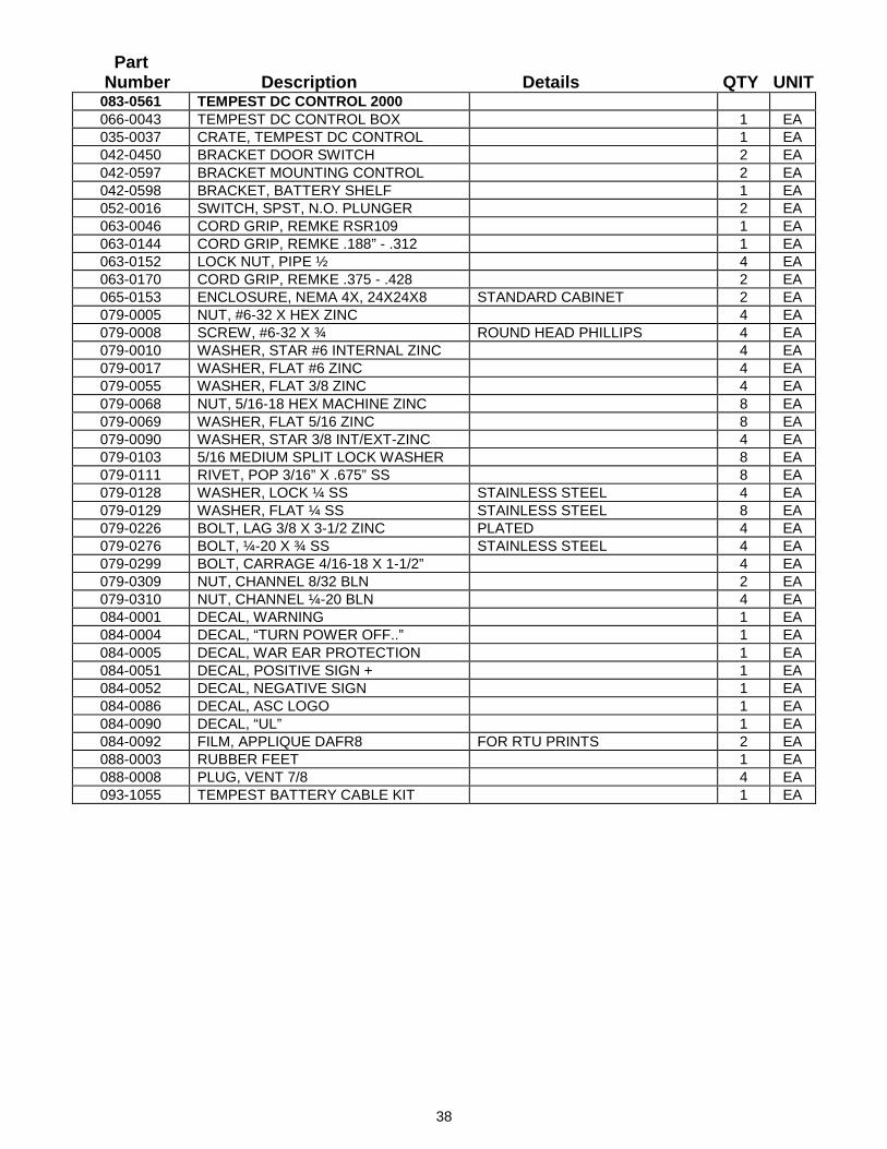
083-0561 TEMPEST DC CONTROL 2000 066-0043 TEMPEST DC CONTROL BOX 1 EA 035-0037 CRATE, TEMPEST DC CONTROL 1 EA 042-0450 BRACKET DOOR SWITCH 2 EA 042-0597 BRACKET MOUNTING CONTROL 2 EA 042-0598 BRACKET, BATTERY SHELF 1 EA 052-0016 SWITCH, SPST, N.O. PLUNGER 2 EA 063-0046 CORD GRIP, REMKE RSR109 1 EA 063-0144 CORD GRIP, REMKE .188” - .312 1 EA 063-0152 LOCK NUT, PIPE ½ 4 EA 063-0170 CORD GRIP, REMKE .375 - .428 2 EA 065-0153 ENCLOSURE, NEMA 4X, 24X24X8 STANDARD CABINET 2 EA 079-0005 NUT, #6-32 X HEX ZINC 4 EA 079-0008 SCREW, #6-32 X ¾ ROUND HEAD PHILLIPS 4 EA 079-0010 WASHER, STAR #6 INTERNAL ZINC 4 EA 079-0017 WASHER, FLAT #6 ZINC 4 EA 079-0055 WASHER, FLAT 3/8 ZINC 4 EA 079-0068 NUT, 5/16-18 HEX MACHINE ZINC 8 EA 079-0069 WASHER, FLAT 5/16 ZINC 8 EA 079-0090 WASHER, STAR 3/8 INT/EXT-ZINC 4 EA 079-0103 5/16 MEDIUM SPLIT LOCK WASHER 8 EA 079-0111 RIVET, POP 3/16” X .675” SS 8 EA 079-0128 WASHER, LOCK ¼ SS STAINLESS STEEL 4 EA 079-0129 WASHER, FLAT ¼ SS STAINLESS STEEL 8 EA 079-0226 BOLT, LAG 3/8 X 3-1/2 ZINC PLATED 4 EA 079-0276 BOLT, ¼-20 X ¾ SS STAINLESS STEEL 4 EA 079-0299 BOLT, CARRAGE 4/16-18 X 1-1/2” 4 EA 079-0309 NUT, CHANNEL 8/32 BLN 2 EA 079-0310 NUT, CHANNEL ¼-20 BLN 4 EA 084-0001 DECAL, WARNING 1 EA 084-0004 DECAL, “TURN POWER OFF..” 1 EA 084-0005 DECAL, WAR EAR PROTECTION 1 EA 084-0051 DECAL, POSITIVE SIGN + 1 EA 084-0052 DECAL, NEGATIVE SIGN 1 EA 084-0086 DECAL, ASC LOGO 1 EA 084-0090 DECAL, “UL” 1 EA 084-0092 FILM, APPLIQUE DAFR8 FOR RTU PRINTS 2 EA 088-0003 RUBBER FEET 1 EA 088-0008 PLUG, VENT 7/8 4 EA 093-1055 TEMPEST BATTERY CABLE KIT 1 EA
39
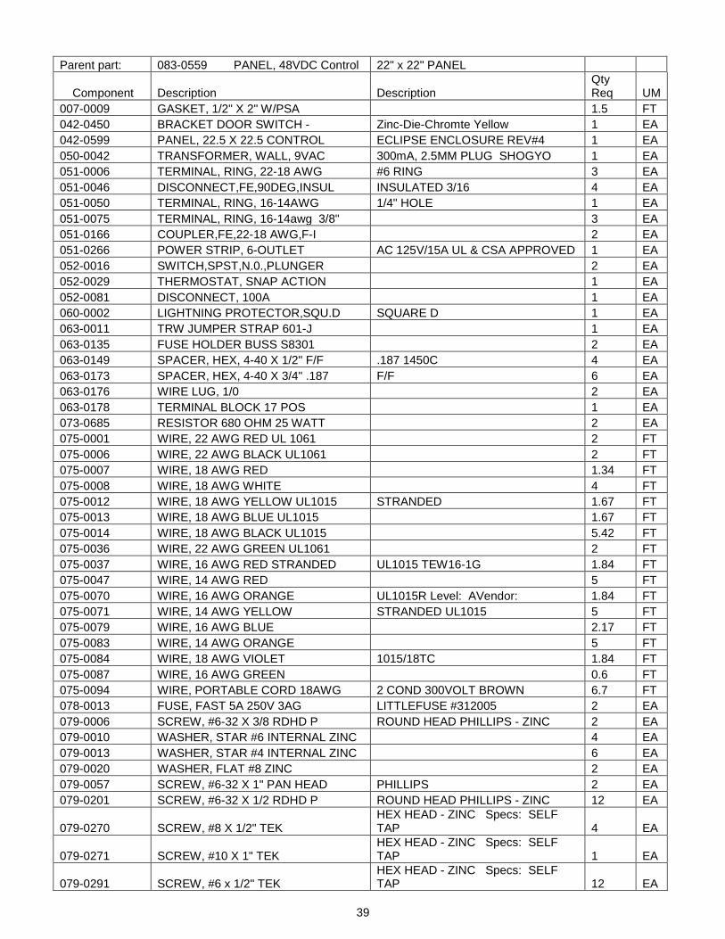
Parent part: 083-0559 PANEL, 48VDC Control 22" x 22" PANEL
Component Description Description Qty Req UM
007-0009 GASKET, 1/2" X 2" W/PSA 1.5 FT 042-0450 BRACKET DOOR SWITCH - Zinc-Die-Chromte Yellow 1 EA 042-0599 PANEL, 22.5 X 22.5 CONTROL ECLIPSE ENCLOSURE REV#4 1 EA 050-0042 TRANSFORMER, WALL, 9VAC 300mA, 2.5MM PLUG SHOGYO 1 EA 051-0006 TERMINAL, RING, 22-18 AWG #6 RING 3 EA 051-0046 DISCONNECT,FE,90DEG,INSUL INSULATED 3/16 4 EA 051-0050 TERMINAL, RING, 16-14AWG 1/4" HOLE 1 EA 051-0075 TERMINAL, RING, 16-14awg 3/8" 3 EA 051-0166 COUPLER,FE,22-18 AWG,F-I 2 EA 051-0266 POWER STRIP, 6-OUTLET AC 125V/15A UL & CSA APPROVED 1 EA 052-0016 SWITCH,SPST,N.0.,PLUNGER 2 EA 052-0029 THERMOSTAT, SNAP ACTION 1 EA 052-0081 DISCONNECT, 100A 1 EA 060-0002 LIGHTNING PROTECTOR,SQU.D SQUARE D 1 EA 063-0011 TRW JUMPER STRAP 601-J 1 EA 063-0135 FUSE HOLDER BUSS S8301 2 EA 063-0149 SPACER, HEX, 4-40 X 1/2" F/F .187 1450C 4 EA 063-0173 SPACER, HEX, 4-40 X 3/4" .187 F/F 6 EA 063-0176 WIRE LUG, 1/0 2 EA 063-0178 TERMINAL BLOCK 17 POS 1 EA 073-0685 RESISTOR 680 OHM 25 WATT 2 EA 075-0001 WIRE, 22 AWG RED UL 1061 2 FT 075-0006 WIRE, 22 AWG BLACK UL1061 2 FT 075-0007 WIRE, 18 AWG RED 1.34 FT 075-0008 WIRE, 18 AWG WHITE 4 FT 075-0012 WIRE, 18 AWG YELLOW UL1015 STRANDED 1.67 FT 075-0013 WIRE, 18 AWG BLUE UL1015 1.67 FT 075-0014 WIRE, 18 AWG BLACK UL1015 5.42 FT 075-0036 WIRE, 22 AWG GREEN UL1061 2 FT 075-0037 WIRE, 16 AWG RED STRANDED UL1015 TEW16-1G 1.84 FT 075-0047 WIRE, 14 AWG RED 5 FT 075-0070 WIRE, 16 AWG ORANGE UL1015R Level: AVendor: 1.84 FT 075-0071 WIRE, 14 AWG YELLOW STRANDED UL1015 5 FT 075-0079 WIRE, 16 AWG BLUE 2.17 FT 075-0083 WIRE, 14 AWG ORANGE 5 FT 075-0084 WIRE, 18 AWG VIOLET 1015/18TC 1.84 FT 075-0087 WIRE, 16 AWG GREEN 0.6 FT 075-0094 WIRE, PORTABLE CORD 18AWG 2 COND 300VOLT BROWN 6.7 FT 078-0013 FUSE, FAST 5A 250V 3AG LITTLEFUSE #312005 2 EA 079-0006 SCREW, #6-32 X 3/8 RDHD P ROUND HEAD PHILLIPS - ZINC 2 EA 079-0010 WASHER, STAR #6 INTERNAL ZINC 4 EA 079-0013 WASHER, STAR #4 INTERNAL ZINC 6 EA 079-0020 WASHER, FLAT #8 ZINC 2 EA 079-0057 SCREW, #6-32 X 1" PAN HEAD PHILLIPS 2 EA 079-0201 SCREW, #6-32 X 1/2 RDHD P ROUND HEAD PHILLIPS - ZINC 12 EA
079-0270 SCREW, #8 X 1/2" TEK HEX HEAD - ZINC Specs: SELF TAP 4 EA
079-0271 SCREW, #10 X 1" TEK HEX HEAD - ZINC Specs: SELF TAP 1 EA
079-0291 SCREW, #6 x 1/2" TEK HEX HEAD - ZINC Specs: SELF TAP 12 EA
40
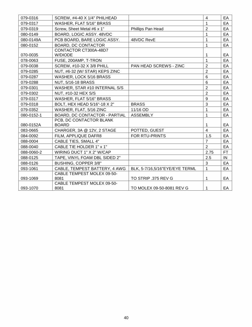
079-0316 SCREW, #4-40 X 1/4" PHILHEAD 4 EA 079-0317 WASHER, FLAT 5/16" BRASS 1 EA 079-0319 Screw, Sheet Metal #6 x 1" Phillips Pan Head 2 EA 080-0149 BOARD, LOGIC ASSY. 48VDC 1 EA 080-0149A PCB BOARD, BARE LOGIC ASSY. 48VDC RevE 1 EA 080-0152 BOARD, DC CONTACTOR 1 EA
070-0035 CONTACTOR CT300A-48D7 W/DIODE 1 EA
078-0063 FUSE, 200AMP, T-TRON 1 EA 079-0038 SCREW, #10-32 X 3/8 PHILL PAN HEAD SCREWS - ZINC 2 EA 079-0285 NUT, #6-32 (W/ STAR) KEPS ZINC 2 EA 079-0287 WASHER, LOCK 5/16 BRASS 6 EA 079-0288 NUT, 5/16-18 BRASS 6 EA 079-0301 WASHER, STAR #10 INTERNAL S/S 2 EA 079-0302 NUT, #10-32 HEX S/S 2 EA 079-0317 WASHER, FLAT 5/16" BRASS 9 EA 079-0318 BOLT, HEX HEAD 5/16"-18 X 2" BRASS 3 EA 079-0352 WASHER, FLAT, 5/16 ZINC 11/16 OD 1 EA 080-0152-1 BOARD, DC CONTACTOR - PARTIAL ASSEMBLY 1 EA
080-0152A PCB, DC CONTACTOR BLANK BOARD 1 EA
083-0665 CHARGER, 3A @ 12V, 2 STAGE POTTED, GUEST 4 EA 084-0092 FILM, APPLIQUE DAFR8 FOR RTU-PRINTS 1.5 EA 088-0004 CABLE TIES, SMALL 4" 7 EA 088-0040 CABLE TIE HOLDER 1" x 1" 2 EA 088-0060-2 WIRING DUCT 1" X 2" W/CAP 2.75 FT 088-0125 TAPE, VINYL FOAM DBL SIDED 2" 2.5 IN 088-0126 BUSHING, COPPER 3/8" 3 EA 093-1061 CABLE, TEMPEST BATTERY, 4 AWG BLK, 5-7/16,5/16"EYE/EYE TERML 1 EA
093-1069 CABLE TEMPEST MOLEX 09-50-8081 TO STRIP .375 REV G 1 EA
093-1070 CABLE TEMPEST MOLEX 09-50-8081 TO MOLEX 09-50-8081 REV G 1 EA
41
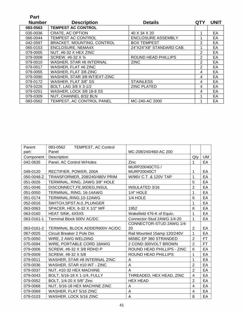
Part Number Description Details QTY UNIT
083-0563 TEMPEST AC CONTROL 035-0036 CRATE, AC OPTION 40 X 34 X 20 1 EA 066-0044 TEMPEST AC CONTROL ENCLOSURE ASSEMBLY 1 EA 042-0597 BRACKET, MOUNTING, CONTROL BOX TEMPEST 2 EA 065-0153 ENCLOSURE, NEMA4X 24”X24”X8” STANDARD CAB. 1 EA 079-0005 NUT, #6-32 X HEX ZINC 2 EA 079-0008 SCREW, #6-32 X ¾ ROUND HEAD PHILLIPS 2 EA 079-0010 WASHER, STAR #6 INTERNAL ZINC 2 EA 079-0017 WASHER, FLAT #6 ZINC 2 EA 079-0055 WASHER, FLAT 3/8 ZINC 4 EA 079-0090 WASHER, STAR 3/8 INT/EXT-ZINC 4 EA 079-0172 WASHER, FLAT 3/8” SS STAINLESS 4 EA 079-0226 BOLT, LAG 3/8 X 3-1/2 ZINC PLATED 4 EA 079-0251 WASHER, LOCK 3/8 18-8 SS 4 EA 079-0309 NUT, CHANNEL 8/32 BLN 1 EA 083-0562 TEMPEST, AC CONTROL PANEL MC-240-AC 2000 1 EA
Parent part:
083-0562 TEMPEST, AC Control Panel MC-208/240/460-AC 200
Component Description Qty UM 042-0635 Panel, AC Control W/Holes Zinc 1 EA
049-0120 RECTIFIER, POWER, 200A MURP20040CTG / MURP20040CT 1 EA
050-0048-2 TRANSFORMER, 208/240/480V PRIM W/96V C.T. & 120V TAP 1 EA 051-0026 TERMINAL, RING, 2AWG 3/8" HOLE 5 EA 051-0046 DISCONNECT,FE,90DEG,INSUL INSULATED 3/16 2 EA 051-0050 TERMINAL, RING, 16-14AWG 1/4" HOLE 1 EA 051-0174 TERMINAL,RING,10-12AWG 1/4 HOLE 6 EA 052-0016 SWITCH,SPST,N.0.,PLUNGER 1 EA 063-0063 SPACER, HEX, 6-32 X 1/2" M/F 1952 6 EA 063-0160 HEAT SINK, 6X5X5 Wakefield 476-K of Equiv. 1 EA 063-0161-1 Terminal Block 600V AC/DC Connector-Stud 2AWG 1/4-20 1 EA
063-0161-2 TERMINAL BLOCK ADDER600V AC/DC CONNECTOR-STUD 2AWG 1/4-20 2 EA
067-0025 Circuit Breaker 2 Pole Din Rail Mounted 15amp 120/240V 1 EA 075-0050 WIRE, 2 AWG WELDING 665BC EP 360 STRANDED 2 FT 075-0094 WIRE, PORTABLE CORD 18AWG 2 COND 300VOLT BROWN 2 FT 079-0006 SCREW, #6-32 X 3/8 RDHD P ROUND HEAD PHILLIPS - ZINC 6 EA 079-0009 SCREW, #8-32 X 5/8 ROUND HEAD PHILLIPS 1 EA 079-0011 WASHER, STAR #8 INTERNAL ZINC A 1 EA 079-0036 WASHER, STAR #10 INT - ZINC A 2 EA 079-0037 NUT, #10-32 HEX MACHINE A 2 EA 079-0043 BOLT, 5/16-18 X 1-1/4, FULLY THREADED, HEX HEAD, ZINC 4 EA 079-0052 BOLT, 1/4-20 X 5/8" Zinc HEX HEAD 2 EA 079-0068 NUT, 5/16-18 HEX MACHINE ZINC A 4 EA 079-0069 WASHER, FLAT 5/16 ZINC A 4 EA 079-0103 WASHER, LOCK 5/16 ZINC A 8 EA
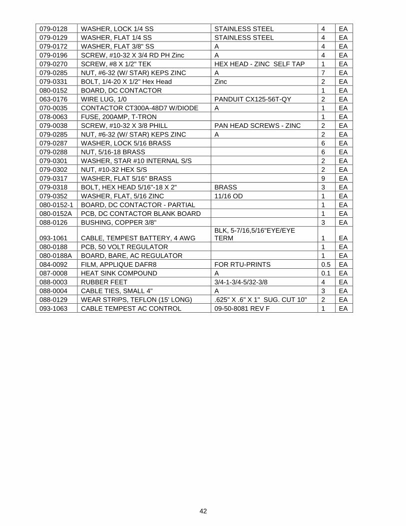
42
079-0128 WASHER, LOCK 1/4 SS STAINLESS STEEL 4 EA 079-0129 WASHER, FLAT 1/4 SS STAINLESS STEEL 4 EA 079-0172 WASHER, FLAT 3/8" SS A 4 EA 079-0196 SCREW, #10-32 X 3/4 RD PH Zinc A 4 EA 079-0270 SCREW, #8 X 1/2" TEK HEX HEAD - ZINC SELF TAP 1 EA 079-0285 NUT, #6-32 (W/ STAR) KEPS ZINC A 7 EA 079-0331 BOLT, 1/4-20 X 1/2" Hex Head Zinc 2 EA 080-0152 BOARD, DC CONTACTOR 1 EA 063-0176 WIRE LUG, 1/0 PANDUIT CX125-56T-QY 2 EA 070-0035 CONTACTOR CT300A-48D7 W/DIODE A 1 EA 078-0063 FUSE, 200AMP, T-TRON 1 EA 079-0038 SCREW, #10-32 X 3/8 PHILL PAN HEAD SCREWS - ZINC 2 EA 079-0285 NUT, #6-32 (W/ STAR) KEPS ZINC A 2 EA 079-0287 WASHER, LOCK 5/16 BRASS 6 EA 079-0288 NUT, 5/16-18 BRASS 6 EA 079-0301 WASHER, STAR #10 INTERNAL S/S 2 EA 079-0302 NUT, #10-32 HEX S/S 2 EA 079-0317 WASHER, FLAT 5/16" BRASS 9 EA 079-0318 BOLT, HEX HEAD 5/16"-18 X 2" BRASS 3 EA 079-0352 WASHER, FLAT, 5/16 ZINC 11/16 OD 1 EA 080-0152-1 BOARD, DC CONTACTOR - PARTIAL 1 EA 080-0152A PCB, DC CONTACTOR BLANK BOARD 1 EA 088-0126 BUSHING, COPPER 3/8" 3 EA
093-1061 CABLE, TEMPEST BATTERY, 4 AWG BLK, 5-7/16,5/16"EYE/EYE TERM 1 EA
080-0188 PCB, 50 VOLT REGULATOR 1 EA 080-0188A BOARD, BARE, AC REGULATOR 1 EA 084-0092 FILM, APPLIQUE DAFR8 FOR RTU-PRINTS 0.5 EA 087-0008 HEAT SINK COMPOUND A 0.1 EA 088-0003 RUBBER FEET 3/4-1-3/4-5/32-3/8 4 EA 088-0004 CABLE TIES, SMALL 4" A 3 EA 088-0129 WEAR STRIPS, TEFLON (15' LONG) .625" X .6" X 1" SUG. CUT 10" 2 EA 093-1063 CABLE TEMPEST AC CONTROL 09-50-8081 REV F 1 EA