Embed Size (px)
Citation preview

306 Introduction to Basic Manufacturing Processes and Workshop Technology
306
WELDING
17.1 INTRODUCTION
Welding is a process for joining two similar or dissimilar metals by fusion. It joins different
metals/alloys, with or without the application of pressure and with or without the use of filler
metal. The fusion of metal takes place by means of heat. The heat may be generated either
from combustion of gases, electric arc, electric resistance or by chemical reaction. During
some type of welding processes, pressure may also be employed, but this is not an essential
requirement for all welding processes. Welding provides a permanent joint but it normally
affects the metallurgy of the components. It is therefore usually accompanied by post weld
heat treatment for most of the critical components. The welding is widely used as a fabrication
and repairing process in industries. Some of the typical applications of welding include the
fabrication of ships, pressure vessels, automobile bodies, off-shore platform, bridges, welded
pipes, sealing of nuclear fuel and explosives, etc.
Most of the metals and alloys can be welded by one type of welding process or the other.
However, some are easier to weld than others. To compare this ease in welding term
‘weldability’ is often used. The weldability may be defined as property of a metal which
indicates the ease with which it can be welded with other similar or dissimilar metals.
Weldability of a material depends upon various factors like the metallurgical changes that
occur due to welding, changes in hardness in and around the weld, gas evolution and absorption,
extent of oxidation, and the effect on cracking tendency of the joint. Plain low carbon steel
(C-0.12%) has the best weldability amongst metals. Generally it is seen that the materials
with high castability usually have low weldability.
17.2 TERMINOLOGICAL ELEMENTS OF WELDING PROCESS
The terminological elements of welding process used with common welding joints such as
base metal, fusion zone, weld face, root face, root opening toe and root are depicted in Fig.
17.1
17.2.1 Edge preparations
For welding the edges of joining surfaces of metals are prepared first. Different edge preparations
may be used for welding butt joints, which are given in Fig 17.2.
17CHAPTER

Welding 307
W eld faceFusion zone
Base m etal
Root face
Root open ing
(a) Bu tt weld
Toe
W eld face
Toe
Root
(b ) Fillet weld
Fusion zone
Fig. 17.1 Terminological elements of welding process
Straigh t
S ing le - V
Doub le - V
S ing le bevel
Doub le bevel
S ing le - U
Doub le - U
S ing le - J
Doub le - J
Fig. 17.2 Butt welding joints edge preparations
17.2.2 Welding joints
Some common welding joints are shown in Fig. 17.3. Welding joints are of generally of two
major kinds namely lap joint and butt joint. The main types are described as under.
17.2.2.1 Lap weld joint
Single-Lap Joint
This joint, made by overlapping the edges of the plate, is not recommended for most
work. The single lap has very little resistance to bending. It can be used satisfactorily for
joining two cylinders that fit inside one another.
Double-Lap Joint
This is stronger than the single-lap joint but has the disadvantage that it requires twice
as much welding.
Tee Fillet Weld
This type of joint, although widely used, should not be employed if an alternative design
is possible.

308 Introduction to Basic Manufacturing Processes and Workshop Technology
Plain bu tt
S ing le - V bu tt Doub le - V butt S ing le - U bu tt
Doub le - U butt
S ing le lap Doub le lap
Joggled P lain T
Sing le V-T Doub le V-T S ing le U -T
Doub le U -T Flush cornerHa lf co rner
Fu ll corner P lain edge V edge
U edgePlug
Fig. 17.3 Types of welding joints
17.2.2.2 Butt weld joint
Single-Vee Butt Weld
It is used for plates up to 15.8 mm thick. The angle of the vee depends upon the
technique being used, the plates being spaced approximately 3.2 mm.
Double-Vee Butt Weld
It is used for plates over 13 mm thick when the welding can be performed on both sides
of the plate. The top vee angle is either 60° or 80°, while the bottom angle is 80°, depending
on the technique being used.
17.2.3 Welding Positions
As shown in Fig. 17.4, there are four types of welding positions, which are given as:
1. Flat or down hand position

Welding 309
2. Horizontal position
3. Vertical position
4. Overhead position
Flat Vertica l Horizon ta l O ver head
Fig. 17.4 Kinds of welding positions
17.2.3.1 Flat or Downhand Welding Position
The flat position or down hand position is one in which the welding is performed from
the upper side of the joint and the face of the weld is approximately horizontal. This is the
simplest and the most convenient position for welding. Using this technique, excellent welded
joints at a fast speed with minimum risk of fatigue to the welders can be obtained.
17.2.3.2 Horizontal Welding Position
In horizontal position, the plane of the workpiece is vertical and the deposited weld head
is horizontal. The metal deposition rate in horizontal welding is next to that achieved in flat
or downhand welding position. This position of welding is most commonly used in welding
vessels and reservoirs.
17.2.3.3 Veritical Welding Position
In vertical position, the plane of the workpiece is vertical and the weld is deposited upon a
vertical surface. It is difficult to produce satisfactory welds in this position due to the effect
of the force of gravity on the molten metal. The welder must constantly control the metal
so that it does not run or drop from the weld. Vertical welding may be of two types viz.,
vertical-up and vertical-down. Vertical-up welding is preferred when strength is the major
consideration. The vertical-down welding is used for a sealing operation and for welding sheet
metal.
17.2.3.4 Overhead Welding Position
The overhead position is probably even more difficult to weld than the vertical position.
Here the pull of gravity against the molten metal is much greater. The force of the flame
against the weld serves to counteract the pull of gravity. In overhead position, the plane of
the workpiece is horizontal. But the welding is carried out from the underside. The electrode
is held with its welding end upward. It is a good practice to use very short arc and basic coated
electrodes for overhead welding.
17.3 ADVANTAGES AND DISADVANTAGES OF WELDING
Advantages
1. Welding is more economical and is much faster process as compared to other
processes (riveting, bolting, casting etc.)
310 Introduction to Basic Manufacturing Processes and Workshop Technology
2. Welding, if properly controlled results permanent joints having strength equal or
sometimes more than base metal.
3. Large number of metals and alloys both similar and dissimilar can be joined by
welding.
4. General welding equipment is not very costly.
5. Portable welding equipments can be easily made available.
6. Welding permits considerable freedom in design.
7. Welding can join welding jobs through spots, as continuous pressure tight seams,
end-to-end and in a number of other configurations.
8. Welding can also be mechanized.
Disadvantages
1. It results in residual stresses and distortion of the workpieces.
2. Welded joint needs stress relieving and heat treatment.
3. Welding gives out harmful radiations (light), fumes and spatter.
4. Jigs, and fixtures may also be needed to hold and position the parts to be welded
5. Edges preparation of the welding jobs are required before welding
6. Skilled welder is required for production of good welding
7. Heat during welding produces metallurgical changes as the structure of the welded
joint is not same as that of the parent metal.
17.4 CLASSIFICATION OF WELDING AND ALLIED PROCESSES
There are different welding, brazing and soldering methods are being used in industries today.
There are various ways of classifying the welding and allied processes. For example, they may
be classified on the basis of source of heat, i.e., blacksmith fire, flame, arc, etc. and the type
of interaction i.e., liquid / liquid (fusion welding) or solid/solid (solid state welding). Welding
processes may also be classified in two categories namely plastic (forge) and fusion. However,
the general classification of welding and allied processes is given as under
(A) Welding Processes
1. Oxy-Fuel Gas Welding Processes
1 Air-acetylene welding
2 Oxy-acetylene welding
3 Oxy-hydrogen welding
4 Pressure gas welding
2. Arc Welding Processes
1. Carbon Arc Welding
2. Shielded Metal Arc Welding
3. Submerged Arc Welding
4. Gas Tungsten Arc Welding

Welding 311
5. Gas Metal Arc Welding
6. Plasma Arc Welding
7. Atomic Hydrogen Welding
8. Electro-slag Welding
9. Stud Arc Welding
10. Electro-gas Welding
3. Resistance Welding
1. Spot Welding
2. Seam Welding
3. Projection Welding
4. Resistance Butt Welding
5. Flash Butt Welding
6. Percussion Welding
7. High Frequency Resistance Welding
8. High Frequency Induction Welding
4. Solid-State Welding Processes
1. Forge Welding
2. Cold Pressure Welding
3. Friction Welding
4. Explosive Welding
5. Diffusion Welding
6. Cold Pressure Welding
7. Thermo-compression Welding
5. Thermit Welding Processes
1. Thermit Welding
2. Pressure Thermit Welding
6. Radiant Energy Welding Processes
1. Laser Welding
2. Electron Beam Welding
(B) Allied Processes
1. Metal Joining or Metal Depositing Processes
1. Soldering
2. Brazing
3. Braze Welding
4. Adhesive Bonding

312 Introduction to Basic Manufacturing Processes and Workshop Technology
5. Metal Spraying
6. Surfacing
2. Thermal Cuting Processes
1. Gas Cutting
2. Arc Cutting
Some of the important and widely used welding processes are discussed in the rest of this
chapter.
17.5 GAS WELDING PROCESSES
A fusion welding process which joins metals, using the heat of combustion of an oxygen /air
and fuel gas (i.e. acetylene, hydrogen propane or butane) mixture is usually referred as ‘gas
welding’. The intense heat (flame) thus produced melts and fuses together the edges of the
parts to be welded, generally with the addition of a filler metal. Operation of gas welding is
shown in Fig. 17.5. The fuel gas generally employed is acetylene; however gases other than
acetylene can also be used though with lower flame temperature. Oxy-acetylene flame is the
most versatile and hottest of all the flames produced by the combination of oxygen and other
fuel gases. Other gases such as Hydrogen, Propane, Butane, Natural gas etc., may be used
for some welding and brazing applications.
W eldingto rch tip
D irection of we ld ing
M olten we ld m etal
Base m etal
So lidified we ld m eta l
W elding rod
Inner cone
Fig. 17.5 Gas welding operation
17.5.1 Oxy-Acetylent Welding
In this process, acetylene is mixed with oxygen in correct proportions in the welding torch
and ignited. The flame resulting at the tip of the torch is sufficiently hot to melt and join the
parent metal. The oxy-acetylene flame reaches a temperature of about 3300°C and thus can
melt most of the ferrous and non-ferrous metals in common use. A filler metal rod or welding
rod is generally added to the molten metal pool to build up the seam slightly for greater
strength.
17.5.1.1 Types of Welding Flames
In oxy-acetylene welding, flame is the most important means to control the welding joint
and the welding process. The correct type of flame is essential for the production of satisfactory
welds. The flame must be of the proper size, shape and condition in order to operate with
maximum efficiency. There are three basic types of oxy-acetylene flames.
1. Neutral welding flame (Acetylene and oxygen in equal proportions).

Welding 313
2. Carburizing welding flame or reducing (excess of acetylene).
3. Oxidizing welding flame (excess of oxygen).
The gas welding flames are shown in Fig 17.6.
Torch tip Inner cone O uter enve lope
Neutra l flam e
Feather
Carburis ing flam e(Excessive acety lene )
O xid iz ing flam e(Excessive oxygen)
Fig. 17.6 Gas welding flames
Neutral Welding Flame
A neutral flame results when approximately equal volumes of oxygen and acetylene are mixed
in the welding torch and burnt at the torch tip. The temperature of the neutral flame is of
the order of about 5900°F (3260°C). It has a clear, well defined inner cone, indicating that the
combustion is complete. The inner cone is light blue in color. It is surrounded by an outer
flame envelope, produced by the combination of oxygen in the air and superheated carbon
monoxide and hydrogen gases from the inner cone. This envelope is Usually a much darker
blue than the inner cone. A neutral flame is named so because it affects no chemical change
on the molten metal and, therefore will not oxidize or carburize the metal. The neutral flame
is commonly used for the welding of mild steel, stainless steel, cast Iron, copper, and aluminium.
Carburising or Reducing Welding Flame
The carburizing or reducing flame has excess of acetylene and can be recognized by
acetylene feather, which exists between the inner cone and the outer envelope. The outer
flame envelope is longer than that of the neutral flame and is usually much brighter in color.
With iron and steel, carburizing flame produces very hard, brittle substance known as iron
carbide. A reducing flame may be distinguished from carburizing flame by the fact that a
carburizing flame contains more acetylene than a reducing flame. A reducing flame has an
approximate temperature of 3038°C. A carburizing-flame is used in the welding of lead and for
carburizing (surface hardening) purpose. A reducing flame, on the other hand, does not
carburize the metal; rather it ensures the absence of the oxidizing condition. It is used for
welding with low alloy steel rods and for welding those metals, (e.g., non-ferrous) that do not
tend to absorb carbon. This flame is very well used for welding high carbon steel.
Oxidising Welding flame
The oxidizing flame has an excess of oxygen over the acetylene. An oxidizing flame can
be recognized by the small cone, which is shorter, much bluer in color and more pointed than
that of the neutral flame. The outer flame envelope is much shorter and tends to fan out at

314 Introduction to Basic Manufacturing Processes and Workshop Technology
the end. Such a flame makes a loud roaring sound. It is the hottest flame (temperature as
high as 6300°F) produced by any oxy-fuel gas source. But the excess oxygen especially at high
temperatures tends to combine with many metals to form hard, brittle, low strength oxides.
Moreover, an excess of oxygen causes the weld bead and the surrounding area to have a
scummy or dirty appearance. For these reasons, an oxidizing flame is of limited use in
welding. It is not used in the welding of steel. A slightly oxidizing flame is helpful when
welding (i) Copper-base metals (ii) Zinc-base metals and (iii) A few types of ferrous metals such
as manganese steel and cast iron. The oxidizing atmosphere in these cases, create a base-
metal oxide that protects the base metal.
17.5.1.2 Gas Welding Equipments
An arrangement of oxy acetylene welding set up is shown in Fig.17.7. The basic tools and
equipments used for oxy-acetylene welding are following:
19
20
21
22
10
8
12 13 1716
1815
14
11654
2
3 7
9
Ox
yg
en
Ac
et y
len
e
1. Acetylene hose2. Ad justing screw3. Acetylene regulator4 . Regu la to r ou tlet pressure gauge5. Cylinder pressure gauge6. Valve w rench7. Ace tylene cy linder valve8 . Cylinder cap
9. Fusib le plugs10. O xygen hose11. O xygen regu la to r12. Regulator ou tle t p ressure gauge13. Cylinder p ressure gauge14. Cylinder cap15. O xygen cy linder valve16. O xygen cy linder valve
17. Hand wheel 18. Bursting d isc19. Acety lene va lve20. O xygen va lve21. Weld ing to rch22. Torch tip23. Flam e
23
Fig. 17.7 Oxy acetylene welding set up
Acetylene and oxygen gas is stored in compressed gas cylinders. These gas cylinders
differ widely in capacity, design and colour code. However, in most of the countries, the
standard size of these cylinders is 6 to 7 m3 and is painted black for oxygen and maroon for
acetylene. An acetylene cylinder is filled with some absorptive material, which is saturated
with a chemical solvent acetone. Acetone has the ability to absorb a large volume of acetylene
and release it as the pressure falls. If large quantities of acetylene gas are being consumed,
it is much cheaper to generate the gas at the place of use with the help of acetylene gas
generators. Acetylene gas is generated by carbide-to-water method.
Oxygen gas cylinders are usually equipped with about 40 litres of oxygen at a pressure
of about 154 Kgf/cm2 at 21°C. To provide against dangerously excessive pressure, such as

Welding 315
could occur if the cylinders were exposed to fire, every valve has a safety device to release
the oxygen before there is any danger of rupturing the cylinders. Fragile discs and fusible
plugs are usually provided in the cylinders valves in case it is subjected to danger.
Gas pressure regulators
Gas pressure regulators are employed for regulating the supply of acetylene and oxygen
gas from cylinders. A pressure regulator is connected between the cylinder and hose leading
to welding torch. The cylinder and hose connections have left-handed threads on the acetylene
regulator while these are right handed on the oxygen regulator. A pressure regulator is fitted
with two pressure gauges, one for indication of the gas pressure in the cylinder and the other
for indication of the reduced pressure at which the gas is going out.
Welding torch
Fig 17.8 shows the construction of the welding torch. It is a tool for mixing oxygen and
acetylene in correct proportion and burning the mixture at the end of a tip. Gas flow to the
torch is controlled with the help of two needle valves in the handle of the torch. There are
two basic types of gas welding torches:
(1) Positive pressure (also known as medium or equal pressure), and
(2) Low pressure or injector type
The positive pressure type welding torch is the more common of the two types of oxy-
acetylene torches.
Flam eM ix ing cham ber
O xygen
Acetylene
Need le valve con tro l
C H
hose 2 2
O
hose2
Fig. 17.8 Welding torch
Torch tips
It is the portion of the welding apparatus through which the gases pass just prior to their
ignition and burning. A great variety of interchangeable welding tips differing in size, shape
and construction are available commercially. The tip sizes are identified by the diameter of
the opening. The diameter of the tip opening used for welding depends upon the type of metal
to be welded.
Hose pipes
The hose pipes are used for the supply of gases from the pressure regulators. The most
common method of hose pipe fitting both oxygen and acetylene gas is the reinforced rubber
hose pipe. Green is the standard color for oxygen hose, red for acetylene, and black hose for
other industrially available welding gases.
316 Introduction to Basic Manufacturing Processes and Workshop Technology
Goggles
These are fitted with colored lenses and are used to protect the eyes from harmful heat
and ultraviolet and infrared rays.
Gloves
These are required to protect the hands from any injury due to the heat of welding
process.
Spark-lighter
It is used for frequent igniting the welding torch.
Filler rods
Gas welding can be done with or without using filler rod. When welding with the filler
rod, it should be held at approximately 900 to the welding tip. Filler rods have the same or
nearly the same chemical composition as the base metal. Metallurgical properties of the weld
deposit can be controlled by the optimum choice of filler rod. Most of the filler rods for gas
welding also contain deoxidizers to control the oxygen content of weld pool.
Fluxes
Fluxes are used in gas welding to remove the oxide film and to maintain a clean surface.
These are usually employed for gas welding of aluminium, stainless steel, cast iron, brass and
silicon bronze. They are available in the market in the form of dry powder, paste, or thick
solutions.
17.5.2 Safety Recommendations for Gas Welding
Welding and cutting of metals involve the application of intense heat to the objects being
welded or cut. This intense heat in welding is obtained from the use of inflammable gases,
(e.g. acetylene, hydrogen, etc.) or electricity. The intense welding heat and the sources
employed to produce it can be potentially hazardous. Therefore, to protect persons from
injury and to protect building and equipment against fire, etc., a set of recommendations
concerning safety and health measures for the welders and those concerned with the safety
of the equipments etc., have been published by BIS and many other similar but International
organizations. By keeping in mind these recommendations or precautions, the risks associated
with welding can be largely reduced. Therefore, it is suggested that the beginner in the field
of gas welding must go through and become familiar with these general safety
recommendations, which are given below.
1. Never hang a torch with its hose on regulators or cylinder valves.
2. During working, if the welding tip becomes overheated it may be cooled by plunging
the torch into water; close the acetylene valve but leave a little oxygen flowing.
3. Always use the correct pressure regulators for a gas. Acetylene pressure regulator
should never be used with any other gas.
4. Do not move the cylinder by holding the pressure regulator and also handle pressure
regulators carefully.
5. Use pressure regulator only at pressures for which it is intended.
6. Open cylinder valves slowly to avoid straining the mechanism of pressure regulator.
7. Never use oil, grease or lubricant of any kind on regulator connections.
Welding 317
8. For repairs, calibrations and adjustments purposes, the pressure regulators should
be sent to the supplier.
9. Do cracking before connecting pressure regulator to the gas cylinder.
10. Inspect union nuts and connections on regulators before use to detect faulty seats
which may cause leakage of gas when the regulators are attached to the cylinder
valves.
11. Hose connections shall be well fittings and clamped properly otherwise securely
fastened to these connections in such a manner as to withstand without leakage a
pressure twice as great as the maximum delivery pressure of the pressure regulators
provided on the system.
12. Protect the hose from flying sparks, hot slag, hot workpiece and open flame. If dirt
goes into hose, blow through (with oxygen, not acetylene) before coupling to torch
or regulator.
13. Store hose on a reel (an automobile wheel) when not in use.
14. Never allow the hose to come into contact with oil or grease; these deteriorate the
rubber and constitute a hazard with oxygen.
15. Use the correct color hose for oxygen (green/black) and acetylene (red) and never
use oxygen hose for acetylene or vice versa.
16. Always protect hose from being trampled on or run over. Avoid tangle and kinks.
Never leave the hose so that it can be tripped over.
Hazards of fumes, gases and dusts can be minimized by (i) improving general ventilation
of the place where welding is carried out (ii) using local exhaust units, and (iii) wearing
individual respiratory protective equipment.
17.6 ARC WELDING PROCESSES
The process, in which an electric arc between an electrode and a workpiece or between two
electrodes is utilized to weld base metals, is called an arc welding process. The basic principle
of arc welding is shown in Fig 17.9(a). However the basic elements involved in arc welding
process are shown in Fig. 17.9(b). Most of these processes use some shielding gas while others
employ coatings or fluxes to prevent the weld pool from the surrounding atmosphere. The
various arc welding processes are:
1. Carbon Arc Welding
2. Shielded Metal Arc Welding
3. Flux Cored Arc Welding
4. Gas Tungsten Arc Welding
5. Gas Metal Arc Welding
6. Plasma Arc Welding
7. Atomic Hydrogen Welding
8. Electroslag Welding
9. Stud Arc Welding
10. Electrogas Welding

318 Introduction to Basic Manufacturing Processes and Workshop Technology
Electrode
W eldbead
W ork
E lectrode Ho lder
Cable
AC
W eldingm ach ineEarth ing
Fig. 17.9(a) Principle of arc welding
1
2
5
3
6
11
6
8
10
9
1716
13 14 15
12
(1) Sw itch box.(2 ) Secondary term ina ls .(3 ) W elding m ach ine.(4 ) Curren t reading sca le .(5 ) Curren t regulating hand wheel.(6 ) Lea ther apron .
(7 ) Asbestos hand gloves.(8 ) Pro tective glasses strap .(9 ) E lectrode holder.(10) Hand sh ie ld .(11) Channe l for cable pro tection.(12) Weld ing cable.
(13) Chipp ing hamm er.(14) W ire b rush .(15) Earth clam p.(16) Weld ing tab le (m etallic).(17) Job.
Fig. 17.9(b) Arc welding process setup
17.6.1 Arc Welding Equipment
Arc welding equipment, setup and related tools and accessories are shown in Fig. 17.9.
However some common tools of arc welding are shown separately through Fig. 17.10-17.17.
Few of the important components of arc welding setup are described as under.
1. Arc welding power source
Both direct current (DC) and alternating current (AC) are used for electric arc welding,
each having its particular applications. DC welding supply is usually obtained from generators
driven by electric motor or if no electricity is available by internal combustion engines. For
AC welding supply, transformers are predominantly used for almost all arc welding where

Welding 319
mains electricity supply is available. They have to step down the usual supply voltage (200-
400 volts) to the normal open circuit welding voltage (50-90 volts). The following factors
influence the selection of a power source:
1. Type of electrodes to be used and metals to be welded
2. Available power source (AC or DC)
3. Required output
4. Duty cycle
5. Efficiency
6. Initial costs and running costs
7. Available floor space
8. Versatility of equipment
Fig. 17.10 Electrode holder Fig. 17.11 Earth clamp
Poin t
Hand le
Ch isel
Fig. 17.12 Hand screen Fig. 17.13 Chipping and hammer
Hand le
Fig. 17.14 Wire brush Fig. 17.15 C-clamp

320 Introduction to Basic Manufacturing Processes and Workshop Technology
Scriber
Fig. 17.16 V-block Fig. 17.17 Scriber
2. Welding cables
Welding cables are required for conduction of current from the power source through
the electrode holder, the arc, the workpiece and back to the welding power source. These are
insulated copper or aluminium cables.
3. Electrode holder
Electrode holder is used for holding the electrode mannually and conducting current to
it. These are usually matched to the size of the lead, which in turn matched to the amperage
output of the arc welder. Electrode holders are available in sizes that range from 150 to 500
Amps.
4. Welding Electrodes
An electrode is a piece of wire or a rod of a metal or alloy, with or without coatings. An
arc is set up between electrode and workpiece. Welding electrodes are classified into following
types-
(1) Consumable Electrodes
(a) Bare Electrodes
(b) Coated Electrodes
(2) Non-consumable Electrodes
(a) Carbon or Graphite Electrodes
(b) Tungsten Electrodes
Consumable electrode is made of different metals and their alloys. The end of this
electrode starts melting when arc is struck between the electrode and workpiece. Thus
consumable electrode itself acts as a filler metal. Bare electrodes consist of a metal or alloy
wire without any flux coating on them. Coated electrodes have flux coating which starts
melting as soon as an electric arc is struck. This coating on melting performs many functions
like prevention of joint from atmospheric contamination, arc stabilizers etc.
Non-consumable electrodes are made up of high melting point materials like carbon,
pure tungsten or alloy tungsten etc. These electrodes do not melt away during welding. But
practically, the electrode length goes on decreasing with the passage of time, because of
oxidation and vaporization of the electrode material during welding. The materials of non-
consumable electrodes are usually copper coated carbon or graphite, pure tungsten, thoriated
or zirconiated tungsten.
5. Hand Screen
Hand screen (Fig. 17.12) used for protection of eyes and supervision of weld bead.
Welding 321
6. Chipping hammer
Chipping Hammer (Fig. 17.13) is used to remove the slag by striking.
7. Wire brush
Wire brush (Fi. 17.14) is used to clean the surface to be weld.
8. Protective clothing
Operator wears the protective clothing such as apron to keep away the exposure of direct
heat to the body.
17.6.2 Carbon Arc Welding
In this process, a pure graphite or baked carbon rod is used as a non-consumable electrode
to create an electric arc between it and the workpiece. The electric arc produces heat and
weld can be made with or without the addition of filler material. Carbon arc welding may be
classified as-
(1) Single electrode arc welding, and
(2) Twin carbon electrode arc welding
In single electrode arc welding, an electric arc is struck between a carbon electrode and
the workpiece. Welding may be carried out in air or in an inert atmosphere. Direct current
straight polarity (DCSP) is preferred to restrict electrode disintegration and the amount of
carbon going into the weld metal. This process is mainly used for providing heat source for
brazing, braze welding, soldering and heat treating as well as for repairing iron and steel
castings. It is also used for welding of galvanized steel and copper.
In twin carbon arc welding the arc struck between two carbon electrodes produces heat
and welds the joint. The arc produced between these two electrodes heats the metal to the
melting temperature and welds the joint after solidification. The power source used is AC
(Alternating Current) to keep the electrodes at the same temperature. Twin-electrode carbon
arc welding can be used for welding in any position. This process is mainly used for joining
copper alloys to each other or to ferrous metal. It can also be used for welding aluminium,
nickel, zinc and lead alloys.
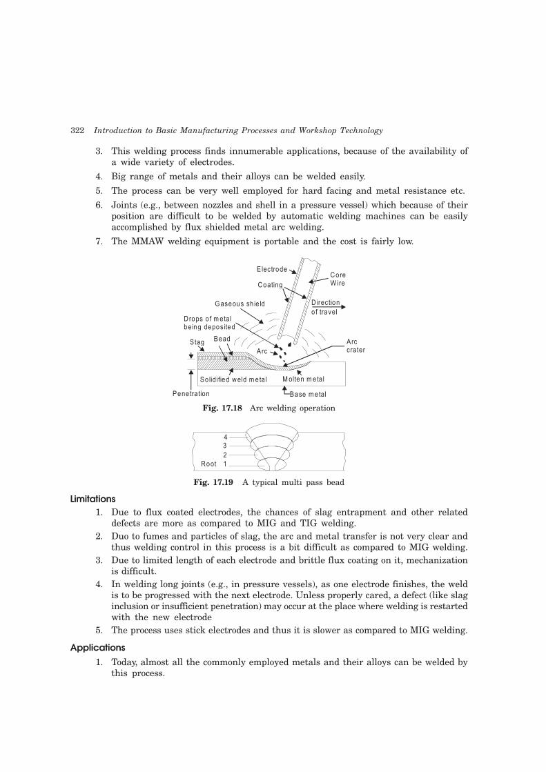
17.6.3 Shielded Metal Arc Welding (SMAW) or Manual Metal Arc Welding (MMAW)
Shielded metal arc welding (SMAW) is a commonly used arc welding process manually carried
by welder. It is an arc welding process in which heat for welding is produced through an
electric arc set up between a flux coated electrode and the workpiece. The flux coating of
electrode decomposes due to arc heat and serves many functions, like weld metal protection,
arc stability etc. Inner core of the electrode supply the filler material for making a weld. The
basic setup of MMAW is depicted in Fig. 17.9 (a), (b) and the configuration of weld zone is
shown in Fig. 17.18. If the parent metal is thick it may be necessary to make two or three
passes for completing the weld. A typical multi pass bead in this case is shown in Fig. 17.19.
Advantages
1. Shielded Metal Arc Welding (SMAW) can be carried out in any position with highest
weld quality.
2. MMAW is the simplest of all the arc welding processes.
322 Introduction to Basic Manufacturing Processes and Workshop Technology
3. This welding process finds innumerable applications, because of the availability of
a wide variety of electrodes.
4. Big range of metals and their alloys can be welded easily.
5. The process can be very well employed for hard facing and metal resistance etc.
6. Joints (e.g., between nozzles and shell in a pressure vessel) which because of their
position are difficult to be welded by automatic welding machines can be easily
accomplished by flux shielded metal arc welding.
7. The MMAW welding equipment is portable and the cost is fairly low.
Electrode
Coating
Core W ire
D irection
o f travelD rops o f m etal being deposited
Stag Bead
Arc
Arc crater
G aseous sh ie ld
So lidified weld m eta l M olten m etal
Penetra tion Base m etal
Fig. 17.18 Arc welding operation
43
2
1Root
Fig. 17.19 A typical multi pass bead
Limitations
1. Due to flux coated electrodes, the chances of slag entrapment and other related
defects are more as compared to MIG and TIG welding.
2. Duo to fumes and particles of slag, the arc and metal transfer is not very clear and
thus welding control in this process is a bit difficult as compared to MIG welding.
3. Due to limited length of each electrode and brittle flux coating on it, mechanization
is difficult.
4. In welding long joints (e.g., in pressure vessels), as one electrode finishes, the weld
is to be progressed with the next electrode. Unless properly cared, a defect (like slag
inclusion or insufficient penetration) may occur at the place where welding is restarted
with the new electrode
5. The process uses stick electrodes and thus it is slower as compared to MIG welding.
Applications
1. Today, almost all the commonly employed metals and their alloys can be welded by
this process.

Welding 323
2. Shielded metal arc welding is used both as a fabrication process and for maintenance
and repair jobs.
3. The process finds applications in
(a) Building and Bridge construction
(b) Automotive and aircraft industry, etc.
(c) Air receiver, tank, boiler and pressure vessel fabrication
(d) Ship building
(e) Pipes and
(f) Penstock joining
17.6.3.1 Functions of Electrode Coating Ingredients
The covering coating on the core wire consists of many materials which perform a
number of functions as listed below:
1. Welding electrodes are used to join various similar and dissimilar metals as plain
carbon steels, cast iron, copper, aluminium, magnesium and their alloys, stainless
steels and other alloy steels.
2. Slag forming ingredients, like silicates of magnesium, aluminium, sodium, potassium,
iron oxide, china clay, mica etc., produce a slag which because of its light weight
forms a layer on the molten metal and protects the same from atmospheric
contamination.
3. Arc stabilizing constituents like calcium carbonate, potassium silicate, titanates,
magnesium silicates, etc.; add to arc stability and ease of striking the same.
4. Gas shielding ingredients, like cellulose, wood, wood flour, starch, calcium carbonate
etc. form a protective gas shield around the electrode end, arc and weld pool
5. Deoxidizing elements like ferro-manganese, and ferro-silicon, refine the molten
metal.
6. It limits spatter, produces a quiet arc and easily removable slag.
7. Alloying elements like ferro alloys of manganese, molybdenum etc., may be added
to impart suitable properties and strength to the weld metal and to make good the
loss of some of the elements, which vaporize while welding.
8. Iron powder in the coating improves arc behavior, bead appearance helps increase
metal deposition rate and arc travel speed.
9. The covering improves penetration and surface finish.
10. Core wire melts faster than the covering, thus forming a sleeve of the coating which
constricts and produces an arc with high concentrated heat.
11. Coating saves the welder from the radiations otherwise emitted from a bare electrode
while the current flows through it during welding.
12. Proper coating ingredients produce weld metals resistant to hot and cold cracking.
Suitable coating will improve metal deposition rates.
17.6.4 Submerged Arc Welding
Schematic submerged arc welding process is shown in Fig. 17.20. In this welding process, a
consumable bare electrode is used in combination with a flux feeder tube. The arc, end of the

324 Introduction to Basic Manufacturing Processes and Workshop Technology
bare electrode and molten pool remain completely submerged under blanket of granular flux.
The feed of electrode and tube is automatic and the welding is homogenous in structure. No
pressure is applied for welding purposes. This process is used for welding low carbon steel,
bronze, nickel and other non-ferrous materials.
Solidified flux
To g round
Finished we ld surface
Base m aterial W eld materia l
G ranu la ted we ld ing flux
W elding flux feed tube
W eld direction
W eld backingif requ ired
To power supp ly
W eldinge lectrode
Fig. 17.20 Schematic submerged arc welding process
17.6.5 Gas Tungusten Arc Welding (GTAW) or Tungusten Inert Gas Welding (TIG)
In this process a non-consumable tungsten electrode is used with an envelope of inert shielding
gas around it. The shielding gas protects the tungsten electrode and the molten metal weld
pool from the atmospheric contamination. The shielding gases generally used are argon,
helium or their mixtures. Typical tungsten inert gas welding setup is shown in Fig. 17.21.
Tungsten e lectrode
G as passages
Electrode holder
Insu la tingsheath
W eldingpower sourceSh ie ld ing gas
W ork
Regu la tor
Inert gas
supply
Fig. 17.21 Tungsten inert gas welding setup
Electrode materials
The electrode material may be tungsten, or tungsten alloy (thoriated tungsten or
zirconiated tungsten). Alloy-tungsten electrodes possess higher current carrying capacity,
produce a steadier arc as compared to pure tungsten electrodes and high resistance to
contamination.

Welding 325
Electric power source
Both AC and DC power source can be used for TIG welding. DC is preferred for welding
of copper, copper alloys, nickel and stainless steel whereas DC reverse polarity (DCRP) or AC
is used for welding aluminium, magnesium or their alloys. DCRP removes oxide film on
magnesium and aluminium.
Inert gases
The following inert gases are generally used in TIG welding:
1. Argon
2. Helium
3. Argon-helium mixtures
4. Argon-hydrogen mixtures
Tig Nozzle
The nozzle or shield size (the diameter of the opening of the shroud around the electrode)
to be chosen depends on the shape of the groove to be welded as well as the required gas
flow rate. The gas flow rate depends on the position of the weld as well as its size. Too high
a gas consumption would give rise to turbulence of the weld metal pool and consequently
porous welds. Because of the use of shielding gases, no fluxes are required to be used in inert
gas shielded arc welding. However for thicker sections, it may be desirable to protect the root
side of the joint by providing a flux. The process is generally used for welding aluminium,
magnesium and stainless steel.
17.6.6 Gas Metal ARC Welding (GMAW) or Metal Inert Gas Welding (MIG)
Metal inert gas arc welding (MIG) or more appropriately called as gas metal arc welding
(GMAW) utilizes a consumable electrode and hence, the term metal appears in the title.
There are other gas shielded arc welding processes utilizing the consumable electrodes,
such as flux cored arc welding (FCAW) all of which can be termed under MIG. Though gas
tungsten arc welding (GTAW) can be used to weld all types of metals, it is more suitable
for thin sheets. When thicker sheets are to be welded, the filler metal requirement makes
GTAW difficult to use. In this situation, the GMAW comes handy. The typical setup for
GMAW or MIG welding process is shown in Fig. 17.22. The consumable electrode is in the
form of a wire reel which is fed at a constant rate, through the feed rollers. The welding
torch is connected to the gas supply cylinder which provides the necessary inert gas. The
electrode and the work-piece are connected to the welding power supply. The power supplies
are always of the constant voltage type only. The current from the welding machine is
changed by the rate of feeding of the electrode wire. Normally DC arc welding machines
are used for GMAW with electrode positive (DCRP). The DCRP increases the metal deposition
rate and also provides for a stable arc and smooth electrode metal transfer. With DCSP, the
arc becomes highly unstable and also results in a large spatter. But special electrodes
having calcium and titanium oxide mixtures as coatings are found to be good for welding
steel with DCSP. In the GMAW process, the filler metal is transferred from the electrode
to the joint. Depending on the current and voltage used for a given electrode, the metal
transfer is done in different ways.

326 Introduction to Basic Manufacturing Processes and Workshop Technology
C on tro l sys tem F eed c on tro l
G as ou t
G un con trol
W ire spoo l
G as in
R egu la to r
H and he ld gun
C ab le(pow er, gas , c oolent)
w o rk lead C on tacto r con tro l
110V supp ly
Pow er sou rce
S h ield inggas
sou rce
w ire feed d rive m o tor
Fig. 17.22 Gas metal arc welding (GMAW) set up
17.6.7 Safety Recommendations for ARC Welding
The beginner in the field of arc welding must go through and become familiar with these
general safety recommendations which are given as under.
1. The body or the frame of the welding machine shall be efficiently earthed. Pipe lines
containing gases or inflammable liquids or conduits carrying electrical conductors
shall not be used for a ground return circuit All earth connections shall be
mechanically strong and electrically adequate for the required current.
2. Welding arc in addition to being very is a source of infra-red and ultra-violet light
also; consequently the operator must use either helmet or a hand-shield fitted with
a special filter glass to protect eyes
3. Excess ultra-violet light can cause an effect similar to sunburn on the skin of the welder
4. The welder’s body and clothing are protected from radiation and burns caused by
sparks and flying globules of molten metal with the help of the following:
5. Gloves protect the hands of a welder.
6. Leather or asbestos apron is very useful to protect welder’s clothes and his trunk
and thighs while seated he is doing welding.
7. For overhead welding, some form of protection for the head is required
8. Leather skull cap or peaked cap will do the needful.
9. Leather jackets and 1ather leggings are also available as clothes for body protection.
10. Welding equipment shall be inspected periodically and maintained in safe working
order at all times.
11. Arc welding machines should be of suitable quality.
12. All parts of welding set shall be suitably enclosed and protected to meet the usual
service conditions.
Welding 327
13. Welders and workers need to be protected from welding rays, f1ying sparks, metal
globules and metal spatter, hot slag particles, hot stubs, fumes and gases when
welding in confined spaces, e.g., rail tank wagon, falling when welding at a height
from the ground.
14. In AC arc welding machines, in transformers, the secondary circuit shall be thoroughly
insulated from the primary. Input terminal shall be completely enclosed and accessible
only by means of tools.
15. The primary side of the transformer shall be provided with suitable wire terminals
inside the machine case.
16. Welding (secondary) terminals shall be so arranged that current carrying parts are
not exposed to accidental contact.
17. In a transformer, the welding circuit should be quite separate from power circuit,
so that there is no risk of the welder suffering serious shock or burns through
power voltage appearing across the electric holder.
18. At or near each welding machine, a disconnecting switch shall provide.
19. Control apparatus provided with the welding machine shall enclose except for the
operating wheels, levers, etc.
20. Transformer windings be suction or compressed-air cleaned periodically.
21. Before undertaking any maintenance work on welding machine disconnects them
from the main supply.
22. As regards other arc welding equipments, electrode holders should be soundly
connected to the welding lead
23. They should be of adequate rating for the maximum welding current to prevent
them from heating up and be coming too hot to handle.
24. Electrode holder sha1l be provided with discs or shields to protect the hands of the
welder from heat of the arc. Installation of all metallic of current carrying parts,
including the jaws which grip the electrodes, is recommended.
25. Hot electrode holders shall not be permitted to dip in water because the retained
moisture may cause an electric shock.
26. Welding cables shall be of completely insulated, flexible type. They should be capable
of handling the maximum current requirements of the work in progress, taking into
account the duty cycle under which the welder is working in case the cable insulation
is damaged, do not operate the equipment.
27. The welding cable should be free from repair or splices up to a minimum distance
of three metres from the electrode holder.
28. Fully insulated cable connectors of capacity at least equivalent to that of the cable
shall be used to connect two cables together.
29. Welding cables shall be kept dry and free from grease and oil to avoid premature
breakdown of insulation.
30. Arc welding machines should be properly ground (earthed).
31. Construction of arc welding machines should be such that they can operate
satisfactorily even under conditions of saltish or moist air as in coastal areas, dust,