Embed Size (px)
Citation preview
EMC standards
1
ITU Training on Conformance and Interoperability
for ARB and AFR Regions
CERT, 23-27 June 2014
Presented by: Karim Loukil & Kaïs Siala

Immunity tests
2
3
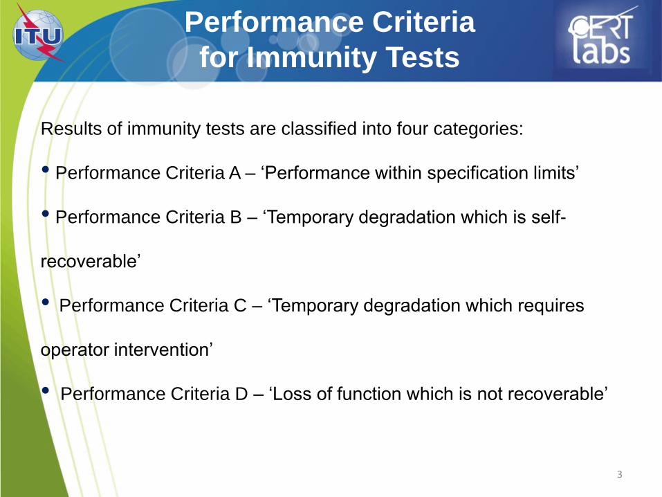
Performance Criteria
for Immunity Tests
Results of immunity tests are classified into four categories:
• Performance Criteria A – ‘Performance within specification limits’
• Performance Criteria B – ‘Temporary degradation which is self-
recoverable’
• Performance Criteria C – ‘Temporary degradation which requires
operator intervention’
• Performance Criteria D – ‘Loss of function which is not recoverable’
ESD
IEC 61000-4-2
4
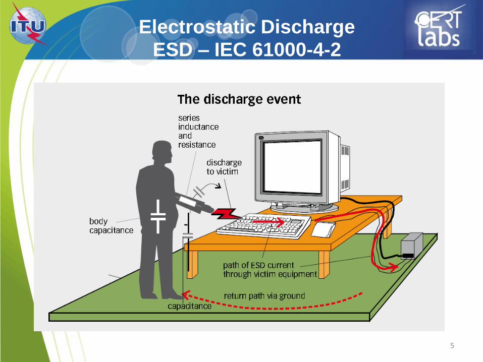
Electrostatic Discharge
ESD – IEC 61000-4-2
5
Electrostatic discharge
(IEC 61000-4-2)
6
• Test purpose
• Evaluate the performance of a device submitted to
human electric discharge
• Needed instruments:
ESD generator
Ground plane (horizontal and vertical)
Isolant surface
470 kΩ loads
7
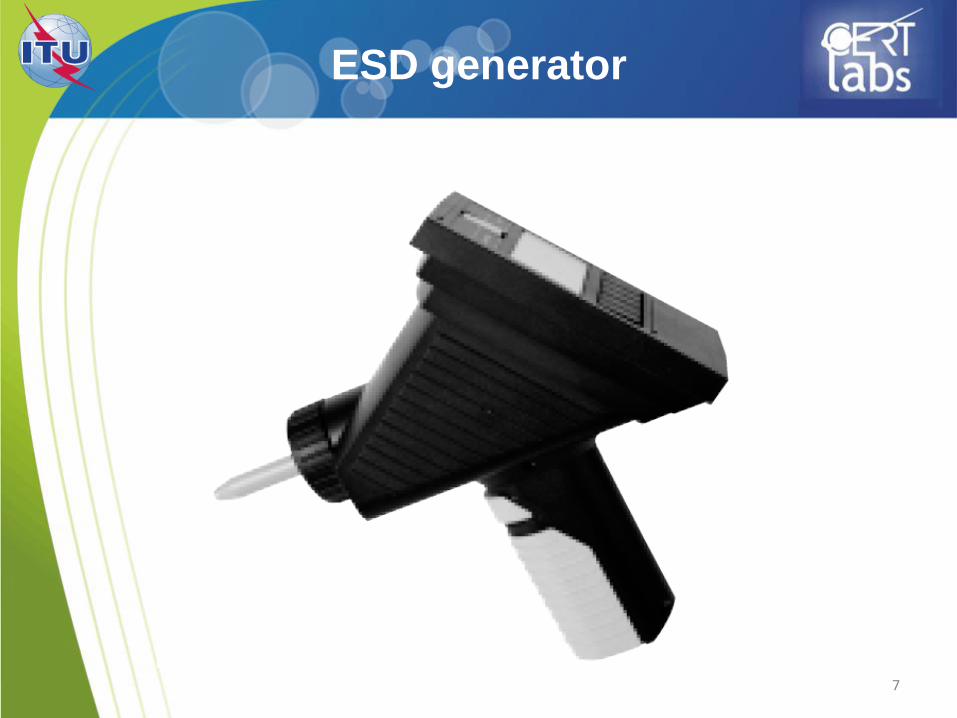
ESD generator
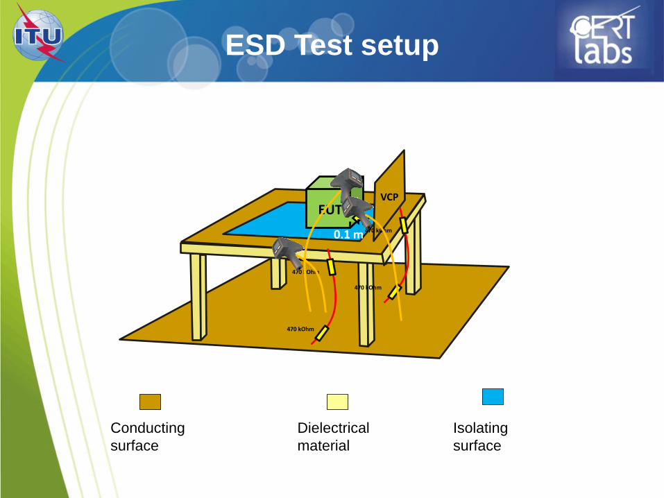
ESD Test setup
EUT
470 kOhm
470 kOhm
0.1 m
VCP
470 kOhm
470 kOhm
Conducting
surface
Dielectrical
material
Isolating
surface
9
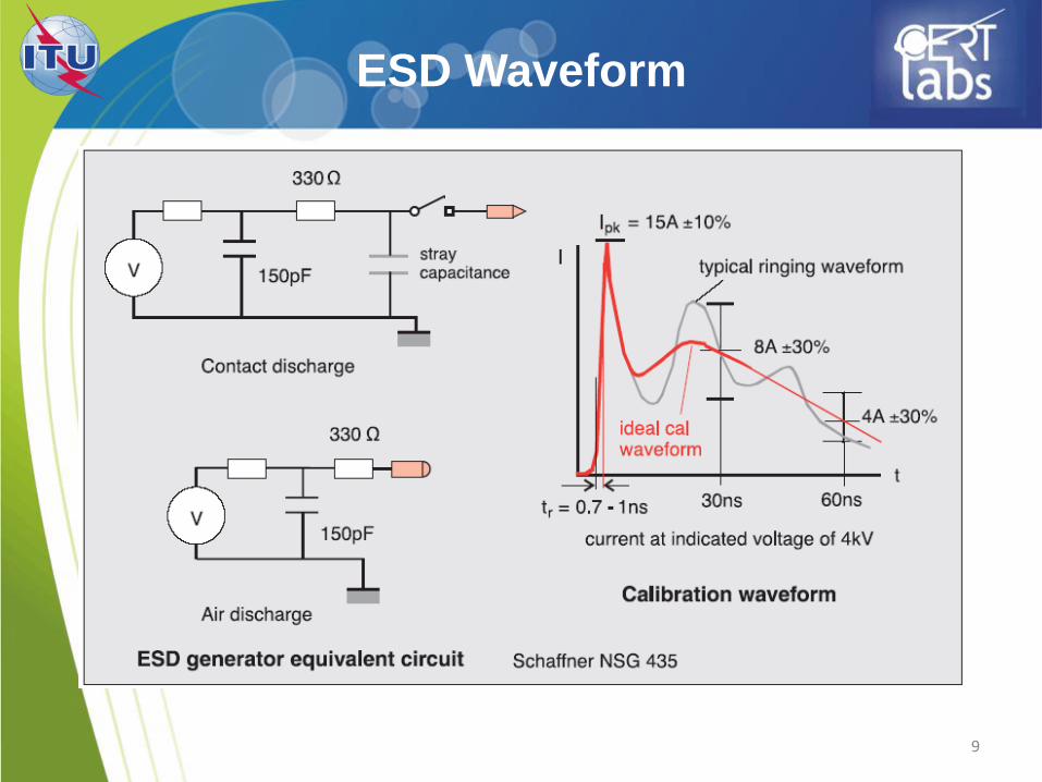
ESD Waveform
10
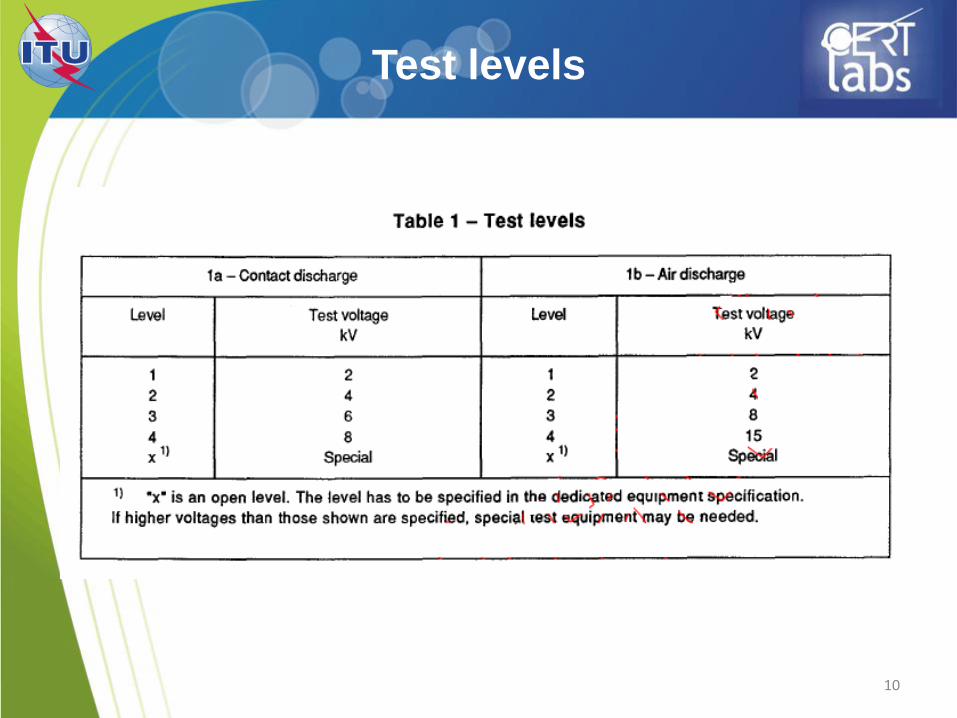
Test levels
11
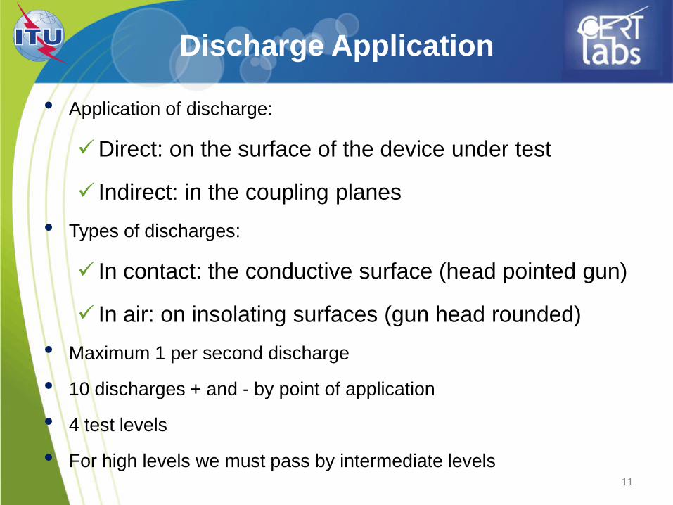
Discharge Application
• Application of discharge:
Direct: on the surface of the device under test
Indirect: in the coupling planes
• Types of discharges:
In contact: the conductive surface (head pointed gun)
In air: on insolating surfaces (gun head rounded)
• Maximum 1 per second discharge
• 10 discharges + and - by point of application
• 4 test levels
• For high levels we must pass by intermediate levels
12
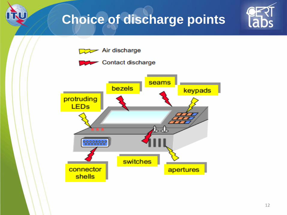
Choice of discharge points
13
• The discharge return cable of the ESD
generator shall be connected to the ground
reference plane. The total length of this cable
is in general 2 m.
Fundamental Principals
14
• In the case of air discharge testing, the climatic
conditions shall be within the following ranges:
ambient temperature: 15 °C to 35 °C;
relative humidity: 30 % to 60 %;
atmospheric pressure: 86 kPa (860 mbar) to 106 kPa
(1 060 mbar).
15
The testing shall be performed by direct and indirect application
of discharges to the EUT according to a test plan. This should
include:
representative operating conditions of the EUT;
whether the EUT should be tested as table-top or floor-standing;
the points at which discharges are to be applied;
at each point, whether contact or air discharges are to be applied;
the test level to be applied;
the number of discharges to be applied at each point for
compliance testing;
whether post-installation tests are also to be applied.
Execution of the test
16
• Link to the standard IEC 61000-4-2
• In the case of contact discharges, the tip of the
discharge electrode shall touch the EUT, before
the discharge switch is operated.
• In the case of air discharges, the round
discharge tip of the discharge electrode shall be
approached as fast as possible (without causing
mechanical damage) to touch the EUT.
Contact/air discharge

Radiated immunity
IEC 61000-4-3
17
18
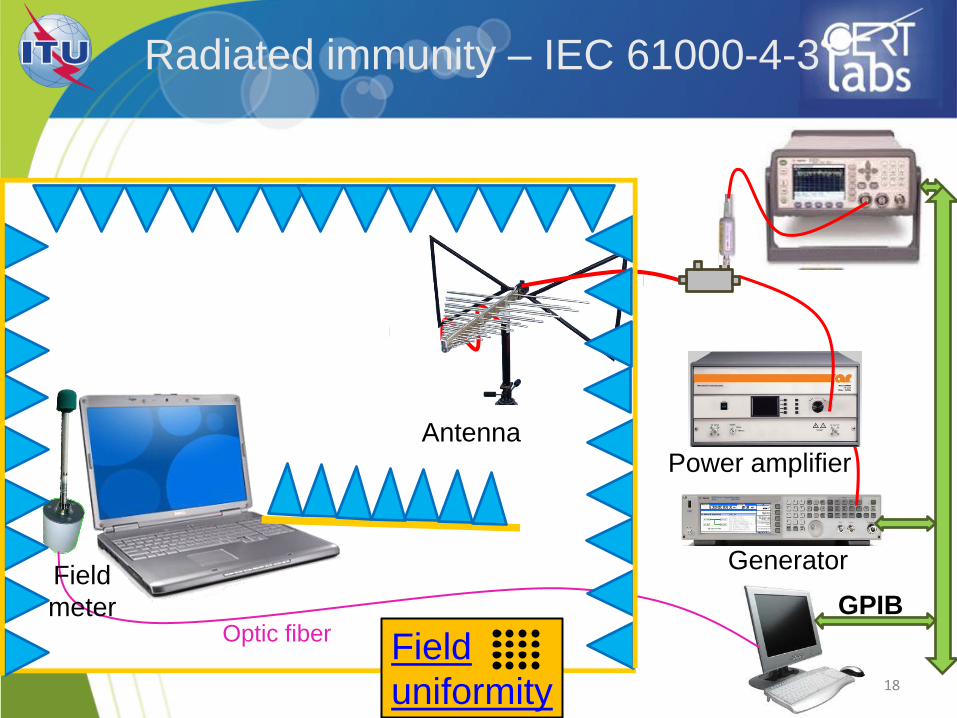
Antenna
Generator
Power amplifier
GPIB Field
meter Optic fiber
Field
uniformity
Radiated immunity – IEC 61000-4-3
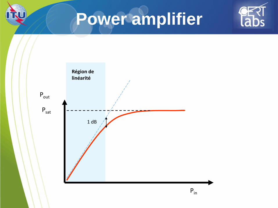
Power amplifier
Pout
Pin
Psat
1 dB
Région de linéarité
Uniform field calibration
• Performed at 1.8 times the desired field strength. • For testing at 10V/m the calibration is run at 18V/m • The reason of running a test at 1.8x the level is to verify
the RF amplifier has the ability to reach the required field when the 80% 1KHz Amplitude Modulation is applied.
• An EMC Lab performing testing at multiple levels 1V/m,
3V/m, 10V/m, 30V/m, and/or others, they need only to perform the calibration at 1.8x the max level they will test to and
then the can scale the power down.
20
Frequency range
• The tests are normally carried out in the
frequency range 800 MHz to 960 MHz and 1.4
GHz to 6 GHz.
• Pause adapted to the device under test
• 80% at 1 kHz modulation
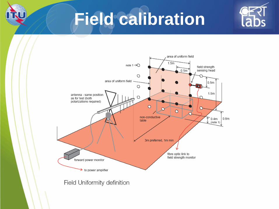
Field calibration
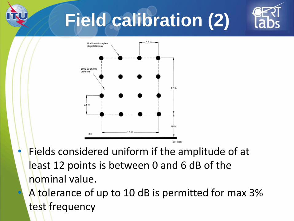
Field calibration (2)
• Fields considered uniform if the amplitude of at least 12 points is between 0 and 6 dB of the nominal value. • A tolerance of up to 10 dB is permitted for max 3% test frequency
EFT
IEC 61000-4-4
24
25
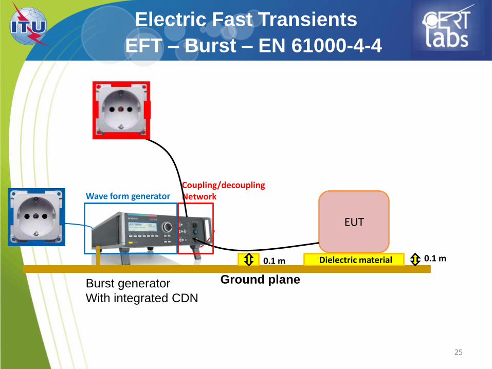
Electric Fast Transients
EFT – Burst – EN 61000-4-4
EUT
Burst generator
With integrated CDN
Wave form generator Coupling/decoupling Network
Ground plane
0.1 m Dielectric material 0.1 m
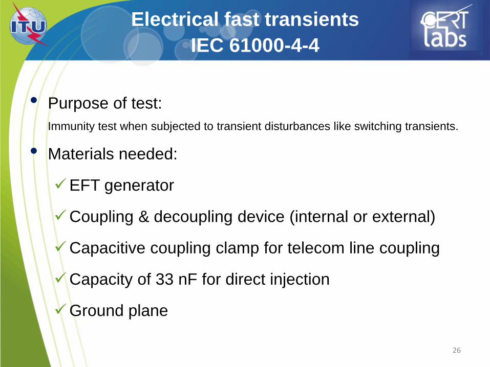
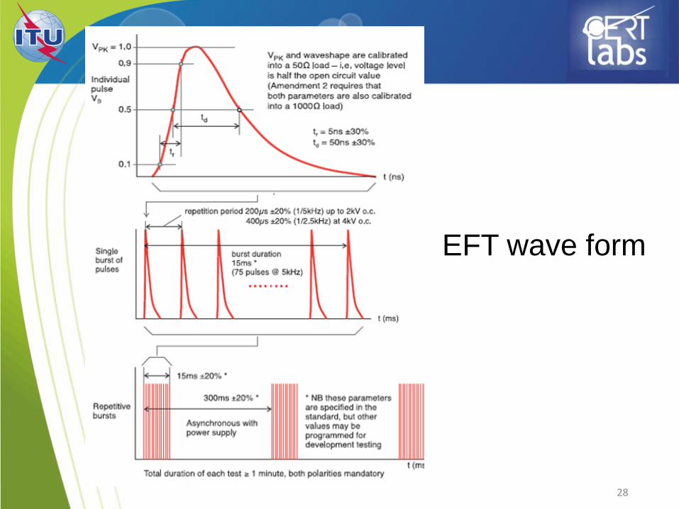
Electrical fast transients
IEC 61000-4-4
26
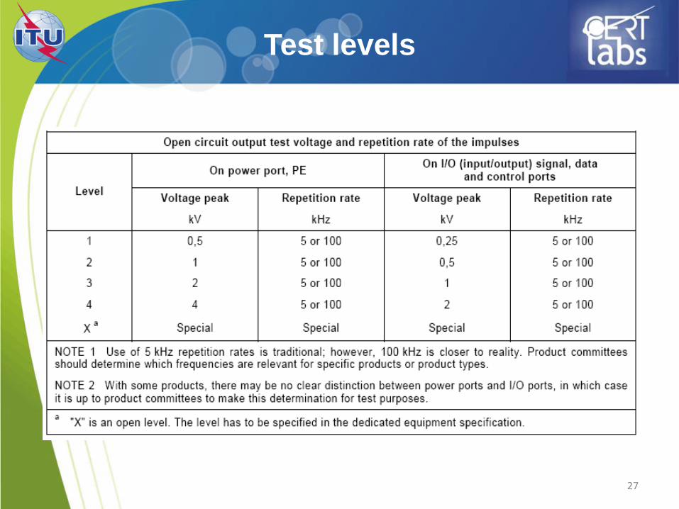
• Purpose of test:
Immunity test when subjected to transient disturbances like switching transients.
• Materials needed:
EFT generator
Coupling & decoupling device (internal or external)
Capacitive coupling clamp for telecom line coupling
Capacity of 33 nF for direct injection
Ground plane
27
Test levels
28
EFT wave form
29
• On each conductor
• For at least 1 min
• polarity + And –
• Test levels and intermediate levels
EFT Application
Test setup
30
• Table-top equipment : EUT located 0,1 m above the
ground plane.
• The test generator and CDN placed directly on, and
connected to, the ground plane.
• All cables connected to the EUT shall be placed on
the insulation support 0,1 m above the ground
reference plane.
31
Test setup
• Either a direct coupling network or a capacitive
clamp shall be used for the application of the test
voltages.
• Decoupling networks shall be used to protect
auxiliary equipment and public networks.
Test procedure
32
• The test procedure includes:
• the verification of the laboratory reference
conditions;
• the preliminary verification of the correct
operation of the equipment;
• the execution of the test;
• the evaluation of the test results.
33
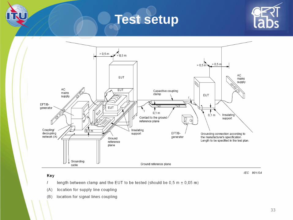
Test setup
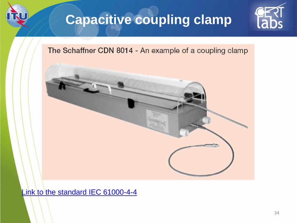
Capacitive coupling clamp
34
Link to the standard IEC 61000-4-4
Surge
IEC 61000-4-5
35
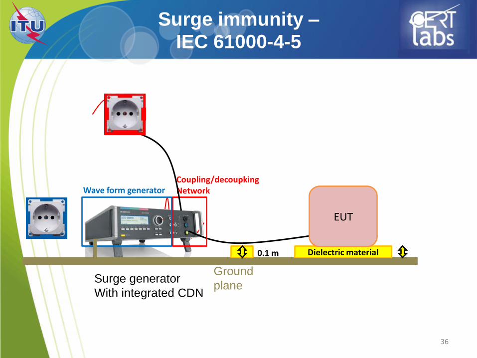
Surge immunity –
IEC 61000-4-5
36
Surge generator
With integrated CDN
Wave form generator Coupling/decoupking Network
Ground
plane
Dielectric material 0.1 m
EUT
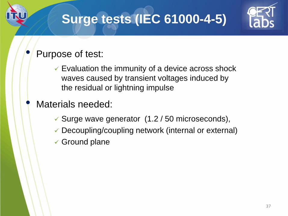
Surge tests (IEC 61000-4-5)
• Purpose of test:
Evaluation the immunity of a device across shock
waves caused by transient voltages induced by
the residual or lightning impulse
• Materials needed:
Surge wave generator (1.2 / 50 microseconds),
Decoupling/coupling network (internal or external)
Ground plane
37
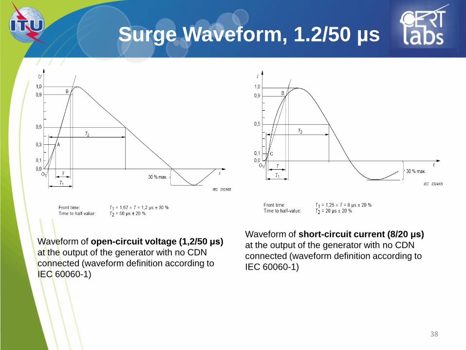
Surge Waveform, 1.2/50 µs
38
Waveform of open-circuit voltage (1,2/50 μs)
at the output of the generator with no CDN
connected (waveform definition according to
IEC 60060-1)
Waveform of short-circuit current (8/20 μs)
at the output of the generator with no CDN
connected (waveform definition according to
IEC 60060-1)
39
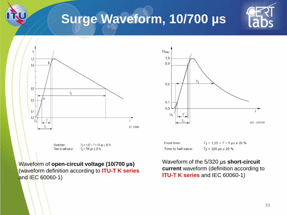
Surge Waveform, 10/700 µs
Waveform of open-circuit voltage (10/700 μs)
(waveform definition according to ITU-T K series
and IEC 60060-1)
Waveform of the 5/320 μs short-circuit
current waveform (definition according to
ITU-T K series and IEC 60060-1)
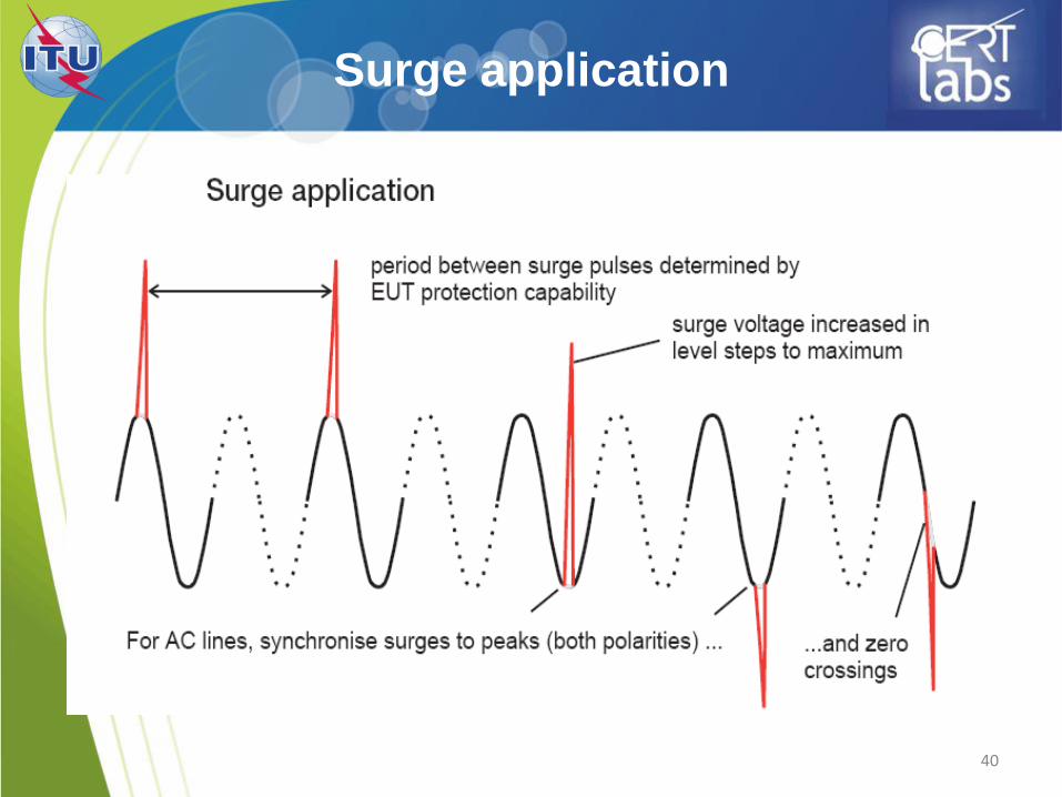
Surge application
40
41
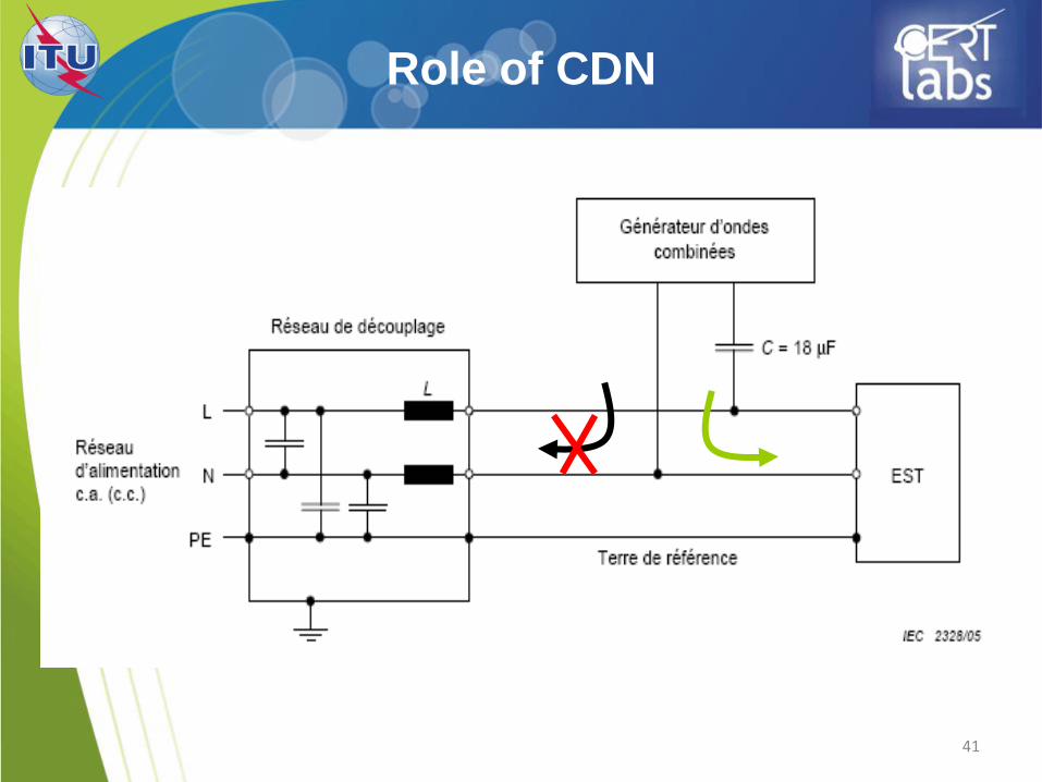
Role of CDN
42
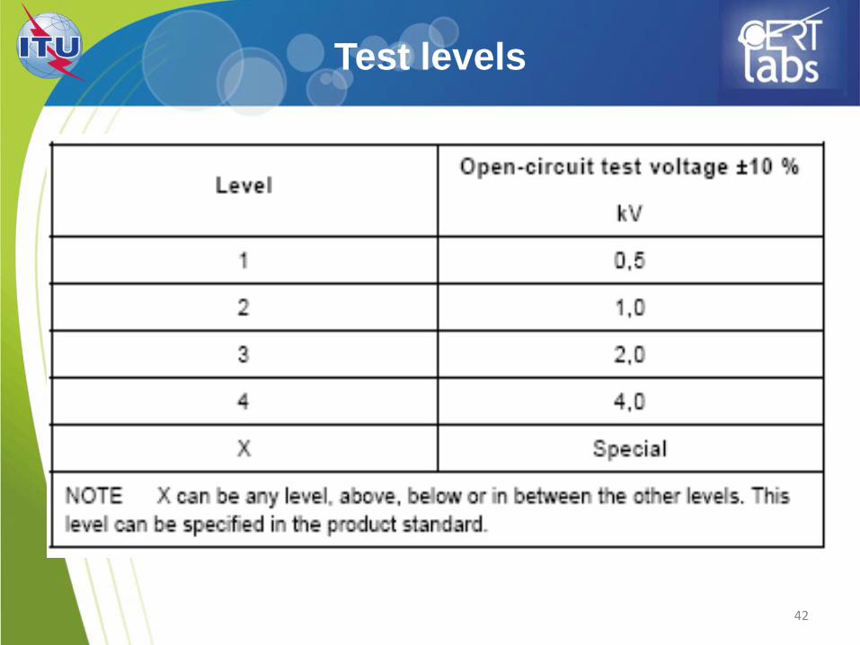
Test levels
43
Surge application
• Differential mode and common mode
• In + and – polarity
• Number of pulses: 5 (for each polarity)
• Phase angles 0 °, 90 ° and 270 °
• Test levels and intermediate levels
44
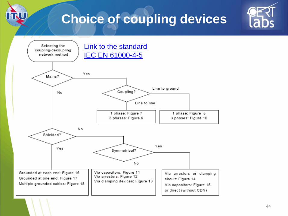
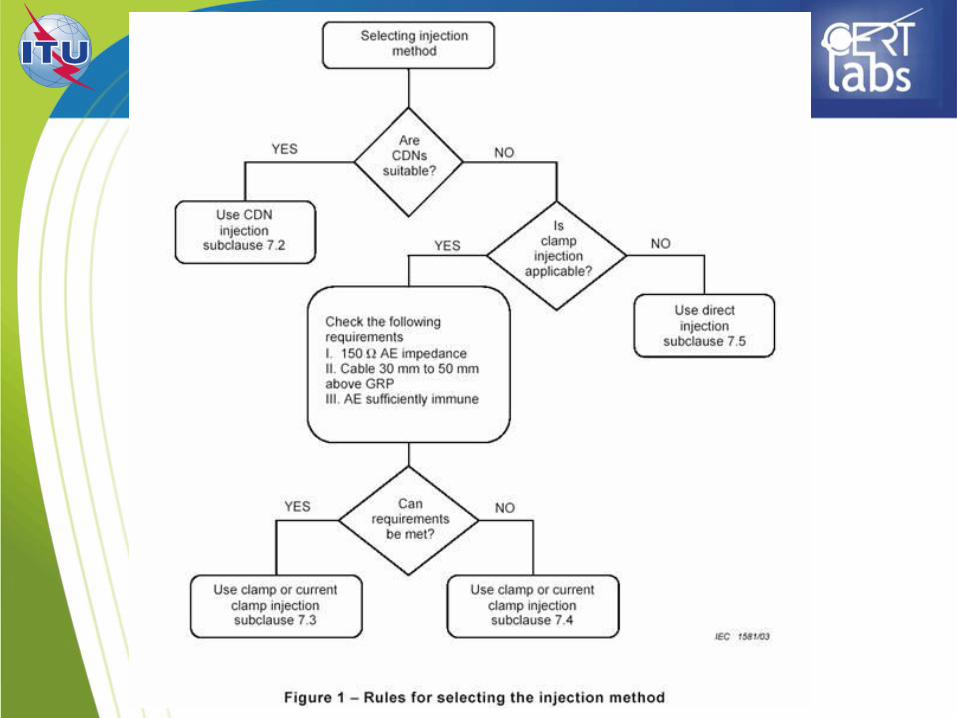
Choice of coupling devices
Link to the standard
IEC EN 61000-4-5
Conducted immunity
IEC 61000-4-6
45
46
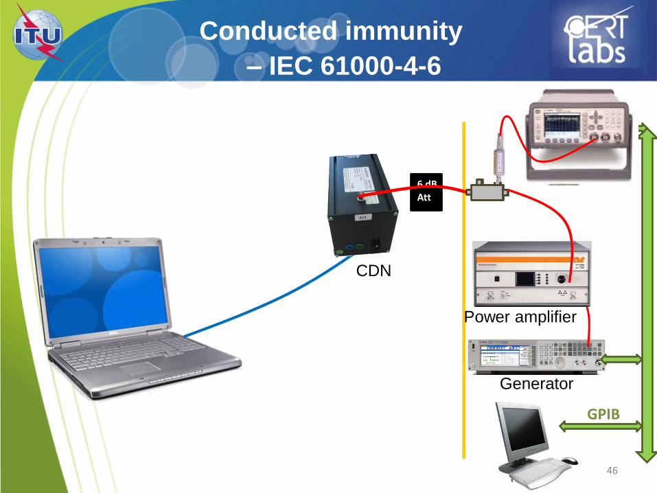
Conducted immunity
– IEC 61000-4-6
Generator
Power amplifier
CDN
6 dB Att
GPIB
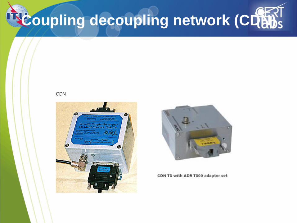
Coupling decoupling network (CDN)
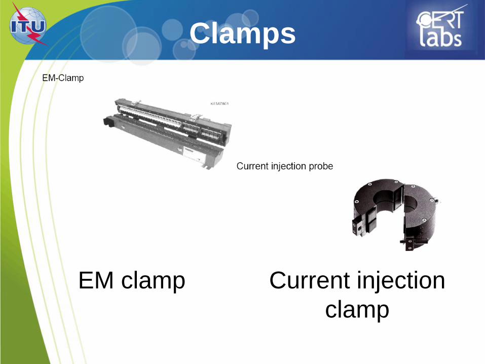
Clamps
EM clamp Current injection
clamp
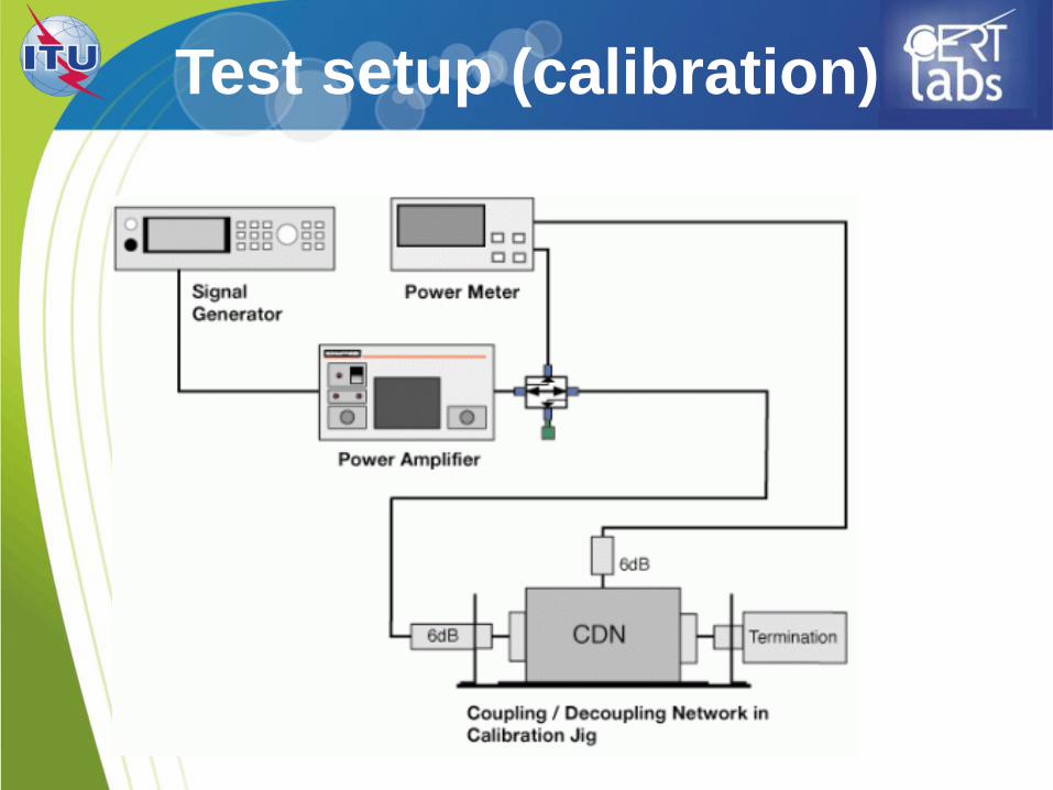
Test setup (calibration)
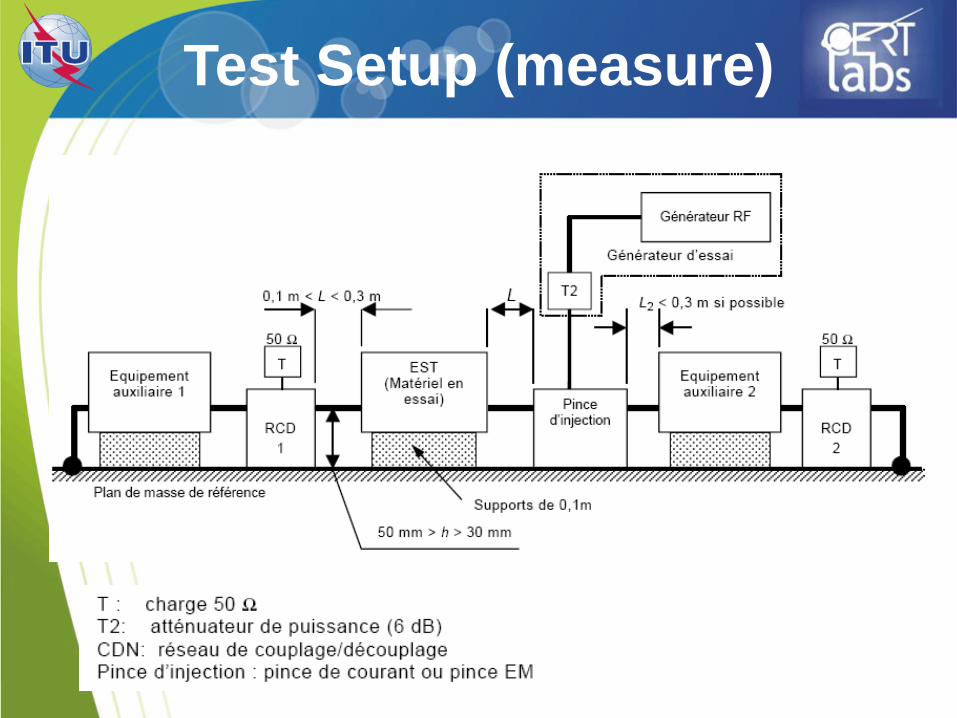
Test Setup (measure)
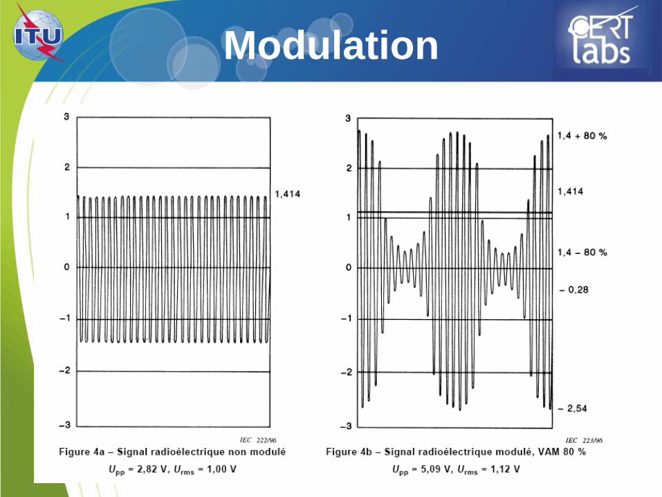
Modulation

Immunity to magnetic fields
IEC 61000-4-8
54
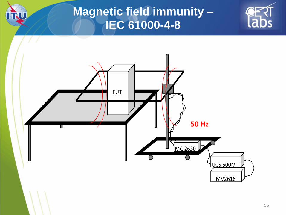
55
Magnetic field immunity –
IEC 61000-4-8
50 Hz
Immunity to voltage dips
and short interruptions
IEC 61000-4-11
56
57
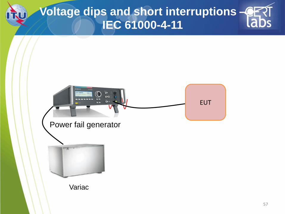
Voltage dips and short interruptions –
IEC 61000-4-11
EUT
Power fail generator
Variac
58
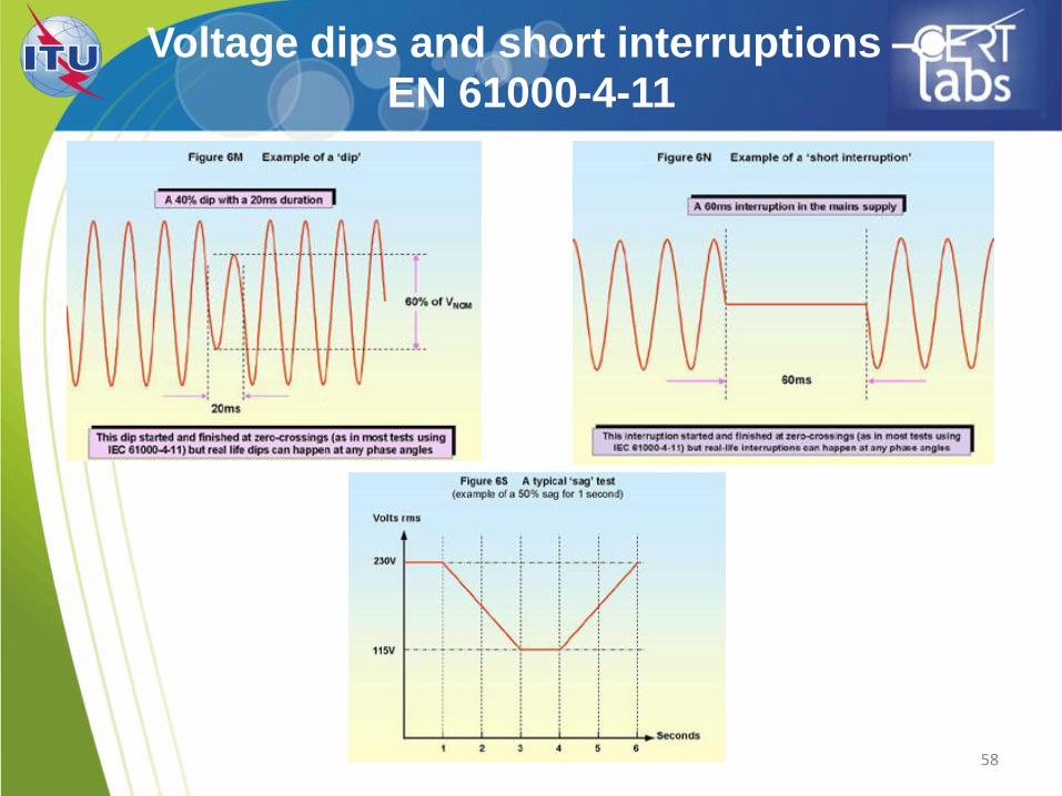
Voltage dips and short interruptions –
EN 61000-4-11
59
Emission tests

Emission
CISPR 22 / EN 55022
60
61
ITE functionnality
• An ITE is able to perform:
Receive data from an external source;
Perform treatments
Provide a result
62
Equipements Classes (1)
• The class B ITE is intended primarily for
use in a residential area and may include:
the devices having no fixed location of use, such as portable battery powered or batteries incorporated;
the telecommunication terminal equipment supplied by a telecommunications network;
personal computers and auxiliary devices connected to them.
63
Equipements Classes(2)
• Class A consists of all other ATI complying
with the limits of disturbance of class
A but not those of class B.
• Can be used in commercial or
industrial environment.

Conducted emissions
CISPR22/EN 55022
64
Required equipments
• For power supply lines:
LISN (Lines Impedance Stabilisation Network)
• For data lines:
ISN (Impedance Stabilisation Network)
• Transient limiter
• EMI receiver or spectrum analyser
• EMI software
66
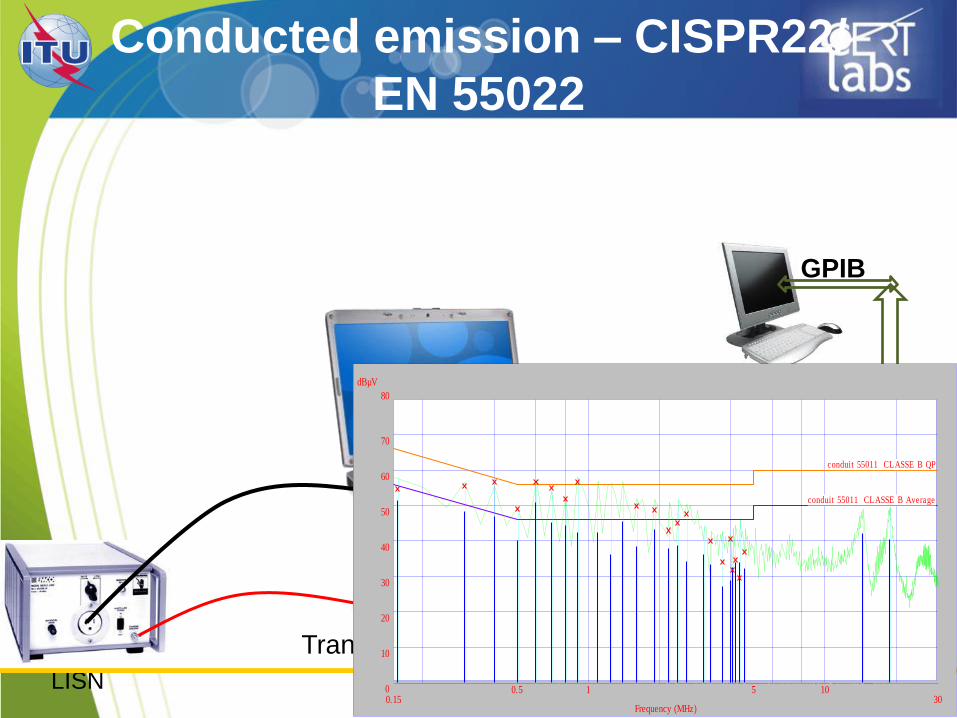
Conducted emission – CISPR22/
EN 55022
LISN
EMI receiver or
spectrum analyser Transient limiter
GPIB
Frequency (MHz)
dBµV
0.15 300.5 1 5 100
80
10
20
30
40
50
60
70
conduit 55011 CLASSE B Average
conduit 55011 CLASSE B QP
67
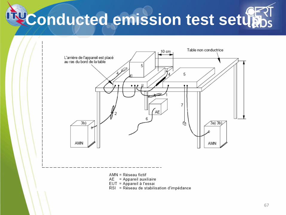
Conducted emission test setup

Conducted emissions
Measurement of conducted electromagnetic
disturbances must be made:
• by means of a measuring receiver
• with a peak detector
• in the frequency range 9 kHz to 30 MHz.
69
Conducted limits
• The EUT shall respect the limits of Tables 1 and
2 which include limits on the mean value and limits
on quasi-peak value
• A receiver is used to average value detection and
a quasi-peak detector
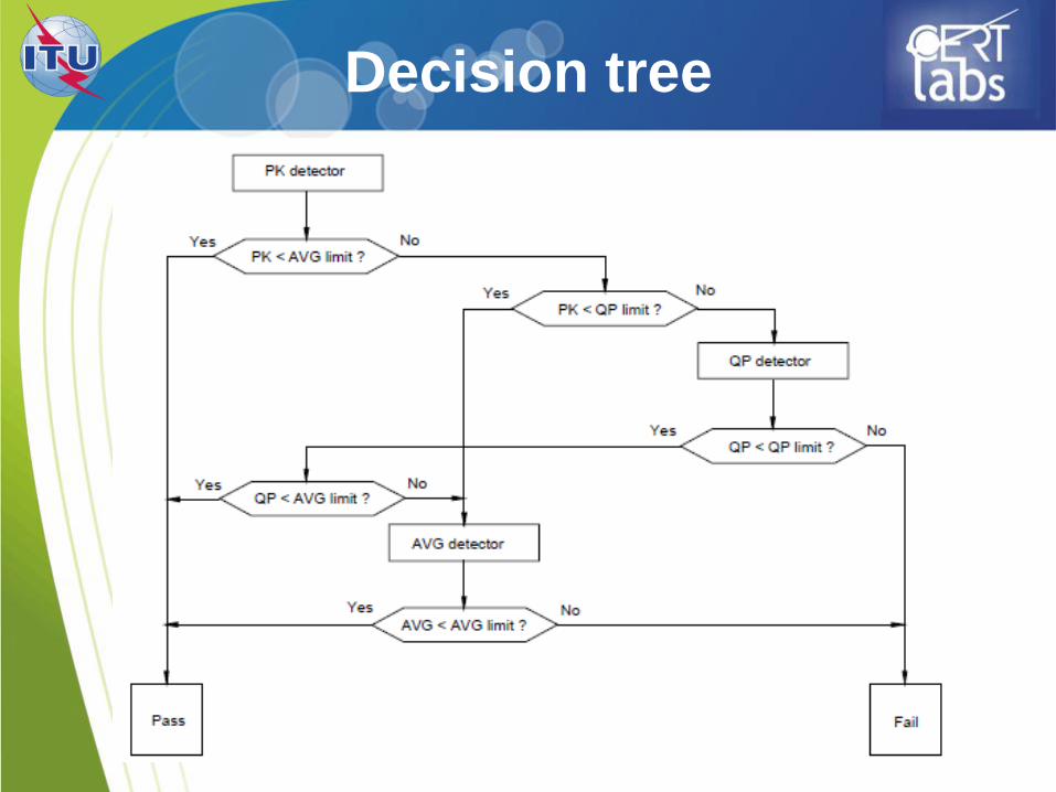
Decision tree
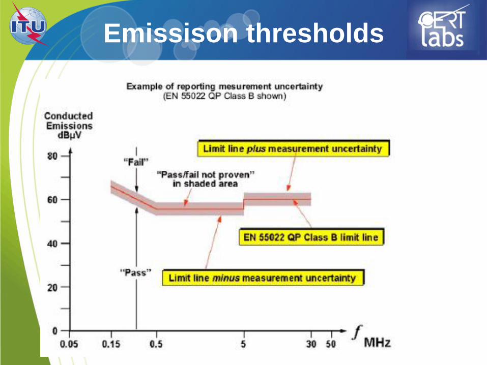
Emissison thresholds
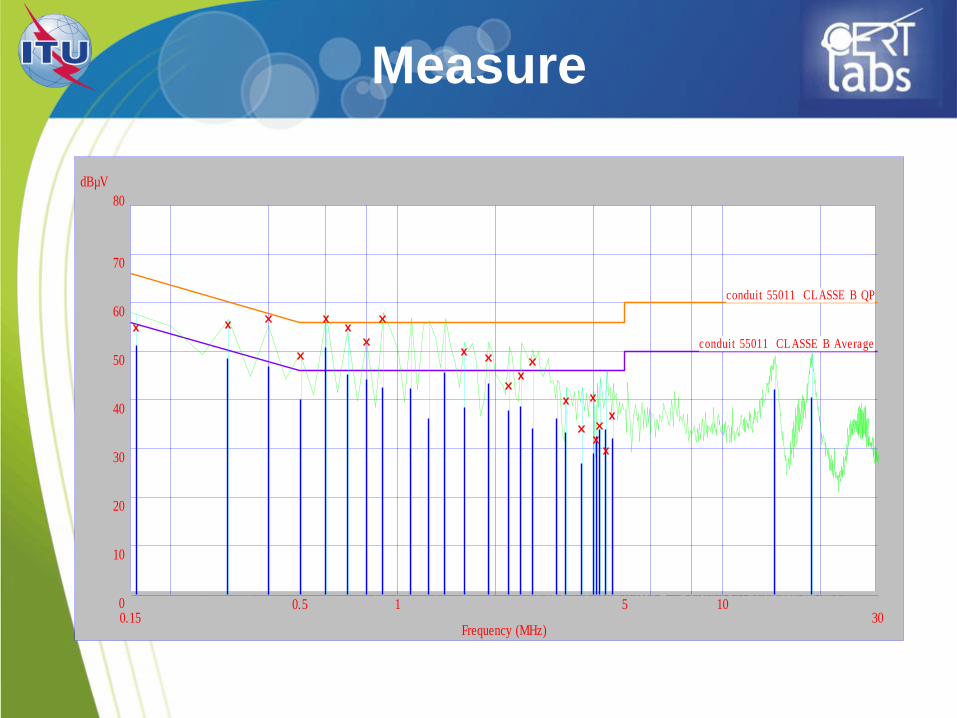
Measure
Frequency (MHz)
dBµV
0.15 300.5 1 5 100
80
10
20
30
40
50
60
70
conduit 55011 CLASSE B Average
conduit 55011 CLASSE B QP
Radiated emissions
CISPR22/EN 55022
Required equipments
• Receiving antennas
• EMI receiver or spectrum analyser
• EMI software
75
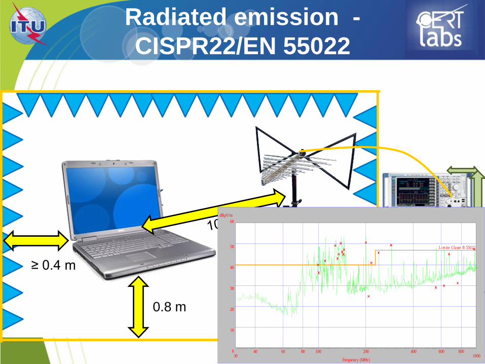
Radiated emission -
CISPR22/EN 55022
EMI receiver or
spectrum
analyser
GPIB
0.8 m
≥ 0.4 m
Frequency (MHz)
dBµV/m
30 100040 60 80 100 200 400 600 8000
60
10
20
30
40
50 Limite Classe B 55022
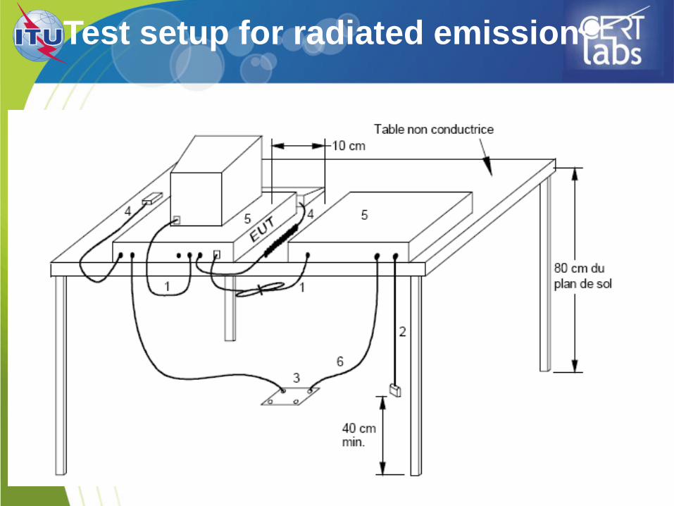
Test setup for radiated emission
Radiated emission
• The measurement of radiated electromagnetic
disturbances must be performed by means of a measuring receiver
equipped with a quasi-peak detector in the frequency
range 30 MHz to 1 GHz or 6 GHz.
• A receiving antenna, associated with a measuring receiver, is placed at a specific distance from the EUT (test equipment)
77
Radiated EM field measure
• Peak measure to determine the most perturbing condition
• Determining antenna polarisation that most generate disturbances
• For every frequency :
Determine the antenna hight that captures the maximum measured level
Determine the angle that generated the maximum of disturbances
78
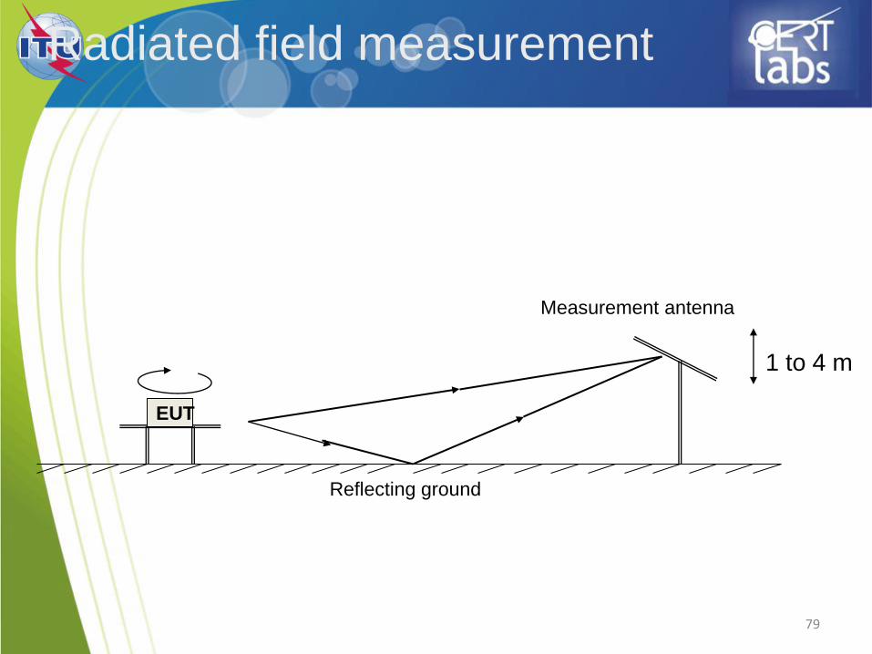
79
EUT
Measurement antenna
Reflecting ground
Radiated field measurement
1 to 4 m
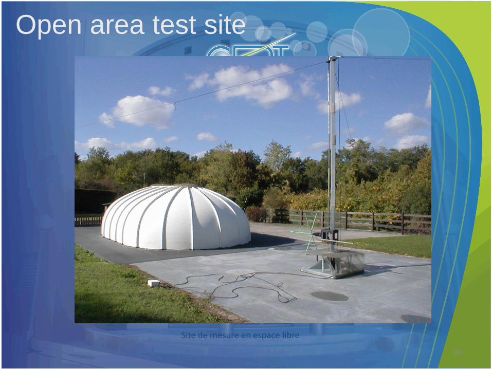
Site de mesure en espace libre
Open area test site
80
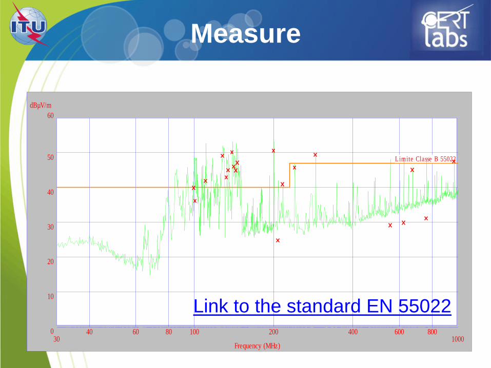
Frequency (MHz)
dBµV/m
30 100040 60 80 100 200 400 600 8000
60
10
20
30
40
50 Limite Classe B 55022
Measure
Link to the standard EN 55022
Harmonics emission
IEC 61000-3-2
82

83
EUT
Harmonics emission – IEC 61000-3-2
Harmonics
analyser Stable
source
Flickers emission
IEC 61000-3-2
84
85
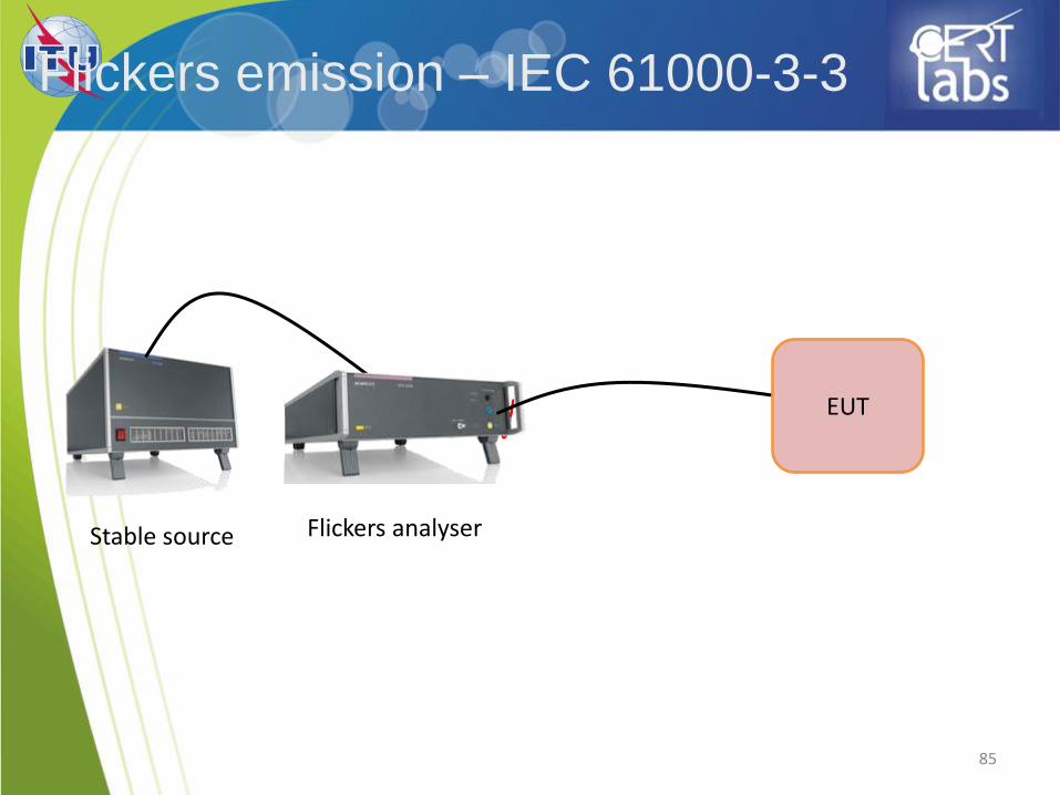
Flickers emission – IEC 61000-3-3
EUT
Flickers analyser Stable source
87
Example of a generic standard
EN 61000-6-1
EMC standards
89
ITU Training on Conformance and Interoperability
for ARB and AFR Regions
CERT, 23-27 June 2014