Embed Size (px)
Citation preview

EMC Amplifiers – Going Beyond the Basics to
Ensure Successful Immunity Tests
Paul Denisowski, Application Engineer Broadband amplifiers are used to generate the high field strengths
required by EMC radiated immunity testing standards. This webinar
focuses on the basics of EMC amplifiers, including a technical overview
as well as a practical discussion of how amplifier class, compression
points, VSWR, foldback, etc. impact performance in real-world scenarios.

Outline
• Amplifiers in EMC testing
• Amplifier fundamentals
• Linearity and compression
• Understanding VSWR
• Protection methods
• Additional considerations
• Summary / question and answer

An Overview of EMC Testing
• Emissions testing (or interference
testing) - measure electromagnetic signals
emitted by the EUT to determine if these
emissions exceed the permissible limits.
• Immunity testing (or susceptibility
testing) - verify a device can function
properly when exposed to (significant)
levels of RF energy.
• There are numerous examples of devices
that have malfunctioned or failed when
exposed to high levels of RF energy -- in
some cases resulting in injury and death.

Amplifiers in EMC Testing
• In immunity testing the device is subjected to
RF over a wide range of frequencies.
• RF energy may be conducted into a device via
its attached cables or be directly picked up
"over-the-air“ from radiated signals.
• Challenges of radiated immunity testing:
– Very high field strengths (3 - 200 V/m) are
required
– Antenna efficiency varies greatly over the
wide frequency ranges
• EMC amplifiers are used to generate the
power needed to create the high field strengths
required in radiated immunity testing.

Amplifier Fundamentals
• An amplifier takes an input signal
and produces an output signal that is
a copy of the input signal, but with
increased amplitude.
• Variety of construction methods:
– Traveling wave tubes (TWTs)
– Klystrons
– Magnetrons
– Transistors
• EMC amplifiers below 6 GHz usually
use solid state RF transistors.

Amplifier Classes of Operation
• The conduction angle is percentage
of the time during which the amplifier is
"amplifying" or conducting power.
• For example:
– Angle = 360° : amplifier conducts
over entire input power cycle
– Angle = 180° : amplifier conducts
over half of input power cycle.
• Higher conduction angles mean higher
linearity (i.e. the output is a more
precise reproduction of the input) but at
the cost of lower efficiency and higher
temperatures.
Vsupply
Vgate

Class A, B and AB
• Amplifiers with a 360°
conduction angle are called
Class A amplifiers
• Amplifiers with a 180°
conduction angle are called
Class B amplifiers.
• Class AB amplifiers have a
conduction angle between
180° and 360°. This
represents a compromise
between the conflicting goals
of linearity and efficiency.

Amplifier classes and EMC
• Class A provides high linearity but low efficiency.
• Class AB amplifiers advantages:
– lighter weight / lower cost
– increased efficiency
– reasonably linear performance
• Class AB disadvantages:
– reduced ability to dissipate heat
– more susceptible to damage resulting from
high VSWR
• Class A amplifiers are generally preferred over
Class AB amplifiers in EMC testing.

Output power
• Output power (specified in watts or dBm) is the most fundamental
performance parameter for any amplifier. Usually a function of input
(drive) power.
• Immunity testing requires output power in the range of hundreds or
thousands of watts to generate the field strengths specified in most
immunity testing standards.
• The gain of an amplifier is simply the ratio of output power over the
input power, usually given in dB.
dBP
Pgain
in
out
log10

Output power vs. field strength
• Amplifiers are specified in terms of their
output power.
• However, the purpose of amplifiers in radiated
immunity testing is to generate a field
strength of a given intensity at a given
distance from the antenna.
• Field strength is a function of many variables.
• The amplifier output power needed to create a
given field strength is highly frequency-
dependent.
• For example, a field strength of 10 V/m may
require 100 watts at one frequency and 1000
watts at a different frequency.

Linearity and compression
• An amplifier is operating in its linear
region when there is a fixed increase in
output power for a given increase in
input power -- i.e. for every N dB
increase in input power there is a N dB
increase in output power.
• When there is no longer a linear
relationship between the increase in
input power and the increase in output
power, the amplifier is said to be in
compression.

Compression point
• Compression is
specified in terms of a
compression point at
a given power level.
• The most commonly
used compression
point is the 1 dB
compression point
(P1dB), where the
actual output power is
1 dB less than the
expected (linear) output
power.

About compression points
• P1dB is the standard measure
of amplifier linearity.
• Some amplifiers are specified
using 2 dB or 3 dB
compression points, even
though harmonics and IMD
are significantly higher at
these points compared to
P1dB.
• Impossible to evaluate the
performance of a 1000W
amplifier if the P1dB is
specified at only 700W.

Consequences of compression
• Operating an amplifier in compression has two consequences:
– Increasing input power no longer results in the same increase in
output power. Eventually the maximum amplifier output power
will be reached regardless of input power.
– Amplifiers in compression produce harmonics and
intermodulation products which increase rapidly and
unpredictably as the amplifier goes further into compression.

Harmonics and intermod
• The presence of harmonics and intermodulation products makes it
very difficult to determine which frequency components are
responsible for undesirable EUT behavior.
• Harmonics usually have lower power than the fundamental, but the
harmonic may actually yield a higher field strength due to the
frequency response of the antenna.

Measuring field strength
• Most field strength probes are not frequency-specific and cannot
determine the presence of harmonics and intermodulation products.
• Frequency-selective devices such as EMI receivers or spectrum
analyzers can be used to detect and measure any harmonics and
intermodulation products present in the transmitted signal.
• Safest way is to use an amplifier with good linearity and to operate
that amplifier within its linear region.

Forward and reflected power
• Maximum power transfer occurs when source and load impedances
are equal (“matched“) and all output is absorbed by the load.
• If load impedance is not the same as the source impedance, some
of the power transmitted towards the load (the forward power) is
returned back to the source (the reflected power).
• This mismatch causes standing waves on the transmission line
between source and load.

Forward and reflected power

Reflection coefficient
• Reflection is normally quantified by means of a reflection
coefficient, Γ, which is a function of the load impedance (ZL) and
the source impedance (Z0).
• Impedances (Z) are complex (R ± jX), frequency-dependent values.
This has a tremendous impact on the selection and use of amplifiers
for radiated immunity testing.
0
0
ZZ
ZZ
L
L

VSWR Formula
• The combination of the forward and reflected waves leads to
standing waves on the transmission line.
• The voltage standing wave ratio (VSWR) is the ratio of peak to
minimum voltage on a transmission line.
• VSWR can be derived from the reflection coefficient Γ.
1
1VSWR

VSWR and % reflected power

Specifying VSWR
• VSWR is most often specified either as a ratio (2:1) or as a
normalized value (2).
• VSWR of 1:1 (1.0) indicates a perfectly matched load.
• Obtaining a (near-)perfect match is highly desirable because it
maximizes power transfer and minimizes reflected power.
• A perfect match (1:1) is rarely obtainable in radiated immunity
testing.

Antennas and VSWR
• EMC amplifiers normally have a
fixed, non-reactive source
impedance (50 or 75 Ω).
• However, the load (antenna)
impedance varies tremendously as a
function of frequency.
• Difficult to design antennas with low
(< 2:0) VSWR over moderately large
frequency ranges.
• Even for well-designed antennas,
VSWR can easily exceed 6:1 over
the nominal operating range.

Multiple antennas and VSWR
• One way to obtain “manageable"
VSWR values over a wide frequency
ranges is to separate the range into
smaller subranges and use a different
antenna over each of these ranges.
• The number of subranges is usually
limited to six or less.
• Common in radiated immunity testing,
but requires switching between
antennas.
• Even with multiple antennas, it can
still be difficult to obtain a "good"
VSWR over even a single subrange.

Matching networks and VSWR
• Another approach: alter the (apparent) impedance of the load.
• Since high VSWR is caused by a significant impedance mismatch,
so-called matching networks are sometimes used in an attempt to
make the load impedance "match" the source impedance.
• Matching networks are used in many applications, but it is difficult to
design matching networks that are effective and/or efficient over
very wide frequency ranges.

Mutual coupling and VSWR
• The antenna has by far the greatest influence on VSWR, but other
factors can also affect the VSWR during radiated immunity testing.
• Interaction or coupling between the EUT and antenna can influence
field strength and VSWR.
• The degree of coupling depends on distance between the EUT and
the antenna, the aspect angle, EUT composition, etc.

Chamber and VSWR
• VSWR can also be affected by
chamber itself.
• Generally the smaller the chamber,
the greater the effect on VSWR.
• There may be a sharp increase in
VSWR when the wavelength of the
transmitted signal becomes close
to one or more linear internal
dimensions of the chamber.
• Size, location, and electrical
characteristics of the ground plane
can also affect VSWR.

Power vs. field strength
• We are interested in field strength,
not power in and of itself.
• The higher the VSWR, the lower the
percentage of amplifier power that is
delivered to the load and the lower the
resulting field strength.
• As VSWR increases, amplifier output
power must also be increased in order
to maintain a given field strength.
• An amplifier faced with high VSWR
may be unable to produce the
necessary output power needed to
generate the desired field strength.

Power leveling
• Creating a uniform field strength across a wide range of frequencies
can be very challenging.
• Power leveling algorithms are often included as part of EMC test
automation environments.
• Algorithms are usually vendor specific – the speed and efficiency of
these proprietary algorithms can vary tremendously between
platforms.

VSWR and amplifier protection
• High levels of reflected power can be very
harmful to an amplifier
• Immediate damage can be caused by
internal arcing or transistor breakdown.
• Damage or degradation of amplifier
performance may also occur more gradually
when reflected energy generates excessive
heat within the amplifier itself.
• Simplest solution is to put a fixed attenuator
in the path. This reduces the level of
reflected power, but also reduces the
transmitted power level.

Foldback
• The most common amplifier protection method is foldback.
• As reflected power increases, output power is decreased.
• However, this also reduces the output power and consequently the
radiated field strength.
• Foldback can protect an amplifier, but reduces performance.

Foldback triggering
• While VSWR describes percent reflected power but absolute level
triggers foldback.
• For example, at VSWR of 6:1 equals 50% reflected power is
reflected. However, 50% of 100 watts is far less damaging than
50% of 1000 watts.
• Foldback should therefore be specified at a given power, not a given
VSWR.

VSWR and open / short circuits
• High VSWR values are often unavoidable during normal radiated
immunity testing.
• Two abnormal situations : short or open circuit.
• Can be the result of equipment failure and/or human error
• In both cases VSWR = infinity : 100% reflected power
• Broadband amplifiers vary tremendously in terms of how long they
can continue to operate without damage when connected to a large
mismatch such as an open or short.

Extreme VSWR event

Handling excessive VSWR
• Excessive VSWR may be encountered
– continuously (open/ short)
– temporarily (e.g. during a frequency sweep).
• Some amplifiers can only deal with short periods of high VSWR,
others are capable of running for extended periods (hours) into an
open, shorted, or high VSWR load.
• Especially important in automated testing, when quick manual
intervention may not be possible.

Additional amplifier considerations
• Numerous other important considerations in EMC amplifiers:
– Heat dissipation
– Noise level
– Construction method
– Control and operation
– Sample ports
– Safety
– Modularity
– Power density

Heat dissipation
• Amplifiers generate heat in proportion
to output power and VSWR.
• Consequences of excessive heat:
– degrade amplifier performance
– reduce the operational life
– permanent amplifier damage.
• Heat can also adversely affect nearby
external devices.
• Cooling methods:
– air cooling
– liquid-based cooling

Noise level
• Air-cooled systems typically require
fans.
• Fan noise can be continuous and
substantial.
• High noise levels can lead to health,
safety, and other workplace issues.
• A properly designed and efficient air
cooling system should not require
extremely loud and/or bulky fans.

Construction method
• Manual amplifier assembly leads to variability between amplifiers
and greater risk of faults.
• Modern manufacturing techniques greatly improve quality,
consistency, and robustness.

Control and operation
• Amplifiers may be operated as standalone, manually-adjusted
devices or as part of a larger test automation environment.
• Amplifiers should have easy-to-understand controls, preferably with
visual indications of parameters like output power and VSWR.
• Remotely access and control is extremely useful as well.

Sample ports
• Directional power meters can be
used in-line to make direct
measurements of forward and
reflected power.
• Built-in sample ports on an amplifier
make this task both simpler and
safer.
• Directivity and degree of isolation
between ports can differ
substantially between amplifiers.

Safety features
• Most important safety feature is an interlock.
• Interlocks are used to automatically turn off power (e.g. when a
chamber door is opened).
• Multiple independent interlocks can be a useful feature for amplifier
systems having multiple paths to different chambers.

Modularity
• Modular amplifiers can be
configured for different (or multiple)
frequency bands.
• Modularity provides advantages
both in terms of flexibility as well
as ease of replacement / upgrade.
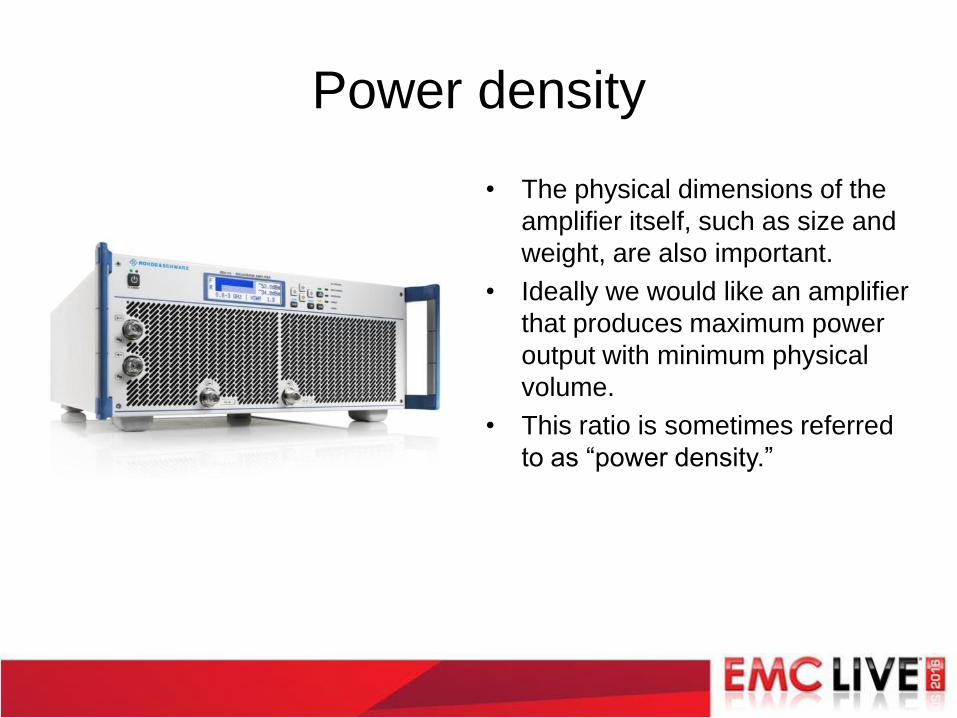
Power density
• The physical dimensions of the
amplifier itself, such as size and
weight, are also important.
• Ideally we would like an amplifier
that produces maximum power
output with minimum physical
volume.
• This ratio is sometimes referred
to as “power density.”
Summary / conclusion
• EMC immunity testing requires the use of high-
power, broadband amplifiers for generating high
levels of RF field strength.
• Amplifiers must be able to provide sufficient output
power under widely varying VSWR conditions.
• Amplifiers must be able to deliver this power with
good linearity (i.e. without going into compression).
• Amplifiers must be able to handle high levels of
reflected power for both performance and safety
reasons.
• Additional usability considerations also play an
important role.

Don’t miss our Test Bootcamp!
November 16, 2016
www.emclive2016.com
Thanks for attending!