Embed Size (px)
Citation preview

DESIGN STANDARDS
EMBANKMENT NO. 13DAMS
CHAPTER 2 EMBANKMENT DESIGN
UNITED STATESDEPARTMENT OF THE INTERIOR
BUREAU OF RECLAMATIONTECHNICAL SERVICE CENTER
DENVER, COLORADO

UNITED STATES DEPARTMENT OF THE INTERIOR
Bureau of Reclamation Denver Office
Denver, Colorado 80225-0007 I3
TRANSMITTAL OF DESIGN STANDARDS Change No. DS- /
Standards Number and Title:
Design Standard No. 13 - EMBANKMENT DAMS Chapter 2 - Embankment Design
Insert Sheets: Remove Sheets:
Chapter 2 Chapter 2 (DRAFT)
Summary of Chanses:
This document is the final approved version of a draft document that was applied, reviewed, and revised during a trial period.
The contents of this design standard are based on information presented in Desion of Small Dams, published by the U.S. Department of the Interior, Bureau of Reclamation, 1987 [l]. Specifically, information in chapter 6 - "Earthfill Darns," and in chapter 7 - "Rockfill Dams" was used extensively. Passages have been edited and information added so that this chapter is applicable to large and small dams and reflects current practice.
The above change has been made in the Design Standards
Signature Date

DESIGN STANDARD NO. 13
EMBANKMENT DAMS
CHAPTER 2 - EMBANKMENT DESIGN
UNITED STATES DEPARTMENT OF THE INTERIOR
BUREAU OF RECLAMATIONASSISTANT COMMISSIONER
ENGINEERING AND RESEARCH
DENVER, COLORADO
EMBANKMENT DAMS Chapter 2 - Embankment Design
DS-13(2)-9 - 6/1/92 iii
CONTENTS
Paragraph Page
INTRODUCTION 2.1 Purpose . . . . . . . . . . . . . . . . . . . . . . . . . . . . . . . . . . . . . . . . . . . . . . . . . . . . . . . . . . . . . . . . . . . . . . . . . 12.2 Scope . . . . . . . . . . . . . . . . . . . . . . . . . . . . . . . . . . . . . . . . . . . . . . . . . . . . . . . . . . . . . . . . . . . . . . . . . 12.3 Deviations From Standard . . . . . . . . . . . . . . . . . . . . . . . . . . . . . . . . . . . . . . . . . . . . . . . . . . . . . . . . . . 12.4 Revisions of Standard . . . . . . . . . . . . . . . . . . . . . . . . . . . . . . . . . . . . . . . . . . . . . . . . . . . . . . . . . . . . 12.5 Applicability . . . . . . . . . . . . . . . . . . . . . . . . . . . . . . . . . . . . . . . . . . . . . . . . . . . . . . . . . . . . . . . . . . . . 1
Section I
EARTHFILL DAMS 2.6 Origin and Development . . . . . . . . . . . . . . . . . . . . . . . . . . . . . . . . . . . . . . . . . . . . . . . . . . . . . . . . . . . . 22.7 Selection of Type of Earthfill Dam . . . . . . . . . . . . . . . . . . . . . . . . . . . . . . . . . . . . . . . . . . . . . . . . . . . . 3
A. General . . . . . . . . . . . . . . . . . . . . . . . . . . . . . . . . . . . . . . . . . . . . . . . . . . . . . . . . . . . . . . . . . . . . . . 3B. Diaphragm Type . . . . . . . . . . . . . . . . . . . . . . . . . . . . . . . . . . . . . . . . . . . . . . . . . . . . . . . . . . . . . . 4C. Homogeneous Type . . . . . . . . . . . . . . . . . . . . . . . . . . . . . . . . . . . . . . . . . . . . . . . . . . . . . . . . . . . 4D. Zoned Embankment Type . . . . . . . . . . . . . . . . . . . . . . . . . . . . . . . . . . . . . . . . . . . . . . . . . . . . . . . 5
2.8 Design Data . . . . . . . . . . . . . . . . . . . . . . . . . . . . . . . . . . . . . . . . . . . . . . . . . . . . . . . . . . . . . . . . . . . . . 72.9 Criteria for Design . . . . . . . . . . . . . . . . . . . . . . . . . . . . . . . . . . . . . . . . . . . . . . . . . . . . . . . . . . . . . . . 7
FOUNDATION DESIGN 2.10 General . . . . . . . . . . . . . . . . . . . . . . . . . . . . . . . . . . . . . . . . . . . . . . . . . . . . . . . . . . . . . . . . . . . . . . . . 82.11 Rock Foundations . . . . . . . . . . . . . . . . . . . . . . . . . . . . . . . . . . . . . . . . . . . . . . . . . . . . . . . . . . . . . . . . 10
A. General . . . . . . . . . . . . . . . . . . . . . . . . . . . . . . . . . . . . . . . . . . . . . . . . . . . . . . . . . . . . . . . . . . . . . . 10B. Foundation Surface Treatment . . . . . . . . . . . . . . . . . . . . . . . . . . . . . . . . . . . . . . . . . . . . . . . . . . . . 11C. Grouting . . . . . . . . . . . . . . . . . . . . . . . . . . . . . . . . . . . . . . . . . . . . . . . . . . . . . . . . . . . . . . . . . . . . . 12D. Cutoffs . . . . . . . . . . . . . . . . . . . . . . . . . . . . . . . . . . . . . . . . . . . . . . . . . . . . . . . . . . . . . . . . . . . . . . 12E. Drainage . . . . . . . . . . . . . . . . . . . . . . . . . . . . . . . . . . . . . . . . . . . . . . . . . . . . . . . . . . . . . . . . . . . . . 12
2.12 Sand and Gravel Foundations . . . . . . . . . . . . . . . . . . . . . . . . . . . . . . . . . . . . . . . . . . . . . . . . . . . . . . . 13A. General . . . . . . . . . . . . . . . . . . . . . . . . . . . . . . . . . . . . . . . . . . . . . . . . . . . . . . . . . . . . . . . . . . . . . . 13B. Underseepage . . . . . . . . . . . . . . . . . . . . . . . . . . . . . . . . . . . . . . . . . . . . . . . . . . . . . . . . . . . . . . . . . 14C. Seepage Control . . . . . . . . . . . . . . . . . . . . . . . . . . . . . . . . . . . . . . . . . . . . . . . . . . . . . . . . . . . . . . . 14D. Drainage Blankets, Toe Drains, and Drainage Trenches . . . . . . . . . . . . . . . . . . . . . . . . . . . . . . . . 15E. Relief Wells . . . . . . . . . . . . . . . . . . . . . . . . . . . . . . . . . . . . . . . . . . . . . . . . . . . . . . . . . . . . . . . . . . 15F. Cutoff Trenches . . . . . . . . . . . . . . . . . . . . . . . . . . . . . . . . . . . . . . . . . . . . . . . . . . . . . . . . . . . . . . . . 15
2.13 Silt and Clay Foundations . . . . . . . . . . . . . . . . . . . . . . . . . . . . . . . . . . . . . . . . . . . . . . . . . . . . . . . . . . 16A. General . . . . . . . . . . . . . . . . . . . . . . . . . . . . . . . . . . . . . . . . . . . . . . . . . . . . . . . . . . . . . . . . . . . . . . 16B. Saturated Foundations . . . . . . . . . . . . . . . . . . . . . . . . . . . . . . . . . . . . . . . . . . . . . . . . . . . . . . . . . . . 16C. Relatively Dry Foundations . . . . . . . . . . . . . . . . . . . . . . . . . . . . . . . . . . . . . . . . . . . . . . . . . . . . . . 17D. Liquefaction . . . . . . . . . . . . . . . . . . . . . . . . . . . . . . . . . . . . . . . . . . . . . . . . . . . . . . . . . . . . . . . . . 17E. Seepage Control . . . . . . . . . . . . . . . . . . . . . . . . . . . . . . . . . . . . . . . . . . . . . . . . . . . . . . . . . . . . . . . 17
Chapter 2 - Embankment Design EMBANKMENT DAMS
DS-13(2)-9 - 6/1/92 iv
EMBANKMENT DESIGN
2.14 Static Stability . . . . . . . . . . . . . . . . . . . . . . . . . . . . . . . . . . . . . . . . . . . . . . . . . . . . . . . . . . . . . . . . . . . . 182.15 Seepage and Leakage Through Embankments . . . . . . . . . . . . . . . . . . . . . . . . . . . . . . . . . . . . . . . . . . . 192.16 Utilization of Materials From Structural Excavation . . . . . . . . . . . . . . . . . . . . . . . . . . . . . . . . . . . . . . 222.17 Zoning . . . . . . . . . . . . . . . . . . . . . . . . . . . . . . . . . . . . . . . . . . . . . . . . . . . . . . . . . . . . . . . . . . . . . . . . . . 26
A. General . . . . . . . . . . . . . . . . . . . . . . . . . . . . . . . . . . . . . . . . . . . . . . . . . . . . . . . . . . . . . . . . . . . . . . 26B. Diaphragm Type . . . . . . . . . . . . . . . . . . . . . . . . . . . . . . . . . . . . . . . . . . . . . . . . . . . . . . . . . . . . . . 29C. Homogeneous Dams . . . . . . . . . . . . . . . . . . . . . . . . . . . . . . . . . . . . . . . . . . . . . . . . . . . . . . . . . . . . 29D. Zoned Embankments . . . . . . . . . . . . . . . . . . . . . . . . . . . . . . . . . . . . . . . . . . . . . . . . . . . . . . . . . . . . 30E. Transitions . . . . . . . . . . . . . . . . . . . . . . . . . . . . . . . . . . . . . . . . . . . . . . . . . . . . . . . . . . . . . . . . . . . . 31
2.18 Seismic Design . . . . . . . . . . . . . . . . . . . . . . . . . . . . . . . . . . . . . . . . . . . . . . . . . . . . . . . . . . . . . . . . . . . 31
EMBANKMENT DETAILS 2.19 Crest Details . . . . . . . . . . . . . . . . . . . . . . . . . . . . . . . . . . . . . . . . . . . . . . . . . . . . . . . . . . . . . . . . . . . . . 31
A. General . . . . . . . . . . . . . . . . . . . . . . . . . . . . . . . . . . . . . . . . . . . . . . . . . . . . . . . . . . . . . . . . . . . . . . 31B. Width . . . . . . . . . . . . . . . . . . . . . . . . . . . . . . . . . . . . . . . . . . . . . . . . . . . . . . . . . . . . . . . . . . . . . . . 32C. Drainage . . . . . . . . . . . . . . . . . . . . . . . . . . . . . . . . . . . . . . . . . . . . . . . . . . . . . . . . . . . . . . . . . . . . . 32D. Camber . . . . . . . . . . . . . . . . . . . . . . . . . . . . . . . . . . . . . . . . . . . . . . . . . . . . . . . . . . . . . . . . . . . . . . 32E. Surfacing . . . . . . . . . . . . . . . . . . . . . . . . . . . . . . . . . . . . . . . . . . . . . . . . . . . . . . . . . . . . . . . . . . . . . 33F. Public Safety . . . . . . . . . . . . . . . . . . . . . . . . . . . . . . . . . . . . . . . . . . . . . . . . . . . . . . . . . . . . . . . . . . 33G. Zoning . . . . . . . . . . . . . . . . . . . . . . . . . . . . . . . . . . . . . . . . . . . . . . . . . . . . . . . . . . . . . . . . . . . . . . 35H. Typical Crest Details . . . . . . . . . . . . . . . . . . . . . . . . . . . . . . . . . . . . . . . . . . . . . . . . . . . . . . . . . . . . 35
2.20 Freeboard . . . . . . . . . . . . . . . . . . . . . . . . . . . . . . . . . . . . . . . . . . . . . . . . . . . . . . . . . . . . . . . . . . . . . . . 362.21 Upstream Slope Protection . . . . . . . . . . . . . . . . . . . . . . . . . . . . . . . . . . . . . . . . . . . . . . . . . . . . . . . . . 36
A. General . . . . . . . . . . . . . . . . . . . . . . . . . . . . . . . . . . . . . . . . . . . . . . . . . . . . . . . . . . . . . . . . . . . . . . 36B. Selection of Type of Protection . . . . . . . . . . . . . . . . . . . . . . . . . . . . . . . . . . . . . . . . . . . . . . . . . . . 36C. Dumped Rock Riprap . . . . . . . . . . . . . . . . . . . . . . . . . . . . . . . . . . . . . . . . . . . . . . . . . . . . . . . . . . . 38D. Soil-Cement . . . . . . . . . . . . . . . . . . . . . . . . . . . . . . . . . . . . . . . . . . . . . . . . . . . . . . . . . . . . . . . . . . 38
2.22 Downstream Slope Protection . . . . . . . . . . . . . . . . . . . . . . . . . . . . . . . . . . . . . . . . . . . . . . . . . . . . . . . 382.23 Surface Drainage . . . . . . . . . . . . . . . . . . . . . . . . . . . . . . . . . . . . . . . . . . . . . . . . . . . . . . . . . . . . . . . . . 392.24 Flared Slope at Abutments . . . . . . . . . . . . . . . . . . . . . . . . . . . . . . . . . . . . . . . . . . . . . . . . . . . . . . . . . . 40

EMBANKMENT DAMS Chapter 2 - Embankment Design
DS-13(2)-9 - 6/1/92 v
Section II
ROCKFILL DAMS 2.25 Origin and Usage . . . . . . . . . . . . . . . . . . . . . . . . . . . . . . . . . . . . . . . . . . . . . . . . . . . . . . . . . . . . . . . . . 412.26 Definition and Types of Rockfill Dams . . . . . . . . . . . . . . . . . . . . . . . . . . . . . . . . . . . . . . . . . . . . . . . . 422.27 Impervious Elements Other Than Clay Cores . . . . . . . . . . . . . . . . . . . . . . . . . . . . . . . . . . . . . . . . . . . 43
FOUNDATION DESIGN
2.28 Foundation Requirements and Treatment . . . . . . . . . . . . . . . . . . . . . . . . . . . . . . . . . . . . . . . . . . . . . . 442.29 Membrane Cutoffs . . . . . . . . . . . . . . . . . . . . . . . . . . . . . . . . . . . . . . . . . . . . . . . . . . . . . . . . . . . . . . . . 46
EMBANKMENT DESIGN 2.30 Selection of Rock Materials . . . . . . . . . . . . . . . . . . . . . . . . . . . . . . . . . . . . . . . . . . . . . . . . . . . . . . . . . 502.31 Embankment Sections . . . . . . . . . . . . . . . . . . . . . . . . . . . . . . . . . . . . . . . . . . . . . . . . . . . . . . . . . . . . . 522.32 Stability . . . . . . . . . . . . . . . . . . . . . . . . . . . . . . . . . . . . . . . . . . . . . . . . . . . . . . . . . . . . . . . . . . . . . . . . . 582.33 Placement of Rockfill Materials . . . . . . . . . . . . . . . . . . . . . . . . . . . . . . . . . . . . . . . . . . . . . . . . . . . . . 592.34 Compaction . . . . . . . . . . . . . . . . . . . . . . . . . . . . . . . . . . . . . . . . . . . . . . . . . . . . . . . . . . . . . . . . . . . . . . 59
MEMBRANE DESIGN 2.35 Impervious Core . . . . . . . . . . . . . . . . . . . . . . . . . . . . . . . . . . . . . . . . . . . . . . . . . . . . . . . . . . . . . . . . . 602.36 Reinforced Concrete . . . . . . . . . . . . . . . . . . . . . . . . . . . . . . . . . . . . . . . . . . . . . . . . . . . . . . . . . . . . . . . 612.37 Asphaltic Concrete . . . . . . . . . . . . . . . . . . . . . . . . . . . . . . . . . . . . . . . . . . . . . . . . . . . . . . . . . . . . . . . . 632.38 Steel Facings . . . . . . . . . . . . . . . . . . . . . . . . . . . . . . . . . . . . . . . . . . . . . . . . . . . . . . . . . . . . . . . . . . . . 652.39 Timber Planking . . . . . . . . . . . . . . . . . . . . . . . . . . . . . . . . . . . . . . . . . . . . . . . . . . . . . . . . . . . . . . . . . . 662.40 Geomembranes . . . . . . . . . . . . . . . . . . . . . . . . . . . . . . . . . . . . . . . . . . . . . . . . . . . . . . . . . . . . . . . . . . . 66
Appendix
REFERENCES

Chapter 2 - Embankment Design EMBANKMENT DAMS
DS-13(2)-9 - 6/1/92 vi
FIGURES
No. Title
1 Effects of Drainage . . . . . . . . . . . . . . . . . . . . . . . . . . . . . . . . . . . . . . . . . . . . . . . . . . . . . . . . . . . . . 6
2 Use of Random Fill Materials Within Embankments . . . . . . . . . . . . . . . . . . . . . . . . . . . . . . . . . . . 25
3 Designers Proposed Materials Distributions, New Waddel Dam - Stage II . . . . . . . . . . . . . . . . . . 27
4 Crest, Camber, and Slope Protection Details - McPhee Dam . . . . . . . . . . . . . . . . . . . . . . . . . . . . 34
5 Effect of Upstream Membrane on Embankment Resistance to Sliding . . . . . . . . . . . . . . . . . . . . . 45
6 Details of Asphaltic-Concrete Membrane at Cutoff Wall . . . . . . . . . . . . . . . . . . . . . . . . . . . . . . . 47
7 Details of (A) Concrete Cutoff Wall and (B) Doweled Cutoff Slab for a Concrete Membrane . . . . . . . . . . . . . . . . . . . . . . . . . . . . . . . . 48
8 Detail of Steel Plate Membrane at Cutoff Wall . . . . . . . . . . . . . . . . . . . . . . . . . . . . . . . . . . . . . . . . 49
9 Grain Size Distribution for Modeled Rockfill Materials . . . . . . . . . . . . . . . . . . . . . . . . . . . . . . . . 52
10 Effect of Maximum Particle Size on the Angle of Internal Friction . . . . . . . . . . . . . . . . . . . . . . . 55
11 Shearing Resistance of Rockfill from Large Triaxial Tests . . . . . . . . . . . . . . . . . . . . . . . . . . . . . 56

EMBANKMENT DAMS Chapter 2 - Embankment Design
DS-13(2)-9 - 6/1/92 1
2.1INTRODUCTION
PURPOSE
.1 The purpose of this chapter is to give basic guidance for the design of embankment dams within the Bureau ofReclamation.
SCOPE
.2 Design procedures and concepts, with direction to appropriate chapters within Design Standard No. 13 -Embankment Dams for specific methods or analyses, are presented for both earth and rockfill dams. Thisguideline is limited to design procedures for rolled-fill type construction. This type of placement is now beingused almost exclusively in the construction of embankment dams, to the exclusion of semihydraulic andhydraulic fills and dumped rockfills.
DEVIATIONS FROM STANDARD
.3 Design of embankment dams within the Bureau of Reclamation should conform to this standard. If deviationsfrom the standard are required, the rationale for the deviation should be presented in the technicaldocumentation for the design. The technical documentation is to be approved by the Geotechnical Engineeringand Embankment Dams Branch.
REVISIONS OF STANDARD
.4 This standard has had a 1-year-minimum trial period prior to initial release. It will be reviewed and revisedperiodically as its use indicates the need. Comments and suggested revisions should be sent to D-3620 or D-3521.
APPLICABILITY
.5 These standards apply to all embankment dams (earth or rockfill dams) designed by the Bureau of Reclamation.

Chapter 2 - Embankment Design EMBANKMENT DAMS
1 Bracketed numbers [#] identify reference documents contained in the appendix.
DS-13(2)-9 - 6/1/92 2 SECTION I - EARTHFILL DAMS
2.6SECTION I
EARTHFILL DAMS
ORIGIN AND DEVELOPMENT
.6 Embankments for the storage of water for irrigation, as attested to both by historians and archaeologists, havebeen used since the early days of civilization. Some of the structures built in antiquity were of considerable size. One earthfill dam 11 miles (17.7 km) long, 70 feet (21.3 m) high, and containing about 17 million cubic yards(13 x 106 m3) of embankment was completed in Ceylon in the year 504 B.C. Rockfill dams are generallyconceded to have had their origin over 100 years ago during the California Gold Rush [2].1 Today, as in thepast, the embankment dam continues to be the most common type of dam, principally because its constructioninvolves utilization of natural local materials with a minimum of stockpiling and processing.
Until modern times, all embankment dams were designed by empirical methods. Empirical procedures have agreat value and, for many aspects of geotechnical practice, they remain as the primary design and analysis tool. However, the engineering literature is replete with accounts of failures [3, 4, 5] of embankment dams and thesefailures compelled the realization that totally empirical methods must be replaced by rational engineeringprocedures in both design and construction. One of the first to suggest that the slopes for earthfill dams beselected on an analytical basis was Bassell in 1907 [6]. However, little progress was made on the developmentof rational design procedures until the 1930's. The rapid advancement of the science of soil mechanics sincethen has resulted in the development of greatly improved procedures for the design of embankment dams.
These procedures include:
A. thorough preconstruction investigations of foundation conditions and materials for construction,
B. application of engineering analyses and experiences to design,
C. carefully planned and controlled methods of construction, and
D. carefully planned and designed instrumentation and monitoring systems.
Threaded throughout the Plan, Design, Construct, Operate, and Maintain process for an embankment dam is thephilosophy that design is not complete until the dam is accomplishing its purpose and has proven itself safethrough several cycles of operation.
EMBANKMENT DAMS Chapter 2 - Embankment Design
DS-13(2)-9 - 6/1/92 3 SECTION I - EARTHFILL DAMS
2.7
As a result of rational engineering procedures, a few embankment dams have been constructed to heights greaterthan 1,000 feet (300 m) above their foundations, and hundreds of large rolled embankment dams have beenconstructed in the past 50 years with a very good success record.
GENERAL COMMENTS ON EARTHFILL DAMS
.7 General
A. General. - The selection of type of dam is discussed in Chapter 1 of Design Standard No. 13. When thisprocedure leads to the selection of an earthfill dam, a further decision must be made as to the type of earthfilldam: diaphragm, homogeneous, or zoned.
The major portion of the embankment is constructed in successive, rolled-fill layers. It is desirable to conditionimpervious and semi-impervious materials to contain the proper moisture content by irrigation in borrow pits,required excavation, or stockpiles so that very little moisture has to be added on the fill surface.
After moisture conditioning, material from borrow pits/quarries and that which is suitable from excavation forother structures is delivered to the embankment, usually by trucks, scrapers, bottom dumps, or occasionally bybelt conveyors. It is then spread by motor-patrols or bulldozers to form layers of limited thickness. Additionalmoisture is added as necessary by sprinkling and the material disked as necessary to break up clods, distributemoisture, and scarify the preceding layer and then the layer is thoroughly compacted by appropriate rolling.
The designer assumes certain construction methods and equipment usage for construction of the embankment. The success of his design is dependent upon implementation of these assumptions, and it is therefore necessaryto monitor construction to ensure appropriate equipment usage and construction methods. These considerationsare discussed in detail in Chapter 10, Design Standard No. 13.

Chapter 2 - Embankment Design EMBANKMENT DAMS
DS-13(2)-9 - 6/1/92 4 SECTION I - EARTHFILL DAMS
2.7B
Diaphragms
B. Diaphragm type. - In this type of section, the bulk of the embankment is constructed of pervious material(sand, gravel, or rock) and a thin diaphragm of impermeable material is provided to form the water barrier. Theposition of this diaphragm may vary from a membrane on the upstream face to a centrally located diaphragm. The diaphragm or membrane may consist of asphaltic concrete, portland cement concrete, metal, orgeomembrane. Internal diaphragms have the disadvantage of not being readily available for inspection oremergency repair if they are ruptured due to material flaw or settlement of the dam or its foundation.
If the bulk of material comprising the diaphragm-type dam is rock, the dam is classified as a rockfill dam, thedesign of which is discussed in paragraphs 2.25 through 2.39.
Homogeneous
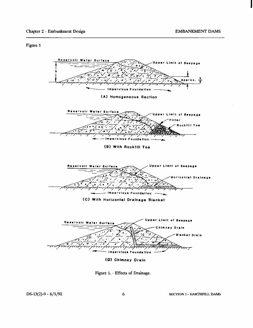
C. Homogeneous type. - A purely homogeneous type of dam is composed of a single kind of material (exceptfor the slope protection). The material comprising the dam must be sufficiently impervious to provide anadequate water barrier. Soils meeting this requirement generally have shear strengths such that the slopes of thedam must be relatively flat for stability. To avoid sloughing, the upstream slope must be flat enough to maintainstability if rapid drawdown of the reservoir after long-term storage is anticipated. The downstream slope mustbe flat enough to provide embankment stability when the reservoir is filled and the bulk of the dam becomessaturated. For a completely homogeneous section on an impervious foundation, seepage will emerge on thedownstream slope regardless of the slope and the impermeability if the reservoir level is maintained for a longperiod of time. Under such conditions, the downstream slope eventually will be affected by seepage to a heightof roughly one-third the depth of the reservoir pool, as shown on figure 1(A). However, in practice, whether ornot seepage exits on the downstream face depends on the permeability of the foundation and embankment andthe reservoir operation.
Although formerly very common, the purely homogeneous section-type dam has been replaced by a modifiedhomogeneous section in which internally placed pervious materials control seepage and the saturation (phreaticsurface) within the dam, thus permitting much steeper slopes. The modification of the homogeneous type ofsection by means of drainage furnishes a greatly improved design. The modified-homogeneous type of dam isapplicable in localities where readily available soils show little variation in permeability, and soils of contrastingpermeabilities are available only in minor amounts or at considerably greater cost. Some recent applications aredams on compaction shales of low strength where very wide berms were provided. The effect of drainageprovided at the downstream toe in a modified homogeneous dam is shown on figure 1.

EMBANKMENT DAMS Chapter 2 - Embankment Design
DS-13(2)-9 - 6/1/92 5 SECTION I - EARTHFILL DAMS
2.7D
Theoretically, rock toes or drainage blankets as shown on figures 1(B) and 1(C) will lower the phreatic surface. However, these features are not designed to intercept seepage or leakage (and possible piping) that can progressalong cracks that may form after fill placement or to intercept more pervious, or loosely compacted, or poorlybonded lifts that might inadvertently occur during construction. Another consideration is the fact thatembankments with soils placed in layers are inherently much more pervious horizontally than vertically causinga tendency for seepage to advance more rapidly and further horizontally. Figure 1(D) shows a chimney drainthat is designed to intercept these potential deficiencies. In recent years, use of the chimney drain has becomealmost standard practice in all homogeneous type dams and should be included in all Reclamation dams unlessvery specific circumstances preclude the need.
Another method of improving and collecting drainage is the installation of pipe drains. These are normally usedin conjunction with the horizontal drainage blanket or toe drain. Pipe drains should only be located in areaswhere they can be inspected, maintained, and accessed for repair without threat to embankment slope stability.
Zoned
D. Zoned embankment type. - As opposed to a modified homogeneous dam, zoned dams are usuallyconstructed in areas where there is availability of several material types such as clays, silts, sands, gravels, androck. Advantage is taken of this availability by placing different materials in various zones so that their bestproperties are used most beneficially and their poor properties are mitigated. A zoned earthfill dam typically hasa central impervious core flanked by transition zones upstream, filters and drains downstream, and then outerzones or shells composed of gravelfill, rockfill, or random fill considerably stronger than the core. Dependingon the gradation of available materials, transitions may not be necessary. The shells enclose, support, andprotect the impervious core, transitions, filters, and drains; the upstream pervious zone affords strength forstability against rapid drawdown; and the downstream zone provides strength to buttress the core and filters sothat steeper (more economical) slopes can be used. The upstream transition, if necessary because of a verypervious shell, provides protection against erosion of the core during drawdown and against cracking of thecore. The filters and drains downstream control through seepage and leakage through any cracks in the centralimpervious core. The dam is considered to be a thin core dam if the impervious zone has a horizontal width lessthan 10 feet (3 m) at any elevation below reservoir level or a ratio of hydraulic head to horizontal width of 2.0 orgreater. This ratio should not be greater than 4 without special analyses and provisions to control seepage andhigh seepage exit gradients through the impervious core and its foundation.
Chapter 2 - Embankment Design EMBANKMENT DAMS
Figure 1
(A) Homogeneous Section
c- IIIIP*r”lo”* Fo”nd.*lon -
(El With Ftockfill Toe
w I~~*r”lo”* Fo”nd.tlon -
(C) With Horizontal Drainage Blanket
(0) Chimney Drain
Figure 1. - Effects of Drainage.
DS-13(2)-9 - 6/l/92 6

EMBANKMENT DAMS Chapter 2 - Embankment Design
DS-13(2)-9 - 6/1/92 7 SECTION I - EARTHFILL DAMS
2.7D
The shells and transitions preferably consist of sand, gravel, cobbles, or rock, or mixtures of these materials. The impervious core is constructed from more impervious fine-grained soils such as silts, clays, sandy silts,sandy clays, and gravelly clays, or mixtures thereof. Although not as desirable, fat clays and gravelly silts havealso been used for the impervious zone. Gravelly clays, sandy clays, and lean clays are the most desirableimpervious materials. The filters and drains are generally processed from available sands and gravels and mustmeet filter criteria with surrounding materials (Chapter 5 of Design Standard No. 13). An example of a zonedembankment is given in figure 1, Chapter 1, of Design Standard No. 13 - Embankment Dams. Chapters 4, 5, 8,and 9 of Design Standard No. 13 cover design of the various zones.
A dam with an impervious core of moderate width composed of strong material and with pervious outer shellsmay have relatively steep outer slopes, limited only by the strength of the foundation material, the stability of theembankment itself, and maintenance considerations. Conditions that tend to increase stability may becontrolling in the choice of a design cross section even if a longer haul is necessary to obtain such embankmentmaterials.
If a variety of soils are readily available, a zoned embankment type will generally be chosen because it is asuperior design from both stability and seepage performance aspects. Zoned dams (as discussed later) alsoafford better ability to use material in the embankment section from required excavation. Materials that areclosest to the dam and require the least processing should be used fully for the best economy.
DESIGN DATA
.8 The data required from investigation of foundations and sources of construction materials for the design of anembankment dam are discussed in Chapter 12 of Design Standard No. 13, the Earth Manual [47], and theGeology Handbooks [44 and 45]. The extent of required data and methods of obtaining the data will begoverned by the nature of the project and the purpose of the design; that is, whether the design is intended as abasis for a cost estimate to determine project feasibility, for construction, or some other purpose. The extent ofinvestigations of foundations and sources of construction material will also be governed by the complexity of thesituation and purpose of the design.
CRITERIA FOR DESIGN
.9 The basic objective of design is to produce a satisfactory functional structure at a minimum total cost. Consideration must be given to maintenance requirements so that economies achieved in the initial cost ofconstruction will not result in excessive maintenance costs. The latter costs will vary with the provisions ofupstream and downstream slope protection, availability of materials for future maintenance and repair, drainagefeatures, and the type of appurtenant structures and mechanical equipment.

Chapter 2 - Embankment Design EMBANKMENT DAMS
DS-13(2)-9 - 6/1/92 8 SECTION I - EARTHFILL DAMS
2.10
For minimum cost, the dam must be designed for maximum utilization of the most economical materialsavailable, including materials which must be excavated for its foundation and for appurtenant structures. Thetypes of earthfill dams are illustrated in Chapter 1 of Design Standard No. 13.
An earthfill dam must be safe and stable during all phases of construction and operation of the reservoir. Minimum requirements to accomplish this are listed in Chapter 1 of Design Standard No. 13 - EmbankmentDams. This requires defensive design measures and usually some redundancy because of the potential hazard ofmost dams. For example, control of seepage and leakage requires the use of an impervious zone of some kindwithin the embankment and usually through pervious zones of the foundation. Additionally, filters and drainagefeatures are required to control seepage or leakage that may find its way through impervious zones. Inearthquake regions, the filters and drains are given additional widths in case of cracking or displacement duringan earthquake. Toe drains are usually an added measure to ensure seepage control and, on pervious foundations,relief wells are sometimes judged necessary to control seepage deeper in the foundation.
An earthfill dam designed to meet the requirements listed in Chapter 1 will safely fulfill project objectivesprovided proper construction methods and control are achieved. The design procedures and guidelinesnecessary to meet the requirements of these criteria are provided in various other chapters of Design StandardNo. 13 - Embankment Dams.
FOUNDATION DESIGN
GENERAL
.10 The term "foundation" as used herein includes both the valley floor and the abutments upon which theembankment will be built. The essential requirements of a foundation for an earthfill dam are that it providestable support for the embankment under all conditions of saturation and loading and that it provide sufficientresistance to seepage to prevent excessive loss of water.
Although the foundation is not actually designed, certain provisions for benefication are provided in designs toensure that the essential requirements will be met. Each foundation presents its own separate and distinctproblems requiring corresponding special treatment and preparation. Various methods for stabilization of weakfoundations, reduction of seepage in permeable foundations, shaping to reduce differential settlement toacceptable levels, and types and locations of devices for the interception of underseepage must be adapted tolocal conditions.

EMBANKMENT DAMS Chapter 2 - Embankment Design
DS-13(2)-9 - 6/1/92 9 SECTION I - EARTHFILL DAMS
2.10
Recent surveys indicate that about 12 percent of embankment dam failures and about 40 percent of accidents toembankment dams can be attributed to the foundation [32]. These figures indicate the importance ofunderstanding the foundation. The foundation must be adequately explored to characterize the properties of thefoundation. The data from the exploration program is interpreted by engineering geologists and must reveal subsurface conditions to permit safe and economical design of foundation treatment. The exploration programshould be a continuing process (see total design process [33]) that begins with inception of the project andcarries through construction. The program should build on data from previous investigations as the designprogresses. It is guided and adjusted by geologic interpretation of the data. The accuracy of the geologicpicture should be continuously tested as additional data become available during all phases of design andconstruction.
Theoretical solutions based on principles of soil and rock mechanics can be obtained for problems involvingseepage, settlement, and stability of foundations. However, it is difficult to model embankments andfoundations perfectly because it is difficult to determine strengths and permeabilities and their variabilityaccurately. Therefore, sound engineering judgment plays an extremely important role in applying theory topractice.
Because certain types of treatment are appropriate for particular foundations, they are grouped into three mainclasses according to their predominant characteristics:
Foundations of rock. Foundations of coarse-grained material (sand and gravel).
Foundations of fine-grained material (silt and clay).
However, many foundations are comprised of materials which originate from various sources such as riveralluvium, glacial outwash, talus, and other processes of erosion, disintegration, and deposition. They arecharacterized not by a single material, but rather by a complex combination of structural arrangement andphysical characteristics of their constituent materials. Foundation deposits may be roughly stratified, containinglayers of clay, silt, sand, and gravel; or they may consist of lenticular masses, pockets, and channels of thevarious materials without any regularity of occurrence and of varying extent and thickness. In spite of this, thecharacter of a foundation can be revealed adequately by geologic exploration. Once the geology is properlyunderstood, design and construction techniques can usually be employed to design an adequate and safeembankment foundation.
Analyses and construction techniques required for the different types of foundations are discussed in specificchapters of this design standard.
The foundation of a dam will usually consist of a combination of the three main types of foundations listedpreviously. For example, the stream portion often is a sand-gravel foundation, while the abutments are rockwhich is exposed on steep slopes and may be mantled by deposits of clay or silt on the gentler slopes. Therefore, the design of any one dam may involve a variety of foundation design considerations.

Chapter 2 - Embankment Design EMBANKMENT DAMS
DS-13(2)-9 - 6/1/92 10 SECTION I - EARTHFILL DAMS
2.11
ROCK FOUNDATIONS
.11
General
A. General. - Foundations of rock are generally considered to be the more competent type of foundation. Evenfoundations of weaker rock are generally preferred over soil foundations. The preference for a rock foundationis undoubtedly justified where the rock mass is generally homogeneous and competent; however, because rockfoundations can contain numerous joints, faults, and other discontinuities, they need to be carefully investigatedto ensure that they are adequately competent.
Rock foundations containing claystones, siltstones, and clay shales are sometimes particularly treacherous froma stability standpoint. Weak zones, seams, or layers must be located so that foundation stability under theapplied load of embankment and reservoir can be adequately analyzed. For example, many sedimentaryfoundations contain weak layers of clay that may be only millimeters thick. If these layers are not located andaccounted for during design and construction, they can lead to stability failures.
Rock foundations containing faults, fractures, or soluble zones can cause serious seepage or leakage problems. Potential paths of excess seepage or leakage must be located and adequately treated to prevent uneconomicalloss of water and ensure that provisions are made to adequately control hydraulic pressures in the foundation. An untreated solution channel, fault zone, volcanic dike or sill, or even fracture zones can transmit essentiallyfull reservoir head to the downstream area of a dam where drainage features may be overloaded by unanticipatedpressure and flow. For such cases, instability may result from excessive piping, internal erosion, or upliftpressure.
Foundation Surface Treatment
B. Foundation surface treatment. - Foundation rock surfaces, against which fill will be placed, must be properlytreated to ensure that fractures, fault zones, steep faces, rough areas, weathered zones, etc., do not lead toseepage and piping in the interface zone between foundation and fill. Treatment of deficient foundation zones isespecially critical for impervious core foundations and the filter and drainage zones immediately downstream ofthe impervious zone. Foundation surface treatment requirements are presented in Chapter 3 of Design StandardNo. 13.

EMBANKMENT DAMS Chapter 2 - Embankment Design
DS-13(2)-9 - 6/1/92 11 SECTION I - EARTHFILL DAMS
2.11C
Grouting
C. Grouting. - Preliminary designs and estimates for a storage dam should provide for foundation grouting. Foundation grouting is a process of injecting under pressure a fluid sealing material into the underlyingformations through specially drilled holes for the purpose of sealing off or filling fractures, bedding seams, orother openings. Unless special geologic conditions dictate otherwise, general practice is to grout the foundationto a depth below the surface of the rock equal to the reservoir head which lies above the surface of the rock.
Grouting is generally used to reduce erosive leakage, excessive uplift pressure and high water losses throughjoints, fissures, crevices, permeable strata, or along fault planes, in the foundation rock. This use generallyapplies to the design of new dams, but grouting can also be used as a remedial measure to help control seepageat existing dams. The determination of the extent of foundation grouting should be based on the site geology,exploration, and analyses of water loss tests in foundation exploration holes. Experience is required to makeextent-of-grouting decisions because every foundation is unique, and an experienced designer and geologistshould make these determinations [30].
A single-line grout curtain should not be relied on to reduce seepage or hydrostatic pressure. A single-linecurtain should be thought of as an extension of the exploration program and providing some tightening of thefoundation. It should be used to help locate zones where multiple-lines may be beneficial. Multiple-linecurtains improve the degree of reliability but even then results are somewhat speculative because it is impossibleto thoroughly grout all fractures or pores in foundations. For a number of reasons, grout curtains tend todeteriorate with time.
If, during grouting, fractures and openings in the rock contain filings such as fine sands, silts, or clays, they willnot be filled with cement grout. These fillings may be slowly eroded or piped away by seeping water under highgradient. Chemicals found in the same ground and reservoir water can attack and deteriorate cement grouting. Grouting is more of an art than science; therefore, no grout curtain is perfect. There may be weak areas that areprone to deterioration such as those caused by gravity separation of cement particles during the groutingoperation, or those caused by thinning of the grout mix during injection into seeping or flowing ground water. There are other factors that can cause grout deterioration.
A grout curtain should never be relied on as the singular provision to reduce seepage and related uplift pressureto the extent that downstream drainage or pressure relief features are reduced or eliminated. The grout curtain isfor the purpose of reducing water loss, but it has to be statistically perfect to greatly influence hydrostaticpressures [9].

Chapter 2 - Embankment Design EMBANKMENT DAMS
DS-13(2)-9 - 6/1/92 12 SECTION I - EARTHFILL DAMS
2.11C
Blanket grouting is shallow grouting, generally in holes 20 to 30 feet (6 to 9 m) deep, on a specifically spacedpattern in the horizontal plane; a grid pattern is normally used. Spacing between holes is reduced as necessaryby a split spacing method in more fractured zones. The purpose of the blanket grouting is to tighten up theupper zone of the foundation immediately beneath the embankment. It is normally used only beneath theimpervious zone of the embankment. This type of grouting is very valuable in preventing erosive seepage orflow through rock fractures near the impervious zone contact within a rock foundation, and should almostalways be included in the design. Blanket grouting is generally used in combination with curtain grouting.
Grouting methodology is thoroughly discussed in several Government publications [30, 31, and 34].
Cutoffs
D. Cutoffs. - In some very pervious rock foundations such as porous sandstone or those containing solublezones or layers such as limestone or gypsum, it may be appropriate to provide cutoffs through pervious zones tocontrol seepage and reduce solutioning. Cutoffs are sometimes advisable through upper zones of weathered orbroken foundation rock. Shallow cutoffs are usually accomplished by earthfilled cutoffs with sloping sides. Where deep cutoffs are required, thin foundation cutoffs such as a concrete diaphragm wall may be moreeconomical. Chapter 16 of Design Standard No. 13 covers design of thin foundation cutoffs.
Drainage
E. Drainage. - Filters and drains are the primary features for collecting and controlling seepage which passesthrough and under dams on rock foundations. Even though a rock foundation may be grouted and cutoffsprovided, appropriate filters and drainage are still necessary to collect seepage and reduce uplift and seepagepressures in the area downstream of the impervious zone and the area beyond the downstream toe of the dam. This is a necessary design feature that provides defense against unforeseen events such as unknown foundationdiscontinuities, foundation fracturing caused by earthquakes, or construction deficiencies that may occur ingrout curtains and cutoffs. Drainage blankets, toe drains, toe trenches, and relief wells (not very effective inmost rock formations) should be used individually or in combination as necessary to ensure control of seepage. Chapters 5 and 8 of Design Standard No. 13 cover the design of these features.

EMBANKMENT DAMS Chapter 2 - Embankment Design
DS-13(2)-9 - 6/1/92 13 SECTION I - EARTHFILL DAMS
2.12
SAND AND GRAVEL FOUNDATIONS
.12
General
A. General. - Often, the foundations for dams consist of alluvial deposits, composed of relatively pervious sandsand gravels overlying more impervious geological formations. The pervious materials may range from fine sandto openwork gravels, but more often they consist of stratified heterogeneous mixtures. Generally, sand andgravel foundations have sufficient strength to adequately support loads induced by embankment and reservoir,but the dam's stability must be verified by adequate exploration, testing, and analyses. Knowledge of thegeologic deposition process can aid in determining potential for low strength zones.
Two basic problems are generally found in pervious foundations: one pertains to the amount of underseepage,and the other is concerned with the pressures exerted by the seepage. The type and extent of treatment justifiedto decrease the amount of seepage will be determined by the purpose of the dam, the streamflow yield in relationto the reservoir conservation capacity, and the necessity for making constant reservoir releases to serve seniorwater rights or to maintain a live stream for fish, etc. Loss of water through underseepage may be of economicconcern for a storage dam but of little consequence for a detention dam. Economic studies of the value of thewater and the cost of limiting the amount of underseepage are required in some instances to determine the extentof treatment. However, adequate measures must be taken to ensure the safety of the dam against failure due topiping or blowout, or instability caused by seepage and uplift pressures, regardless of the economic value of theseepage.
A special problem may exist in foundations consisting of low-density sands and gravels. The loose structure ofsaturated sands and gravels is subject to collapse under the action of a dynamic load. Although the loose sandmay support sizable static loads through point-to-point contact of the sand grains, a vibration or shock maycause a readjustment of the grains into a more dense structure. Because drainage cannot take placeinstantaneously, part of the static load formerly carried by the sand grains is transferred temporarily to the water,and the effective strength of the foundation may be greatly reduced leading to failure. Foundations consisting ofcohesionless sand and gravel of low density are suspect, and special investigations and analyses should be madeto determine required remedial treatment. Chapter 13 of Design Standard No. 13 covers seismic design andanalyses.
Some very loose sand foundations may also be collapsible under static loading. They sustain the load fromconstruction of the embankment and then, during wetting or saturation during reservoir filling, they consolidaterapidly or "collapse." These types of foundation soils must be identified and accounted for in the design.

Chapter 2 - Embankment Design EMBANKMENT DAMS
DS-13(2)-9 - 6/1/92 14 SECTION I - EARTHFILL DAMS
2.12A
Chapter 9 of Design Standard No. 13 - Embankment Dams describes testing procedures and analytical methodsfor identifying and predicting consolidation in collapsible soils.
Design methods for controlling settlement range from preconsolidation by wetting and preloading the soil todensification procedures such as compaction piles to removal of the soil. For major dam structures, removal isusually the preferred solution, although the feasibility and cost of removal should be evaluated.
Underseepage
B. Underseepage. - To estimate the volume of underseepage which may be expected, it is necessary todetermine the coefficient of permeability of the pervious foundation. This coefficient is a function of the sizeand gradation of the coarse particles, the amount of fines, and the density of the mixture. Three field testmethods are used in the determination of the coefficient of permeability of foundations: (1) pump-out tests inwhich water is pumped from a well at a constant rate and the drawdown of the water table is measured in wellsplaced on radial lines at various distances from the pumped well, (2) tests conducted by observation of thevelocity of flow as measured by the rate of travel of a dye or electrolyte from the point of injection to anobservation well, and (3) pumping-in tests in which water is pumped into a drill hole or test pit and the flow rateis measured for a given head. There are also various laboratory test methods that are used to determine thecoefficient of permeability, such as permeability and settlement test, one-dimensional consolidation test, andfalling head and constant head permeability tests. Most of these test methods are covered in the Earth Manual[46]. Seepage analyses and control are covered in Chapters 5 and 8 of Design Standard No. 13.
Seepage Control
C. Seepage control. - Various methods of seepage control can be used, depending on the requirements forpreventing uneconomical loss of water and the likelihood of the foundation to transmit water forces andpressures related to seepage which can contribute to static instability and cause piping or blowout. Cutofftrenches backfilled with compacted soil, soil-bentonite cutoff walls, concrete cutoff walls, upstream imperviousblankets, or combinations of these are some of the methods used to reduce flow and seepage of water, and helpcontrol related pressures. Downstream drainage blankets, toe drains, drainage trenches, relief wells, orcombinations thereof are used to collect seepage thereby reducing related water pressures so that staticinstability, blowout, uplift, and piping are adequately controlled in the downstream zones of the foundation.
EMBANKMENT DAMS Chapter 2 - Embankment Design
DS-13(2)-9 - 6/1/92 15 SECTION I - EARTHFILL DAMS
2.12D
Drainage
D. Drainage blankets, toe drains and drainage trenches. - Horizontal drainage blankets may be incorporated inthe downstream section of a dam or used to blanket the area immediately downstream from the toe of the dam tointercept and control water seeping and flowing from the foundation that may be under excess hydrostatic head. The purpose of these blankets is to permit free flow and dissipation of pressure without disruption of thefoundation structure and loss of fine soil particles (piping) that can lead to failure. Toe drains are commonlyinstalled along the downstream toes of dams in conjunction with horizontal drainage blankets. The purpose ofthese drains is to collect the seepage discharging from the embankment and foundation and lead it to an outfallpipe which usually discharges into either the spillway or outlet-works stilling basin or into the river channelbelow the dam. Drainage ditches containing perforated pipes surrounded with filter and/or drain material ratherthan French drains should be used to ensure adequate capacity to carry seepage flows. Drainage trenchesbackfilled with properly designed filter and drainage material may be used to intercept and control seepage inthe shallower zones of the foundation to prevent piping and blowout at the critical area in the vicinity of thedownstream toe. As with toe drains, perforated pipes are usually used with toe trenches to collect and conveywater from the toe trenches to discharge points. Design of these features is covered in Chapters 5 and 8 ofDesign Standard No. 13.
Precautions given in paragraph 2.7.D regarding inspection, maintenance, and repair apply for pipe drains.
Relief Wells
E. Relief wells. - Pressure relief wells are devices used to relieve water pressures deeper in foundations byintercepting seepage at a level below the ground surface that cannot economically be cut off or reached bydrainage trenches. They are generally used to prevent blowout of impervious zones overlying much morepermeable zones, but can also be used on close spacing to relieve pressures in erodible materials such as finesands. They are also useful for remedial treatment at existing dams to relieve high-pressure zones. Chapter 8covers this type of design.
Cutoff Trenches
F. Cutoff trenches. - The cutoff trench is preferably located upstream from the centerline of the crest of the dam,but not beyond a point where the cover of impervious embankment above the trench will fail to provideresistance to seepage at least equal to that offered by the trench itself or so far upstream that drilling into thefoundation through the cutoff from the crest for exploration, installation of instrumentation, grouting, etc., thatmay become necessary, becomes difficult. The centerline of this trench should be kept parallel to the centerline

Chapter 2 - Embankment Design EMBANKMENT DAMS
DS-13(2)-9 - 6/1/92 16 SECTION I - EARTHFILL DAMS
2.12F
of the dam across the canyon bottom or valley floor, but it should converge toward the centerline of the dam asit is carried up the abutments in order to maintain the required impervious embankment cover. Cutoff trenchescan be partial or fully penetrating depending on the properties of the foundation materials and the necessity toconserve water. However, a partially penetrating trench does not appreciably reduce the quantity of seepageunless it penetrates the most pervious strata, leaving only semi-pervious to impervious material below it or itpenetrates almost completely to an impervious zone in the foundation. Partially penetrating trenches aresometimes for inspection of the upper part of the foundation during construction and to penetrate upper looserzones of the foundation. Cutoff trenches may be classified into two general types: sloping side trenches andvertical side trenches. Sloping side cutoff trenches are usually preferred. They are excavated by loaders,backhoes, shovels, draglines, or scrapers and are backfilled with impervious materials which are compacted inthe same manner as the impervious zone of the embankment. Thin vertical side cutoffs are usually used where adeep cutoff is required and open cut is not economical. These are generally constructed in slurry-stabilizedtrenches as earth-slurry backfill walls, concrete diaphragms, cement-bentonite walls, etc. Design of thinfoundation cutoffs is covered in Chapters 8 and 16 of Design Standard No. 13.
SILT AND CLAY FOUNDATIONS
.13
General
A. General. - Fine-grained soils are generally sufficiently impermeable to preclude the necessity of providingcutoff design features for underseepage and piping. The main problem with these foundations is stability. Inaddition to the obvious danger of instability of foundations of saturated silts and clays, the designs must takeinto account the effect of reservoir-induced postconstruction saturation of the foundations on the dam andappurtenant works.
Saturated Foundations
B. Saturated foundations. - When the foundation of an earthfill dam consists of saturated fine-grained soils,their ability to resist the shear stresses imposed by the weight of the embankment and reservoir load must beanalyzed by determining their strength and performing a stability analyses. Exploration and testing to determinestrength parameters is discussed in Chapter 12 of Design Standard No. 13 and the Earth Manual [46]. Staticstability analyses requirements are presented in Chapter 4 of Design Standard No. 13.

EMBANKMENT DAMS Chapter 2 - Embankment Design
DS-13(2)-9 - 6/1/92 17 SECTION I - EARTHFILL DAMS
2.13C
Dry Foundations
C. Relatively dry foundations. - Unsaturated, impermeable-type soils will eventually become saturated due toconstruction and operation of a dam because the impounded reservoir will cause the ground water to rise. Thismay cause a stability problem similar to that discussed previously. Effective strengths will be somewhatdifferent because of a different consolidation history: consolidation under dry conditions versus under saturatedconditions.
Additionally, some soils of low density are subject to large settlements or "collapse" when saturated by thereservoir, although these soils have high dry strength in the natural state. If proper measures are not taken tocontrol excessive settlement, performance problems or failure of the dam may result because of (1) differentialsettlement which causes rupture of the impervious portion of the embankment or (2) by foundation settlementresulting in a reduction of freeboard and possible overtopping of the dam, or tendency for bridging of theembankment over softer areas in the foundations and occurrence of erosive leakage (piping) through the lowstress areas.
These low-density soils are typified by but not restricted to loess, a very loose, wind deposited soil which coversvast areas of several continents, including North America. True loess has never been saturated and is generallycomposed of uniform, silt-sized particles bonded together with a small amount of clay. When its water contentis low, loess exhibits sufficient strength to support high embankments without large settlement. A substantialincrease in water content, however, greatly reduces the cohesion and may result in collapse of the loose structureof the soil under the loading imposed by relatively low dams.
The experiences of the Bureau of Reclamation with the construction of dams on loess in the Missouri RiverBasin are, in part, described in a paper by W. A. Clevenger [7] and Bureau of Reclamation Monograph 28 [8]. Foundation consolidation is also discussed in Chapter 9 of Design Standard No. 13.
Liquefaction
D. Liquefaction. - Some silt foundations of low density may also be subject to loss of strength duringearthquake loading similar to the phenomena previously discussed for fine sands. This possibility must beinvestigated and analyzed. Design Standard No. 13 - Embankment Dams, Chapter 13 presents methodology forseismic design and analysis.
Seepage Control
E. Seepage control. - Even though relatively impervious, silts are low cohesive, erodible materials; even minorseepage and low hydrostatic pressures in a silt foundation can lead to piping and failure. Proper filters anddrainage must be provided in the foundation beneath the downstream embankment section and toe area toprevent the occurrence of piping.

Chapter 2 - Embankment Design EMBANKMENT DAMS
DS-13(2)-9 - 6/1/92 18 SECTION I - EARTHFILL DAMS
2.13E
These drainage systems are similar to those discussed for sands and gravels and should be designed inaccordance with Chapter 5 and 8 of Design Standard No. 13. Even though cutoff design features for seepagecontrol are not generally necessary in silt and clay foundations, inspection trenches through the upper portion ofthe foundation to cutoff materials that may have been loosened by freeze thaw, roots, or desiccation and toprovide inspection of the upper zone of the foundation is usually a design requirement. Additionally, there areusually requirements to inspect the foundation during construction to detect any soft or weak zones that couldcause differential settlement or local movement under any part of the embankment and to remove and replacesuch zones. For foundations that contain large zones of weak material, it is sometimes necessary to remove andreplace the material to provide stability to the embankment or to provide shear keys of higher strength materialin critical zones of the foundation for stability purposes. The surface of the foundation also requires treatmentduring construction and these procedures are covered in Chapter 3 of Design Standard No. 13.
EMBANKMENT DESIGN
STATIC STABILITY
.14 Essentially, the design objective is to determine that cross section and treated foundation which, whenconstructed with the available materials, will fulfill its required function with adequate safety at a minimum cost. Design criteria for embankments are given in Chapter 1. Among other requirements, they require that the slopesof the embankment be stable under all conditions of construction and reservoir operation, that excessive stressesnot be induced in the foundation, that seepage through the embankment and its foundation be controlled, andthat the embankment be stable under appropriate seismic loading. The designer of an earthfill dam cannot relyon the application of mathematical analyses or formulas to determine the required cross section to the samedegree that one can for structures built of manufactured materials. Soils occur with various combinations ofparticle size gradations, mineral composition, particle shapes, and corresponding variation in behavior underdifferent conditions of saturation and loading; further, the stress/strain relationships in an embankment are verycomplex. However, with advances in the field of soil mechanics, considerable progress has been made in thedevelopment of investigation, material testing, and analytical methods that will allow a comprehensiveevaluation of embankment stability. These methods provide useful design tools, especially for major structureswhere the cost of detailed explorations and laboratory testing of available foundation and construction materialsis small compared to economies achieved through more detailed design allowed by better information andanalytical methods. Even so, present practice in determining the required cross section of an earthfill dam

EMBANKMENT DAMS Chapter 2 - Embankment Design
DS-13(2)-9 - 6/1/92 19 SECTION I - EARTHFILL DAMS
2.14
consists largely of adopting the slopes and design characteristics of existing successful dams, taking into accountthe quality and quantity of materials available for construction, making analytical and experimental studies forunusual conditions, and controlling closely the selection and placement of embankment materials. Whilemodifications are necessarily made in specific designs to adapt them to particular conditions, radical innovationsare avoided and fundamental changes in design concepts are developed and adopted gradually through practicalexperience and trial. Although the practice of gradual change through verified prototype designs may becriticized as being overly conservative, it has been maintained in consideration of possible loss of life andextensive property damage that could result from dam failure, the major economic investment, and theimportance of the stored water.
The stability of an embankment and its foundation is determined by its ability to resist shear stresses. Shearstresses on a potential slide plane result from externally applied loads, such as reservoir and earthquake, andfrom internal body forces due to the weight of the soil and geometry of the dam. The external and internalforces, including the water forces, produce compressive stress normal to any potential sliding surface. This netcompressive stress contributes to the shear strength of the soil.
Because granular materials have a higher frictional resistance and because their greater permeability permitsmore rapid dissipation of pore-water pressures caused by compressive forces, somewhat steeper slopes may ingeneral be adopted for dams constructed primarily from granular soils. Embankments of homogeneousmaterials of low permeability have slopes generally flatter than those used for zoned embankments, which havefree-draining outer zones supporting inner zones of low permeability impervious materials.
In brief, it may be stated that the design of an earthfill dam cross section is controlled by the physical propertiesof the foundation and the materials available for construction, by the methods of construction that are specified,and by the degree of construction control that is anticipated. Stability analyses for embankment dams isdiscussed in detail in Chapter 4 of Design Standard No. 13.
SEEPAGE AND LEAKAGE THROUGH EMBANKMENTS
.15 The core or water-barrier portion of an earthfill dam provides the resistance to seepage which creates thereservoir. Even so, soils vary greatly in permeability and even the tightest clays are porous and do not preventwater from seeping through them. Additionally cracks can form in the water barrier from differential settlement,desiccation, frost action, hydraulic fracturing, etc. As discussed in paragraph 2.7, paths of seepage or leakagecan also be caused by construction deficiencies.
The progress of percolation of reservoir water through the core depends on the constancy of the reservoir level,the permeability of the core material in the horizontal and vertical directions, the magnitude of residual

Chapter 2 - Embankment Design EMBANKMENT DAMS
DS-13(2)-9 - 6/1/92 20 SECTION I - EARTHFILL DAMS
2.15
pore-water pressures caused by compressive forces during construction, and the element of time. If asteady-state seepage condition is reached, the upper surface of the seepage zone is called the phreatic (zeropressure) surface; in cross section it is referred to as the phreatic line. See the discussion in paragraph 2.7. Although the soil may be saturated by capillarity above this line, giving rise to a "line of saturation," seepage islimited to the portion below the phreatic line.
The position of the phreatic line depends only on the geometry of the section, the ratio of core permeability toshell permeabilities, and ratio of horizontal to vertical permeability. For embankments constructed of soils ofvastly different permeabilities, but of the same ratio of horizontal to vertical permeability in a homogeneousdam, the phreatic lines eventually will reach an identical position. It will take much longer for the steady-statecondition to be reached in clay than in sand for the same cross section, and the amount of water emerging at thedownstream slope will, of course, be much greater in the more pervious material.
Methods of controlling seepage and leakage through the embankment are discussed in paragraph 2.7. Designand analyses requirements for these features are presented in Chapters 5 and 8 of Design Standard No. 13.
In addition to seepage through the embankment proper, special attention should be given to seepage or leakagethrough an embankment in the vicinity of any structure penetrating the embankment such as an outlet conduit orspillway. The earthfills in the vicinity of a rigid structure and the earth structure interface are areas whereuncontrolled seepage can develop for several reasons.
� Placement and compaction of earthfill is more difficult with motorized equipment adjacent to thestructure. In the past, this usually has resulted in the use of hand-operated placement and compactionequipment near the structure.
� A hand-placing and compaction operation is labor intensive and less effective than a motorized spreadingand compacting operation.
� The interface zone between the two operations is a troublesome zone. Motorized equipment operatorsnaturally avoid labor crews on foot. Hand compaction tends to lag behind motorized equipmentcompaction causing unequal fill surface heights. As a result, the interface zone between the two operationsoften receives inadequate compaction.
� Because hand compaction is slow, tends to lag, requires more effort to obtain proper moisture and density,may require special gradation of soil particles, and requires intense inspection, it is a source of irritation toboth contractor and owner. This results in a tendency to concentrate more on progress than goodconstruction techniques.
EMBANKMENT DAMS Chapter 2 - Embankment Design
DS-13(2)-9 - 6/1/92 21 SECTION I - EARTHFILL DAMS
2.15
� Hand compaction requires thinner lifts and more time and scarification of lift surfaces is difficult. Thesefactors increase the probability of poorly bonded lift surfaces that may develop into seepage paths and areasthat could be jacked a part (hydraulically fractured) by water pressure.
� Stress distribution around the structure is nonuniform with a tendency for earth pressure to arch onto thestructure causing low stresses within the earthfill and a greater opportunity for hydraulic fracturing throughimpervious zones. Irregular structure surfaces complicate this problem even further.
These problems have slowly led to generally accepted practices among earth dam designers. Structures throughembankments should be avoided unless economics or site geology dictates their use. If they are used, theprimary means of controlling seepage or leakage along the surface of the structure or through adjacentimpervious zones is the use of a properly designed filter and drainage zones around the conduit downstream ofthe impervious core along with quality constructed fill adjacent to the structure.
Previously, Reclamation has used cutoff collars around conduits in the section of the conduit through theimpervious zones of embankment dams to help control seepage. There have been no problems with Bureaudams as a result of this practice and there are some engineers who argue that the use of cutoff collars is goodpractice. On the other hand, the majority of embankment dam engineers in both Government agencies and theprivate sector argue that cutoff collars do not perform the intended purpose of controlling seepage and in factcould be detrimental. The pros and cons of cutoff collars are discussed in ACER Technical Memorandum No.9, "Guidelines for Controlling Seepage Along Conduits Through Embankments," [47] which was prepared by atask group of Reclamation engineers. Current policy is that cutoff collars should not be used as a seepagecontrol measure and any other protruding features on a conduit should be avoided.
The filter drainage system should completely surround the conduit in the area immediately downstream of theimpervious core where the conduit is founded on soil. If the conduit is founded on rock, consideration can begiven to only surrounding the portion of the conduit that is within embankment fill, depending on thecompetency of the rock. The chimney filter/drain can normally be used to fulfill this requirement. Additionally,provision must be made to convey any seepage or leakage collected safely out of the interior of the embankment. This can usually be accomplished by abutting the filter drainage blanket against the concrete structure. Thisportion of the filter/drainage system does not necessarily enshroud the structure or conduit but must haveadequate hydraulic capacity and filtering characteristics and must be connected to the protective filter/drainaround the conduit. If the internal filter/drainage system cannot be combined to provide adequate filtering anddrainage for structures through the embankment, a separate filter/drainage system should be designed for thestructure. Refer to Chapters 5 and 8 of Design Standard No. 13 for details on filter/drain design.

Chapter 2 - Embankment Design EMBANKMENT DAMS
DS-13(2)-9 - 6/1/92 22 SECTION I - EARTHFILL DAMS
2.15
To facilitate a high-quality constructed fill through the impervious core adjacent to the conduit or structure,surfaces of the structure should be smooth and vertical surfaces should have a minimum batter of 1:10 (H:V). Motorized equipment compaction should be used to the greatest extent possible to compact fill adjacent to andagainst the structure. This can be accomplished and facilitated by ramping the fill slightly, 6:1 (H:V) slope, nearthe structure and operating pneumatic-tired, motorized equipment parallel to the structure face or wall. Ideally,impervious earth material adjacent to a conduit would be reasonably well graded, have a maximum particle sizesmaller than 1 inch (25 mm) (including earth clods), a minimum of 50 percent by weight passing a No. 200sieve, and a plasticity index between 15 and 30 percent. Earthfill should be dumped and spread parallel to thestructure in such a manner that no layers of materials with permeabilities higher than the adjacent earth fillextend up and downstream along the structure. The fill should be compacted by pneumatic-tired rollers orequipment with wheels operated against the ramped fill surface immediately adjacent and parallel to thestructure. The lift should be compacted to 6 inches (150 mm) or less and the surface scarified before placementof the next lift. Moisture content during compaction should be at or slightly wetter than optimum and thecompacted dry unit weight should be equivalent to that required in normally compacted embankment notaffected by structures.
UTILIZATION OF MATERIALS FROM STRUCTURAL EXCAVATION
.16 In the discussion of design criteria paragraph 2.9, it was pointed out that for minimum cost the dam must bedesigned to make maximum utilization of the most economical materials available, including material whichmust be excavated for the dam foundation, spillway, outlet works, canals, powerhouses, roadways, and otherappurtenant structures. When the yardage from these sources constitutes an appreciable portion of the totalembankment quantity, the availability of these materials may strongly influence the design of the dam. Althoughthese materials frequently are less desirable than soil from available borrow areas, economy may dictate thatthey be considered. Available borrow areas and structural excavations should be considered together in arrivingat a suitable design. Materials from structural excavation will require exploration and laboratory testingprograms equivalent to that of borrow area materials to determine their adequacy, appropriate zone of use, andavailable volume. Material from required excavation may have to be stockpiled for later use in theembankment. More savings can be realized, however, if scheduling of construction of various features allowsdirect use of required excavation.
Cutoff trench excavation above ground-water table may provide material for the impervious core of the dam ormay provide sand and gravel for filters, drains, and shells. Sand and gravel may also be available in thedewatered portion of the trench from the strata that are being intercepted. When sand and gravel occur in thick,

EMBANKMENT DAMS Chapter 2 - Embankment Design
DS-13(2)-9 - 6/1/92 23 SECTION I - EARTHFILL DAMS
2.16
clean beds, this material can be used in the outer zones of the dam or for manufacture of filters and drains. However, pockets or lenses of silt and clay and highly organic material sometimes occur in cutoff trenchexcavation. These materials can contaminate the clean soils and may result in wet mixtures of variablepermeability and poor workability if proper control is not exercised during construction. Soil mixtures mayprovide miscellaneous or random fill or may have to be wasted.
Excavation for the spillway may provide both overburden soils and formation rock. In planning the use of thesematerials, the designer must recognize that stockpiling, moisture control, processing, and special sizerequirements may add to the project cost. For these reasons, material from spillway excavations ordinarily isused primarily in the main structural zones (shells) of dam embankments.
Although small in volume, tunnel excavations can also provide rockfill material for use in the pervious zones ofthe dam or can provide rock fines which may serve as a transition between the impervious core material andpervious zones.
The feasibility of using materials from structural excavations is influenced by the sequence of constructionoperations. The construction sequence is in turn influenced by the following items:
A. Topography of the damsite. B. Diversion requirements. C. Hydrology of the watershed. D. Seasonal climatic changes. E. Magnitude of required excavations. F. Contractor's conditions
The use of material from the spillway or cutoff trench directly into the embankment without having to stockpileand rehandle requires providing an adequate placing area. The placing area is usually restricted early in the job;hence, the designer is faced with the choice of specifying that spillway excavation be delayed until space isavailable for it, of requiring extensive stockpiling, or of permitting large quantities of material to be wasted. The amount of embankment space that can be provided during the early stages of construction depends in parton the diversion requirements and plan. Usually, the contractor is allowed considerable flexibility in the methodof diversion; this adds to the designer's uncertainty in planning use of materials from structural excavations.
Zoned dams provide an opportunity to specify the use of materials from structural excavation. The zoning of theembankment should be based on the most economical utilization of materials which can be devised; however,the zoning must be consistent with the requirements for stability and seepage control as previously discussed. For example, the use of rockfill sections can allow continuing construction during wet or cold weatherconditions, thus extending the construction season.

Chapter 2 - Embankment Design EMBANKMENT DAMS
DS-13(2)-9 - 6/1/92 24 SECTION I - EARTHFILL DAMS
2.16
An important use of materials from structural excavation is in portions of the embankment where thepermeability and shear strength are not critical and where weight and bulk are the major requirements. Stabilizing fills required for dams on weak foundations are an illustration of this usage.
Areas within the dam into which such excavated material is placed are called "random zones." Typical locationsfor these random zones are shown on figure 2.
Because estimates of the percentage of structural excavations usable within the embankment are subject tovariation, variable zone boundaries to accommodate any excess or deficiency are sometimes required. In somecases, special laboratory tests or a test embankment may be required before determining the disposition ofquestionable material or selecting the dimensions of a random zone. In formulating a design, the designer mustanticipate what percentage of the structural excavation will be suitable for the various zones of the embankmentand the yield factors (shrinkage and swell) of the material involved. He must then integrate these anticipatedquantities with the required borrow area quantities to determine a final design which is both economical and hasa reasonable construction sequence.
Often, several design schemes are required. The use of a materials distribution chart, such as shown in figure 3,has been found helpful for integrating excavation quantities into the embankment section, for determining therequired amounts of borrow material for each zone, and for visualizing the construction sequence. The chartshown is for Reclamation's New Waddell Dam. In addition to showing the sources of all fill materials, the chartcontains the assumed yield factors on which specifications quantities are based.

EMBANKMENT DAMS Chapter 2 - Embankment Design
Figure 2
Figure 2. - Use of Random Ffl Materials Within an Embankment
DS-L-3(2)-9 - 6/l/92 2.5 SECI’ION I - EARTHFILL. DAMS

Chapter 2 - Embankment Design EMBANKMENT DAMS
DS-13(2)-9 - 6/1/92 26 SECTION I - EARTHFILL DAMS
2.17
ZONING
.17
General
A. General. - The design slopes of an embankment may vary widely, depending on the character of thematerials available for construction, foundation conditions, and the height of the structure. Pervious foundationsmay require the addition of impervious upstream blankets to reduce the amount of seepage or downstreamhorizontal drainage blankets for stability against seepage-induced uplift forces. Weak foundations may requirethe addition of stabilizing fills at either or both toes of the dam.
The slopes of an earthfill dam depend on the type of dam (that is, diaphragm, modified homogeneous, or zonedembankment), and on the nature of the materials for construction. Of special importance is the nature of the soilwhich will be used for construction of the modified homogeneous dam or the core of a zoned dam. In the lattercase, the relation of the size of the core to the size of the shell is also significant.
Embankment slopes are generally estimated during the early stage of design on the basis of experience withprevious construction materials and foundations and then verified by stability analyses and adjusted as necessaryduring final design. The initial estimate should include appropriate contingencies to ensure cost estimates areadequate.
Flat upstream slopes are sometimes used in order to eliminate or reduce expensive slope protection. A berm isoften provided at an elevation about 5 feet below the inactive capacity water surface elevation to form a base forthe upstream slope protection, which does not need to be carried below this point. The upstream slope is oftensteepened above the elevation where water is stored, that is, in the surcharge range. The slope in the range ofany joint-use or flood control storage should be considered on a case-by-case basis.
The rate of reservoir drawdown is an important factor which affects the stability of the upstream part of the dam,because pore pressures in the upstream zone and foundations of the embankment may not have time to dissipateif the drawdown occurs at a fast enough rate. This may result in failure of the upstream slope. A storage damsubject to rapid drawdown of the reservoir should have an upstream zone of sufficient size and permeability todissipate pore-water pressures during drawdown. For a method of designing free-draining upstream shells, referto Cedergren [9], page 148. Where only fine material of low permeability is available, it may be necessary toprovide a flat slope for rapid drawdown. If free-draining sand and gravel or sound and durable rock areavailable for construction of the upstream zone, a steeper slope may be used provided that the foundation hasadequate strength. If rockfill is used, a transition layer of sand and gravel between the rockfill and the surface ofthe impervious embankment may be necessary to prevent fine-grained material from migrating into the rockfill.


EMBANKMENT DAMS Chapter 2 - Embankment Design
DS-13(2)-9 - 6/1/92 29 SECTION I - EARTHFILL DAMS
2.17A
The reservoir weight and hydrostatic pressures act as a stabilizing influence on the upstream zone of anembankment when the reservoir is full. Upstream failure would generally only be a possibility duringconstruction or following a rapid drawdown; in both cases the reservoir should be virtually empty. Therefore,loss of the reservoir due to failure of the upstream face is very unlikely. However, the dam could be out ofservice for a long period and require costly repairs or replacement and the economic impact on water users andthe local community could be disastrous.
Diaphragms
B. Diaphragm type. - Diaphragm-type dams are discussed in paragraph 2.7.B. and are generally used under thefollowing conditions:
1. A limited quantity of impervious material is available. 2. Wet climatic conditions. 3. Short construction seasons.
The pervious material used in the construction of a diaphragm dam must be capable of being compacted to forma stable embankment which will be subject to only small amounts of postconstruction settlement. However, ifthe membrane is an interior earth diaphragm that is centrally located, consideration must be given to thepossibility of low stresses developing within the diaphragm if surrounding transitions and filters are too stiff toconsolidate with the diaphragm. This could cause fracturing or cracking of the diaphragm. Poorly graded sands(SP) are difficult to compact; well-graded sand-gravel mixtures (SW or GW) or well-graded gravels (GW) makemore satisfactory embankments. Well-graded sand gravel mixtures which contain more than 5 percent ofmaterial finer than the No. 200 mesh sieve should be tested to determine that they will form free-drainingembankments after compaction. Normally, the permeabilities of well-graded sand and gravel soils are moresensitive to the percent fines (minus No. 200 mesh sieve) than are poorly graded sand and gravel soils.
Except for the use of pervious materials other than rock in construction of the embankment, the diaphragmearthfill dam design is similar to the design of rockfill dams, which is discussed in paragraphs 2.25 through 2.39. That discussion should be referred to for the design of foundations and upstream facings for a diaphragm-typeearthfill dam.
Homogeneous Dams
C. Homogeneous dams. - Only modified homogeneous dams which provide for the inclusion of internaldrainage facilities, preferably a chimney drain and drainage blanket, are recommended. Such a dam may beconsidered a special case of a zoned embankment. Internal drainage should be designed in accordance withChapters 5 and 8 of Design Standard No. 13.

Chapter 2 - Embankment Design EMBANKMENT DAMS
DS-13(2)-9 - 6/1/92 30 SECTION I - EARTHFILL DAMS
2.17D
Zoned Embankments
D. Zoned embankments. - Zoned embankments are discussed in paragraph 2.7.D. and examples are shown onfigure 1, Chapter 1, Design Standard No. 13.
The zoned embankment dam has lead to economies in the cost of construction where there are a variety of soilsreadily available. Three major advantages in using zoned embankments are:
1. Steeper slopes may be used, with consequent reduction in total volume of embankment material andshorter hydraulic structures.
2. A wide variety of materials may be utilized.
3. Maximum utilization can be made of material excavated from the foundation, spillway, outlet works, andother appurtenant structures.
Zoning schemes are based on the estimated quantities of required excavation and borrow materials available. The scheme of zoning may divide the dam into two, three, or more zones, depending on the variation of theengineering properties of the available materials for construction. A filter on the downstream side of theimpervious core should always be provided and should be designed in accordance with Chapters 5 and 8 of theDesign Standard No. 13. In general, the permeability of each zone should increase toward the outer slope. Relatively free-draining materials and, therefore, those with a high degree of inherent stability are used toenclose and support the less stable impervious core and filter. Pervious materials, if available, are generallyplaced in upstream sections to permit dissipation of pressure on rapid drawdown. If pervious materials are notavailable, naturally occurring materials in the area may be used, but a flatter slope may be necessary foradequate stability during rapid drawdown.
Miscellaneous or random zones, as shown on figure 2, are often included in the downstream sections of theembankment to utilize excavated materials of uncertain permeability. Excavated materials not suited for use inany zone and excess excavation may be wasted on the upstream or downstream toes. Paragraph 2.16 discussesmore fully the use of excavated material.

EMBANKMENT DAMS Chapter 2 - Embankment Design
DS-13(2)-9 - 6/1/92 31 SECTION I - EARTHFILL DAMS
2.17E
Transitions
E. Transitions. - It is important that the gradation of adjacent zones be considered so that materials from onezone are not "piped" into the voids of adjoining zones, either by steady-state or by drawdown seepage forces. Transitions (and filters) protect against piping and also provide the additional advantage that, should theembankment crack, partial sealing of the cracks takes place with subsequent reduction in seepage losses. Filtersand drains designed in accordance with Chapter 5, Design Standard No. 13, should be provided downstream ofthe impervious core.
Another purpose of transitions is to reduce the amount of cracking that would be caused by differentialdeformation if two embankment zones with greatly differing deformation modulus are placed immediatelyadjacent to each other. For example, if a centrally located, clay core is placed between shells of well graded,densely compacted gravel, the core may tend to consolidate more than the gravel shells. Shear forces willdevelop at both faces of the core that tend to prevent its consolidation and cause cracking within the core. Atransition modulus material is required between the core and the shells. This is usually a granular material 10 to12 feet wide that is compacted to a density less than that of the shells. The filter downstream of the core canusually serve the dual purpose of filter and a transition modulus zone. A specific zone may be requiredupstream of the core, but it may also serve as a "crack stopper."
SEISMIC DESIGN
.18 Embankment dams must be designed to withstand earthquake loading without catastrophic release of theimpounded reservoir. Potential for seismic loading should be considered for all embankment dams and the damdesigned to withstand the seismic loading as necessary. Procedures for investigating seismic stability are givenin Chapter 13 of Design Standard No. 13.
EMBANKMENT DETAILS
CREST DETAILS.19
General
A. General. - In designing the crest of an earth dam, the following items should be considered:
1. Width 4. Surfacing
2. Drainage 5. Public safety
3. Camber 6. Zoning

Chapter 2 - Embankment Design EMBANKMENT DAMS
DS-13(2)-9 - 6/1/92 32 SECTION I - EARTHFILL DAMS
2.19A
It is usually desirable to prohibit public access to a dam crest area because of vandalism. However, if publicaccess is allowed to the dam crest, suitable parking areas should be provided at the abutments of the dam for theconvenience of visitors and others especially for a storage dam whose lake will be used for recreationalpurposes. A turnaround should be provided where vehicle traffic is permitted, and for maintenance vehicles, ona dam crest which dead ends into the opposite abutment. Parking for operation and maintenance vehicles shouldalso be provided at gate or instrument houses on the dam crest. Fencing, locks, etc., should be provided asappropriate, both to protect the public and prevent vandalism.
Width
B. Width. - The crest width of an earthfill dam depends on considerations such as: (1) minimum allowableseepage distance through the embankment at normal reservoir water level, (2) roadway requirements, (3)practicability of construction, (4) designs for dams in high seismic areas, and (5) any planned future raises. Aminimum crest width should be that width which will provide a safe seepage gradient through the embankmentat the level of the maximum reservoir. In highly seismic zones, a wider crest provides greater safety against abreach of the dam during a large magnitude earthquake.
Drainage
C. Drainage. - Surface drainage of the crest should be provided by a crown with a 2-percent slope to the edgesor by sloping the crest at a 2-percent slope to drain towards the upstream slope. The latter method is preferredunless the downstream slope is protected against erosion by some type of slope protection.
Camber
D. Camber. - Camber is ordinarily provided along the crest of earthfill dams to ensure that the freeboard willnot be diminished by post-construction foundation consolidation and embankment compression. Selection ofthe amount of camber is necessarily somewhat arbitrary; it is based on the amount of foundation consolidationand embankment compression expected, with the objective of ensuring that the crest elevation remains at orabove the design crest elevation after settlement. Camber also improves the aesthetic appearance of the crestfrom a distance. The top of the impervious zone should also be cambered similar to the crest of the dam so thatit does not settle below the maximum water surface elevation (see fig. 4).

EMBANKMENT DAMS Chapter 2 - Embankment Design
DS-13(2)-9 - 6/1/92 33 SECTION I - EARTHFILL DAMS
2.19D
Impervious embankment materials placed at densities roughly corresponding to the standard Proctor laboratorymaximum will consolidate appreciably when subject to overlying fill loads. It is expected that the major portionof this consolidation will take place during construction before the embankment is completed. For dams onrelatively noncompressible foundations, cambers of about 1 percent of the height are commonly provided. Consolidation of a compressible foundation, in which drainage is slow, may be a more important factor thanembankment settlement in estimating camber.
Several feet of (1 to 2 percent of dam height) additional camber may be required for dams constructed onfoundations which may be expected to settle. Methods of determining foundation settlement are given inChapter 9 of Embankment Dams Design Standards. Straight-line variation should be used to describe theamount of camber and to make it roughly proportional to the height of the embankment above its foundation. This method is easy to use in the office and easy to construct. Figure 4 shows an example of camber forMcPhee Dam.
The additional amount of embankment material required to provide camber is usually nominal, and the increasedheight of the embankment is provided by pitching the slopes near the crest of the dam, as shown in figure 4. Themodifications to the section of the embankment due to the addition of camber are not taken into account incalculating embankment stability.
Surfacing
E. Surfacing. - Some type of surfacing should be placed on top of the crest for protection against damage bywave splash and spray, rainfall runoff, wind, frost action, and traffic wear when the crest is used as a publicroadway. The usual treatment consists of placing a layer of selected fine rock or gravelly material to a minimumthickness of 6 inches. In the event the crest constitutes a section of a highway, the width of roadway and type ofsurfacing should conform to connecting highway requirements. Even where paving is not a traffic wearconsideration, it is advantageous to have the crest paved for protection from wave splash and spray, and runoff. Paving will also provide some protection against overtopping even though this should not be considered duringdesign. If cracking occurs it will almost certainly be manifested through the paving and be noticed, where itmay go unnoticed in gravel surfacing or no surfacing.
Public Safety
F. Public safety. - If the crest of the dam is to be used as a highway, cable- or beam-type guardrails are usuallyconstructed along both shoulders of the crest. If a highway crossing is not anticipated, the crest can bedelineated by posts at 25-foot (7.6-m) intervals or, on very minor structures, by boulders placed at intervalsalong the crest, although in many instances no treatment is required. Existing safety standards should bereviewed, however, to ensure conformance.

Chapter 2 - Embankment Design EMBANKMENT DAMS
Figure 4
Figure 4. - Crest, Camber, and Slope Protection - McPhee Dam
34 SECTION I EARTHFILL DAMS

EMBANKMENT DAMS Chapter 2 - Embankment Design
DS-13(2)-9 - 6/1/92 35 SECTION I - EARTHFILL DAMS
2.19G
Zoning
G. Zoning. - Poor zoning design at the crest leads to poor construction control, lost time, and possibly localfailure of the crest. In both homogeneous and zoned dams, considerations must be given to the manner in whichthe slope protection and bedding will intersect the crest. The thickness of the slope protection may have to bereduced by steepening the slopes near the crest to allow construction of the impervious or pervious zones or tofacilitate the installation of guard posts. Care must be taken that the remaining slope protection will adequatelyresist the wave action. The pitching slopes, provided for camber, should avoid being overly steep to facilitateconstruction.
In homogeneous dams, where shrinkage cracks or frost action may be problems, crest surfacing with asphalticconcrete or concrete is desirable. In zoned dams, it is common practice to limit the height of the core material toa few feet below the crest because impervious zones extending to the top of the dam are subject to damage bydesiccation and frost action, which causes loosening and cracking of the soil. Zoning around the top of theimpervious core should be provided or additional core height above the maximum water surface provided tocontrol seepage through the embankment, the first solution being preferred.
It is common for longitudinal cracks caused by differential settlement between zones to develop in the crest of adam. The degree of cracking can be reduced by providing transition zones between materials with largedifferences in deformation modulus. This is sometimes done by reducing the compaction effort in transition orfilter zones so that a transition of modulus is obtained from one material to the other. Care must be maintained,however, to ensure adequate compaction in the transition for strength and to preclude piping.
Typical Crest Details
H. Typical crest details. - Figure 4 shows the crest detail for McPhee Dam; 3 feet of camber was providedacross the maximum section area and a minimum top width of 9 feet was maintained for the impervious zone toensure adequate room for placement and compaction. The design top of core material is 6.0 feet higher than themaximum water surface. A soil-cement or riprap option was given for upstream slope protection. A profileshowing the variable camber is also presented.
Additional crest details for various Bureau dams are shown in figures 6-45 and 6-85, Design of Small Dams [1],and in specifications on file in the Library (D-7923I) and the embankment design group (D-3620).

Chapter 2 - Embankment Design EMBANKMENT DAMS
DS-13(2)-9 - 6/1/92 36 SECTION I - EARTHFILL DAMS
2.20
FREEBOARD
.20 Freeboard is the vertical distance between the crest of the embankment (without camber) and the reservoir watersurface. The more specific term "normal freeboard" is defined as the difference in elevation between the crestof the dam and the top of active conservation, joint use, or exclusive flood control water level as fixed by designrequirements. The term "minimum freeboard" is defined as the difference in elevation between the crest of thedam and the maximum reservoir water surface that would result from a routing of the design flood with theoutlet works and spillway operating as planned. Some allowances should be made for malfunction of spillwayand outlet works gates where the possibility exists. The difference between normal and minimum freeboardrepresents the surcharge head. If the spillway is uncontrolled, there will always be a surcharge head; if thespillway is gated, it is possible for the normal and minimum freeboards to be identical. It is also possible for thenormal freeboard requirement to control the elevation of the crest of the dam because of the greater probabilityof higher waves during normal use. Freeboard requirements and methods for determining freeboard arediscussed in detail in ACER Technical Memorandum No. 2 [39].
UPSTREAM SLOPE PROTECTION
.21
General
A. General. - The upstream slopes of earthfill dams must be protected against destructive wave action. In someinstances, provision must be made against burrowing animals, e.g., an upstream diaphragm or impervious zone. Usual types of surface protection for the upstream slope are dumped rock riprap and soil-cement. Other types ofprotection that have been used are steel facing, concrete pavement, asphaltic concrete pavement,precast-concrete blocks, and (on small and relatively unimportant structures) wood and sacked concrete. Theupstream slope protection normally extends from the crest of the dam to a safe distance below the top of theinactive capacity water surface (usually about 5 feet). In some cases, it is advantageous to terminate the slopeprotection on a supporting berm. In recent years, because of the high cost of upstream slope protection,consideration is usually given to only providing bands of riprap in zones of more frequent reservoir surfaces andat the crest of the dam. In this case, protection against surface runoff would have to be provided in unriprappedareas.
Protection Selection
B. Selection of type of protection. - Experience has shown that in the majority of cases, properly graded andplaced riprap with adequate durability properties furnishes the best type of upstream slope protection at the

EMBANKMENT DAMS Chapter 2 - Embankment Design
DS-13(2)-9 - 6/1/92 37 SECTION I - EARTHFILL DAMS
2.20Blowest cost. Reclamation experience with riprap is summarized in Dams Branch Report No. DD3, "Rock asUpstream Slope Protection for Earth Dams - 149 Case Histories" and REC-ERC-73-4 "Riprap Slope Protectionfor Earth Dams: A Review of Practices and Procedures." Approximately 100 dams, located in various sectionsof the United States with a wide variety of climatic conditions and wave severity, were examined by the U.S.Army Corps of Engineers as a basis for establishing the most practical and economical means for slopeprotection [10]. The dams ranged from 5 to 50 years old and were constructed by various agencies. This surveyfound that:
1. Dumped riprap failed in 5 percent of the cases where used, with failures being attributed to impropersize of stones.
2. Hand-placed riprap failed in 30 percent of the cases where used, due to the usual method ofsingle-course construction.
3. Concrete pavement failed in 36 percent of the cases where used due generally to inadequate design orconstruction deficiencies.
This survey substantiated the premise that dumped riprap is by far the preferable type of upstream slopeprotection. The excellent service rendered by dumped riprap is exemplified in the case of Cold Springs Dam,constructed by the Bureau of Reclamation. Figure 6-46 [1] shows the excellent condition of the riprap on theupstream slope of this dam after 50 years of service. The only maintenance required during that period has beenthe replacement of some riprap which was dislodged near the center of the dam by a particularly severe storm in1931. Although some beaching action has taken place subsequently, it has not been severe enough to requirefurther maintenance.
The superiority of dumped rock riprap for upstream slope protection and its low cost of maintenance comparedto other types of protection have been demonstrated so convincingly that it has been considered economical toimport rock from considerable distances to avoid construction of other types of slope protection for major dams. For example, the Bureau of Reclamation has imported rock from sources which required a rail haul of over 200miles (320 km) and a truck haul of 24 miles (38 km) from the railhead to the dam, and the Corps of Engineershas imported rock from a distance of 170 miles (273 km). However, Reclamation has gained confidence in soilcement slope protection. Because hauling costs have risen, soil cement would probably be used instead ofoptions for the long haul rock riprap. This preference is based upon the assumption that cost factors wouldfavor the soil cement option.
Dumped rock riprap of marginal quality has been used by increasing the layer thickness requirements andstockpiling a supply during construction for future maintenance. Soil-cement deserves serious consideration forupstream slope protection where the use of riprap is too expensive. Design of soil-cement slope protection ispresented in Chapter 17 of Design Standard No. 13. RCC (roller-compacted concrete) can also be used forslope protection and is considered equally adequate to soil-cement. Placement techniques would be very similarto that of soil-cement, even though technology is somewhat different.

Chapter 2 - Embankment Design EMBANKMENT DAMS
DS-13(2)-9 - 6/1/92 38 SECTION I - EARTHFILL DAMS
2.20B
Other types of upstream slope protection such as precast concrete blocks, asphaltic-concrete, steel plates, andconcrete paving can also be considered if economics dictate. It is possible that slope protection and waterbarriers can be combined in the case of upstream membrane-type dams. With an upstream membrane ofconcrete, asphaltic concrete or steel steep slopes may also be possible, hence more embankment economy. Inmost cases, rock riprap and soil-cement will be the most suitable and economical solution for zoned orhomogeneous embankments.
Dumped Rock Riprap
C. Dumped rock riprap. - Dumped rock riprap consists of stones or rock fragments dumped in place on theupstream slope of an embankment to protect it from wave action. The riprap is placed on a properly gradedfilter (bedding) which may be a specially placed blanket or may be the upstream zone of a zoned embankment. Riprap design is discussed in detail in Chapter 7 of Design Standard No. 13.
Soil-Cement
D. Soil-cement. - In recent years, soil-cement as a facing material for earth dams has been found economicalwhere suitable riprap is not available at the site. No unusual design features need be incorporated into theembankment. Normal embankment construction procedures are used, with perhaps special care being taken toensure a minimum of embankment consolidation and foundation settlement after construction. Soil-cementslope protection used on Cheney Dam in Kansas is shown on figure 6-53 [1].
The soil-cement is generally placed and compacted in stair-step horizontal layers, as shown on figure 6-55 [1]. This promotes maximum construction efficiency and operational effectiveness. With typical embankment slopesof 2:1 to 4:1, a horizontal layer width of 8 feet (2.4 m) will provide minimum protective thicknesses of about 2to 3.5 feet (0.7-1.1 m), respectively, measured normal to the slope. Soil-cement slope protection is discussed indetail in Chapter 17 of Design Standard No. 13. As previously noted, RCC is considered equal or better inquality to soil-cement for slope protection. However, technology is developing and economics may not be asgreat at this time.
DOWNSTREAM SLOPE PROTECTION
.22 If the downstream zone of an embankment consists of rock or cobble fill, no special surface treatment of theslope is necessary. Downstream slopes of homogeneous dams or dams with outer sand and gravel zones shouldbe protected against erosion by wind and surface runoff by a layer of rock, cobbles, or sod. Because of theuncertainty of obtaining adequate protection by vegetative cover at many damsites, especially in arid regions,

EMBANKMENT DAMS Chapter 2 - Embankment Design
DS-13(2)-9 - 6/1/92 39 SECTION I - EARTHFILL DAMS
2.22
protection by cobbles or rock is preferred and should be used where the cost is not prohibitive. Layers 24 inches(600 mm) thick are easier to place, but a 12-inch (300-mm) thick layer usually affords sufficient protection. Often this type of material can be obtained as a result of separation of oversized materials from borrow areas oraggregate processing.
If grasses or other vegetation are planted, those suitable for a given locality should be selected and a layer of topsoil is usually required. The advice of an agronomist should usually be obtained to ensure success. Vegetationthat will conceal seeps, animal borrows, etc., should not be used. Exit surfaces to internal drainage layers shouldnot be turfed over. Any vegetative covers should be maintained in a condition that will not conceal deleteriousconditions. Slopes should be flat enough to allow easy maintenance by required equipment. Usually, fertilizerand uniform sprinkling of the seeded areas are necessary to promote the germination and foster the growth ofgrasses. Figure 6-56 [1] shows the native grasses which have protected the downstream slope of Reclamation'sBelle Fourche Dam from erosion for 50 years. Two drainage berms, one of which is shown in the photograph,are located on the downstream slope of this 115-foot (35-m) high dam.
SURFACE DRAINAGE
.23 The desirability of providing facilities to take care of surface drainage on the abutments and valley floor is oftenoverlooked in the design of earthfill dams. As a result, unsightly gullying may take place at the contact of theembankment with earth abutments, especially if the abutments are steep. Vegetation near the abutment contactis either removed purposely or unavoidably during construction operations; this exacerbates the erosionproblem.
This condition is most likely to develop along the contact of the downstream slope with the abutments or alongthe upstream slope-abutment contact on dams with deep surcharge pools. Gullying can usually be controlled byconstructing a gutter along the contact. The gutter may be formed of cobbles or rock used in the downstreamsurfacing. If the downstream slope is seeded, a concrete, asphalt, or dry-rock paved gutter should be provided. The likelihood of gullying of the slopes of the dam or gentle slopes of the valley floor by runoff from thedownstream slope of the dam also should be considered; contour ditches or open drains may be needed tocontrol erosion. Figures 6-56 and 6-57, Design of Small Dams [1], show a photograph and typical sections of acontour ditch and an open drain.
Attention should also be given to the construction of outfall drains or channels to conduct the toe drain or toetrench discharge away from the downstream toe of the embankment, so that an unsightly boggy area will not becreated. The need for surface drainage facilities and the most appropriate type for a particular site can usuallybest be determined by field examination prior to or during construction.
Chapter 2 - Embankment Design EMBANKMENT DAMS
DS-13(2)-9 - 6/1/92 40 SECTION I - EARTHFILL DAMS
2.24
FLARED SLOPES AT ABUTMENTS
.24 The upstream and downstream slopes of the embankment may be flared at the abutments to provide flatterslopes for abutment stability, to control seepage by providing a longer contact of the impervious zone of the damwith the abutment, or to provide an impervious cover over a pervious abutment. If the abutment is pervious andif a positive cutoff cannot be attained economically, it may be possible to obtain the effect of an upstreamblanket by flaring the embankment or orienting the centerline crest of the dam upstream of the ridge line toprovide some impervious covering. Filter between the impervious zone and pervious foundation may berequired in such cases. The design of the transition from normal to flared slopes is governed largely by thetopography of the site, the length of contact desired, and the desirability of making a gradual transition withoutabrupt changes for ease of construction and for appearance.

EMBANKMENT DAMS Chapter 2 - Embankment Design
DS-13(2)-9 - 6/1/92 41 SECTION II - ROCKFILL DAMS
2.25
SECTION II
ROCKFILL DAMS
ORIGIN AND USAGE
.25 Rockfill dams originated during the California Gold Rush, over 100 years ago. From the late 1800's to themiddle 1930's, many rockfill dams were constructed; the design and construction of a number of these dams aredescribed by Galloway [11].
Interest in constructing rockfill dams diminished during the following years because of the increased costs ofobtaining and placing large amounts of rockfill material, although a number of large dams were constructed inthe 1950's [12]. Rockfill dam construction has increased markedly since 1960 and is attributed to the utilizationof more remote sites, more economical quarrying and placing operations, the use of excavated material inrandom zones, better design details, more general knowledge concerning rockfills, and recently the advent ofpumped storage projects in mountainous terrain. Recent advances in design and construction of rockfill dams isdiscussed by Cooke [13]. The excellent performance of an increasing number of rockfill dams further stimulatestheir use.
Rockfill dams can prove to be economically favored when any of the following conditions exist:
A. Large quantities of rock are readily available or will be excavated in connection with the project such asfrom a spillway or tunnel.
B. Earthfill materials or concrete aggregates are difficult to obtain or require extensive processing to beused.
C. Short construction seasons prevail.
D. Excessively wet climatic conditions limit the placement of large quantities of earthfill material.
E. The dam is expected to be raised at a later date.
Other factors which may make use of a rockfill dam advantageous are the ability to place rockfill throughout thewinter in cold regions and the possibility of grouting the foundation while simultaneously placing theembankment. In addition, uplift pressures and seepage through the rockfill material do not generally presentsignificant design or operational problems.

Chapter 2 - Embankment Design EMBANKMENT DAMS
DS-13(2)-9 - 6/1/92 42 SECTION II - ROCKFILL DAMS
2.26
DEFINITION AND TYPES OF ROCKFILL DAMS
.26 Rockfill dams have been defined as follows [14, 15]: "A dam that relies on rock, either dumped in high lifts orcompacted in relatively thin layers, as a major structural element." This standard has a further qualification that"rock" shall include angular fragments such as produced by quarrying or occurring naturally as talus andsubangular or rounded fragments such as coarse gravel, cobbles, and boulders [38]. Also note that dumping inhigh lifts has been essentially replaced by compaction in relatively thin layers. An impervious membrane is usedas the water barrier and can be placed either within the embankment or on the upstream slope. Variousmaterials have been used for this membrane including earth, portland cement concrete, steel, asphaltic-concrete,and wood.
Rockfill dams may be classified into three groups, depending on the location of the membrane, as follows: (1)central core, (2) sloping core, and (3) upstream membrane or "decked." Each membrane location has itsadvantages and disadvantages, which vary according to the type of membrane, materials available at the site, andfoundation conditions. Central and sloping cores are referred to as "internal membranes" and these are generallyconstructed of impervious earth materials. However, both concrete and asphaltic concrete diaphragms are used. Asphaltic concrete is used routinely in some European countries. Economic analyses should be made todetermine the type of material to use in constructing the membrane, either internal or external. If an internalmembrane of impervious earth is to be used, there are no clear advantages of a central vertical core versus anupstream sloping core. They both have points in their favor. The choice will generally be based uponeconomics and site specific circumstances. Refer to pages 35-37 of "Earth and Earth Rock Dams" [28] and page31 of "Current Trends in Design and Consideration of Embankment Dams" [48] when considering a vertical orsloping core.
When comparing an internal membrane to an upstream membrane, the following advantages of each should beconsidered:
Internal Membrane -
a. Less area exposed to water.b. Shorter grout curtain lengths.c. Protection from the effects of weathering and external damage.d. If the core is centrally located, any future remedial grouting can be accomplished from the crest. This is also true for cores that slope only slightly upstream.e. More easily adapted to less favorable foundation conditions, especially if the core is centrallylocated.
EMBANKMENT DAMS Chapter 2 - Embankment Design
DS-13(2)-9 - 6/1/92 43 SECTION II - ROCKFILL DAMS
2.26Upstream Membrane -
a. Readily available for inspection and repair.b. Membrane can usually be completed during or after completion of the rockfill section.c. Foundation grouting is not on the critical path for embankment construction.d. A larger portion of the embankment remains unsaturated which is favorable for both static anddynamic stability.e. More mass of embankment is available for stability against base sliding; see figure 5.f. Membrane also provides slope protection.g. More adaptable for construction in wet or cold climates because membrane and filters do not haveto be placed simultaneously with rockfill as is the case for internal impervious core dams.
If an external membrane is used, it is recommended that it be constructed of concrete, asphalt, or steel. Thereservoir should be capable of being drawn down to an elevation which will permit inspection and repair; TVcameras or audio devices may be used for leak detection and minor repairs may be made by divers.
If an earth-core rockfill dam is used, it requires the use of adequate filters both upstream and downstream; thedownstream filters should satisfy the requirements listed in Chapters 5 and 8 of Design Standard No. 13. Acritical function of the upstream filter zone would be to serve as a "crack stopper", and though it can be designedto less stringent requirements, it should have 5 percent or less smaller than the No. 200 sieve and cohesionlessfines. It must also prevent material from being removed from the impervious core during drawdown. Ifadequate earth material for either the core or the filter material is not available at the site and separations ofimpervious material or manufactured filters are required, the earth-core rockfill dam may be uneconomicalbecause filter processing costs can be extreme. Construction costs of the earth-core rockfill dam will also beincreased significantly if several filter layers are required to prevent piping.
IMPERVIOUS ELEMENTS OTHER THAN CLAY CORES
.27 It is sometimes advantageous or possibly even necessary to construct the impervious element of an embankmentdam out of materials other than soil. The primary reasons for using alternative materials are lack of suitableimpervious soil, climate, and cost savings. Advance technology in both design and construction of alternativemembranes is dramatically increasing their use. Extensive coverage of alternative materials was given in theSixteenth Congress on Large Dams [43]. Basic concepts for design of alternative materials are presented in thefollowing sections of this chapter, but engineers considering the use of such materials as alternatives to earthcores should also refer to the Sixteenth Congress [43].

Chapter 2 - Embankment Design EMBANKMENT DAMS
DS-13(2)-9 - 6/1/92 44 SECTION II - ROCKFILL DAMS
2.28
FOUNDATION DESIGN
FOUNDATION REQUIREMENTS AND TREATMENT
.28 Foundations which are hard and erosion resistant bedrock are the most desirable. The use of foundationsconsisting of river gravels or rock fragments is acceptable under some circumstances, but a positive cutoff torock is usually necessary. The foundation should be selected and treated from the viewpoint of providingminimum settlement to the rockfill embankment. Any materials in fractures or deep excavations which mayeventually erode into the rockfill, either from the foundation or the abutment, should be protected with filters orremoved if necessary and backfilled with concrete or suitable backfill. If an earth core is to be used, thefoundation should be treated in accordance with Chapter 3 of this design standard. The "central contact area"beneath filters and transitions should receive the same treatment as the impervious core foundation.
The alignment of the dam should be selected so that either minimum embankment volume or minimummembrane exposure is attained, depending on which criterion is economically more important or a combinationof the two, as long as advantage is taken of existing topography and geology and these conditions are adequatelyconsidered and treated.
Foundation treatment must be sufficient to satisfy the following criteria:
A. Minimum leakage. B. Prevention of piping. C. Prevent settlement that will cause divergence between abutment and fill, or large discontinuities. D. Sufficient friction development between the embankment and its abutments and foundation to ensure
base sliding stability.
Previously, it was felt that under a decked rockfill (rockfill with an impervious element on the upstream face),all soil deposits should be removed. The current emerging philosophy would allow competent soil depositsunder the downstream one third of the embankment to remain and where very competent deposits such as densesands and gravels exist, even more of the deposit has been left in place. The fact that the water load comes ontothe foundation upstream of the centerline of the dam has led to this less stringent philosophy. However, thesituation should be evaluated thoroughly before deciding to leave soil or less competent rock formations inplace.

EMBANKMENT DAMS Chapter 2 - Embankment Design
Fiie 5
P Resultant water force
f Friction force resisting sliding
Figure. 5. - Effect of upstream membrane on embankment resistance to sliding.
DS-13(2)-g - 6/l/92 45 SECnON II - ROCRFtLL DAMS

Chapter 2 - Embankment Design EMBANKMENT DAMS
DS-13(2)-9 - 6/1/92 46 SECTION II - ROCKFILL DAMS
2.29
MEMBRANE CUTOFFS
.29 It is critical to the functioning of a rockfill dam to prevent seepage beneath the dam and to obtain a water-tightseal between the membrane and the foundation. To reduce seepage beneath the dam, foundations are usuallygrouted; the determination of whether grouting is required and its extent should be based on careful study of thesite geology, a visual examination of the drill cores from the rock foundation, and drill-hole water tests. If nodata are available, it should be assumed that grouting will be required; however, where reservoirs are completelydrawn down each year, grouting requirements can be based on seepage observations over the first few years'operations.
Cutoff walls excavated to various depths into bedrock are generally used to prevent leakage in the upper part ofthe foundation, to facilitate grouting operations, to provide a watertight seal with the membrane, and to take thedownward thrust of the membrane. Figures 6, 7, and 8 illustrate typical cutoff wall details. Drainage galleriesare sometimes used in conjunction with cutoffs to facilitate later grouting and to determine seepage locationsand quantities.
In recent years, doweled slab cutoffs (toe slabs) as shown on figure 7(B) have been used in conjunction withconcrete facings to provide the foundation-membrane seal [13, 16]. Doweled slab cutoffs have the advantage ofnot requiring extensive excavations in rock, thereby preventing damage to the foundation and allowing groutingoperations to begin earlier, speeding completion time, and reducing costs. Toe slabs can be used where thebedrock is sound and few underseepage problems are expected. Surface treatment of the rock beneath the slabshould be similar to that beneath the impervious zone of an earth core dam. When uncertainty concerning thepermeability of upper portions of the foundation contact exists, such as for soft or fractured rock, a cutoff wallinto bedrock can provide increased protection and allow examination of questionable material. Any blastingshould be done carefully to minimize damage to rock outside the cutoff wall.
A minimum width and depth of 3 feet (0.9 m) is recommended for cutoff walls and they should be deepeneddepending on the depth and intensity of weathering of the rock foundation. The width of the doweled slab willbe determined by height of dam, foundation, construction, or grouting requirements. Multiple row groutcurtains are easiest to construct beneath a doweled slab. In addition to their function of preventing leakage, boththe cutoff wall and the doweled cutoff must be designed to provide adequate support for the thrust of themembrane and, in the case of steel membranes, any tension imparted to the cutoff due to embankmentsettlement. The possibility of leaving the lower edge of the steel membrane free until initial settlement of theembankment occurs should be considered.
The cutoff should extend along the entire upstream contact between the membrane and the foundation.

EMBANKMENT DAMS Chapter 2 - Embankment Design
Figure 6
DS-13(2)-9 - 6/l/92
Figure 6. - Detail of asphdtic-concrete membrane at cutoff wall.
.Mlnur l-2. rockfill
47

Chapter 2 - Embankment Design EMBANKMENT DAMS
Figure 7
Figure 7. - Details of (a) Concrete cutoff wall, and (b) Doweled cutoff slab for a concrete membrane.
A. - Detail of concrete membrane at cutoff wall
B. - Doweled cutoff slab used with upstream concrete membrane.
DS-U(2)-9 - 6/l/92 4s SECnON II - ROCKFILL DAMS

EMBANKMENT DAMS Chapter 2 - Embankment Design
Figure 8
Design conn*ctlon for shear. oem Fig. 7-21. 22, 2&1
steel Plate
original ground surface
: o’ .’
‘. ::o .-;.~i-i_c
,. ...D;..‘.-.. ‘.o . -. : : .D
Overburden Anchor d6wel
Grout hole
Fiie 8. _ Detail of steel plate membrane at cutoff wall.
DS-13(2)-9 - 6/l/M 49 SECITON II - ROCRFILL DAMS

Chapter 2 - Embankment Design EMBANKMENT DAMS
DS-13(2)-9 - 6/1/92 50 SECTION II - ROCKFILL DAMS
2.30
EMBANKMENT DESIGN
SELECTION OF ROCK MATERIALS
.30 A great variety of rock types have been used in the construction of rockfill dams. The types of rock used rangefrom hard, durable, granite, and quartzite to weaker materials such as graywacke sandstone and slaty shale. Inearlier years, it was thought that only rockfill material of the highest quality should be used; however, with theadvent of thinner lifts and more efficient compaction techniques, rock of less desirable characteristics has beenaccepted for use within the embankment section. Rounded cobbles and gravels are currently considered themost durable type of rockfill because more angular rock under high stress levels tends to break at the points orfractures causing more settlement and more deformation. The use of rock from excavations for spillways, outletworks, tunnels, and other appurtenant structures has reduced the construction cost of rockfill dams withoutimpairing the embankment's usefulness or stability. If small amounts of the less desirable rock types areavailable, they can be used in random zones within the embankment; the use of material in random zones isdiscussed in section 2.16.
Rock material should preferably be hard, durable, resistant to weathering, and wetting, and able to resistexcessive breakdown due to quarrying, loading, hauling, and placing operations. Figure 7-6 [1] shows thegranite rockfill on the downstream face of Montgomery Dam. The rock should also be free of unstable mineralsthat would cause the rock to disintegrate. Igneous, metamorphic, and sedimentary rocks have all been usedsuccessfully in embankment sections and only general advice can be given concerning rock types because eachdamsite will present unique considerations in the use of the nearby rock materials.
Laboratory tests which measure the abrasion resistance, freeze-thaw characteristics, and percent of waterabsorption can be used to evaluate rock sources and types for suitability of the rockfill material. Petrographicand x-ray diffraction analysis can be used to distinguish minerals known to weather easily. Unconfined ortriaxial compression tests will evaluate the strength properties of the rockfill. One of the best methods ofdetermining a rock's resistance to weathering is simply to examine its in situ condition; however, this does notalways indicate how the material will perform within the fill after saturation. Materials available at the siteshould be examined by constructing test embankments, especially in cases where the material properties arequestionable. Test fills can determine the following items:
A. Whether or not marginal materials can be used.
B. How selected embankment material will perform during compaction operations.
C. Suitable type of compaction equipment for each material.
D. Required number of passes of equipment used for each material.

EMBANKMENT DAMS Chapter 2 - Embankment Design
DS-13(2)-9 - 6/1/92 51 SECTION II - ROCKFILL DAMS
2.30E. Appropriate lift thickness for each material with equipment used.
F. The necessity for changing the embankment section to accommodate new materials or different materialproperties.
As an example, Crisp [17] reports that significant design changes in Carters Dam were proposed because ofresults obtained by placing test embankment sections of quartzite, phyllite, and argillite.
Test fills should be constructed by equipment that the contractor is likely to use.
The effect of quarry blasting methods on the gradation of the rock, percentage of oversize rock, and need forprocessing should also be examined, as well as the required extent of quarrying.
Also of great importance to the design engineer when evaluating the rock fill material is the degree to whichsmall-scale triaxial compression tests will provide strength parameters applicable to the actual rockfill. Large-scale triaxial compression tests are very expensive. Fortunately, researchers have made data available on thissubject. Marachi, et al. [18] have examined this problem by testing 36-, 12-, and 2.8-inch (900-, 300-, and 70-mm) diameter specimens in drained triaxial compression tests using parallel grain-size curves and similar grainshapes (modeling) to examine the effects of grain size on the strength and deformation characteristics of rockfillmaterial. Also investigated was the effect of particle crushing.
Three types of material were tested as follows:
A. Pyramid Dam. - Argillite, a fine-grained, sedimentary rock, quarry-blasted, angular, with relatively weakparticles (Gs = 2.67).
B. Crushed basalt. - Quarry blasted and crushed to the correct size, angular, and quite sound (Gs = 2.87).
C. Oroville Dam. - Amphibolite, a metavolcanic rock, rounded to subrounded particles with somesubangular fine sand particles, river-dredged material, hard (Gs = 2.86 to 2.94).
The gradation curves for the actual rockfill material and the modeled material are shown on figure 9.

Chapter 2 - Embankment Design EMBANKMENT DAMS
Figure 9
Figure 9. - Grain Size Distribution for Modeled Ro&ii Materials
DS-13(2)-9 - 6/l/92 52 SECIlON II - ROCKFlU DAMS

EMBANKMENT DAMS Chapter 2 - Embankment Design
DS-13(2)-9 - 6/1/92 53 SECTION II - ROCKFILL DAMS
2.30
Although the report was primarily concerned with the use of rock-fill material in high dams, the followinggeneral conclusions are applicable to rockfill dams of all sizes:
A. Rockfill materials can be successfully modeled so that the strength and deformation characteristics ofthe actual material can be obtained from small-scale tests.
B. At any given confining pressure, as the particle size of the specimen increases, the angle of internalfriction decreases a small but significant amount.
C. Rockfill materials composed of well-graded and well-rounded particles are superior to uniformly gradedangular rockfill materials, especially for high dams.
D. For any given particle size, as the confining pressure of the sample increases, the angle of internalfriction decreases.
Figure 10 illustrates the variation of the angle of internal friction with both particle size and confining pressure. The general reduction in friction angle with increasing confining pressure and particle size at constant confiningpressure shown in this figure should be of great interest to designers.
Refer also to the report by T. M. Leps [19] for the details of testing and for further conclusions regarding thestrength and deformation properties of rockfill materials and the crushing characteristics of rock subjected tohigh confining pressures. These results are summarized on figure 11.
There are other publications and literature that the engineer can use as guidelines in selecting shear strength forrockfill. An appropriate strength can generally be selected from available information. If the engineer hasdoubts about the appropriateness of strength selected from graphs presented herein, or from other sources, atesting program may be appropriate.
EMBANKMENT SECTIONS
.31 Embankment slopes used for rockfill dams have evolved from very steep slopes, usually 0.5 to 0.75:1 (H:V)which were used on early rockfill dams, to the flatter slopes of 1.3:1 to 2.0:1 used in current practice. Earlierrockfill dams used upstream membranes exclusively and were constructed with steep upstream and downstreamslopes to minimize the volume of rockfill. Because these slopes were considerably steeper than the natural slopeof dumped rock, they were stabilized by thick zones of crane-placed, dry-rubble masonry which provided thebedding for the upstream facing. The rockfill portions of these dams were constructed by dumping and sluicingthe rockfill in thick lifts which ranged from 30 to 165 feet (9-50 m). Later designs eliminated the rubblemasonry on the downstream slope by flattening it to the angle of repose of the rock, but the very steep upstream

Chapter 2 - Embankment Design EMBANKMENT DAMS
DS-13(2)-9 - 6/1/92 54 SECTION II - ROCKFILL DAMS
2.31
slope was retained. Because most of the upstream zones were constructed by crane placement of large rocks,the cost of the dams continually increased. Designers found that it was more economical to use slopesapproximating the angle of repose of the dumped rock material and eliminate crane placement. Gradually,because of excessive deformation (especially in higher dams), dumped rockfill was replaced by compactedrockfill.
The upstream and downstream slopes of the dam will depend upon the type of impervious membrane and itslocation. Rockfill dams having central or sloping earthfill cores will usually have slopes of about 2:1 upstreamand downstream, whereas dams in which a thin membrane is placed on the upstream face usually have upstreamslopes of from 1.3 to 1.7:1 with downstream slopes approximating the angle of repose of the rock.
Most asphaltic-concrete faced dams have been constructed with upstream slopes of 1.6 to 1.7:1 to facilitateconstruction of the membrane, and most steel and concrete-faced rockfill dams have used slopes of 1.3 to 1.4:1. Available literature indicates that these slopes have performed satisfactorily. Advances in technology may allowuse of steeper slopes for asphaltic-concrete dams [43].
The upstream and downstream slopes for central or sloping earth-core rockfill dams will be dependent on thesize and soil properties of the earth core, the width of filter zones required, type of foundation material,drawdown requirements, construction sequence, etc., with each site presenting its own unique designconsiderations. Typical embankment sections for earth-core rockfill dams are shown on figure 2, Chapter 1,Design Standard No. 13.
Typical zoning for a decked rockfill dam is also shown in that figure. The interior section of the decked rockfilldam can be divided into four zones, as shown and can be described as follows:
Zone 2: Well-graded sand and gravel used to provide a base course for the membrane, a leveling course,and a good working surface.
Zone 3: Well-graded, smaller sized rock and gravel; used to provide support for the upstream membraneand a transition from zone 2 to 4 and will retard extreme water loss should the membrane crack or jointsopen to the extent that sealants and waterstops become ineffective.
Zone 4: Smaller sized rock than that of zone 5, such as high quality rock from required excavation, used tominimize cost. The compressibility of zone 4 must be low enough so that detrimental movement in themembrane does not occur.
Zone 5: The larger downstream zone of the dam, consisting of high quality, larger sized, compacted rock;this zone provides high downstream stability to the section.
Placement conditions for these four zones are discussed in paragraph 2.32.

EMBANKMENT DAMS Chapter 2 - Embankment Design
Figure 10. _ Effect of nxaimw~~ particle size on the an&. of internal f&iOn. Adapted from Marachi, et al [18].
DS-13(2)-9 - 6/l/92 55 SECTION II - ROCKFILL DAMS

Chapter 2 - Embankment Design EMBANKMENT DAMS
Figure 11
Z Isabella Granlte 41”. “SE0 ,948 a’ In‘l.rnlllo Diorlte 8,“. CFE :~- Cachums Gravel a Inflernlllo Conglom 8111. CFE 1965
65 6 Cachuma Gravel 3,“. “SBR ,953 e YaIpa.0 Conglom Bill. CFE l9SJ c Cachuma Quarry 31”. USER 1955 A Plnrandaran Gravel 81”. CFE 1966 t 0r011110 T.lllnga 31”. “SED ,963 * I”‘l.,“lll0 q aP.alt ,I”. CFE ,966
A Soledad Gravel .I”. CFE X Intlernlllo Gnelsa X 7ln. CFE ,988
60 . In,l.rnil,o Gnelsr Y 71”. CFE l9‘3c
> Contreras Gravel Tin. CFE ,965
2 < Santa Fe Rock 71”. CFE 196s
z 0 Fort P.cL Sand NO. 20 TML ,939
0, 55 V Scltuate Sand “0. 8 TML 19.1
: n 0,1.-a Std. S.nd - TYL 1939
E
6 50
0) cn
g 45
5 c. .o I; 40
-‘--- Ott8wa Sand
30 1 2 5 10 20 5b 100 200 5
Normal Pressure (I~, In Pounds Per Square Inch
Figure 11. - Shearing resistance of r&U from large triaxial tests [19].
DS-13(Z)-9 - 6/l/92 56 SEcrlON II - ROCKFILL DAMS

EMBANKMENT DAMS Chapter 2 - Embankment Design
DS-13(2)-9 - 6/1/92 57 SECTION II - ROCKFILL DAMS
2.31
Gradation requirements are difficult to specify because they depend on the type of rock available and thequarrying methods used; as with many aspects of dam design, only general rules apply, but as a generalstatement, filter criteria specified in Chapter 5 of the Design Standard No. 13 must be satisfied. High qualityrock is desirable for decked rockfill dams. The downstream zone 5 of the embankment should use the largestrock available. Large slabby rocks should not be placed in the fill because they tend to bridge, causing largevoids which may result in excessive settlement should the rocks break. If possible, rock in zone 5 should bewell graded in size from a maximum size of approximately 1 cubic yard. The fines content should be low toensure satisfactory permeability. Optimally, zone 4 should be well graded from a maximum size ofapproximately 10 cubic feet and have high permeability after compaction. Zone 3 should be well graded fromapproximately 3 inches to 5 to 15 percent passing the No. 100 mesh screen. If zone 2 as described later is notnecessary, the gradation of zone 3 will depend on the type of facing used and its method of construction. If zone2 is not used, zone 3 material should provide a smooth uniform bearing surface for the facing, yet be graded toretard large water loss should the facing crack.
Zone 2 may not always be necessary depending on the need for a leveling course and the gradation of zone 3and zone 3's ability to withstand raveling during placement of the deck and erosion. In any event, the zoneimmediately beneath the face slab should provide a good working surface for equipment and workmen duringplacement of the facing element, retard extreme water loss, and resist erosion during surface runoff [42]. A lightapplication of asphalt emulsion is often applied to the surface to improve the constructibility and resistance toerosion. Zone 2 should be well graded from a maximum size of 1.5 inches with 5 to 15 percent passing the 100mesh screen and up to 5 percent passing a 200 mesh screen.
In general, material in zones 4 and 5 should grade from fine rock upstream to coarse rock downstream, with thelargest and strongest material placed in the lower downstream portions of zone 5. Selection of the rock for eachzone should be made at the quarry. It is noteworthy that static or dynamic stability analyses are not necessarilyperformed on decked rockfill dams. Their slopes are usually selected on the basis of experience and a designrequirement that they not become saturated. Therefore, it is paramount that the fill be free draining and ofadequate quality.
For central, earth-core, rockfill dams the larger and stronger rock should again be placed in the outer rockfillzones and grade from fine rock next to the filter to coarse rock near the outer slope.
The centerline of the dam crest may be either curved (convex upstream) or straight. A curved crest will act tocompress the dam as filling occurs, whereas a straight crest has the benefit of easy construction layout and lesstotal dam cost. For small dams, given good foundation and abutment conditions, it is recommended that astraight crest be used. It is also recommended that for upstream-membrane rockfill dams, the layout be such thata minimum area of membrane face be exposed. This expedites face construction, reduces face and cutoff cost,and repair costs should they be necessary.

Chapter 2 - Embankment Design EMBANKMENT DAMS
DS-13(2)-9 - 6/1/92 58 SECTION II - ROCKFILL DAMS
2.31
Random zones constructed of rock with questionable strength or permeability characteristics may also be usedwithin the rockfill embankment to increase economy if the stability of the section is not compromised andadequate drainage to prevent saturated zones is provided. Test embankments can be used to determine whetheror not materials will be adequate; these are discussed in paragraph 2.34.
Crest width will be determined by its use after construction and by the type of membrane used. It should,however, be of sufficient width to accommodate construction of the upstream membrane; a minimum width of15 to 20 feet (4.6-6.1 m) is recommended. Crest camber should be determined by the amount of foundation andembankment settlement anticipated. A value of 1 percent of the embankment height is sometimes used;guidelines are given in Chapter 9 of Embankment Dams Design Standards. A straight line equation may be usedto distribute the cambered material on the crest as illustrated in figure 4. Additional considerations concerningcrest details are given in paragraph 2.20. Freeboard requirements will depend on maximum wind velocity, fetch,reservoir operating conditions, slope roughness, spillway capacity, etc. Freeboard determinations should be inaccordance with ACER Technical Memorandum No. 2 [39].
If coping walls (parapet) such as shown on figure 7-10, Design of Small Dams [1], are used to preventovertopping by wave runup and splashover, freeboard requirements may be reduced from that normally requiredfor a riprapped embankment. If coping walls are not used, the freeboard should be adequate to prevent waverunup from flowing over the crest. Economy in the use of rockfill can be achieved by using a high qualitycoping wall and letting it support the upper portion of the embankment. The wall should be started at a level ofthe embankment where the width needed for concrete face slip forming equipment and material supply isavailable. Considerable rockfill can be saved off the upstream face of the dam with higher coping walls. Obviously the coping wall has to be designed to be stable against the load of the fill behind it. Good resultshave been obtained with coping walls and their use is recommended.
STABILITY
.32 Experience and judgment play a large role in determining the stability of a rockfill dam. If the rockfill materialin an embankment is other than that given by high-quality rock or if there are weak foundation zones, stabilityanalyses are necessary. On the other hand, if fill materials are strong and competent and the foundation iscompetent, an infinite slope stability analysis may be sufficient. Both static and seismic stability should beconsidered and documented, including rationale used in cases where stability analyses were limited. Consideration of the variation in rockfill strength with confining pressure may be important for stability analysesof high dams [18, 19]. Chapters 4 and 13 of Design Standards No. 13 should be used in performing stabilityanalyses.

EMBANKMENT DAMS Chapter 2 - Embankment Design
DS-13(2)-9 - 6/1/92 59 SECTION II - ROCKFILL DAMS
2.33
PLACEMENT OF ROCKFILL MATERIALS
.33 Limiting settlement to acceptable limits is critical in the construction of rockfill dams because excessivesettlement may rupture the upstream membrane or cause joint separation with subsequent water loss. Earlyrockfill dams were constructed by placing the rock in high lifts; it was assumed that the height of drop over theend of the lift imparted compaction energy to the fill and decreased the embankment's void space and thusreduced settlement. Experience has shown that dumped rockfill dams often settle and deflect downstreamsignificantly during initial filling. Consequently, many of these high lift embankments have developed leakageproblems, and experience has indicated that rock material placed in thin layers (1 to 4 ft) and compacted byvibratory rollers forms a more stable mass in which settlement is minimal. For decked rockfill dams, theembankment should preferably be completed before construction of the upstream membrane is begun becausethis reduces the probability of serious membrane cracking by allowing initial settlement to take place.
Settlement of rockfill material has been correlated with the application of water, and Sowers, et al [20] haveshown that some rockfill material placed dry and subsequently wetted may settle appreciably. In most cases,water is not necessary to obtain adequate compaction and its use for that purpose would be wasteful. However,in some rockfill, it is necessary, and sufficient water should be added to the rockfill to facilitate compaction andsettlement during compaction. Test fills and compression tests should be used to determine the need for water tofacilitate compaction. This is a critical cost consideration in arid and semi-arid regions. Good compaction ofrockfill materials not only minimizes total settlement but also differential settlements between zones withsignificantly different consolidation characteristics.
COMPACTION
.34 Typical sections of rockfill dams are shown on figure 2, Chapter 1, of Design Standard No. 13. The zone 5material should be sound, durable rock of high quality, dumped in 2- to 4-foot lifts, and compacted by avibratory roller. Zone 4 material may be smaller rock than that in zone 5, such as spillway excavation or tunnelspoil, and should be dumped in 2- to 3-foot lifts and compacted by a vibratory roller. However, the compressionmodulus of zone 4 must be sufficiently high so that settlement does not cause cracking in membranes of deckedrockfills. Zone 3 material provides the bearing surface for the upstream membrane or transition for theimpervious core and may be either a processed or selected material from quarry or borrow pit excavations. Zone 2 is usually used as a working surface and leveling course for decked dams and as a filter for core zones. If zone 2 is used in a decked dam, it should be compacted in accordance with zone 3 by rolling on the slope. Suggested gradations for zones 2, 3, 4, and 5 are discussed in paragraph 2.31. Zone 3 material should becompacted to 12-inch lifts by vibratory rollers; if water is necessary for compaction, the material should bethoroughly wetted prior to compaction. The size of the vibratory roller used for each rockfill zone will depend

Chapter 2 - Embankment Design EMBANKMENT DAMS
DS-13(2)-9 - 6/1/92 60 SECTION II - ROCKFILL DAMS
2.35on the properties of the rock used in that zone and should preferably be established by constructing testembankments. Vibratory rollers from 3 to 10 tons have been the most widely used for rockfill compaction. The10-ton roller would be used for thicker lifts and larger rock sizes and the 3-ton roller might be used forcompacting the face of a decked rockfill, thinner lifts in transitions, or where access is difficult. The face of thezone 3 material should be compacted by drawing a smooth drum vibratory roller up and down the face. Generally, the vibrator is turned off for the first two passes to prevent displacement. If zone 2 is usedunderneath the deck, it should also be compacted by drawing a smooth-drum vibratory roller up and down theface. As with zone 3, the vibrator would be turned off for the first two passes.
For central or sloping earth-core rockfill dams, the upstream and downstream rockfills should be compacted in2- to 4-foot (0.6- to 1.2-m) lifts by vibratory compactors to provide the most stable section possible. Ifnecessary, as previously discussed, the fill should be thoroughly wetted to facilitate compaction.
Compaction of rockfill zones is discussed more thoroughly in Chapter 10 of Design Standard No. 13.
MEMBRANE DESIGN
IMPERVIOUS CORE
.35 Typical earth-core rockfill sections using central and sloping impervious earth cores are shown on figure 2,Chapter 1, Design Standard No. 13. Sloping cores of impervious earth materials are sometimes advantageousfrom a construction of materials stand-point. They have been constructed both externally and internally. However, they present stability and rupture problems that are less severe in a centrally located core. Internalmembranes of concrete, asphalt, and steel have also been used and are sometimes advantageous. In the past,their relative thinness and brittleness causing them to be more subject to rupture has favored earth cores. However, recent developments have resulted in availability of "plastic" concrete and asphaltic mixtures whichare less brittle. The inability to inspect and repair them is also a disadvantage. The rockfill zones of the internalcore dam are discussed in paragraphs 2.31 and 2.34. The upstream rockfill material should be of sufficient sizeand quality to satisfy riprap requirements as discussed in Chapter 7, Design Standard No. 13.
Earth-core rockfill dams are economical where impervious fill is locally available and climatic conditions favorplacement. The impervious material used in the core should be similar to the material used for earthfill dams, asdiscussed in paragraph 2.7.C. The material should be placed near optimum moisture content and compacted inthin lifts as discussed in Chapter 10, Design Standards No. 13. The plasticity index of the material should besufficient to allow the core to deform without cracking. Measures to keep the core and adjacent material fromsettling at different rates and amounts that could result in low stresses and cracking in the core should be used.

EMBANKMENT DAMS Chapter 2 - Embankment Design
DS-13(2)-9 - 6/1/92 61 SECTION II - ROCKFILL DAMS
2.36
Transitions with less compaction than the shells is one method of accomplishing this. The hydraulic gradientacross the core contact with the foundation should also be considered. A minimum of one-fourth the hydraulichead is often seen in the literature, but this depends on type and availability of impervious materials, adequacyof filters and drains, quality of foundation rock, surface treatment of foundation rock, etc.
Filter zones should be adequate to prevent any piping of impervious material during steady-state or rapiddrawdown conditions. The filter criteria in Chapter 5 should be used for downstream filters and drains. Consideration can be given to relaxing the criteria somewhat for upstream transitions. Multiple filters may berequired if gradation differences between the core and rockfill materials are large. Figure 7-13, Design of SmallDams [1], shows the placement of fine and coarse filter material for the 55-foot-high New Exchequer SaddleDike in California.
The foundation and abutments against which the core rests should be carefully treated as prescribed in Chapter 3to prevent piping. Freeboard requirements are the same as for earthfill dams and are discussed in ACER TMNo. 2 [39].
REINFORCED CONCRETE
.36 A larger number of rockfill dams have been faced with reinforced concrete than with any other type ofimpervious membrane. In most cases, these facings have performed well, for well compacted rockfillembankments, with acceptable limits of leakage and minor repairs. Slab thickness and reinforcing requirementshave usually been determined by experience or precedent, with the idea of satisfying the following criteria:
A. Low permeability. B. Sufficient strength to bridge subsided areas of the face. C. High resistance to weathering action. D. Sufficient slab articulation to tolerate small embankment settlements.
The importance of items B. and D. has diminished somewhat with the advent of compacted rockfill dams.
Compaction of rockfill has considerably reduced embankment settlement, and the use of a well-compactedfacing layer which acts as a continuous, firm, bedding surface for the concrete face has reduced the bridgingrequirements of the face. The concrete slab should be reinforced and have a minimum thickness of 12 inches(300 mm). An equation that has become rule of thumb for calculating slab thickness at a point on the face is t =1 + 0.003 h in feet where h is the height of dam in feet above the point, on the face [13, 41]. The concreteshould be dense, durable, weather resistant, and of low permeability. The concrete should have a compressivestrength of 3,000 to 3,500 lb/ft2 (145-170 kPa).

Chapter 2 - Embankment Design EMBANKMENT DAMS
DS-13(2)-9 - 6/1/92 62 SECTION II - ROCKFILL DAMS
2.36
Higher strength concrete is generally not desirable because it tends to have a higher cement factor with a greatertendency to shrink and crack. In areas subject to extreme weather conditions, consideration should be given tousing measures to prevent freeze-thaw damage such as air entrainment and pozzolan in the concrete. Iffoundation settlement may occur or if other factors such as earthquake conditions exist, the slab should bedesigned to withstand these forces. The amount of steel reinforcing should meet the generally acceptedrequirement of 0.5 percent of the concrete area in each direction and should be placed both horizontally andvertically. The single layer of reinforcing should be placed in the center of the slab.
The face slab is placed in strips by continuous slip forming methods. Hand-placed starter slabs are usuallynecessary at the bottom perimeter of the slab. Figures 5 and 6 of reference [13] show the construction sequenceof face slab facing. Horizontal joints are not necessary except for constructability, where a simple joint withreinforcing going through the joint should be used. Vertical joints are cold joints with polyvinyl chloride orrubber waterstops used to ensure impermeability along the joints. Where horizontal, cold construction joints areused, care must be exercised to prevent honeycomb concrete. Care must also be exercised at vertical joints toensure correct installations of waterstops and the placement of dense concrete. Good supervision and utmostcare are required at all joints so that watertight performance is attained. The chemistry of reservoir water shouldalso be considered when selecting waterstops. More aggressive water chemistry may require alternativematerials or more redundancy. Multiple waterstops (copper, rubber, and PVC) are currently used at the contactof the face slab and plinth or toe block (parametric joint).
The type of cutoff between the concrete facing and the foundation will depend on the quality of rockencountered. For sound rock, the doweled cutoff shown on figure 7(B) has demonstrated its adequacy andeconomy [16], whereas in closely jointed, weathered rock, or rock of questionable quality, the cutoff wall shouldbe used. Waterstops should be used between the cutoff and facing. Rigid cutoffs are not recommended becausethey restrict the allowable settlement of the face.
Because concrete facings provide little resistance to wave runup, increased freeboard is required to preventoversplash. Coping or parapet walls similar to that shown in figure 7-10 [1] can be used to reduce the height ofembankment required for freeboard purposes; these walls should be constructed as integral continuations of theconcrete face and reinforced accordingly. Coping walls work well and Cooke [16] reports that in one case,walls 10 feet (3 m) high have stored water to 8 feet (2.4 m) without harmful effects. However, walls should onlybe used in the freeboard range. Appropriate analysis should be used to design the walls for imposed loadingconditions. The design top of the rockfill should be above maximum water surface. Camber should be providedto ensure the design crest does not settle below maximum water surface. Camber should be built in under thefooting of parapet walls. ACER Technical Memorandum No. 2 [39] should be used to determine freeboardrequirements.

EMBANKMENT DAMS Chapter 2 - Embankment Design
DS-13(2)-9 - 6/1/92 63 SECTION II - ROCKFILL DAMS
2.37
Concrete placement is generally by the same slip-forming process used in road or canal construction. Figure 7-14 [1], shows placement of concrete by the use of slip forms on the upstream slope of New Exchequer Dam inCalifornia. Preferably, placement of the concrete membrane should not begin until the entire embankment hasbeen placed; this allows for maximum construction settlement and reduces the possibility of cracking and excessleakage. If concurrent slab placement is necessary, design allowances should be made for settlement duringconstruction.
Publications of great importance to the design and construction of concrete faced rockfill dams are theproceedings of an ASCE symposium on concrete Faced Rockfill Dams held in Detroit in October 1985 [40] andtwo dozen discussions and closures to papers from this symposium that are published in the Journal ofGeotechnical Engineering, ASCE, October 1987 [41]. The Geotechnical Journal also contains two additionalpapers, one giving a general assessment of concrete-faced rockfill dams, and the other a review of design details. These two references present a comprehensive practical reference work on concrete-faced rockfill dams. Engineers involved in the design of rockfill dams should refer to these publications.
ASPHALTIC CONCRETE
.37 The second most widely used facing for rockfill dams is hydraulic asphaltic concrete. Hydraulic asphalticconcrete provides more flexibility and can thus tolerate larger settlements than reinforced concrete facings. Itoffers an economical alternative to concrete and has proved to be dependable when correctly constructed. Hydraulic asphaltic concrete has a higher percentage of minus No. 200, a higher percentage of asphalt, andlower voids content than roadway paving asphalt. The upstream slope for asphalt-faced rockfill dams isrecommended to be 1.7:1 or flatter, as shown on figure 2, Chapter 1, Design Standards No. 13 - EmbankmentDams. The zone 3 material should provide a well-graded, free-draining rock layer to eliminate uplift pressuresin case of rapid drawdown, but should also provide sufficient resistance to limit water velocities and preventpiping in case a crack forms in the membrane; the gradation of this material should be smaller than zone 4material. A base course with a minimum thickness of 6 inches (150 mm) should be provided beneath the asphaltto provide a leveling course, working surface, and smooth base surface for asphalt placement. The base courseshould be well graded from about a maximum size of 1 to 2 inches (25-50 mm) to 5 to 7 percent passing the 200sieve. The base course should be well compacted by a vibratory roller. Figure 7-16 [1], shows the completedrockfill section at Upper Blue River Dam prior to membrane placement.
A penetration coat should be applied to the base course surface prior to membrane placement to bind andstabilize it. The weight of the paving machine may still gouge the base course and hand placement of asphalticconcrete in the gouged surfaces may be required.

Chapter 2 - Embankment Design EMBANKMENT DAMS
2 Standard laboratory compaction as defined by the Bureau of Reclamation.
DS-13(2)-9 - 6/1/92 64 SECTION II - ROCKFILL DAMS
2.37The asphaltic concrete membrane thickness is recommended to be between 4 and 12 inches depending on thehydraulic head and is applied by a paving machine in one to three approximately equal layers depending on thetotal thickness [29]. Figure 7-17 [1] shows placement of an asphaltic concrete layer at Montgomery Dam inColorado. A seal coat is desirable on the finished surface of the membrane. The seal coat waterproofs thefacing and provides increased durability. Each layer is placed in strips 10 to 12 feet (3-3.7 m) wide, andconstructed at right angles to the axis of the dam. Paving is placed on the upslope pass only, with the machinereturned to the bottom and reloaded for each strip. If the paving machine hopper capacity is insufficient and anadequate volume of asphaltic material is not available for each strip, reloading must be performed on theupstream face; a single paving machine should be capable of placing between 25 and 35 tons of asphalticconcrete per hour. In recent years, procedures have been developed to pave long faces horizontally. Rollingoperations should closely follow the placing operation; smooth wheel rollers, whether of the vibratory orstandard tandem type, can be used for layer compaction.
Layers should be compacted to a minimum of 97 percent of standard laboratory density.2 Construction controlcan be effected by taking cored samples at random locations from the asphalt face and performing asphaltcontent, density, stability, and permeability tests. A density that ensures an air-voids content of less than 5percent, as discussed later, should be obtained.
Obtaining tight joints between adjacent strips of the facing is important to the imperviousness of the membrane. Transverse joints in the strips should be kept to a minimum and should be hot joints. Cold joints, either betweenparallel strips or transversely on a single strip, should be treated as follows:
A. Apply a tack coat of asphaltic cement, the same type used in the mix design.
B. Place the asphaltic concrete tightly against the cold joint to ensure that no voids are left.
C. Reheat the joint with an infrared heater, avoiding open flames.
D. Compact the joint by rolling, immediately following reheating.
When one layer is placed on top of another, the parallel joints in the strips of the top layer should be offset 3 to 4feet (1 m) from the joints of the bottom strip.
The foundation cutoff used with asphalt facings must promote easy placement of the asphalt layer at the contactwith the foundation. The trench-type cutoff wall, similar to that shown on figure 6, is recommended. The cutoffused at Montgomery Dam in Colorado is shown on figure 7-18 [1], the 12-inch (300-mm) diameter drain wasused to reduce uplift pressure during drawdown. The cutoff used at Upper Blue River Dam is visible at the leftedge of figure 7-16 [1].

EMBANKMENT DAMS Chapter 2 - Embankment Design
DS-13(2)-9 - 6/1/92 65 SECTION II - ROCKFILL DAMS
2.37
The upstream asphaltic membrane should be constructed so that it is:
A. Stable D. Impervious. B. Durable. E. Does not creep. C. Flexible. F. Resists weathering.
Material within an economical distance of the dam should be used in the asphaltic concrete if possible. Anumber of different materials and gradations ranging from silty sand to graded gravel [21, 22, 24, 43] have beenused to construct adequate upstream facings. Clay fines should not be permitted in mixes because the clay tendsto ball during the drying process and to crush when compacted, thereby leaving dry material exposed to thereservoir water. Rock fines are the preferable fines material.
Specifications for materials used to manufacture the asphaltic concrete are subject to change and the literatureshould be consulted.
A very low air-voids content resulting from proper mix design and compaction is required to obtain durablefacings; however, a low air-voids ratio cannot be obtained by simply adding additional asphaltic cement. Air-void ratios of 1 percent are commonly obtained and the maximum air-void ratio allowed in the constructionof an asphaltic facing should be 5 percent. Less than 3 percent is the industry preference.
Experiences to date have indicated that densely graded aggregates with satisfactory mineral filler (minus No.200), correctly proportioned with a 60 to 70 penetration, paving grade asphalt cement, will produce a veryworkable, relatively easily compacted hot mix at about 300 �F.
Parapet walls should be used with asphaltic concrete facings to retard wave runup and oversplash in lieu ofincreasing the height of the dam. Galvanized corrugated metal has been used for parapet walls for a number ofsmall dams [22, 23] and appears to be performing well; figure 7-19 [1] shows the parapet wall used at UpperBlue River Dam. When parapet walls are used, freeboard heights should be similar to those required forearthfill dams for still water effects, but runup and wave splash can be accommodated by the parapet wall. Wallheights can be determined by precedent or design experience.
For further information on asphaltic facings, the reader should consult the references at the end of this chapter. Refer especially to reference [43].
STEEL FACINGS
.38 Steel facings have been used on relatively few dams throughout the world, but their satisfactory performance onthese few dams illustrates clearly that they should be given serious economic consideration by dam designers.

Chapter 2 - Embankment Design EMBANKMENT DAMS
DS-13(2)-9 - 6/1/92 66 SECTION II - ROCKFILL DAMS
2.39
They are very adaptable for use in extremely cold climates. Few design criteria besides precedent areapplicable, and the available literature should be consulted for a complete review of the practices used [25, 26,27, and 28].
Figure 7-21 [1] shows the upstream face of the Reclamation's El Vado Dam; the steel plate is in excellentcondition after 50 years of service.
Steel-faced dams can be rapidly constructed and should be capable of tolerating greater embankment movementsthan either concrete or asphalt. The most prominent disadvantage to steel facings is the probability of corrosionreducing their economic life, although this can be combated effectively by using cathodic protection on bothfaces of the plate. Experience with the few steel-faced dams now in existence strongly indicates that a corrosionfailure of the plate is remote, and that for all practical purposes the facing can be assumed to be permanent ifproper maintenance is provided.
Steel-faced dams have generally been constructed with upstream slopes from 1.3:1 to 1.7:1. For rockfill dams,the upstream and downstream slopes need not be flatter than the natural slope of the material, which is generallyfrom 1.3:1 to 1.4:1. The steeper slopes lead to reduced costs but face construction difficulties will be slightlyincreased.
The portion of the embankment on which the steel plate bears, zone 2 or 3 in figure 2, Chapter 1, EmbankmentDam Design Standards, should in general be constructed of well-graded, pervious gravel to provide a uniformbearing surface for the steel facing. Anchor rods should extend from the facing plates into the embankment toprevent uplift or loosening of the face due to embankment settlement or wave action. Design of Small Dams [1],chapter VII, paragraph 7-12, discusses and shows details of steel plates, anchors, joints, foundation cutoffs,parapets, etc., for steel-decked dams.
TIMBER PLANKING
.39 Timber planking has been used as a temporary type of membrane but is not recommended for general use eventhough it is often the most inexpensive type of membrane to construct. The principal objections to this type ofconstruction are the danger of loss by fire at low water and the relatively short life of timber construction whenalternately exposed to wetting and drying.
GEOMEMBRANES
.40 Geomembranes are also gaining widespread use as impervious elements for dams. Geomembranes are discussedthoroughly in Chapter 20 of these design standards.

EMBANKMENT DAMS Chapter 2 - Embankment Design
DS-13(2)-9 - 6/1/92 67
APPENDIXAPPENDIX
REFERENCES
[1] Design of Small Dams, 3rd Edition, U.S. Department of the Interior, Bureau of Reclamation, 1987.
[2] Schuyler, J. D., Reservoirs for Irrigation, John Wiley & Sons, Inc., New York, N.Y., 1905.
[3] Committee on Failures and Accidents to Large Dams of the USCOLD, Lessons From Dam Incidents - USA,ASCE/USCOLD, 1975.
[4] Jansen, Robert B., Dams and Public Safety, U.S. Department of the Interior, Bureau of Reclamation, 1983.
[5] Justin, J. D., Earth Dams Projects, John Wiley & Sons, Inc., New York, N.Y., 1932.
[6] Bassell, Burr, Earth Dams, Engineering News Publishing Co., New York, N.Y., 1907.
[7] Clevenger, W. A., "Experiences With Loess as a Foundation Material," ASCE Proceedings, vol. 82, Journal ofthe Soil Mechanics and Foundations Division, No. SM3, paper No. 1025, July 1956.
[8] Gibbs, J. J., and W. Y. Holland, "Engineering and Petrographic Properties of Loessial Soils," EngineeringMonograph No. 28, Bureau of Reclamation, November 1969.
[9] Cedergren, H. R., Seepage, Drainage, and Flow Nets, John Wiley & Sons, Inc., New York, N.Y., 1967.
[10] "Slope Protection for Earth Dams," Preliminary Report, U.S. Corps of Engineers, Waterways ExperimentStation, Vicksburg, Mississippi, March 1949.
[11] Galloway, J. D., "The Design of Rockfill Dams," Trans. ASCE, No. 104, Pt. 2, p. 1, 1939.
[12] Cooke, "Symposium on Rockfill Dams," Trans. ASCE, vol. 125, Pt. 2, 1960.

Chapter 2 - Embankment Design EMBANKMENT DAMS
DS-13(2)-9 - 6/1/92 68
APPENDIX
[13] Cooke, Barry J., "Progress in Rockfill Dams," Journal of Geotechnical Engineering, ASCE, vol. 110, No. 10,pp. 1383-1414, October 1984.
[14] Pinkerton, I. L., and R. J. Paton, "Design and Construction of Geehi Dam," Journal of the Institute of CivilEngineers, Australia, March 1968.
[15] Mitchell, W. R., J. Fidler, and M. D. Fitzpatrick, "Rowallen and Parangans Rockfill Dams," Journal of theInstitute of Civil Engineers, Australia, October-November 1968.
[16] Steele, I. C., and J. B. Cooke, "Concrete-Face Rock-Fill Dams," Handbook of Applied Hydraulics, edited by C.V. Davis and K. E. Sorensen, 3rd edition, McGraw-Hill, New York, 1969.
[17] Crisp, R. L., "Design, Construction, and Instrumentation of Carters Rockfill Dam," paper presented atUSCOLD-CNC/ICOLD meeting, Vancouver, British Columbia, October 1966.
[18] Marachi, Dean N., et. al., "Evaluation of Properties of Rockfill Materials," Journal Soil Mechanics andFoundation Division, ASCE, vol. 98, No. SM1, pp. 95-114, January 1972.
[19] Leps, T. M., "Review of Shearing Strength of Rockfill," Journal Soil Mechanics and Foundations Division,ASCE, vol. 96, No. SM4, pp. 1,159-1,170, July 1970.
[20] Sowers, G. F., R. C. Williams, and J. S. Wallace, "Compressibility of Broken Rock and the Settlement ofRockfills," Proceedings of the Sixth International Conference on Soil Mechanics and Foundations, vol. 2, Montreal,1965.
[21] "Mix Design Investigations of Asphaltic Concrete for Dam Facing - Glen Elder Dam," Chemical EngineeringLaboratory Report No. ChE-42, Bureau of Reclamation, February 18, 1965.
[22] Proudfit, D. P., "Asphaltic Concrete Facing for a Rock-Fill Dam," Civil Engineering, March 1968.
[23] "Laboratory Investigation of Asphaltic Concrete, Montgomery Dam, Colorado," Association of Asphalt PavingTechnologists, Proceedings, 1958.
[24] "Mix Design Investigation of Asphaltic Concrete for Facing Downs Protective Dike," Chemical EngineeringLaboratory Report No. ChE-66, Bureau of Reclamation, December 29, 1966.

EMBANKMENT DAMS Chapter 2 - Embankment Design
DS-13(2)-9 - 6/1/92 69
APPENDIX
[25] Hovey, O. E., "Steel Dams," American Institute of Steel Construction, New York, p. 79, 1935.
[26] Sherard, J. L., "A Steel Faced Rockfill Dam," Civil Engineering, vol. 29, No. 10, pp. 698-701, October 1959.
[27] Fraser, J. B., "A Steel-faced Rockfill Dam for Papua," Civil Engineering Transactions, Institution of Engineers,Australia, vol. CE4, No. 1, pp. 35-48, March 1962.
[28] Sherard, J. L., R. J. Woodward, S. F. Gizienski, and W. A. Clevenger, "Earth and Earth-Rock Dams," JohnWiley & Sons, Inc., New York, N.Y., 1963.
[29] Bunn, R. A., "Asphaltic Concrete Membranes in Embankment Dams," Water and Power and DamConstruction, January 1983.
[30] ACER Technical Memorandum No. 5 - "Policy Statements for Grouting," U.S. Department of Interior, Bureauof Reclamation, 1984.
[31] "Grouting Technology," Engineering Manual, 1110-2-3506, Department of the Army Corps of Engineers,Office of the Chief of Engineers, January 20, 1984.
[32] "Safety of Existing Dams, Evaluation and Improvement," Committee on the Safety of Existing Dams, WaterScience and Technology Board, Commission on Engineering and Technical Systems, National Research Council,National Academy Press, Washington, D.C., 1983.
[33] ACER Memorandum No. DES-1 - "Total Design Process," June 1989.
[34] Pressure Grouting, Technical Memorandum No. 646, U.S. Department of Interior, Bureau of Reclamation,June 1957.
[35] "Asphaltic Concrete Canal Lining and Dam Facing," REC-ERC-71-37, U.S. Department of the Interior, Bureauof Reclamation, 1971.
[36] "Asphalt in Hydraulics," the Asphalt Institute, Manual Series No. 12 (MS-12), 1976.
[37] ICOLD Bulletin No. 32, "Bituminous Concrete Facings for Earth and Rockfill Dams," October 1977.

Chapter 2 - Embankment Design EMBANKMENT DAMS
DS-13(2)-9 - 6/1/92 70
APPENDIX
[38] Golze, Alfred R., Handbook of Dam Engineering, Van Nostrand Reinhold Co., New York, 1977.
[39] ACER Technical Memorandum No. 2 - "Freeboard Criteria and Guidelines for Computing FreeboardAllowances for Storage Dams," U.S. Department of Interior, Bureau of Reclamation, 1981.
[40] Cooke, J. Barry, and James L. Sherard, "Concrete Face Rockfill Dams - Design, Construction, andPerformance," Proceedings of an ASCE Symposium, Detroit, Michigan, 1985.
[41] Sherard, James L., and J. Barry Cooke, "Concrete-Face Rockfill Dam: I. Assessment," and "Concrete-FaceRockfill Dam: II. Design," Journal of Geotechnical Engineering, vol. 113, No. 10, ASCE, October 1987.
[42] Sherard, James L., "The Upstream Zone in Concrete-Face Rockfill Dams," Proceedings of an ASCESymposium, Concrete-Face Rockfill Dams - Design, Construction, and Performance, pp. 618-641, 1985.
[43] ICOLD Sixteenth International Conference on Large Dams, Question 61, Embankment Dams: ImperviousElements Other Than Clay Cores, volumes II and V, San Francisco, California, June 1988.
[44] Engineering Geology Field Manual, U.S. Department of the Interior, Bureau of Reclamation, 1989.
[45] Engineering Geology Office Manual, U.S. Department of the Interior, Bureau of Reclamation, 1989.
[46] Earth Manual, 2nd edition, U.S. Department of the Interior, Bureau of Reclamation, 1980.
[47] ACER Technical Memorandum No. 9 - "Guidelines for Controlling Seepage Along Conduits ThroughEmbankments," U.S. Department of Interior, Bureau of Reclamation, 1987.
[48] Wilson, Stanley O., and Raul J. Marsai, "Current Trends in Design and Construction of Embankment Dams,"for Committee on International Relations - ICOLD and Geotechnical Division, ASCE, 1979