Embed Size (px)
Citation preview

Revision 1.1December 11, 2000
LW Technology (Cover, Appendix).PPT - 1© Copyright 1999, Agilent Technologies
Elements ofLightwave Technology© Copyright 1999 Agilent Technologies
Agilent Customer Training Seminar

LW Technology (Cover, Appendix).PPT - 2© Copyright 1999, Agilent Technologies
Revision 1.1December 11, 2000
Table of Content
1. Introduction2. Physical Basics3. Standards4. Fibers, Cables, Splices & Connectors5. Passive Components6. Transmitters & Receivers7. Optical Amplifiers8. Dense Wavelength-Division Multiplexing

LW Technology (Cover, Appendix).PPT - 3© Copyright 1999, Agilent Technologies
Revision 1.1December 11, 2000
Lightwave Test Literature
Agilent employees havepublished many whitepapers, product notes,and application notesdiscussing mostlightwave measurements.
See handouts for a list ofliterature references.
LW Technology (Cover, Appendix).PPT - 4© Copyright 1999, Agilent Technologies
Revision 1.1December 11, 2000
Thank YouFor Choosing
Agilent Technologies
As Your Partner In
Lightwave & High Speed Digital
Transmission Test
Revision 1.1December 11, 2000
LW Technology (Cover, Appendix).PPT - 5© Copyright 1999, Agilent Technologies
Introduction
LW Technology

LW Technology (Cover, Appendix).PPT - 6© Copyright 1999, Agilent Technologies
Revision 1.1December 11, 2000
What is lightwave technology?
• Lightwave technology uses light asthe primary medium tocarry information.
• The light often is guided throughoptical fibers (fiberoptictechnology).
• Most applications use invisible(infrared) light.
(HP)

LW Technology (Cover, Appendix).PPT - 7© Copyright 1999, Agilent Technologies
Revision 1.1December 11, 2000
Why lightwave technology?
• Most cost-effective way to movehuge amounts of information (voice,data) quickly and reliably.
• Light is insensitive toelectrical interference.
• Fiberoptic cables have less weight andconsume less space than equivalentelectrical links.
(HP)

LW Technology (Cover, Appendix).PPT - 8© Copyright 1999, Agilent Technologies
Revision 1.1December 11, 2000
Use Of Lightwave Technology
• Majority applications:– Telephone networks– Data communication systems– Cable TV distribution
• Niche applications:– Optical sensors– Medical equipment– Displays & signs

LW Technology (Cover, Appendix).PPT - 9© Copyright 1999, Agilent Technologies
Revision 1.1December 11, 2000
Telephone Networks
• Long distance telecommunication– up to 600 km repeater spans,
up to 9000 km total link length– Most demanding, most expensive– Keywords: submarine, longhaul
• Access network (1 km - 20 km)– Cost driven, less competition– Keywords: local exchange, regional
interexchange, MAN, FTTC, FTTH

LW Technology (Cover, Appendix).PPT - 10© Copyright 1999, Agilent Technologies
Revision 1.1December 11, 2000
Other Networks
• Data communication (1 m - 500 m)– As cheap as it can get– Keywords: premises network, LAN,
backbone, FDDI, Gigabit-Ethernet,Fibre Channel
• Cable TV (urban distribution)– Analog network– Keywords: head end, star coupler,
subcarrier
HP Journal 12/97

LW Technology (Cover, Appendix).PPT - 11© Copyright 1999, Agilent Technologies
Revision 1.1December 11, 2000
Telecommunication NetworkBandwidth Trend
1995 2000 2005 2010 Year
10
20
30
40
50
Relative Load
1990
Total: 35%/year
Voice: 10%/yearSource:

LW Technology (Cover, Appendix).PPT - 12© Copyright 1999, Agilent Technologies
Revision 1.1December 11, 2000
Basic Link Design
Transmitter Connector Cable
ReceiverCableSplice

LW Technology (Cover, Appendix).PPT - 13© Copyright 1999, Agilent Technologies
Revision 1.1December 11, 2000
Typical Long-haul System
TerminalEquipment
AmplifierUnit
RegeneratorUnit
TerminalEquipment
AmplifierUnit
AmplifierUnit
Amplifier spans: 30 to 120 kmRegenerator spans: 50 to 600 kmTerminal spans: up to 600 km (without regenerators)
up to 9000 km (with regenerators)
Two pairs of single-mode fiber

LW Technology (Cover, Appendix).PPT - 14© Copyright 1999, Agilent Technologies
Revision 1.1December 11, 2000
Typical Regenerator Unit
Pulse re-shaping & re-timing
PowerSupply
Telemetry &Remote Control
Modulation & bitrate dependent!

LW Technology (Cover, Appendix).PPT - 15© Copyright 1999, Agilent Technologies
Revision 1.1December 11, 2000
Typical Amplifier Unit
Optical Amplifiers
PowerSupply
Telemetry &Remote Control
Modulation & bitrate independent!

LW Technology (Cover, Appendix).PPT - 16© Copyright 1999, Agilent Technologies
Revision 1.1December 11, 2000
Data Communication Trends
SCSI/USB/PCI@66 Mbps
IEEE1394FireWire@400 Mbps
[email protected] Gbps
[email protected] Gbps
POLO@10 Gbps
1994 1998 2000 20021996
FastEthernet@100 Mbps
[email protected] Gbps
[email protected] Gbps

LW Technology (Cover, Appendix).PPT - 17© Copyright 1999, Agilent Technologies
Revision 1.1December 11, 2000
Data Communication Buzzwords• Wide Area Network (WAN)
– Nationwide or global data network– Often provided or operated by multiple long-distance
service providers
• Metropolitan Area network (MAN)– Regional or local data network– Often owned by a local service provider
• Local Area Network (LAN)– Private computer network– Often shielded from the outside by firewalls
• Dial-Up Network– Connects a PC via modem & telephone to a data network

LW Technology (Cover, Appendix).PPT - 18© Copyright 1999, Agilent Technologies
Revision 1.1December 11, 2000
Company Types
• Component Manufacturers– Lasers/LEDs, photodetectors, couplers,
multiplexers, isolators, fibers, connectors• Subsystem Manufacturers
– Transmitters, receivers, amplifiers(EDFA), repeaters
• System Manufacturers– Point-to-point, SONET/SDH, WDM
• Installers & Service Providers– Link signature, fault location
Port 1
Port 2
Port 3
Port 4
COMMON
DWDM

LW Technology (Cover, Appendix).PPT - 19© Copyright 1999, Agilent Technologies
Revision 1.1December 11, 2000
Review Questions
1. What advantages does the lightwave technology offer?
2. Who is using fiberoptics extensively?
3. What modulation (analog or digital) is used in thetelephone network?

Revision 1.1December 11, 2000
LW Technology (Cover, Appendix).PPT - 20© Copyright 1999, Agilent Technologies
Physical Basics
LW Technology
LW Technology (Cover, Appendix).PPT - 21© Copyright 1999, Agilent Technologies
Revision 1.1December 11, 2000
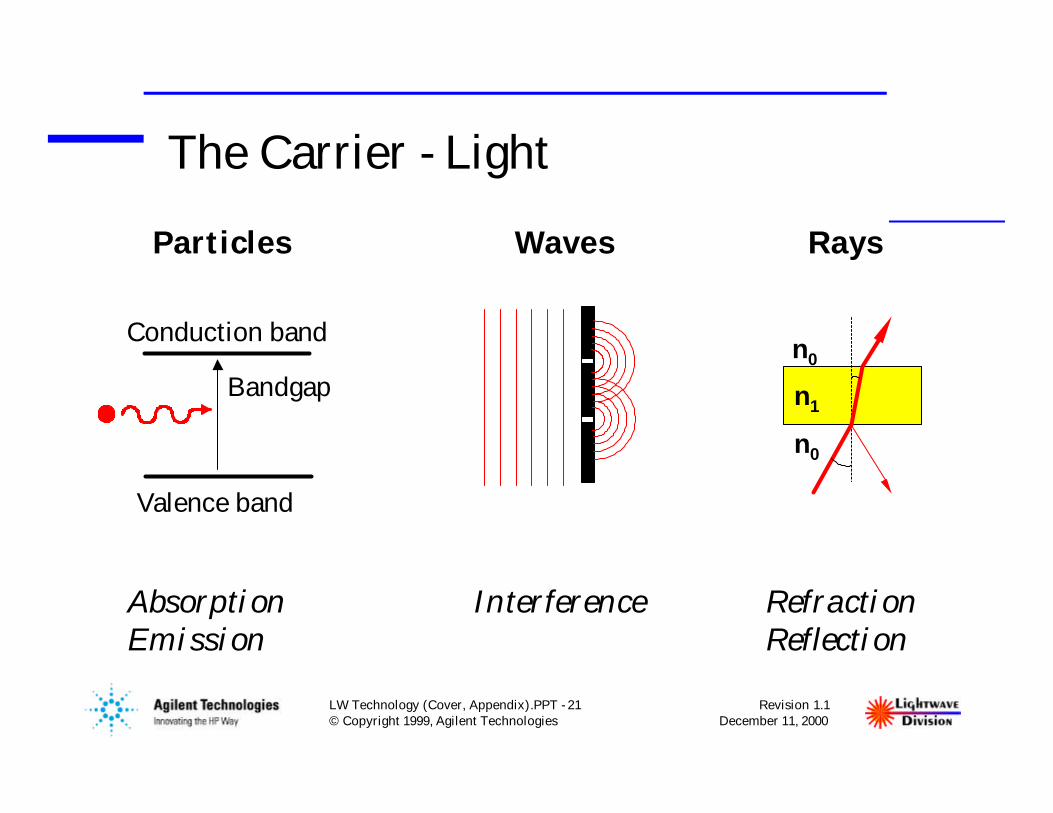
The Carrier - Light
RaysWavesParticles
AbsorptionEmission
Interference RefractionReflection
Bandgap
Conduction band
Valence band
n0
n1
n0

LW Technology (Cover, Appendix).PPT - 22© Copyright 1999, Agilent Technologies
Revision 1.1December 11, 2000
Light Properties - Wavelength
λ
Distance
FieldStrength
1000 pm (picometer) = 1 nm (nanometer) 1000 µm = 1 mm (millimeter) 1000 nm (nanometer) = 1 µm (micrometer) 1000 mm = 1 m (meter) (~40 inches)
Wavelength λ: distance to complete one sine wave

LW Technology (Cover, Appendix).PPT - 23© Copyright 1999, Agilent Technologies
Revision 1.1December 11, 2000
Electromagnetic Spectrum
Frequency
Sonic
Ultrasonic
AM Broadcast
Shortwave Radio
FM Radio/TVRadar
Infrared Light
Visible Light
Ultraviolet
X-Rays
Wavelength 1 Mm 1 km 1 m 1 mm 1 pm1 nm
1 kHz 1 MHz 1 GHz 1 THz 1 ZHz1 YHz
c = f • λ • nc: Speed of light ( 2.9979 m/µs )f: Frequencyλ: Wavelengthn: Refractive index
(vacuum: 1.0000; standard air: 1.0003; silica fiber: 1.44 to 1.48)

LW Technology (Cover, Appendix).PPT - 24© Copyright 1999, Agilent Technologies
Revision 1.1December 11, 2000
LW Transmission Bands
Near InfraredFrequency
Wavelength1.6
229
1.0 0.8 µm0.6 0.41.8 1.4
UV
(vacuum) 1.2
THz193 461
0.2
353
Longhaul Telecom
Regional Telecom
Local Area Networks850 nm
1550 nm
1310 nmCD Players780 nm
HeNe Lasers633 nm

LW Technology (Cover, Appendix).PPT - 25© Copyright 1999, Agilent Technologies
Revision 1.1December 11, 2000
Optical Power
• Power (P):– Transmitter: typ. -6 to +17 dBm (0.25 to 50 mW)– Receiver: typ. -3 to -35 dBm (500 down to 0.3 µW)– Optical Amplifier: typ. +3 to +20 dBm (2 to 100 mW)
• Laser safety– International standard: IEC 825-1– United States (FDA): 21 CFR 1040.10– Both standards consider class I safe under reasonable forseeable
conditions of operation (e.g., without using optical instruments, suchas lenses or microscopes)

LW Technology (Cover, Appendix).PPT - 26© Copyright 1999, Agilent Technologies
Revision 1.1December 11, 2000
Laser Power Limits Of Class I(for test equipment applications)
IEC 825-1 (EN 60825-1)
Wavelength Fiber / NA Limit
850 nm MM / 0.15 0.44 mW
1200 to MM / 0.15 8.9 mW1400 nm SM / 0.10 8.9 mW
1400 to SM / 0.10 10 mW4000 nm
21 CFR 1040.10
Wavelength Fiber / NA Limit
850 nm MM / 0.15 2.8 mW
1060 to MM / 0.15 4.9 mW1400 nm SM / 0.10 1.9 mW
1400 to SM / 0.10 7.842500 nm
(1984) (11/1993)

LW Technology (Cover, Appendix).PPT - 27© Copyright 1999, Agilent Technologies
Revision 1.1December 11, 2000
The Logarithmic Scale
0 dBm = 1 mW
3 dBm = 2 mW5 dBm = 3 mW10 dBm = 10 mW20 dBm = 100 mW
-3 dBm = 0.5 mW-10 dBm = 100 µW-30 dBm = 1 µW-60 dBm = 1 nW
0 dB = 1
+ 0.1 dB = 1.023 (+2.3%)+ 3 dB = 2+ 5 dB = 3+ 10 dB = 10
-3 dB = 0.5-10 dB = 0.1-20 dB = 0.01-30 dB = 0.001
dB = 10 • log10 (P1 / P0) dBm = 10 • log10 (P / 1 mW)

LW Technology (Cover, Appendix).PPT - 28© Copyright 1999, Agilent Technologies
Revision 1.1December 11, 2000
Coherence
• Coherent lightPhotons have fixed phaserelationship (laser light)
• Incoherent lightPhotons with random phase(sun, light bulb)
• Coherence length (CL)Average distance over whichphotons lose their phaserelationship
1/e
1
CL

LW Technology (Cover, Appendix).PPT - 29© Copyright 1999, Agilent Technologies
Revision 1.1December 11, 2000
Interference
• Incoherent light adds up optical power
• Coherent light adds electromagnetic fields
• Zero phase shift:constructive interference
• 180º phase shift: destructive interference
+ =
+ =

LW Technology (Cover, Appendix).PPT - 30© Copyright 1999, Agilent Technologies
Revision 1.1December 11, 2000
Reflections
• Reflections: root cause for many problemsReturn loss definition:
RL = 10 * log
Pr
Pi
P reflected
P incident

LW Technology (Cover, Appendix).PPT - 31© Copyright 1999, Agilent Technologies
Revision 1.1December 11, 2000
Polarization
y
x
z
SOP: linearhorizontal
SOP: linearvertical• Most lasers are highly polarized
• Degree of polarization (DOP):DOP = P polarized / P total
• State of polarization (SOP):describes the orientationand rotation of thepolarized light

LW Technology (Cover, Appendix).PPT - 32© Copyright 1999, Agilent Technologies
Revision 1.1December 11, 2000
Poincaré SphereGraphical representation of state of polarizationusing Stokes parameters (S1, S2, S3)
Left-handcircularpolarization(0,0,-1)
S 1 axis
S2 axis
S 3 axi
s
45 degree linearpolarization (0,1,0)
Right-handcircularpolarization(0,0,1)
Vertical linearpolarization (-1,0,0)

LW Technology (Cover, Appendix).PPT - 33© Copyright 1999, Agilent Technologies
Revision 1.1December 11, 2000
Digital Modulation
• Digital Modulation:– Extinction ratio = P1 / P0– Time-division multiplexing (TDM)– ~1.5 Mb/s to 10 Gb/s
• Bit Error Rate (BER):– BER = N incorrect / N total
– Standards: 1E-9 to 1E-12– Lightwave systems: down to 1E-15
2Channel
4 131
P0
t
P1
0

LW Technology (Cover, Appendix).PPT - 34© Copyright 1999, Agilent Technologies
Revision 1.1December 11, 2000
Analog Modulation
• AM modulation around Pavg– Mostly for video signals– Modulation index ~ 2%– Frequency-domain multiplexing– 50 to 500 MHz
0
Pavg
tChannel 1
Channel 2
…
Channel N
RFΣ Analog Laser
Transmitter
RF

LW Technology (Cover, Appendix).PPT - 35© Copyright 1999, Agilent Technologies
Revision 1.1December 11, 2000
Review Questions
1. What are the three key parameters of light?
2. How much power is +13 dBm? -27 dBm?How much loss is 6 dB? 15 dB?
3. What is TDM?
4. Where on the Poincaré sphere is the horizontallinear polarization state?

Revision 1.1December 11, 2000
LW Technology (Cover, Appendix).PPT - 36© Copyright 1999, Agilent Technologies
Standards
LW Technology

LW Technology (Cover, Appendix).PPT - 37© Copyright 1999, Agilent Technologies
Revision 1.1December 11, 2000
Lightwave Standards Evolution
Basics - Measurement of power and wavelength
Point-to-point custom solutions
Agreement on parameter characteristics
Multi-vendor market emerges
Interoperability - still elusive

LW Technology (Cover, Appendix).PPT - 38© Copyright 1999, Agilent Technologies
Revision 1.1December 11, 2000
Network Model
FUTUREFORMAT
ATM /SONET
LEGACYSWITCH
ATM /SONET
FUTUREFORMAT
ATM /SONET
LEGACYSWITCH
ATM /SONET
X-C
X-C
X-CRing
R
DATA MULTIMEDIA
VIDEO
IMAGEVOICE
LAN
OPTICALACCESS
WDM NETWORK ELEMENTS
R
X-C WDM X-Connect
WDM Routing Star
WDM Add/Drop Mux
X-C X-C
X-CX-C
Con
figu
rabl
eO
ptic
al, W
DM
Lay
ers
Ele
ctro
nic
Sw
itch
ing
Lay
ers
App
lica
tion
sL
ayer
Local ExchangeNetwork
Long DistanceNetwork
Private Network(with Optical Access)(with Optical Access)

LW Technology (Cover, Appendix).PPT - 39© Copyright 1999, Agilent Technologies
Revision 1.1December 11, 2000
Key Standards• Telecom Standards
– Plesiochronous Digital Hierarchy (PDH)– Synchronous Optical Network (SONET) /
Synchronous Digital Hierarchy (SDH)– Asynchronous Transfer Mode (ATM)– Dense Wavelength-Division Multiplexing (DWDM)
• Datacom Standards– Ethernet, Fast Ethernet (coax or twisted air cable)– Gigabit-Ethernet (IEEE 802.3z)– Fiber Distributed Data Interface (FDDI)– Fibre Channel (FC-PH)– Internet Protocol (IP)

LW Technology (Cover, Appendix).PPT - 40© Copyright 1999, Agilent Technologies
Revision 1.1December 11, 2000
PDH Networks
• Developed in the early 1970’s– Still many systems in place, especially for low speed traffic
• Multiplexes digital voice circuits (64 kb/s)– North America: DS1 (1.5 Mb/s) to DS4 (139 Mb/s)
Europe: E1 (2 Mb/s) to E4 (139 Mb/s)Japan: 2 to 98 Mb/s
• Drawbacks– Not perfectly synchronized: extra bits needed– Difficult to add/drop low speed stream from high-speed stream– No standard on line interfaces & coding (interoperability!)– Seconds to minutes to restoration time after a failure

LW Technology (Cover, Appendix).PPT - 41© Copyright 1999, Agilent Technologies
Revision 1.1December 11, 2000
SONET / SDH• THE standard for new telecom networks:
– North America: SONET version– International: SDH version– Optimized for voice traffic– Virtual container technology can carry many different
traffic types & speeds
• Definitions include:– Optical requirements– Modulation and BER– Functional layer (e.g., frames)– Protection and restoration– Network management

LW Technology (Cover, Appendix).PPT - 42© Copyright 1999, Agilent Technologies
Revision 1.1December 11, 2000
Typical Ring Structures
• Two pairs of fibers between nodes– One fiber for each direction between nodes– One restoration fiber for each direction
• Network cut (single fault)– Traffic rerouted in opposite direction– Restoration within 0.5 sec– 100% protection!
• Nodes types– Add/drop multiplexers (ADM)– Digital cross-connects (DTE)
LW Technology (Cover, Appendix).PPT - 43© Copyright 1999, Agilent Technologies
Revision 1.1December 11, 2000
DWDM Standards
• ITU Draft Recommendation G.692:“Optical Interfaces for Multichannel Systemswith Optical Amplifiers”
– Specifies interfaces for the purpose of providing future transversecompatibility among such systems.
– Defines the wavelength grid for multichannel systems.– Currently on hold pending resolution of intellectual property issues.– Large backlog of proposed changes/additions.

LW Technology (Cover, Appendix).PPT - 44© Copyright 1999, Agilent Technologies
Revision 1.1December 11, 2000
The Frequency Grid From G.692
196.0 195.5 195.0 194.5 194.0 193.5 193.0 192.5 192.0 191.5 191.0F (THz)
156515601545154015351530 1550λ (nm)
1555
• Channels anchored at a 193.1-THz reference
• 100-GHz spacing with no defined lower or upper bound.
The U.S. (TIA) will formally propose a change to 50-GHz spacing.

LW Technology (Cover, Appendix).PPT - 45© Copyright 1999, Agilent Technologies
Revision 1.1December 11, 2000
Asynchronous Transfer Mode (ATM)
• High performance data transfer standard– Uniform cell: 5 header bytes, 48 data bytes– Simple and efficient cell switching– Optimizes use of available network capacity
• Quality of Service (QoS)– Bandwidth and delay guarantees– Admission control to satisfy QoS
• Compatibility with installed networks– Can run over PDH or SONET/SDH systems

LW Technology (Cover, Appendix).PPT - 46© Copyright 1999, Agilent Technologies
Revision 1.1December 11, 2000
Internet Protocol (IP)
• WAN / MAN / LAN protocol for data– Originally designed for data (e-mail, file transfer)– Voice & video applications under development
• Layered design– Key contribution to widespread deployment– Can be easily adapted to new technologies– Higher layers can run over other data networks
as long as they provide compatible services
• Point-to-Point protocol (PPP)– Common data link layer to connect PCs to LANs
or to the internet via phone lines (e.g., home PCwith modem)
7 - Application6 - Presentation5 - Session4 - Transport3 - Network2 - Data link1 - Physical

LW Technology (Cover, Appendix).PPT - 47© Copyright 1999, Agilent Technologies
Revision 1.1December 11, 2000
Common Transmission Speeds• SONET/SDH rates:
– OC-3, STM-1: 155.52 Mb/s– OC-12, STM-4: 622.08 Mb/s– OC-48, STM-16: 2488.32 Mb/s– OC-192, STM-64: 9953.28 Mb/s
• Datacom rates:– FDDI: 125 (100) Mb/s– FireWire: 100 - 800 Mb/s– Fibre Channel: 266 - 1063 Mb/s– Ethernet: 10 or 100 Mb/s– G-Ethernet: 1250 Mb/s
• PDH:North America:– DS1: 1.544 Mb/s– DS2: 6.312 Mb/s– DS3: 44.736 Mb/s– DS4: 139.264 Mb/s
Europe:– E1 2.048 Mb/s– E2: 8.448 Mb/s– E3: 34.368 Mb/s– E4: 139.264 Mb/s

LW Technology (Cover, Appendix).PPT - 48© Copyright 1999, Agilent Technologies
Revision 1.1December 11, 2000
Review Questions
1. Why do most operators like SONET/SDH ?
2. What is the advantage of a layered design?
4. What are the key properties of DWDM?

Revision 1.1December 11, 2000
LW Technology (Cover, Appendix).PPT - 49© Copyright 1999, Agilent Technologies
Fibers, Cables,Splices & Connectors
LW Technology

LW Technology (Cover, Appendix).PPT - 50© Copyright 1999, Agilent Technologies
Revision 1.1December 11, 2000
Basic Step-Index (SI) Fiber Design
RefractiveIndex (n)
Diameter (r)
Cladding
Primary coating(e.g., soft plastic)
Core
1.4801.460
SiO 2 Glass
• Most common designs: 100/140 or 200/280 µm• Plastic optical fiber (POF): 0.1 - 3 mm ∅, core 80 to 99%
140 µm
100 µm

LW Technology (Cover, Appendix).PPT - 51© Copyright 1999, Agilent Technologies
Revision 1.1December 11, 2000
Numerical Aperture (NA)
Acceptance / Emission Cone
NA = sin θ = n2core - n2
cladding
θ

LW Technology (Cover, Appendix).PPT - 52© Copyright 1999, Agilent Technologies
Revision 1.1December 11, 2000
Attenuation In Silica Fibers
900 1100 1300 1500 1700
0.5
1.0
1.5
2.0
2.5
OH Absorption
Att
enua
tion
(dB
/km
)
Wavelength (nm)
“Optical Windows”
2 3
1
Main cause of attenuation: Rayleigh scattering in the fiber core

LW Technology (Cover, Appendix).PPT - 53© Copyright 1999, Agilent Technologies
Revision 1.1December 11, 2000
Step-Index Multimode (MM)Dispersion
Pulse broadening due to multi-pathtransmission.
Bitrate x Distance product is severely limited!
100/140 µm Silica Fiber: ~ 20 Mb/s • km 0.8/1.0 mm Plastic Optical Fiber: ~ 5 Mb/s • km

LW Technology (Cover, Appendix).PPT - 54© Copyright 1999, Agilent Technologies
Revision 1.1December 11, 2000
Gradient-Index (GI) Fiber• Doping profile designed to minimize “race” conditions
(“outer” modes travel faster due to lower refractive index!)• Most common designs: 62.5/125 or 50/125 µm, NA ~ 0.2• Bitrate x Distance product: ~ 1 Gb/s • km
n
r
1.475
1.460

LW Technology (Cover, Appendix).PPT - 55© Copyright 1999, Agilent Technologies
Revision 1.1December 11, 2000
Single-Mode Fiber (SMF)
• Step-Index type with very small core• Most common design: 9/125 µm or 10/125 µm, NA ~ 0.1• Bitrate x Distance product: up to 1000 Gb/s • km
(limited by CD and PMD - see next slides)
n
r
1.4651.460

LW Technology (Cover, Appendix).PPT - 56© Copyright 1999, Agilent Technologies
Revision 1.1December 11, 2000
Chromatic Dispersion (CD)• Light sources are NOT monochromatic
(linewidth of source, chirp effects, modulation sidebands)
• Different wavelengths travel at slightly different speeds(this effect is called “Chromatic Dispersion”)
• Chromatic dispersion causes pulse broadening(problem at high bit rates over long distances)
• Standard single-mode fiber:– 1300 nm window has lowest CD– 1550 nm lowest loss

LW Technology (Cover, Appendix).PPT - 57© Copyright 1999, Agilent Technologies
Revision 1.1December 11, 2000
Dispersion-Shifted Fiber (DSF)• Additional doping to shift zero dispersion to 1550 nm
– Now 1550 nm lowest loss AND lowest dispersion– Can cause nonlinear effects in DWDM systems (see later)
• Non-Zero Dispersion Shifted Fiber (NZDSF)– Low dispersion around 1550 nm and low nonlinear effects– Requires chromatic dispersion compensators on long distances
0
20
C. D
ispe
rsio
n ps
/(nm
• k
m)
-101600 1700140013001200 1500
10
SMF NZDSFDSF

LW Technology (Cover, Appendix).PPT - 58© Copyright 1999, Agilent Technologies
Revision 1.1December 11, 2000
Polarization Mode Dispersion (PMD)• Single-mode fiber actually transmits two modes
– Modes have opposite states of polarization– Severe limitation at 10 Gb/s over distances > 50 km
• Power is randomly coupled between the two modes– PMD of a link fluctuates significantly over time
• Components can exhibit PMD as well– mostly constant PMD– manufacturers trying to
minimize it by design

LW Technology (Cover, Appendix).PPT - 59© Copyright 1999, Agilent Technologies
Revision 1.1December 11, 2000
Cable Designs
• Mechanical design:– Indoor, outdoor, submarine– Local or national building and construction
codes may apply
• Electrical designs:– No metal or electrical wires at all– Power wires (supply for remote amplifiers
or regenerators)
Optical fibers
Tube
Strain relief(e.g., Kevlar)
Innerjacket
Sheath
Outerjacket

LW Technology (Cover, Appendix).PPT - 60© Copyright 1999, Agilent Technologies
Revision 1.1December 11, 2000
Issues Of Connecting Fibers
Offset Angular Misalignment
Separation
Core Eccentricity Core Ellipticity Reflections &Interference

LW Technology (Cover, Appendix).PPT - 61© Copyright 1999, Agilent Technologies
Revision 1.1December 11, 2000
Medium insertion loss:
Worst return loss:< 14 dB (Fresnel)
Common multimode fiber connector
Air Gap
typ. 0.5 dBLowest insertion loss:
< 0.25 dB
Good return loss:
Common single-mode fiber connector
Physical Contact(PC)
> 40 dB
Highest insertion loss:
Best return loss:
Cable TV, highperformance systems
Angled PhysicalContact (APC)
0.4 to 0.9 dB
> 60 dB
Connector Types
8º

LW Technology (Cover, Appendix).PPT - 62© Copyright 1999, Agilent Technologies
Revision 1.1December 11, 2000
Connector Technology
• Ultra-high precision– Optical axis aligned to better than ±1
µm (single-mode)– Physical contact of the glass end
surfaces necessary
• Connector cleanliness isparamount– special cleaning and inspection
required
Sleeve
Ferrule
FiberKey

LW Technology (Cover, Appendix).PPT - 63© Copyright 1999, Agilent Technologies
Revision 1.1December 11, 2000
Connector Brands
Photo courtesyof: Diamond SA

LW Technology (Cover, Appendix).PPT - 64© Copyright 1999, Agilent Technologies
Revision 1.1December 11, 2000
Connector Inspection
Don’t stare intothe laser beam
(with your remaining eye)Inspection Tool

LW Technology (Cover, Appendix).PPT - 65© Copyright 1999, Agilent Technologies
Revision 1.1December 11, 2000
Connector Care
New Connector Damaged Connector

LW Technology (Cover, Appendix).PPT - 66© Copyright 1999, Agilent Technologies
Revision 1.1December 11, 2000
Connector Cleaning
Pure Cotton Swabs
Isopropyl Alcohol
Filtered Air
Variety of cleaningmethods in use today
Example:Clean connector tips withIsopropyl (96% medical alcohol)using adhesive free cotton swabs
Immediately dry it with dust-free,non residue compressed air

LW Technology (Cover, Appendix).PPT - 67© Copyright 1999, Agilent Technologies
Revision 1.1December 11, 2000
Splices
• Fusion Splices– Most common permanent fiber connection– Very high performance and reliability– Insertion loss 0.01 to 0.1 dB, no reflection– Automated splicing tool costs $10k to $50k
• Mechanical Splices– Permanent and non-permanent types– Insertion loss 0.1 to 0.5 dB– Index-matching liquid used to minimize loss & reflections– Epoxy or UV hardened elastomer based– Less expensive tools ($100 to $1,000) required
Protective sleeve
Splice

LW Technology (Cover, Appendix).PPT - 68© Copyright 1999, Agilent Technologies
Revision 1.1December 11, 2000
Review Questions
1. What are commonly used fiber types?
2. What is dispersion and what can cause it?
3. What are good connector care habits?