Embed Size (px)
Citation preview

JOURNAL OF LIGHTWAVE TECHNOLOGY, VOL. 33, NO. 14, JULY 15, 2015 3091
A High Spectral Efficiency Coherent MicrowavePhotonic Link Employing Both Amplitude and Phase
Modulation With Digital Phase Noise CancellationXiang Chen, Student Member, IEEE, and Jianping Yao, Fellow, IEEE, Fellow, OSA
Abstract—A high spectral efficiency coherent microwave pho-tonic link (MPL) supporting amplitude and phase modulationincorporating a digital phase noise cancellation is proposed and ex-perimentally demonstrated. At the transmitter, a continuous-wavelight wave is amplitude- and phase-modulated by two microwavevector signals carried by a microwave carrier at an identical fre-quency. The modulated optical signal is polarization multiplexedwith an unmodulated optical carrier and transmitted over a lengthof a single-mode fiber (SMF). At the receiver, the optical signal isdetected coherently by a coherent receiver to which a local oscil-lator (LO) laser source is also applied. Through advanced digitalsignal processing, the microwave vector signals are recovered, andthe phase noise introduced by both the transmitter laser sourceand LO laser source is cancelled. An experiment is performed.The transmission of a 2.5-Gb/s 16-QAM and a 1.25-Gb/s QPSKmicrowave vector signals both at 2.5 GHz over a 25-km SMF isimplemented. The total bit rate of the MPL is 3.75 Gb/s. Thetransmission performance of the MPL in terms of error vectormagnitudes and bit error rates is evaluated.
Index Terms—Digital signal processing (DSP), high spectralefficiency, laser phase noise, microwave photonic link (MPL),optical coherent detection, phase noise cancellation (PNC).
I. INTRODUCTION
THE transmission of microwave signals over an opticalfiber, or radio over fiber, is considered a potential solu-
tion for next generation broadband wireless access networkssince a radio over fiber link or microwave photonic link (MPL)presents several advantages over a conventional copper coax-ial analog link, including a much wider bandwidth, lower linkloss, and immunity to electromagnetic interferences [1]–[3]. Ina conventional MPL, intensity-modulation and direct-detection(IM/DD) is usually employed which has an advantage of imple-mentation simplicity. However, compared with a coherent MPLwhich can detect both intensity- and phase-modulated signals,an MPL employing IM/DD has a much lower spectral efficiency,since direct detection can only detect an intensity-modulatedsignal. For broadband wireless access networks, high spectral
Manuscript received December 15, 2014; revised March 5, 2015 and March30, 2015; accepted March 31, 2015. Date of publication April 1, 2015; date ofcurrent version June 3, 2015. This work was supported by the Natural Sciencesand Engineering Research Council of Canada.
The authors are with the Microwave Photonics Research Laboratory, Schoolof Electrical Engineering and Computer Science, University of Ottawa, OttawaON K1N 6N5, Canada (e-mail: [email protected]).
Color versions of one or more of the figures in this paper are available onlineat http://ieeexplore.ieee.org.
Digital Object Identifier 10.1109/JLT.2015.2419456
efficiency is always needed. In addition, a coherent MPL has areceive sensitivity of about 20 dB higher than that of an IM/DDMPL, which provides an added advantage to a coherent MPL[4].
Numerous solutions have been proposed to implement coher-ent MPLs recently [5]–[12]. In [5], [6], a phase-modulationand coherent-detection (PM/CD) MPL was proposed. Thephase noise was cancelled through the use of a digital phaselocked loop. In [7], [8], two intensity-modulation and coherent-detection (IM/CD) MPLs were proposed in which the phasenoise was cancelled by digital signal processing (DSP)-basedenvelope detection or DSP-based coherent detection. The limi-tation of the schemes is that only the phase [5], [6] or amplitude[7], [8] information on the optical carrier can be detected, thusthe spectral efficiency is still limited. To increase the spectralefficiency, in [9] we proposed a photonic approach to modu-lating two microwave vector signals, which have the same RFcenter frequency, on a single optical carrier employing opticalIQ modulation and coherent detection. The spectral efficiencyis significantly increased, but the phase noise introduced bythe transmitter laser source was not cancelled, which will de-grade the transmission performance. A simple way to avoid thephase noise from the local oscillator (LO) laser source is to usean additional fiber to deliver an LO signal from the transmit-ter to the receiver [10]–[12]. But the system cost is increased.In addition, because of the link loss, the LO signal needs tobe amplified at the receiver by an optical amplifier to satisfy thepower level needed for coherent detection, which may introducean additional noise due to the amplified spontaneous emissionnoise from the optical amplifier.
In this paper, we propose and experimentally demonstrate ahigh spectral efficiency coherent MPL supporting amplitude andphase modulation with digital phase noise cancellation (PNC)without using an additional fiber link. At the transmitter, a lightwave from a laser source is split into two channels. In the up-per channel, the light wave is first intensity modulated by a 16quadrature amplitude modulation (16-QAM) microwave vec-tor signal and then phase modulated by a quadrature phaseshift keying (QPSK) microwave vector signal. The light wavein the lower channel is not modulated. Then, the two lightwaves from the two channels are polarization multiplexed atthe polarization beam splitter (PBS) and sent to a receiver overa single mode fiber (SMF). At the receiver, the two orthogo-nally polarized light waves are demultiplexed by a second PBSand then detected by a coherent optical receiver, to generatefour currents which contain the information of the 16-QAM

3092 JOURNAL OF LIGHTWAVE TECHNOLOGY, VOL. 33, NO. 14, JULY 15, 2015
Fig. 1. Schematic of the proposed coherent MWP link with a DSP-based PNC module. ADC: analog-to-digital converter, OC: optical coupler, PC: polarizationcontroller, CW laser: continuous- wave laser, balanced PD: balanced photodetector, MZM: Mach–Zehnder modulator, QPSK: quadrature phase shift keying, PM:phase modulator, PBS: polarization beam splitter, PR: polarization rotator, 16-QAM: 16 quadrature amplitude modulation, SMF: single mode fiber.
and QPSK signals. An algorithm is developed to recover the16-QAM and the QPSK microwave vector signals while can-celling the phase noise introduced by both the transmitter lasersource and LO laser source. The proposed technique is validatedby an experiment. The transmission of a 2.5-Gb/s 16-QAM anda 1.25-Gb/s QPSK microwave vector signals over a 25-km SMFis demonstrated. The transmission performance is evaluated bymeasuring the error vector magnitudes (EVMs). The EVM of therecovered 16-QAM microwave vector signal can reach 8.05%and that of the recovered QPSK microwave vector signal canreach 8.23%. The bit error rates (BERs) calculated from themeasured EVMs are also evaluated. Compared with coherent-detection MPLs based only on phase [5], [6], or amplitude mod-ulation [7], [8], the spectral efficiency of the proposed scheme issignificantly increased while maintaining the same transmissionperformance.
II. PRINCIPLE OF OPERATION
Fig. 1 shows the schematic diagram of the proposed highspectral efficiency coherent MPL. At the transmitter, a lightwave from a CW laser source is split by an optical coupler(OC) (95% and 5% optical powers for Channel 1 and Chan-nel 2, respectively) into two channels. In Channel 1, the lightwave is amplitude- and phase-modulated by a 16-QAM anda QPSK microwave vector signal, respectively, at a chirp-freesingle-electrode Mach–Zehnder modulator (MZM) and a phasemodulator (PM) while the light wave in Channel 2 is not mod-ulated. The two light waves from the two channels are thenpolarization multiplexed at a PBS (PBS1) and sent to a receivervia a 25-km SMF. At the receiver, a second PBS (PBS2) whichis incorporated in the polarization- and phase-diversity coherentoptical receiver (Discovery Semiconductors DP-QPSK 40/100Gb/s Coherent Receiver) is used to demultiplex the two orthog-onally polarized light waves (Channel X and Channel Y), whichare then sent to two 90o optical hybrids inside the coherent op-tical receiver. An LO signal from a second laser source is splitinto two channels and also sent to the two hybrids. After bal-anced detection in the coherent optical receiver, four channels(XI, XQ, YI and YQ) of signals corresponding to the in-phaseand quadrature (IQ) components of the two orthogonally polar-ized signals from the PBS2 are obtained, which are then sentto a DSP-based PNC module. An algorithm is developed torecover the 16-QAM microwave vector signal and the QPSK
microwave vector signal while cancelling the phase noise intro-duced by both the transmitter and LO laser sources.
At the transmitter, for Channel 1, the MZM is biased at thequadrature point and 16-QAM microwave vector signal is ap-plied to the MZM via the RF port. The optical field at the outputof the MZM is given by
E0(t) =√
2Ps1Ls1 cos[πSRF −16QAM (t)
2VπIM+
π
4
]
× exp{j[ωct + ϕc1(t)]} (1)
where Ps1 is the optical power at the input of Channel 1, ωc isthe angular frequency of the light wave, SRF −16QAM (t)is themicrowave vector signal applied to the MZM, the modulationformat is 16-QAM, ϕc1(t)is the phase term of the transmitterlaser source for Channel 1, VπIM is the half-wave voltage of theMZM, and Ls1 is the link loss between the OC and PBS1 forChannel 1.
Then, the amplitude-modulated optical signal is phase-modulated by a QPSK microwave vector signal. The opticalfield at the output of the PM is given by
E1(t) =√
2Ps1Ls1 cos[πSRF −16QAM (t)
2VπIM+
π
4
]
× exp{
j
[ωct + ϕc1(t) +
πSRF −QP SK (t)VπP M
]}(2)
where SRF −QP SK (t) is the QPSK microwave vector signalapplied to the PM, the modulation format is QPSK and VπP M
is the half-wave voltage of the PM.For Channel 2, the light wave is not modulated. The optical
field at the output of Channel 2 is given by
E2 (t) =√
2Ps2Ls2 exp {j [ωct + ϕc2(t)]} (3)
where Ps2 is the optical power at the input of Channel 2, ϕc2(t)isthe phase term of the transmitter laser source for Channel 2, andLs2 is the link loss between the OC and PBS1 for Channel2. Note, ϕc1(t) and ϕc2(t) are different, since the optical sig-nals from the transmitter laser source are split by an OC andtransmitted through two fibers.
Then, the two light waves from the two channels are po-larization multiplexed at PBS1 and transmitted over the SMF.At the receiver, the two orthogonally polarized light wavesare demultiplexed by PBS2 into two channels (Channel X andChannel Y).

CHEN AND YAO: HIGH SPECTRAL EFFICIENCY COHERENT MICROWAVE PHOTONIC LINK EMPLOYING BOTH AMPLITUDE 3093
The optical fields at the outputs of PBS2 for Channel X andChannel Y are given by
Ex (t) = E1 (t) (4)
Ey (t) = E2 (t) . (5)
On the other hand, the optical field at the output of the LOlaser source can be written as
ELO (t) =√
2PLO exp {j [ωLO t + ϕLO (t)]} . (6)
Through tuning PC6, with the help of the polarization rotatorin Fig. 1, the light wave from the LO laser source is co-polarizedwith the other optical signals at the inputs of the two 90o opticalhybrids. At the outputs of the two 90o optical hybrids, eightoptical fields are obtained, given by
[Ea (t) Eb (t) Ec (t) Ed (t)
Ee (t) Ef (t) Eg (t) Eh (t)
]
=√
Lh
[√Lf Ex (t) ELO (t) ejϕx /
√2
√Lf Ey (t) ELO (t) ejϕy /
√2
]
·(
1 1 1 1
1 ejπ ejπ/2 e−jπ/2
)
(7)
where Lh is the link loss caused by the two 90° optical hybrids,Lf is the link loss caused by the SMF, and ϕx ,ϕy are the phaseterms arising from the polarization mismatch between the signaland the light wave from the LO laser source.
By applying (Ea,Eb ), (Ec,Ed ), (Ee,Ef ), (Eg ,Eh ) to fourbalanced PDs which are terminated with 50-Ω resistors, fouroutput photocurrents are obtained, which are given by
IP D1 = 2RLh
√2Ps1PLO Lf Ls1
× cos[πSRF −16QAM (t) /2VπIM +
π
4
]
× cos [Δωt + ϕ1 (t) − ϕx + πSRF −QP SK (t)/VπP M]
(8)
IP D2 = 2RLh
√2Ps1PLO Lf Ls1
× cos[πSRF −16QAM (t) /2VπIM +
π
4
]
× sin [Δωt + ϕ1 (t) − ϕx + πSRF −QP SK (t)/VπP M]
(9)
IP D3 = 2RLh
√2Ps2PLO Lf Ls2 cos [Δωt + ϕ2(t) − ϕy ] (10)
IP D4 = 2RLh
√2Ps2PLO Lf Ls2 sin [Δωt + ϕ2(t) − ϕy ] (11)
with
Δω = ωc − ωLO ,
ϕ1(t) = ϕc1(t) − ϕLO (t), ϕ2(t) = ϕc2(t) − ϕLO (t)
where Δω is the frequency difference between the transmitterlaser source and the LO laser source, ϕ1(t), ϕ2(t)are the phasenoise introduced by the transmitter laser source and the LOlaser source. Before we explain the method to recover the 16-QAM microwave vector signal and the QPSK microwave vector
signal, it is important to investigate how the phase noise affectsthe 16-QAM microwave vector signal and the QPSK microwavevector signal.
First, an ideal situation is considered, where Δω = 0 and nosignal is sent to the PM (SRF −QP SK (t) = 0). Then, (8) can berewritten as
IP D1 = 2RLh
√2Ps1PLO Lf Ls1
× cos [πSRF −16QAM (t) /2VπIM + π/4]
× cos [ϕ1 (t) − ϕx ] . (12)
From (12), it can be seen that the phase noise ϕ1(t) is con-verted to an amplitude noise given by cos (ϕ1(t) − ϕx) at theoutput of the coherent receiver.
If Δω = 0 and no signal is sent to the MZM, (8) can beexpressed as
IP D1 = 2RLh
√2Ps1PLO Lf Ls1 cos (π/4)
×{
cos [ϕ1(t) − ϕx ] cos [πSRF −QP SK (t) /VπP M ]
− sin [ϕ1 (t) − ϕx ] sin [πSRF −QP SK (t) /VπP M ]
}
.
(13)
As can be seen, the phase noise ϕ1(t) is also converted to anamplitude noise given by sin (ϕ1(t) − ϕx).
Then, a more realistic situation is considered where Δω �= 0and both the intensity and phase of the optical light are modu-lated. Equations (8) and (9) can be further expanded as
IP D1 = 2RLh
√2Ps1PLO Lf Ls1
× [(A × C − A × D) − (B × C − B × D)] (14)
IP D2 = 2RLh
√2Ps1PLO Lf Ls1
× [(A × E + A × F ) − (B × E + B × F )] (15)
with
A = cos [πSRF −16QAM (t) /2VπIM ] cos (π/4)
B = sin [πSRF −16QAM (t) /2VπIM ] sin (π/4)
C = cos [Δωt + ϕ1 (t) − ϕx ] cos [πSRF −QP SK (t) /VπP M ]
D = sin [Δωt + ϕ1 (t) − ϕx ] sin [πSRF −QP SK (t) /VπP M ]
E = cos [Δωt + ϕ1 (t) − ϕx ] sin [πSRF −QP SK (t) /VπP M ]
F = sin [Δωt + ϕ1 (t) − ϕx ] cos [πSRF −QP SK (t) /VπP M ] .
In (14) and (15), if we assume that both the QPSK and the16-QAM microwave vector signals are small signals, then A×Dand A×E represent the detected QPSK microwave vector signalsat the outputs of the coherent receiver (IP D1 and IP D2). Thefrequencies of the detected QPSK microwave vector signals areup converted because of the frequency difference between thetransmitter laser source and LO laser source. And B×C, B×Frepresent the detected 16-QAM microwave vector signals andtheir frequencies are also up converted due to the same reason. Ifthe center frequencies and bandwidths of the QPSK microwavevector signal and the 16-QAM microwave vector signal are

3094 JOURNAL OF LIGHTWAVE TECHNOLOGY, VOL. 33, NO. 14, JULY 15, 2015
identical, for each output of the coherent receiver (IP D1 andIP D2), the spectra of the detected 16-QAM signal and the de-tected QPSK signal are completely overlapped. In addition, boththe detected QPSK and 16-QAM microwave vector signals areaffected by the phase noise introduced by both the transmitterlaser source and LO laser source. Apparently, it is impossibleto recover and demodulate the two microwave vector signalsdirectly from the outputs of the coherent receiver. To demodu-late the 16-QAM microwave vector signal and the QPSK mi-crowave vector signal, DSP algorithms are employed to cancelthe phase noise, eliminate the frequency shift and recover thesignals from the overlapped spectra.
First, the four signals,IP D1 ,IP D2 , IP D3 and IP D4are sepa-rately sampled and digitized by four ADCs. Then, the DSP al-gorithm is employed [8]. By summing the squared magnitudesof IPD1 and IPD2 , we can obtain
I1 = I2P D1 + I2
P D2
= 4R2L2hLf Ps1PLO Ls1
×{1 − sin [πSRF −16QAM (t) /VπIM ]}≈ 4R2L2
hLf Ps1PLO Ls1 {1 − [πSRF −16QAM (t) /VπIM ] }.(16)
As can be seen, the QPSK microwave vector signal is notpresent in the expression and the phase noise is cancelled, thusa recovery of the 16-QAM microwave vector signal free fromphase noise is realized.
Also, through DSP, we can obtain (17) as shown at the bottomof the page.
In (17), the maximum frequency of ϕ (t)is determined by thelinewidth of the transmitter laser source. So, if the lower fre-quency of the QPSK microwave vector signal is higher than themaximum frequency of ϕ (t), the QPSK microwave vector sig-nal can be simply selected by a digital bandpass filter. The signalat the output of the digital band-pass filter is then expressed as
I2 ≈ πSRF −QP SK (t)VπP M
. (18)
Similarly, the 16-QAM microwave vector signal is not presentin the expression and the phase noise is cancelled, thus a recov-ery of the QPSK microwave vector signal free from phase noiseis also realized.
III. EXPERIMENTAL DETAILS
An experiment based on the setup shown in Fig. 1 is per-formed. A tunable laser source (TLS) operating at 1550.57 nmwith a linewidth of about 100 kHz and an output power of 16dBm is utilized as the transmitter laser source. The light wavefrom the TLS is split into two channels by an OC with a splittingratio of 95:5 (95% optical power for Channel 1 and 5% opticalpower for Channel 2). In Channel 1, the light wave is sent viaa polarization controller (PC1) to a chirp-free single-electrodeMZM (JDS-Uniphase) that is biased at the quadrature point, andis modulated by a 16-QAM microwave vector signal. Then, theamplitude-modulated light wave is sent to a PM (JDS-Uniphase)via a second PC (PC2), and is phase-modulated by a QPSK mi-crowave vector signal. The optical signal at the output of thePM is then sent to PBS1 via PC3. The polarization extinctionratio of PBS1 is 20 dB. Both the 16-QAM microwave vectorsignal and the QPSK microwave vector signal are generated byan arbitrary waveform generator (Tektronix AWG7102) with acarrier frequency at 2.5 GHz. The symbol rate for each of thedigital modulated microwave signals is 625 MSymbol/s, or thebit rate for the 16-QAM microwave vector signal is 2.5 Gb/sand for the QPSK microwave vector signal is 1.25 Gb/s, and thetotal bit rate for the whole system is 3.75 Gb/s. The MZM has abandwidth of 10 GHz, a half-wave voltage of about 5.5 V and ainsertion loss of 4.5 dB, and the PM has a bandwidth of 20 GHz,a half-wave voltage of 5 V and a insertion loss of 4.5 dB.
In Channel 2, the light wave is not modulated, which is sent toPBS1 via PC4. PC3 and PC4 are used to make the polarizationdirections of the two signals align with the two principal axesof PBS1, thus the two light waves are polarization multiplexed,which are transmitted over a 25-km SMF and sent to a coher-ent receiver (Discovery Semiconductors DP-QPSK 40/100 Gb/sCoherent Receiver Lab Buddy) via PC5. Through tuning PC5,the two polarization multiplexed light waves can be demulti-plexed by PBS2, which is inside the coherent receiver (Here,PC5 can be replaced by a dynamic polarization controller in apractical system [13].). On the other hand, a second TLS (Yoko-gawa AQ2201) operating at 1550.619 nm with a linewidth ofabout 1 MHz and an output power of 9.3 dBm is used as the LOlaser source. The wavelength difference between the transmitterlaser source and the LO laser source is 0.048 nm, correspondingto a beat frequency of about 6 GHz. The light wave from theLO laser source is sent to the LO port of the coherent receiverthrough PC6. A Digital Storage Oscilloscope (Agilent DSO-X
I2 = atan[(IP D2 × IP D3 − IP D1 × IP D4)(IP D1 × IP D3 + IP D2 × IP D4)
]
= atan{
sin [πSRF −QP SK (t) /VπP M + ϕc1 (t) − ϕc2 (t) − ϕx + ϕy ]cos [πSRF −QP SK (t) /VπP M + ϕc1 (t) − ϕc2 (t) − ϕx + ϕy ]
}
= πSRF −QP SK (t) /VπP M + ϕ (t) (17)
with
ϕ (t) = ϕc1 (t) − ϕc2 (t) − ϕx + ϕy .
CHEN AND YAO: HIGH SPECTRAL EFFICIENCY COHERENT MICROWAVE PHOTONIC LINK EMPLOYING BOTH AMPLITUDE 3095
Fig. 2. Spectrum of the signals at the first output port of the coherent receiver(IPD1 ).
Fig. 3. Spectrum of the signal at the third output port of the coherent receiver(IPD3 ).
93204A) is employed to perform the analog-to-digital conver-sion at a sampling rate of 40 GSa/s. The sampled signals (IP D1 ,IP D2 , IP D3 and IP D4) are processed off-line in a computerwith the proposed DSP algorithms developed to recover the 16-QAM and the QPSK microwave vector signals while cancellingthe phase noises from the transmitter and LO laser sources.
In order to recover the 16-QAM and the QPSK microwavevector signals free from the phase noise, the lengths of the fourpaths for the in-phase and the quadrature components of the twoorthogonally polarized signals from PBS2 should be preciselymatched. In the experiment, the length differences of the cablesat the outputs of the coherent receiver between the four paths arecontrolled within 1 mm, and the four paths inside the coherentreceiver are well matched. Thus, the proposed DSP-based PNCalgorithm is applicable for a coherent system using any commer-cial laser sources that are designed for optical communicationsapplications.
Fig. 2 shows the spectrum at the first output port of the coher-ent receiver (IP D1), which contains the 16-QAM and the QPSKmicrowave vector signals. As can be seen, the detected mi-crowave vector signals (the signals with the center frequenciesof 3.5 and 8.5 GHz) in Fig. 2 are just the mixing products of the2.5-GHz transmitted microwave vector signals and the 6-GHzelectrical carrier whose frequency is just the frequency differ-ence between the two laser sources. In addition, the spectra ofthe 16-QAM microwave vector signal and QPSK microwavevector signal are completely overlapped, as mentioned inSection II.
Fig. 4. Spectrum of the recovered 16-QAM microwave vector signal at theoutput of the DSP-based PNC module.
Fig. 5. Spectrum of the recovered QPSK microwave vector signal at the outputof the DSP-based PNC module.
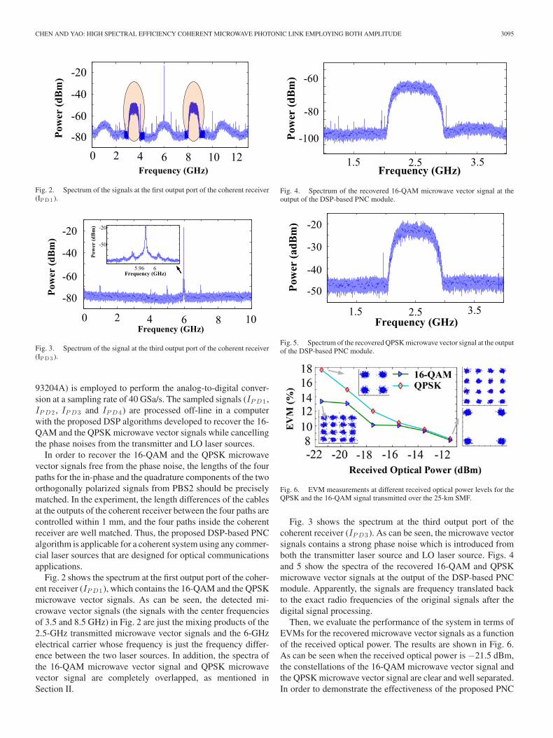
Fig. 6. EVM measurements at different received optical power levels for theQPSK and the 16-QAM signal transmitted over the 25-km SMF.
Fig. 3 shows the spectrum at the third output port of thecoherent receiver (IP D3). As can be seen, the microwave vectorsignals contains a strong phase noise which is introduced fromboth the transmitter laser source and LO laser source. Figs. 4and 5 show the spectra of the recovered 16-QAM and QPSKmicrowave vector signals at the output of the DSP-based PNCmodule. Apparently, the signals are frequency translated backto the exact radio frequencies of the original signals after thedigital signal processing.
Then, we evaluate the performance of the system in terms ofEVMs for the recovered microwave vector signals as a functionof the received optical power. The results are shown in Fig. 6.As can be seen when the received optical power is −21.5 dBm,the constellations of the 16-QAM microwave vector signal andthe QPSK microwave vector signal are clear and well separated.In order to demonstrate the effectiveness of the proposed PNC

3096 JOURNAL OF LIGHTWAVE TECHNOLOGY, VOL. 33, NO. 14, JULY 15, 2015
Fig. 7. Schematic diagrams of (a) an IM/CD MPL, and (b) a PM/CD MPLwithout digital PNC module.
Fig. 8. Constellations of the detected QPSK microwave vector signal. (a) TheIM/CD MPL without digital PNC module, (b) the PM/CD MPL without digitalPNC module.
technique, we also measure the constellations of the detectedsignals for an IM/CD MPL and a PM/CD MPL without a digitalPNC module. The experiment setups are shown in Fig. 7(a) and(b). Here, the microwave vector signal for both setups is a QPSKsignal with a center frequency of 2.5 GHz and a symbol rate of625 MSymbol/s. The linewidth of the laser source is 100 KHz.As discussed in Section II, the output signals at XI ports of thecoherent receivers in Fig. 7(a) and (b) can be expressed as (12)and (13). Fig. 8(a) and (b) shows the constellations of the outputsignals at the XI ports of the coherent receivers in Fig. 7(a)and (b). As can be seen, the quality of the recovered QPSKmicrowave vector signals are very poor which confirms thatthe QPSK microwave vector signals for both cases are stronglyaffected by the phase noise.
Finally, we evaluate the BER performance of the system. As-suming that the noise after the digital PNC module is a stationaryrandom process with Gaussian statistics, we can calculate theBERs of M-ary QAM from the EVMs based on the relationshipgiven by
PM −QAM =2
log2 M
(1 − 1√
M
)
×erfc
(√3
2 (M − 1)× SNR
)
(19)
with
SNR = 1/EV M 2 (20)
where erfc () is the complementary error function and SNR isthe signal-to-noise ratio [14]–[17]. The BERs as a function ofthe received optical power calculated from the measured EVMsare shown in Fig. 9. Again, when the received optical power is−21.5 dBm, the BER is 10−8 for the QPSK signal, which issufficiently small to recover the original signal. The BER forthe 16-QAM signal is 10−4, which is poorer than that of theQPSK signal. By using a state-of-the-art forward error correc-tion (FEC) technique, the recovered signal would have a signal
Fig. 9. BERs at different received optical power levels for the QPSK and the16-QAM microwave vector signals transmitted over 25-km SMF.
quality that is still suitable for error-free transmission [6], [18],[19]. When the received optical power is –13.5 dBm, accordingto (19), the estimated signal-to-noise ratios of the QPSK and16-QAM microwave vector signals after the PNC module are20.45 and 20.61 dB, respectively. For such signal-to-noise ra-tios, error-free detection with higher-order modulation formatscan be achieved by using the FEC techniques. Considering theFEC limit (The FEC technique can be applied to improve a rawBER of up to 3 × 10⁻³ to an effective BER of 1 × 10⁻¹⁵, atthe expense of a 6.7% overhead [19]), for a signal with a signal-to-noise ratio of 20.45 dB, the highest-order modulation formatfor error-free detection is 32-QAM. So the spectrum efficiencyof the proposed scheme can reach 10 bit/s/Hz. For the conven-tional IM/DD MPL in [7], when the received optical power was–12.5 dBm, since the SNR and the estimated BER of the re-ceived microwave vector signal were 9.3299 dB and 3 × 10⁻³,the highest-order modulation format for error-free detection isQPSK. So the spectral efficiency is only 2 bit/s/Hz.
IV. CONCLUSION
A high spectral efficiency coherent MPL supporting simulta-neous amplitude and phase modulation with digital phase noisecancellation was proposed and experimentally demonstrated.Through advanced DSP, amplitude- and phase-modulated mi-crowave vector signals could be recovered and the phase noiseintroduced by both the transmitter laser source and LO lasersource could be effectively cancelled. The proposed tech-nique was evaluated experimentally. Two microwave vectorsignals with one being a 16-QAM microwave vector signal at2.5 Gb/s and another being a QPSK microwave vector signal at1.25 Gb/s were transmitted over a 25-km SMF link and recov-ered at the receiver. The EVMs for the recovered 16-QAM andQPSK microwave vector signals were measured to be 8.05%and 8.23%, respectively, which are good enough to achieveerror-free transmission with FEC.
REFERENCES
[1] A. J. Seeds, “Microwave photonics,” IEEE Trans. Microw. Theory Tech.,vol. 50, no. 3, pp. 877–887, Mar. 2002.
[2] J. P. Yao “Microwave photonics,” J. Lightw. Technol., vol. 27, no. 3,pp. 314–335, Feb. 2009.
[3] J. Capmany and D. Novak, “Microwave photonics combines two worlds,”Nature Photon., vol. 1, no. 6, pp. 319–330, Jun. 2007.
[4] G. P. Agrawal, Fiber-Optic Communication Systems, 3rd ed. Hoboken,NJ, USA: Wiley, 2002, pp. 478–479.

CHEN AND YAO: HIGH SPECTRAL EFFICIENCY COHERENT MICROWAVE PHOTONIC LINK EMPLOYING BOTH AMPLITUDE 3097
[5] A. Caballero, D. Zibar, and I. T. Monroy, “Performance evaluation ofdigital coherent receivers for phase-modulated radio-over-fiber links,” J.Lightw. Technol., vol. 29, no. 21, pp. 3282–3292, Nov. 2011.
[6] A. Caballero, D. Zibar, and I. T. Monroy, “Digital coherent detectionof multi-gigabit 40 GHz carrier frequency radio-over-fibre signals usingphotonic down conversion,” Electron. Lett., vol. 46, no. 1, pp. 57–58, Jan.2010.
[7] X. Chen, T. Shao, and J. P. Yao, “Digital phase noise cancellation fora coherent-detection microwave photonic link,” IEEE Photon. Technol.Lett., vol. 26, no. 8, pp. 805–808, Apr. 2014.
[8] X. Chen and J. P. Yao “A coherent microwave photonic link with digitalphase noise cancellation,” in Proc. IEEE Int. Top. Meet. Microw. Photon.Conf., Oct. 2014, pp. 438–441.
[9] Y. Chen, T. Shao, A. Wen, and J. P. Yao, “Microwave vector signalstransmission over an optical fiber based on IQ modulation and coherentdetection,” Opt. Lett., vol. 39, no. 6, pp. 1509–1512, Mar. 2014.
[10] Y. Pei, J. P. Yao, K. Xu, J. Li, Y. Dai, and J. Lin, “Advanced DSP techniquefor dynamic range improvement of a phase-modulation and coherent-detection microwave photonic link,” in Proc. IEEE Int. Top. Meet. Microw.Photon. Conf., Oct. 2013, pp. 72–75.
[11] T. R. Clark and M. L. Dennis, “Coherent optical phase-modulation link,”IEEE Photon. Technol. Lett., vol. 19, no. 16, pp. 1206–1208, Aug. 2007.
[12] T. R. Clark, S. R. O’Connor, and M. L. Dennis, “A phase-modulation I/Q-demodulation microwave-to-digital photonic link,” IEEE Trans. Microw.Theory Tech., vol. 58, no. 11, pp. 3069–3058, Nov. 2010.
[13] X. S. Yao, L.-S. Yan, B. Zhang, A. E. Willner, and J. Jiang, “All-opticscheme for automatic polarization division demultiplexing,” Opt. Exp.,vol. 15, no. 12, pp. 7407–7414, Jun. 2007.
[14] D. H. Wolaver, “Measure error rates quickly and accurately,” Electron.Des., vol. 43, no. 11, pp. 89–98, May. 1995.
[15] A. Brillant, Digital and Analog Fiber Optic Communication for CATV andFTTx Applications. Bellingham, WA, USA: SPIE, 2008, pp. 653–660.
[16] V. J. Urick, J. X. Qiu, and F. Bucholtz, “Wide-band QAM-over-fiberusing phase modulation and interferometric demodulation,” IEEE Photon.Technol. Lett., vol. 16, no. 10, pp. 2374–2376, Oct. 2004.
[17] G. P. Agrawal, Fiber-Optic Communication Systems, 4th ed. Hoboken,NJ, USA: Wiley, 2010, pp. 151–157.
[18] G. Hill, The Cable and Telecommunications Professionals’ Reference:Transport Networks, vol. 3. Burlington, MA, USA: Focal Press, 2008,pp. 203–206.
[19] R. Schmogrow, D. Hillerkuss, S. Wolf, B. Bauerle, M. Winter, P. Kleinow,B. Nebendahl, T. Dippon, P. C. Schindler, C. Koos, W. Freude, andJ. Leuthold, “512QAM Nyquist sinc-pulse transmission at 54 Gbit/s inan optical bandwidth of 3 GHz,” Opt. Exp., vol. 20, no. 6, pp. 6439–6447,Mar. 2012.
Xiang Chen (S’13) received the B.Eng. degree in communications engineer-ing from the Donghua University, Shanghai, China, in 2009, and the M.Sc.degree in communications and information engineering from Shanghai Uni-versity, Shanghai, in 2012. He is currently working toward the Ph.D. degreein electrical and computer engineering at the Microwave Photonics ResearchLaboratory, School of Electrical Engineering and Computer Science, Universityof Ottawa, Ottawa, ON, Canada.
His current research interests include coherent radio-over-fiber systems andthe dynamic range of analog optical links.
Jianping Yao (M’99–SM’01–F’12) received the Ph.D. degree in electrical en-gineering from the Universite de Toulon, Toulon, France, in December 1997.
In 1998, he joined the School of Electrical and Electronic Engineering,Nanyang Technological University, Singapore, as an Assistant Professor. In De-cember 2001, he joined the School of Electrical Engineering and ComputerScience, University of Ottawa, Ottawa, ON, Canada, as an Assistant Professor,where he became an Associate Professor in 2003, and a Full Professor in 2006.In 2007, he was appointed the University Research Chair in Microwave Photon-ics. From July 2007 to June 2010, he was the Director of the Ottawa-CarletonInstitute for Electrical and Computer Engineering, where he was reappointedthe Director in 2013. He is currently a Professor and University Research Chairwith the School of Electrical Engineering and Computer Science, Universityof Ottawa. He has published more than 470 papers, including more than 270papers in peer-reviewed journals and 200 papers in conference proceedings.
Dr. Yao is a Registered Professional Engineer of Ontario. He is a Fellow ofthe Optical Society of America and the Canadian Academy of Engineering. Heis an IEEE MTT-S Distinguished Microwave Lecturer for 2013–2015. He wasa Guest Editor for the Focus Issue on Microwave Photonics in Optics Expressand Feature Issue on Microwave Photonics in Photonics Research, in 2013and 2014, respectively. He is currently a Topical Editor for Optics Letters, andserves on the Editorial Board of the IEEE TRANSACTIONS ON MICROWAVE THE-ORY AND TECHNIQUES, Optics Communications, and China Science Bulletin.He is the Chair of numerous international conferences, symposia, and work-shops, including the Vice Technical Program Committee (TPC) Chair of theIEEE Microwave Photonics Conference in 2007, the TPC Cochair of the Asia-Pacific Microwave Photonics Conference, in 2009 and 2010, the TPC Chair ofthe high-speed and broadband wireless technologies subcommittee of the IEEERadio Wireless Symposium from 2009 to 2012, the TPC Chair of the microwavephotonics subcommittee of the IEEE Photonics Society Annual Meeting in 2009,the TPC Chair of the IEEE Microwave Photonics Conference in 2010, the Gen-eral Cochair of the IEEE Microwave Photonics Conference in 2011, the TPCCochair of the IEEE Microwave Photonics Conference in 2014, and the GeneralCochair of the IEEE Microwave Photonics Conference in 2015. He received theInternational Creative Research Award at the University of Ottawa in 2005 andhe also received the George S. Glinski Award for excellence in research in 2007.He was selected to receive an inaugural OSA Outstanding Reviewer Award in2012.