Embed Size (px)
Citation preview

Element Data Collection Manual
2007

NOTES

ACKNOWLEDGEMENTS Additional elements and comments have been added to assist inspectors in coding conditions observed in the field. These comments and elements were based on Virginia’s experience and were collected from Central Office and District bridge personnel.

BMS Element Level Data Collection Manual - 2007 Page i
TABLE OF CONTENTS V Denotes Virginia specific elements. S Denotes Virginia sub-elements. INTRODUCTION TO BRIDGE MANAGEMENT SYSTEMS AND PONTIS ...........................1
BRIDGE MANAGEMENT SYSTEM....................................................................................1 Why are Bridge Management Systems Needed .............................................................1 A Brief History of Bridge Management ............................................................................1 The Needs of a Bridge Management System (BMS) ......................................................1 NBI Compatibility .............................................................................................................2 The Role of Bridge Inspectors.........................................................................................2
PONTIS ..............................................................................................................................2 Element Level Data Inspection........................................................................................2 Commonly Recognized (CoRe) Elements.......................................................................3 Sub-Elements..................................................................................................................3 Smart Flags .....................................................................................................................4 Non-CoRe Elements........................................................................................................4
Element Level Rating Examples ............................................................................................6 Uncoated Steel/Metal - Elements ..........................................................................................9
101 Steel Closed Web/Box Girder - Uncoated (LF) .........................................................9 106 Steel Open Girder - Uncoated (LF) ...........................................................................9 108V Steel Open Girder with Timber Deck – Coated and Uncoated (LF).........................9 112 Steel Stringer - Uncoated (LF) ..................................................................................9 120 Steel Bottom Chord of Through Truss - Uncoated (LF) ............................................9 125 Steel Through Truss excluding bottom chord - Uncoated (LF) .................................9 130 Steel Deck Truss - Uncoated (LF) ............................................................................9 140 Steel Arch - Uncoated (LF) .......................................................................................9 146 Steel Cable - Uncoated (not embedded in concrete) (EA)........................................9 151 Steel Floor Beam - Uncoated (LF) ............................................................................9 160 Steel Pin and/or Pin & Hanger Assembly - Uncoated (EA).......................................9 201 Steel Column or Pile Extension - Uncoated (EA)......................................................9 225 Steel Submerged Pile (EA) .......................................................................................9 230 Steel Pier Cap - Uncoated (LF).................................................................................9 330 Metal Bridge Railing - Uncoated (LF)........................................................................9
Uncoated Steel/Metal - Condition States ...............................................................................11 Coated Steel/Metal - Elements ..............................................................................................12
98V Steel Sidewalk, Open Grid - Coated (LF)..................................................................12 102 Steel Closed Web/Box Girder - Coated (LF).............................................................12 107 Steel Open Girder - Coated (LF)...............................................................................12 108V Steel Open Girder with Timber Deck – Coated and Uncoated (LF).........................12 113 Steel Stringer - Coated (LF)......................................................................................12 121 Steel Bottom Chord of Through Truss - Coated (LF) ................................................12 126 Steel Through Truss excluding bottom chord - Coated (LF) .....................................12 131 Steel Deck Truss - Coated (LF) ................................................................................12 141 Steel Arch - Coated (LF) ...........................................................................................12 147 Steel Cable (not embedded in concrete) - Coated (EA)............................................12 152 Steel Floor Beam - Coated (LF) ................................................................................12 161 Steel Pin and/or Pin & Hanger Assembly - Coated (EA)...........................................12 202 Steel Column or Pile Extension - Coated (EA)..........................................................12 231 Steel Pier Cap - Coated (LF) ....................................................................................12 334 Metal Bridge Railing - Coated (LF) ...........................................................................12

BMS Element Level Data Collection Manual - 2007 Page ii
Coated Steel/Metal - Condition States...................................................................................13 Prestressed (P/S) Concrete - Elements.................................................................................14
104 P/S Concrete Voided and Unvoided Closed Web/Box Girder (LF) ...........................14 109 P/S Concrete Open Girder (LF) ................................................................................14 115 P/S Concrete Stringer (LF) .......................................................................................14 143 P/S Concrete Arch (LF).............................................................................................14 154 P/S Concrete Floor Beam (LF)..................................................................................14 204 P/S Concrete Column or Pile Extension (EA) ...........................................................14 226 P/S Concrete Submerged Pile (EA) ..........................................................................14 233 P/S Concrete Pier Cap (LF) ......................................................................................14
Prestressed (P/S) Concrete - Condition States .....................................................................15 Reinforced Concrete - Elements............................................................................................16
92V Reinforced Concrete Sidewalk (LF) ..........................................................................16 105 Reinforced Concrete Voided and Unvoided Closed Web/Box Girder (LF) ...............16 110 Reinforced Concrete Open Girder (LF).....................................................................16 116 Reinforced Concrete Stringer (LF)............................................................................16 144 Reinforced Concrete Arch (LF) .................................................................................16 155 Reinforced Concrete Floor Beam (LF) ......................................................................16 205 Reinforced Concrete Column or Pile Extension (EA)................................................16 210 Reinforced Concrete Pier Wall (LF) ..........................................................................16 215 Reinforced Concrete Abutment (LF) .........................................................................16 220 Reinforced Concrete Submerged Pile Cap/Footing (EA)..........................................16 227 Reinforced Concrete Submerged Pile (EA) ..............................................................16 234 Reinforced Concrete Pier Cap (LF) ..........................................................................16 295V Reinforced Concrete Wingwalls (LF) ........................................................................16 331 Reinforced Concrete Bridge Railing (LF) ..................................................................16
Reinforced Concrete - Condition States ................................................................................17 Timber - Elements..................................................................................................................18
94V Timber Sidewalk (LF)................................................................................................18 111 Timber Open Girder (LF)...........................................................................................18 117 Timber Stringer (LF)..................................................................................................18 135 Timber Truss or Arch (LF).........................................................................................18 156 Timber Floor Beam (LF)............................................................................................18 206 Timber Column or Pile Extension (EA) .....................................................................18 216 Timber Abutment (LF) ...............................................................................................18 228 Timber Submerged Pile (EA) ....................................................................................18 235 Timber Pier Cap (LF) ................................................................................................18 296V Timber Wingwalls (LF) ..............................................................................................18 332 Timber Bridge Railing (LF)........................................................................................18
Timber - Condition States ......................................................................................................19 Other Material - Elements ......................................................................................................20
145 Other Material Arch (LF) ...........................................................................................20 211 Other Material Pier Wall (LF) ....................................................................................20 217 Other Material Abutment (LF) ...................................................................................20 297V Other Material Wingwalls (LF) ..................................................................................20 333 Combination/Miscellaneous Bridge Railing (LF) .......................................................20
Other Material - Condition States...........................................................................................21 Mechanically Stabilized Earth - Elements..............................................................................22
444 Mechanically Stabilized Earth - Abutment (LF) ........................................................22 445 Mechanically Stabilized Earth - Wingwall/Retaining Wall (LF).................................22
Mechanically Stabilized Earth - Condition States ..................................................................23 Concrete Deck and Concrete Slab - Elements ......................................................................24

BMS Element Level Data Collection Manual - 2007 Page iii
12 Concrete Deck - Bare - with Uncoated Reinforcement (EA) .....................................24 13 Concrete Deck - with asphaltic concrete (AC) Overlay - w/o Membrane (EA)..........24 14 Concrete Deck - with AC Overlay - with Membrane (EA) .........................................24 18 Concrete Deck - Thin Overlay (less than 1”) - no AC Overlay (EA) ..........................24 22 Concrete Deck - Rigid Overlay (greater than 1”) - no AC Overlay (EA)....................24 26 Concrete Deck - Bare - with Coated Reinforcement (EA).........................................24 27 Concrete Deck - with Cathodic Protection (EA) ........................................................24 38 Concrete Slab - Bare - with Uncoated Reinforcement (EA) ......................................24 39 Concrete Slab - with AC Overlay - w/o Membrane (EA) ...........................................24 40 Concrete Slab - with AC Overlay - with Membrane (EA) ..........................................24 44 Concrete Slab - Thin Overlay (less than 1”) - no AC Overlay (EA) ...........................24 48 Concrete Slab - Rigid Overlay (greater than 1”) - no AC Overlay (EA).....................24 52 Concrete Slab - Bare - with Coated Reinforcement (EA)..........................................24 53 Concrete Slab - with Cathodic Protection (EA) .........................................................24 738VS Concrete Slab - Covered with Fill (EA) .....................................................................24
Concrete Deck and Concrete Slab - Condition States...........................................................25 Metal Deck - Elements...........................................................................................................26
28 Steel Deck - Open Grid (EA).....................................................................................26 29 Steel Deck - Concrete Filled Grid (EA) .....................................................................26 30 Metal Deck - Corrugated/Orthotropic, Etc. (EA)........................................................26
Metal Deck - Condition States ...............................................................................................27 Timber Deck - Elements ........................................................................................................28
31 Timber Deck - (EA) ...................................................................................................28 32 Timber Deck - with asphaltic concrete (AC) Overlay (EA) ........................................28 54 Timber Slab - (EA) ....................................................................................................28 55 Timber Slab - with asphaltic concrete (AC) Overlay (EA) .........................................28
Timber Deck - Condition States .............................................................................................29 Culvert - Elements .................................................................................................................30
240 Metal Culvert (LF along length of barrel) ..................................................................30 241 Concrete Culvert (LF along length of barrel).............................................................30 242 Timber Culvert (LF along length of barrel) ................................................................30 243 Other Culvert (LF along length of barrel) ..................................................................30
Culvert - Condition States ......................................................................................................31 Slope Protection - Elements and Condition States ................................................................32
285V Slope - Protected (EA) ..............................................................................................32 286V Slope - Unprotected (EA)..........................................................................................33
Expansion Joint - Elements ...................................................................................................34 300 Strip Seal Expansion Joint (LF) ................................................................................34 301 Pourable Joint Seal (LF) ...........................................................................................34 302 Compression Joint Seal (LF) ....................................................................................34 303 Assembly Joint/Seal (LF) ..........................................................................................34 304 Open Expansion Joint (LF) .......................................................................................34
Expansion Joint - Condition States ........................................................................................35 Bearing - Elements ................................................................................................................36
310 Elastomeric Bearing (EA)..........................................................................................36 311 Moveable Bearing (Roller, sliding, etc.) (EA) ............................................................36 312 Enclosed/Concealed Bearing or Bearing System (EA) .............................................36 313 Fixed Bearing (EA)....................................................................................................36 314 Pot Bearing (EA) .......................................................................................................36 315 Disk Bearing (EA) .....................................................................................................36
Bearing - Condition States .....................................................................................................37 Approach Slab – Elements and Condition States ..................................................................38

BMS Element Level Data Collection Manual - 2007 Page iv
320 Prestressed Concrete Approach Slab (EA) ..............................................................38 321 Reinforced Concrete Approach Slab (EA) ................................................................38
Smart Flags............................................................................................................................39 298V Culvert Endwall/Headwall .........................................................................................39 299V Culvert Wingwall .......................................................................................................39 356 Steel Fatigue (EA).....................................................................................................39 357 Pack Rust (EA) .........................................................................................................39 358 Deck Cracking (EA) ..................................................................................................39 359 Soffit of Concrete Decks/Slabs (EA) .........................................................................39 360 Settlement (EA).........................................................................................................39 361 Scour (EA) ................................................................................................................39 362 Traffic Impact Damage (EA)......................................................................................39 363 Section Loss (EA) .....................................................................................................39 701V Utilities (EA) ..............................................................................................................39 702V Drains (EA) ...............................................................................................................39 703V Lighting (EA) .............................................................................................................39 704V Roadway Over Culverts (EA) ....................................................................................39 706V Soffit of Overhang of Concrete Decks/Slabs (EA) ....................................................40 707V Soffit of Concrete Decks/Slabs with SIP Forms (EA)................................................40 708V Debris in Channel (EA) .............................................................................................40 709V Structure Replacement (EA) .....................................................................................40 710V Deck Replacement (EA) ...........................................................................................40
Smart Flags - Condition States ..............................................................................................41 298V Culvert Endwall/Headwall (EA) ..................................................................................41 299V Culvert Wingwall (EA) ................................................................................................42 356 Steel Fatigue (EA).....................................................................................................43 357 Pack Rust (EA) .........................................................................................................43 358 Deck Cracking (EA) ..................................................................................................44 359 Soffit of Concrete Decks/Slabs (EA) .........................................................................44 360 Settlement (EA).........................................................................................................45 361 Scour (EA) ................................................................................................................45 362 Traffic Impact Damage (EA)......................................................................................46 363 Section Loss (EA) .....................................................................................................46 701V Utilities (EA) ..............................................................................................................47 702V Drains (EA) ...............................................................................................................48 703V Lighting (EA) .............................................................................................................49 704V Roadway Over Culverts (EA) ....................................................................................50 706V Soffit of Overhang of Concrete Decks/Slabs (EA) ....................................................51 707V Soffit of Concrete Decks/Slabs with SIP Forms (EA)................................................52 708V Debris in Channel (EA) .............................................................................................53 709V Structure Replacement (EA) .....................................................................................53 710V Deck Replacement (EA) ...........................................................................................54
DEFINITIONS AND GUIDANCE FOR DETERMINING ELEMENTS AND QUANTITIES......55 GENERAL NOTES .............................................................................................................55 FOOTBRIDGES AND PEDESTRIAN BRIDGES................................................................55 DECK ELEMENTS .............................................................................................................55
Deck Area ....................................................................................................................55 Decks and Slabs ..........................................................................................................55 Decks - Multiple............................................................................................................55
SUPERSTRUCTURE ELEMENTS.....................................................................................56 Reinforced Channels (Adjacent) ..................................................................................56 Reinforced Channels (Spread).................................................................................57

BMS Element Level Data Collection Manual - 2007 Page v
Cast-in-Place Concrete Multi-cell Box Girders.............................................................57 Cast-in-Place Concrete Tee Beam ..............................................................................58 Reinforced Concrete Voided and Unvoided Closed Web/Box Girder (Adjacent).........59 Reinforced Concrete Voided and Unvoided Closed Web/Box Girder (Spread) ...........60 Stringers/Floor Beams/Girders.....................................................................................60 Steel Diaphragms/Cross Frames that are a part of a curved girder system. ...............61
SUBSTRUCTURE ELEMENTS..........................................................................................61 Abutments - General ....................................................................................................61 Wingwalls - Non-Integral and Integral ..........................................................................61 Timber Abutments/Bents/Piers/Pile Bents, Etc. ...........................................................62 General ........................................................................................................................62 Timber Bent..................................................................................................................63 Spill-Through Abutments..............................................................................................64 Piers - General .............................................................................................................65 Column Bent ................................................................................................................65 Hammer Head Pier ......................................................................................................66 Pile Bent.......................................................................................................................66 Column Bent With Submerged Pile Cap ......................................................................67
RIGID FRAMES AND THREE SIDED STRUCTURES.......................................................67 Steel (Frame) ...............................................................................................................67 Concrete (Three Sided Structure) ................................................................................68
BRIDGE RAILING, CURBS, SIDEWALKS, MEDIANS AND TERMINAL WALLS..............68 CULVERTS.........................................................................................................................69
Wingwalls/Endwalls......................................................................................................69 PRESTRESSED CONCRETE SLABS - VOIDED AND UNVOIDED..................................70 REINFORCED FIBER POLYMER (RFP) ...........................................................................70 SLAB SPANS COVERED WITH FILL ................................................................................71 SLOPE ELEMENTS ...........................................................................................................71 TRUSSES...........................................................................................................................72
Through Truss (includes Pony Trusses) ......................................................................72 Deck Truss ...................................................................................................................73 Deterioration.................................................................................................................73 Diagonals .....................................................................................................................73 Portals/Bracing.............................................................................................................73 Through Truss (includes Pony Trusses) ......................................................................74
WEIGH SCALE PITS..........................................................................................................74 ARCHES.............................................................................................................................75
Concrete Deck Arches – Covered With Fill ..................................................................75 WEARING SURFACE ........................................................................................................75
INDEX ....................................................................................................................................76
BMS Element Level Data Collection Manual - 2007 Page vi
ELEMENT TABLE (element number) SUPERSTRUCTURE STEEL STEEL P/S REINF.
Units UNCOAT COATED CONC CONC TIMBER OTHER
Closed Web/Box Girder LF 101 102 104 105
Open Girder/Stringer LF 106 107 109 110 111
Open Girder/stringer with timber deck LF 108 108
Stringer (stringer/floorbeam system) LF 112 113 115 116 117
Thru Truss (Bottom Chord) LF 120 121
Thru Truss (Excluding Bottom Chord) LF 125 126
Deck Truss LF 130 131
Timber Truss/Arch LF 135
Arch LF 140 141 143 144 145
Cable (not embedded in concrete) EA 146 147
Floor Beam LF 151 152 154 155 156
Pin and Hanger Assembly EA 160 161
SUBSTRUCTURE STEEL STEEL P/S REINF.
Units UNCOAT COATED CONC CONC TIMBER OTHER
Column or Pile Extension EA 201 202 204 205 206
Pier Wall LF 210 211
Abutment LF 215 216 217
Wingwall LF 295 296 297
Submerged Pile Cap/Footing EA 220
Submerged Pile EA 225 226 227 228
Cap LF 230 231 233 234 235
Culvert LF 240 241 242 243
OTHER SUPER / SUB METAL METAL P/S REINF.
Units UNCOAT COATED CONC. CONC. TIMBER OTHER
Strip Seal Expansion Joint LF 300
Pourable Joint Seal LF 301
Compression Joint Seal LF 302
Assembly Joint/Seal (Modular) LF 303
Open Expansion Joint LF 304
Elastomeric Bearing EA 310
Movable Bearing (roller, sliding, etc.) EA 311
Enclosed/Concealed Bearing EA 312
Fixed Bearing EA 313
Pot Bearing EA 314
Disk Bearing EA 315
Approach Slab EA 320 321
Bridge Railing LF 330 334 331 332 333
Sidewalk LF 98 92 94
(continued)

BMS Element Level Data Collection Manual - 2007 Page vii
ELEMENT TABLE (element number). (continued) DECKS/SLABS
Units DECKS SLABS
Concrete (Bare) EA 12 38 Concrete Covered with Fill EA 738 Concrete Unprotected w/AC EA 13 39
Concrete Protected w/AC Overlay EA 14 40
Concrete w/Thin Overlay EA 18 44
Concrete w/Rigid Overlay EA 22 48
Concrete w/Coated Bars EA 26 52
Concrete w/Cathodic Protection EA 27 53
Open Grid - Steel EA 28
Concrete Filled Grid - Steel EA 29
Corrugated/Orthotropic/Etc. EA 30
Timber (Bare) EA 31 54
Timber w/AC Overlay EA 32 55
OTHER Units
MSE Abutment LF 444
MSE Wingwall/Retaining Wall LF 445
SMART FLAGS
Units
Slope - Protected EA 285 Slope - Unprotected EA 286
Culvert Endwall/Headwall EA 298
Culvert Wingwall EA 299
Steel Fatigue EA 356
Pack Rust EA 357
Deck Cracking EA 358
Soffit of Deck EA 359
Settlement EA 360
Scour EA 361
Traffic Impact EA 362
Section Loss EA 363
Utilities EA 701
Drains EA 702
Lighting EA 703 Roadway over Culvert EA 704
Underside of Overhang EA 706
Soffit w/ SIP Forms EA 707
Debris in Channel EA 708
Structure Replacemenrt EA 709
Deck Replacement EA 710

BMS Element Level Data Collection Manual - 2007 Page 1
INTRODUCTION TO BRIDGE MANAGEMENT SYSTEMS AND PONTIS
BRIDGE MANAGEMENT SYSTEM Why are Bridge Management Systems Needed Available funding is insufficient to address all the bridge needs. Wise management of the bridge inventory is required to ensure the best use of limited resources. A key bridge management system concept is that the best action for an individual bridge may not be the best action for the entire inventory when faced with limited resources. Bridge failures cannot be tolerated. However, safety, preservation of investment and uninterrupted service must be included in any management decision process. A bridge management system (BMS) provides the tools to consider where and when to best spend funds. A Brief History of Bridge Management In the late 1960s/early 1970s, the National Bridge Inventory (NBI) was created and the National Bridge Inspection Standards (NBIS) were introduced. To assist the states in meeting this goal, a Recording and Coding Guide for the Structure Inventory and Appraisal of the Nation’s Bridges was written. Since then, the requirements for bridge inspections have basically remained unchanged. The Federal Highway Administration (FHWA) continues to use the data collected during bridge safety inspections to determine the extent of a state’s eligibility for federal funding for its bridge programs. In the 1980s, concerns were raised about whether use of the NBI was resulting in the most economically realistic needs in view of the limited funds available. In 1985, the FHWA initiated a two-phase demonstration project to refine the concept of BMS. Phase one called for a review of existing state BMS practices and a synthesis of fundamental elements of a national BMS. Phase two developed a computer tool that any state could use to manage its bridge inventory. This tool eventually was called Pontis. The Needs of a Bridge Management System (BMS) A good BMS is a comprehensive database of bridge, traffic, cost and safety data and an ongoing program for data collection and an analytical tool to systematically yield a network-level analysis and optimization of bridge data. Unlike the way engineers handled the bridge program in the past, we now need to look at network and project level programs. The major difference is that network-level analysis deals with the entire bridge inventory whereas project-level analysis looks at single bridges. Network analysis is geared at overcoming the traditional practice of examining projects one at a time, in isolation from one another. It provides an initial indication of the best action to take for each bridge to promote the health of the network.

BMS Element Level Data Collection Manual - 2007 Page 2
Using a bridge management system, a transportation agency should be able to:
(1) predict deterioration with and without intervening actions; (2) identify feasible actions to improve condition, safety, or the ability of an element to
function as intended; (3) estimate costs and savings; (4) determine maintenance strategies; (5) optimize a program over a specified period with limited funds; and (6) generate reports quantifying bridge needs for use by legislative budget makers.
NBI Compatibility The adoption of BMS does not change the federal requirements to submit NBI data. The FHWA has no plans to change the NBI or the way in which federal funding is allocated. Therefore, all NBI data are still required. The Role of Bridge Inspectors A good bridge database and a functional bridge management system are entirely dependent on good bridge inspection data. A bridge inspector needs to be familiar with the concept of breaking a bridge down into its component elements and assigning a condition state to each element based generally on visual observations and the condition state language provided in this manual. PONTIS Pontis is a database containing bridge condition data, traffic needs, accident data, maintenance, improvement and replacement costs, available money, etc. From all this data, a prioritized list of bridge needs can be produced that optimizes the limited funds available. Pontis, from the Latin pons (bridge), differs from the existing NBI inspection program and the system for prioritizing bridge needs currently being used. The description of the condition of the individual bridge components is more detailed and the Pontis program will analyze all the related data with respect to the entire network, or family, of bridges in the inventory. Information is collected on elements that have predictable deterioration rates that are important for the deterioration models used in Pontis. Element Level Data Inspection Under the NBI inspection program, bridge components or items are coded with an inspection rating of ‘0’ (worst) through ‘9’ (best). The guidelines of the NBIS require inspectors to give an average rating to provide an overall indication of the general condition of the entire component being rated. Pontis looks at things differently with ‘1’ being the best and 3’, 4’, or ‘5’ being the worst depending on the particular element. Then, rather than an average rating, bridge elements are rated in quantitative units so that an inspector rates the entire element for the NBIS and subdivides it into various condition states for Pontis. An element is a major component of a bridge (such as abutments, girders, piles, caps, etc.) that can be further subdivided by material type (such as prestressed concrete, timber, weathering steel, etc.). Elements have defined deterioration rates and units that are descriptive and easily measured. Each bridge will not have all the possible elements, and more likely will have under a dozen. Each element has a set of defined condition states. There are at least three states and at most five states for each element. These states range from “new” to “badly deteriorated.” Condition state language is not an attempt to define an element as good, fair or poor.

BMS Element Level Data Collection Manual - 2007 Page 3
In addition to the condition of a bridge element, its environment, the effects of traffic and the effects of aging govern its rate of deterioration. To relate these environmental effects, each element of a bridge is placed in one of four categories:
• Benign - Neither environmental factors nor operating practices are likely to change the condition of the element over time.
• Low - Environmental factors or operating practices do not adversely affect condition of the element.
• Moderate - Changes in element condition are normal as measured against environmental factors and/or operating practices.
• Severe - Environmental factors or operating practices contribute to the rapid decline in the condition of the element.
It is reasonable that an element can have multiple condition states. A good example of this is beam-ends. Assume there are 4 girders, each 100 feet long (a total of 400 LF) and only the beam-ends have advanced deterioration due to joint leakage. The entire 400 LF would not be coded in condition state 4 but only a portion of the total amount under the open joint. Also, the deterioration does not have to be on every beam or at each end. Importantly, a rating quantity of less than 1% of the total quantity should not be recorded. Pontis does not track a quantity less than 1% of the total amount for an element. Commonly Recognized (CoRe) Elements CoRe elements are those that are common to bridges nationwide. CoRe elements have consistent definitions, condition state language, and units of measure, and contribute to the NBI condition ratings (if the translator is used). A task force of 6 states (Minnesota, Oregon, Colorado, California, Virginia, and Washington) along with the FHWA developed the idea of using common bridge elements so data can be shared or reported nationally. In June 1993, the task force issued its final report. In it, they defined CoRe elements, sub-elements and smart flags. The FHWA has chosen to use this report as interim guidance for element level inspection. CoRe elements will be consistent nationwide for condition state language, units of measure and relationship to the NBI. These are a standard list of bridge elements, units of measure, condition states and feasible actions which would facilitate data sharing for costs and deterioration rates and patterns. A translator program has been issued by FHWA that converts appropriate Pontis CoRe element level data to the corresponding NBIS condition ratings. The University of Colorado and FHWA developed this conversion program to simplify the transition from Pontis to NBIS ratings. The FHWA translator program accesses the Pontis database and uses CoRe elements, sub-elements, and Smart Flags. At this time Virginia does not use the translator program. Sub-Elements A transportation agency can choose to add sub-elements. However, sub-elements must relate directly to a specific CoRe element. In order to be considered a sub-element, the following criteria must be met:
(1) the condition state language and feasible actions must remain the same as the parent CoRe element

BMS Element Level Data Collection Manual - 2007 Page 4
(2) the units of measure must remain the same as its parent CoRe element. Sub-elements are used in the NBIS translator program and are treated as CoRe elements. Sub-elements may be used if the physical size, location and environment are different, or if there are expected differences in deterioration rates or Maintenance, Repair & Rehabilitation (MR&R) costs within the parent CoRe element.
Smart Flags Smart flags are another feature of Pontis that is different from the NBI program. These “flags” look and operate like an element. They can be used to model specific problems or areas that do not exhibit a logical pattern of deterioration. Smart Flags do not have feasible actions associated with them. Therefore, they have no impact on the MR&R optimization models run by Pontis. However, Smart Flags are necessary for accurate NBI translation. Smart Flags are to be used to track distresses not included in the CoRe condition state language. When reading over the condition state language of any element in the manual, it should be noted that it is written for a specific type of deterioration. For example, look at Element No. 334 “Coated Metal Bridge Railing” in the manual. Note the condition state language is concerned with the condition of the coating system but does not address other problems with the rail system. The descriptions and condition state language for Smart Flags can be found in this manual. Currently eight Smart Flags (units: each) have been established for national use:
• Steel fatigue • Pack rust • Deck cracking • Soffit (underside of deck)
• Settlement • Scour • Traffic impact • Section loss
Non-CoRe Elements Non-CoRe elements are items that a transportation agency can add to its Pontis database for conditions or situations that are unique to its bridges or to a specific bridge. Also, this type of element is used for other non-major components of any bridge. Non-CoRe elements have condition state language and units of measure just as CoRe elements do. However, they are not used in the NBIS translator program. Examples of non-CoRe elements used in Virginia include:
• Slope protection • Wingwalls • Sidewalks
In addition, Virginia has added the following smart flags:
• Utilities • Drains • Lighting • Roadway over Culvert • Underside of deck overhang • Soffit for use with stay in place forms • Debris in Channel • Structure Replacement

BMS Element Level Data Collection Manual - 2007 Page 5

BMS Element Level Data Collection Manual - 2007 Page 6
Element Level Rating Examples Example No. 1 Description of Bridge This is a two-span, simply supported, rolled steel multi-beam bridge, with each span consisting of six beams. Two abutments and one pier support two spans constructed of reinforced concrete. The bridge has a deck width of 24 ft., no skew and structure length of 144 ft. This structure carries two lanes of traffic on Beaver Creek Road over the tributary to Beaver Creek. Calculating the Quantities
Beams Deck 144 ft. x 6 beams = 864 LF 144 ft. (span) x 24 c/c = 3,456 SF Expansion Bearings Bridge Railings 12 EA 144 ft. x 2 = 288 LF Fixed Bearings Pier 12 EA 24 LF Abutments Joints 26 ft. x 2 Abutments = 52 LF 3 joints x 24 ft = 72 LF
Summary of Condition States
• Top of the deck has delaminated concrete and several spalls with exposed rebar covering approximately 13% of the deck surface.
• Bridge railing is in good condition with no deficiencies. • Expansion joints are clean and functional. • Bottom of deck shows random areas of hairline cracking with rust stains and
efflorescence. • Minor pitting to a depth of 1/16 inch and paint scaling typical on all bottom flanges of the
beams. Top flanges are in good condition with the exception of areas near the end diaphragm connections where approximately 6 inches on each side of the connection from top to bottom exhibits 1/16 inch section loss.
• Cover plate end welds at three locations exhibited 4 inch long hairline cracks. • End diaphragms are showing pitting up to 1/16 inch depth. All diaphragms exhibit heavy
corrosion with steel flaking with no significant section loss. • Bearings are in fair condition with a minor build-up of pigeon droppings around the base
plates causing a failure of the paint system. • Abutment A has a full height vertical crack between beams No. 3 and No. 4. This crack
varies in width from 1/16 inch to 1/8 inch. • Abutment B is in good condition, with no deficiencies. • Pier is in good condition, with no deficiencies. • Abutment B has scour along the breastwall 28 feet long, 7 feet wide and 4 feet deep. • Upstream end of pier - build-up of sediment and debris 40 feet wide by 4 feet high.
Using the descriptions provided above and the condition state language for each appropriate element, data is recorded on a form such as the one shown below.

BMS Element Level Data Collection Manual - 2007 Page 7
BMS FIELD INSPECTION FORM
ELEM DESCRIPTION Env QUANTITY Units COND STATE QUANTITY CoRe/Non-CoRe Elements 1 2 3 4 5 #12 - Concrete Deck 3 1 (3456 sf) EA 1 (3456) #107 - Coated Stl Girder 3 864 LF 864 #210 - R.C. Pier Wall 3 24 LF 24 #215 - R.C Abutment 3 52 LF 51 1 #301 - Pourable Joint 3 72 LF 72 #311 - Movable Brgs. 3 12 EA 12 #313 - Fixed Brgs. 3 12 EA 12 #330 - Metal Railing 3 288 LF 288 Smart Flags #356 - Steel Fatigue 3 1 EA 1 #359 - Soffit 3 1 EA 1 #361 - Scour 3 1 EA 1
In the above example, a quantity was recorded in condition state 1 where appropriate. If condition state 1 is left blank, Pontis will assume the quantity to be the portion not assigned to other condition states. In other words, Pontis will subtract any quantities coded in condition states 2 through 5 from the total quantity and put any remaining quantity in condition state 1. Example No. 2 Description of Bridge This is a single span adjacent box beam bridge with a span length of 38 feet, a clear deck width of 26 feet and no skew. The cross section consists of seven beams and measures 28 feet out-to-out. The top flanges of the boxes are exposed as there is no applied wearing surface. Calculating the Quantities
Deck 38 ft. (span) x 26 ft. c/c = 988 SF Bridge Rail 38 ft. span x 2 = 76 LF Beams 38 ft. span x 7 beams = 266 LF Abutments 28 ft. x 2 Abutments = 56 LF

BMS Element Level Data Collection Manual - 2007 Page 8
Summary of Condition States
• Full width hairline transverse cracks can be found in the exposed top flange of Beam no. 6 for its full length as follows: Beam no. 3 for 4 LF from Abutment B, Beam no. 2 for 6 LF from Abutment B and Beam no. 4 for 3 LF from Abutment A. Typical crack spacing is 18 inches. The entire surface exhibits scaling less than 1/8” deep. Joint spaces between the beams were filled with road dirt.
• The metal bridge rail exhibits one 6 LF section which is partially detached from the support post.
• Full width hairline transverse flexure cracks can be found in the center 6 feet at the bottom flange of box beams no. 2 thru 5. The joints between the box beams leak, but there is no sign of rust stains or reinforcement damage.
• There is a 3/8 inch wide longitudinal crack in the bottom flange of Beam no. 6. The crack extends from Abutment A for 15 LF toward midspan. There is 15 SF of spalling around the longitudinal crack.
• The bearing seat under Beam no. 3 at Abutment A is spalled 4 inches deep for the full width of the beam. There is no reinforcing steel exposed. There is 15% loss of bearing in this area.
• The masonry stems and wingwalls are generally solid and intact with all joint mortar in place. One three foot stone in the stem of Abutment A exhibits hairline cracking and is weathered on the exposed surface. Abutment B stem exhibits a full-height, 1/16 inch wide crack under Beam #3, which extends through the masonry and concrete apron.
• Approximately 5 LF of the downstream corner of Abutment B exhibits a scour hole 10 feet in diameter and 3 feet deep which extends beneath the footing apron and approximately 1 foot of the abutment footing. The apron along the downstream wing exhibits a 1 inch wide crack due to settlement of the corner masonry of 1/16 inch.
BMS FIELD INSPECTION FORM
ELEM DESCRIPTION Env QUANTITY Units COND STATE QUANTITY CoRe/Non-CoRe Elements 1 2 3 4 5 #12 - Concrete Deck 3 1 (988 sf) EA 1 (988) #330 - Metal Railing 3 76 LF 70 6 #104 - P/S Concrete Closed Web Box Girder 3 266 LF 191 24 15
#217 - Other Abutment 3 56 LF 50 4 2 Smart Flags #358 - Deck Cracking 3 1 EA 1 #360 - Settlement 3 1 EA 1 #361 - Scour 3 1 EA 1

BMS Element Level Data Collection Manual - 2007 Page 9
Uncoated Steel/Metal - Elements ELEMENT DESCRIPTION 101 Steel Closed Web/Box Girder - Uncoated (LF) 106 Steel Open Girder - Uncoated (LF)
Includes two girder systems as well as rolled beams on multiple beam spans. 108V Steel Open Girder with Timber Deck – Coated and Uncoated (LF)
Includes two girder systems as well as rolled beams on multiple beam spans. This Element includes both coated and uncoated steel.
112 Steel Stringer - Uncoated (LF) Stringers are those elements that support the deck in a stringer-floor beam system.
120 Steel Bottom Chord of Through Truss - Uncoated (LF) Includes Pony trusses.
125 Steel Through Truss excluding bottom chord - Uncoated (LF) Includes Pony trusses.
130 Steel Deck Truss - Uncoated (LF) All members as well as the bottom chord.
140 Steel Arch - Uncoated (LF) All members of steel arches.
146 Steel Cable - Uncoated (not embedded in concrete) (EA) Post-tensioned structures, stays and suspension bridges.
151 Steel Floor Beam - Uncoated (LF) 160 Steel Pin and/or Pin & Hanger Assembly - Uncoated (EA)
Steel pin and hanger assemblies not coated or constructed of weathering steel or stainless steel.
201 Steel Column or Pile Extension - Uncoated (EA) 225 Steel Submerged Pile (EA)
Elements continuously submerged and are visible for inspection. The exposure may be intentional or caused by scour.
230 Steel Pier Cap - Uncoated (LF) 330 Metal Bridge Railing - Uncoated (LF)
All types and shapes of metal bridge railing that is neither painted nor coated (steel, aluminum, metal beam, rolled shapes, etc.).
NOTES: a) The term ‘Steel’ above also applies to all metal i.e. wrought iron, cast iron, aluminum, etc. b) Uncoated steel includes those elements constructed of weathering steel. c) Weathering steel elements that have been completely coated should be coded as the
appropriate coated steel element. d) If only one side and/or just the ends of a weathering steel element are coated (e.g., the
exterior face of a girder), the element should be considered uncoated steel. e) Galvanized or metallized steel shall be considered coated steel. f) See the back of this manual for definitions and guidance on coding ‘Steel Diaphragms/Cross
Frames’ that are a part of a curved girder system.
(continued)

BMS Element Level Data Collection Manual - 2007 Page 10
Uncoated Steel/Metal - Elements NOTES: (continued) g) When backwalls or bearing seats consist of a material different from the primary material of
the substructure unit, the condition of the backwall or the bearing seat will not be tracked using a Pontis element or smart flag.
h) For Steel Open Girders with a Timber Deck use Element 108 which is for both coated and uncoated steel
i) See the back of this manual for definitions and guidance on quantity.

BMS Element Level Data Collection Manual - 2007 Page 11
Uncoated Steel/Metal - Condition States CONDITION STATE DESCRIPTIONS 1 There is little or no corrosion of the uncoated steel. Weathering steel is coated uniformly and remains in excellent condition. Oxide film of weathering steel is tightly adhered. For uncoated cables, the strand and anchor sockets show no signs of distress. 2 Surface rust or surface pitting has formed or is forming on the uncoated steel.
However, the weathering steel has not corroded beyond design limits. Weathering steel color is yellow orange to light brown. Oxide film has a dusty to granular texture. For uncoated cables, the strand and anchor sockets show no signs of distress. 3 Steel has measurable section loss due to corrosion but does not warrant structural
analysis. Weathering steel is dark brown or black. Oxide film is flaking. For uncoated cables, the cable banding, if any, may show some loosening or slipping. For uncoated cables, the cable anchor devices may be loosening. 4 Corrosion is advanced. Oxide film has a laminar texture with thin sheets of rust. For uncoated cables, the cable strands or wires may be broken or severely abraded. For uncoated cables, the anchors may show signs of slippage. Section loss is sufficient to warrant structural analysis. Also code Element 363 (Section Loss). NOTES: a) If a Steel Pin and/or Pin and Hanger Assembly has a catcher beam, the catcher beam
should not influence the condition state selected for the pin and/or pin and hanger assembly. b) If the ability of the bridge railing to function as intended is affected by damaged posts or
unsupported rail, code as Condition State 4. Record the lineal feet of bridge rail affected by defective or missing post(s).

BMS Element Level Data Collection Manual - 2007 Page 12
Coated Steel/Metal - Elements ELEMENT DESCRIPTION 98V Steel Sidewalk, Open Grid - Coated (LF)
Sidewalks protected with coating, galvanizing, etc., which are 3’ wide or greater. This 3’ dimension distinguishes the sidewalk from the safety curb.
102 Steel Closed Web/Box Girder - Coated (LF) 107 Steel Open Girder - Coated (LF)
Includes two girder systems as well as rolled beams on multiple beam spans. 108V Steel Open Girder with Timber Deck – Coated and Uncoated (LF)
Includes two girder systems as well as rolled beams on multiple beam spans. This Element includes both coated and uncoated steel.
113 Steel Stringer - Coated (LF) Stringers are those elements that support the deck in a stringer-floor beam system.
121 Steel Bottom Chord of Through Truss - Coated (LF) Includes Pony trusses.
126 Steel Through Truss excluding bottom chord - Coated (LF) Includes Pony trusses.
131 Steel Deck Truss - Coated (LF) Includes all members as well as the bottom chord.
141 Steel Arch - Coated (LF) Includes all members of steel arches.
147 Steel Cable (not embedded in concrete) - Coated (EA) 152 Steel Floor Beam - Coated (LF) 161 Steel Pin and/or Pin & Hanger Assembly - Coated (EA) 202 Steel Column or Pile Extension - Coated (EA) 231 Steel Pier Cap - Coated (LF) 334 Metal Bridge Railing - Coated (LF)
All types and shapes of metal bridge railing (steel, aluminum, metal beam, rolled shapes, etc.) that is coated with paint or protected with galvanizing or some other coating.
NOTES: a) The term ‘Steel’ above also applies to all metal i.e. wrought iron, cast iron, aluminum, etc. b) Weathering steel elements that have been completely coated should be coded as the
appropriate coated steel element. c) If only one side and/or just the ends of a weathering steel element are coated (e.g., the
exterior face of a girder), the element should be considered uncoated steel. d) Galvanized or metallized steel shall be considered coated steel. e) See the back of this manual for guidance on coding ‘Steel Frames’. f) See the back of this manual for definitions and guidance on coding ‘Steel Diaphragms/Cross
Frames’ that are a part of a curved girder system. g) See the back of this manual for definitions and guidance on quantity. h) When backwalls or bearing seats consist of a material different from the primary material of
the substructure unit, the condition of the backwall or the bearing seat will not be tracked using a Pontis element or smart flag.

BMS Element Level Data Collection Manual - 2007 Page 13
Coated Steel/Metal - Condition States CONDITION STATE DESCRIPTIONS 1 There is no evidence of active corrosion and the coating system is sound and
functioning as intended. For coated cables, the protective coating is sound and functioning as intended, For coated cables, the strand and anchor sockets show no signs of distress. 2 There is little or no active corrosion. Surface or freckled rust has formed or is forming. The coating system may be chalking, peeling, curling or showing other early evidence
of coating system distress but there is no exposure of metal. For coated cables, the strand and anchor sockets show no signs of distress. 3 Surface or freckled rust is prevalent. There may be exposed metal but there is no measurable section loss caused by
active corrosion. For coated cables, protective system is no longer effective. For coated cables, the strand and anchor sockets show no signs of distress. 4 Corrosion is present. Section loss due to active corrosion does not warrant structural analysis. For coated cables, the cable banding, if any, may show some loosening or slippage. For coated cables, the cable anchor devices may be loosening. Also code Element 363 (Section Loss). 5 Corrosion is advanced. Section loss due to active corrosion is sufficient to warrant structural analysis. For coated cables, the cable strands or wires may be broken or severely abraded. For coated cables, the anchors may show signs of slippage. Also code Element 363 (Section Loss). NOTES: a) If the steel was pitted but was thoroughly cleaned and recoated, and the coating is holding
up well, the condition code shall be increased to a better code. This is due to the fact the condition state rates, for the most part, the protective system. Element 363 - ‘Section Loss’ will require coding.
b) If the ability of the bridge railing to function as intended is affected by damaged posts or unsupported rail, code as Condition State 5. Record the lineal feet of bridge rail affected by defective or missing post(s).
c) Poor condition coating on one portion of a girder (such as the bottom flange) means that the entire linear feet of beam in that area can be rated to the condition of the worst portion.
d) If a Steel Pin and/or Pin and Hanger Assembly has a catcher beam, the catcher beam should not influence the condition state selected for the pin and/or pin and hanger assembly.

BMS Element Level Data Collection Manual - 2007 Page 14
Prestressed (P/S) Concrete - Elements ELEMENT DESCRIPTION 104 P/S Concrete Voided and Unvoided Closed Web/Box Girder (LF)
Note that a deck element must be coded anytime Element 104 is used. 109 P/S Concrete Open Girder (LF) 115 P/S Concrete Stringer (LF)
Stringers are those elements that support the deck in a stringer-floor beam system. 143 P/S Concrete Arch (LF)
All members of P/S concrete arches. 154 P/S Concrete Floor Beam (LF) 204 P/S Concrete Column or Pile Extension (EA) 226 P/S Concrete Submerged Pile (EA)
Elements continuously submerged and are visible for inspection. The exposure may be intentional or caused by scour.
233 P/S Concrete Pier Cap (LF) NOTE: a) See the back of this manual for definitions and guidance on quantity. b) When backwalls or bearing seats consist of a material different from the primary material of
the substructure unit, the condition of the backwall or the bearing seat will not be tracked using a Pontis element or smart flag. For example: A timber backwall or a timber bearing seat on a concrete abutment will not be tracked using a Pontis element or a smart flag.

BMS Element Level Data Collection Manual - 2007 Page 15
Prestressed (P/S) Concrete - Condition States CONDITION STATE DESCRIPTIONS 1 Little or no deterioration. There may be discoloration, efflorescence, and/or superficial cracking but without
affect on strength and/or affecting the ability of the element to function as intended. 2 Minor deterioration. Hairline cracks & spalls may be present and there may be exposed reinforcing with
no evidence of corrosion. There is no exposure of the prestressed system. 3 Moderate deterioration. Some delaminations and/or spalls may be present. There may be minor exposure but no deterioration of the prestressed system. Corrosion of non-prestressed reinforcement may be present but loss of section is
incidental and does not warrant structural analysis. 4 Advanced deterioration. Delaminations, spalls and corrosion of non-prestressed reinforcement are prevalent. There may also be exposure and deterioration of the prestressed system (manifested
by loss of bond, broken strands or wire, failed anchorages, etc). There is sufficient concern to warrant structural analysis. NOTES: a) Any cracks should be carefully measured and their location, length, and width documented.

BMS Element Level Data Collection Manual - 2007 Page 16
Reinforced Concrete - Elements ELEMENT DESCRIPTION 92V Reinforced Concrete Sidewalk (LF)
Sidewalks that are 3 feet wide or greater. This dimension distinguishes the sidewalk from the safety curb.
105 Reinforced Concrete Voided and Unvoided Closed Web/Box Girder (LF) Note that a deck element must be coded anytime Element 105 is used.
110 Reinforced Concrete Open Girder (LF) Includes deck girders, T-girders and Through girders.
116 Reinforced Concrete Stringer (LF) Stringers are those elements that support the deck in a stringer-floor beam system.
144 Reinforced Concrete Arch (LF) All members of concrete arches. See examples in the back of this manual.
155 Reinforced Concrete Floor Beam (LF) 205 Reinforced Concrete Column or Pile Extension (EA) 210 Reinforced Concrete Pier Wall (LF)
Use this element anytime the pier supporting member is 10’ feet or greater in width. 215 Reinforced Concrete Abutment (LF)
There are special considerations that must be followed when calculating the quantity of an abutment with integral and non-integral wings. See examples in the back of this manual.
220 Reinforced Concrete Submerged Pile Cap/Footing (EA) Elements continuously submerged and are visible for inspection. The exposure may be intentional or caused by scour.
227 Reinforced Concrete Submerged Pile (EA) Elements continuously submerged and are visible for inspection. The exposure may be intentional or caused by scour.
234 Reinforced Concrete Pier Cap (LF) 295V Reinforced Concrete Wingwalls (LF)
Wingwall(s) on a bridge abutment. There are special considerations that must be followed when calculating the quantity of integral and non-integral wings. See examples in the back of this manual.
331 Reinforced Concrete Bridge Railing (LF) NOTE: a) All non-reinforced concrete should be coded using the appropriate reinforced element. b) Concrete Frames - See the back of this manual for guidance on this type of structure. c) See the back of this manual for definitions and guidance on quantity. d) When backwalls or bearing seats consist of a material different from the primary material of
the substructure unit, the condition of the backwall or the bearing seat will not be tracked using a Pontis element or smart flag. For example: A timber backwall or a timber bearing seat on a concrete abutment will not be tracked using a Pontis element or a smart flag.

BMS Element Level Data Collection Manual - 2007 Page 17
Reinforced Concrete - Condition States CONDITION STATE DESCRIPTIONS 1 Little or no deterioration. There may be discoloration, efflorescence, and/or superficial cracking without affect
on strength and/or ability to function as intended. 2 Minor deterioration. Minor cracks, and spalls may be present but there is no exposed reinforcing or
surface evidence of rebar corrosion. Some movement or tilt of the wingwall(s) has occurred but does not affect the
stability of the slope. 3 Moderate deterioration. Some delaminations and/or spalls may be present and some reinforcing may be
exposed. Corrosion of rebar may be present but loss of section is incidental and does not
warrant structural analysis. Some movement or tilt of the wingwall(s) has occurred and the stability of the slope
or the wingwall is being compromised. 4 Advanced deterioration. Corrosion of reinforcement and/or loss of concrete section are sufficient to warrant
structural analysis. Significant movement or tilt of the wingwall(s) has occurred and the stability of the
slope or the wingwall is compromised. NOTES: a) If the ability of the bridge railing to function as intended is affected by damaged posts or
unsupported rail, code as Condition State 4. Record the lineal feet of bridge rail affected by defective or missing post(s).

BMS Element Level Data Collection Manual - 2007 Page 18
Timber - Elements ELEMENT DESCRIPTION 94V Timber Sidewalk (LF)
Sidewalks that are 3 feet wide or greater. This dimension distinguishes the sidewalk from the safety curb.
111 Timber Open Girder (LF) 117 Timber Stringer (LF)
Stringers are those elements that support the deck in a stringer-floor beam system. 135 Timber Truss or Arch (LF) 156 Timber Floor Beam (LF) 206 Timber Column or Pile Extension (EA)
This item includes soldier piles used as wings. 216 Timber Abutment (LF)
There are special considerations that must be followed when calculating the quantity of an abutment with integral and non-integral wings. See examples in the back of this manual.
228 Timber Submerged Pile (EA) Elements that are continuously submerged and are visible for inspection. The exposure may be intentional or caused by scour.
235 Timber Pier Cap (LF) 296V Timber Wingwalls (LF)
Wingwall(s) on a bridge abutment. There are special considerations that must be followed when calculating the quantity of integral and non-integral wings. See examples in the back of this manual.
332 Timber Bridge Railing (LF) NOTES: a) These elements are inclusive of all timber elements including but not limited to solid, glue-
laminated, stress-laminated and nail-laminated timbers. b) See the back of this manual for definitions and guidance on quantity. c) When backwalls or bearing seats consist of a material different from the primary material of
the substructure unit, the condition of the backwall or the bearing seat will not be tracked using a Pontis element or smart flag. For example: A timber backwall or a timber bearing seat on a concrete abutment will not be tracked using a Pontis element or a smart flag.

BMS Element Level Data Collection Manual - 2007 Page 19
Timber - Condition States CONDITION STATE DESCRIPTIONS 1 No decay detected. There may be superficial defects having no affect on strength or the ability of the
element to function as intended. 2 Minor deterioration.
Decay, insect/marine borer infestation, crushing or other defect may exist but none is sufficiently advanced to affect strength of the element or the ability of the element to function as intended.
3 Moderate deterioration. Decay, insect/marine borer infestation, crushing or other defect has produced loss of
strength or deflection but is incidental and does not warrant structural analysis. For Timber Bridge Railing, the defects and/or damage have produced loss of strength
that may affect the ability of the element to function as intended. 4 Advanced deterioration. Decay, insect/marine borer infestation, crushing or other defect has produced loss of
strength or deflection that is sufficient to warrant structural analysis. This condition state does not apply to Timber Bridge Railing. NOTES: a) If the ability of the Timber Bridge Rail to function as intended is affected by damaged posts
or unsupported rail, code as Condition State 3. Record the lineal feet of rail affected by the defective or missing post(s).

BMS Element Level Data Collection Manual - 2007 Page 20
Other Material - Elements ELEMENT DESCRIPTION 145 Other Material Arch (LF)
All members of an arch. 211 Other Material Pier Wall (LF)
Use the pier wall element anytime the pier supporting member is 10’ feet or greater in width.
217 Other Material Abutment (LF) There are special considerations that must be followed when calculating the quantity of an abutment with integral and non-integral wings. See examples in the back of this manual.
297V Other Material Wingwalls (LF) Wingwall(s) on a bridge abutment. There are special considerations that must be followed when calculating the quantity of integral and non-integral wings. See examples in the back of this manual.
333 Combination/Miscellaneous Bridge Railing (LF) All bridge railing composed of combinations of metal, concrete or timber. This also covers other single material rails not previously defined.
NOTES: a) This section covers those materials not previously defined i.e. stone masonry, reinforced
fiber polymer (RFP), etc. b) See the back of this manual for definitions and guidance on quantity. c) When backwalls or bearing seats consist of a material different from the primary material of
the substructure unit, the condition of the backwall or the bearing seat will not be tracked using a Pontis element or smart flag. For example: A timber backwall or a timber bearing seat on a concrete abutment will not be tracked using a Pontis element or a smart flag.

BMS Element Level Data Collection Manual - 2007 Page 21
Other Material - Condition States CONDITION STATE DESCRIPTIONS 1 There is little or no deterioration. 2 Minor deterioration. There may be minor deterioration, cracking, corrosion, decay and weathering. Mortar in joints may show minor deterioration. Some movement, tilt or bulging of wingwall(s) may have occurred with little or no
affect on the slope or the backfill material. 3 Moderate deterioration. For Miscellaneous Bridge Railing Advanced deterioration, defects and/ or damage is sufficient to warrant analysis. For all other Elements in this section
Moderate to major deterioration but is incidental and does not warrant structural analysis. Major deterioration of joints that may be causing Individual mortared elements (rocks, bricks, etc.,) to be loose.
Moderate to major deterioration and cracking and/or major deterioration of joints.
The wingwall(s) may have moved or tilted. Some fill may have washed from behind or under the wingwall(s). There may be signs of bulging, and some fill may have seeped through. Individual mortared elements (rocks, bricks, etc.,) are loose because of missing mortar from joint.
4 Advanced deterioration. Major deterioration, or other defect, has produced loss of strength that is sufficient to
warrant structural analysis. This condition state does not apply to Miscellaneous Bridge Railing. Individual mortared elements are missing leaving voids.
Major deterioration, splitting, or cracking of materials may be affecting the structural capacity of the element. Significant movement or tilt may have occurred. The integrity of the slope(s) or the wingwall(s) is compromised. Bulging may be advanced. Individual mortared elements are missing leaving voids in the wingwall(s).
NOTES: a) If the ability of the Miscellaneous Bridge Railing to function as intended is affected by
damaged posts or unsupported rail, code as Condition State 3. Record the lineal feet of rail affected by the defective or missing post(s).

BMS Element Level Data Collection Manual - 2007 Page 22
Mechanically Stabilized Earth - Elements ELEMENT DESCRIPTION 444 Mechanically Stabilized Earth - Abutment (LF)
Includes a facing type and employs various combinations of geotechnical materials and reinforcement materials.
445 Mechanically Stabilized Earth - Wingwall/Retaining Wall (LF) Includes a facing type and employs various combinations of geotechnical materials and reinforcement materials.
NOTES:

BMS Element Level Data Collection Manual - 2007 Page 23
Mechanically Stabilized Earth - Condition States CONDITION STATE DESCRIPTIONS
1. There is little or no deterioration. 2. Minor to moderate deterioration:
There may be minor bulging, joint opening and movement of panels, caps separation from panels, cracking, spalls, and evidence of water infiltration through joints or cracks.
3. Advanced deterioration: There may be major bulging, major joint opening and separation of panels, settlement and or tilting of wall, approach roadway shoulder settlement, buckling or misalignment of facing, Rust markings from corrosion of metallic reinforcement, deterioration of foundation, loss of slope at base of wall, heavy water infiltration and exfiltration of backfill material.
BMS Element Level Data Collection Manual - 2007 Page 24
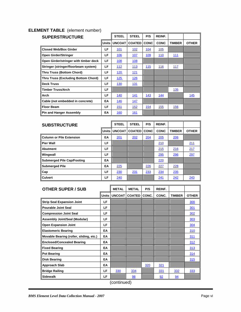
Concrete Deck and Concrete Slab - Elements ELEMENT DESCRIPTION 12 Concrete Deck - Bare - with Uncoated Reinforcement (EA)
No surface protection of any type and constructed with uncoated reinforcement bars. 13 Concrete Deck - with asphaltic concrete (AC) Overlay - w/o Membrane (EA)
No surface protection of any type and deck is covered with an (AC) overlay. 14 Concrete Deck - with AC Overlay - with Membrane (EA)
Decks protected with a membrane and the membrane is covered with (AC) overlay. 18 Concrete Deck - Thin Overlay (less than 1”) - no AC Overlay (EA)
Decks with a thin (<1”) overlay (portland cement, epoxy, resin, etc.) 22 Concrete Deck - Rigid Overlay (greater than 1”) - no AC Overlay (EA)
Decks with a rigid (>1”) overlay (low slump portland cement, epoxy, resin, etc.) 26 Concrete Deck - Bare - with Coated Reinforcement (EA)
Decks with coated (epoxy, galvanized, stainless steel, RFP, etc.) reinforcement bars. 27 Concrete Deck - with Cathodic Protection (EA) 38 Concrete Slab - Bare - with Uncoated Reinforcement (EA)
Slabs with no surface protection of any type and constructed with uncoated reinforcement bars.
39 Concrete Slab - with AC Overlay - w/o Membrane (EA) No surface protection of any type and the deck is covered with (AC) overlay.
40 Concrete Slab - with AC Overlay - with Membrane (EA) Slabs protected with a membrane and the membrane is covered with (AC) overlay.
44 Concrete Slab - Thin Overlay (less than 1”) - no AC Overlay (EA) Slabs with a thin (<1”) overlay (portland cement, epoxy, resin, etc.)
48 Concrete Slab - Rigid Overlay (greater than 1”) - no AC Overlay (EA) Slabs with a rigid (>1”) overlay (low slump portland cement, epoxy, resin, etc.)
52 Concrete Slab - Bare - with Coated Reinforcement (EA) Slabs with coated (epoxy, galvanized, stainless steel, RFP, etc.) reinforcement bars.
53 Concrete Slab - with Cathodic Protection (EA) Slabs protected with a cathodic system.
738VS Concrete Slab - Covered with Fill (EA) Slabs covered with fill.
NOTES: a) Any deck or slab that has an asphaltic overlay, even if it has coated reinforcement or a thin
or rigid overlay below the asphaltic overlay, shall be coded as Element no. 13 or 14 or Element no. 39 or 40.
b) A deck or slab with both uncoated and coated reinforcement bars shall be considered as a deck or slab with uncoated reinforcement.
c) Smart Flag 358 should only be used with Elements no. 12, 26, 27, 38, 52, or 53 (Concrete Decks or Slabs without overlays) and Elements no. 18, 22, 44 and 48 (Decks with thin/rigid overlays).
d) Concrete Frames - See the back of this manual for guidance on this type of structure. e) See the back of this manual for definitions and guidance on quantity.

BMS Element Level Data Collection Manual - 2007 Page 25
Concrete Deck and Concrete Slab - Condition States CONDITION STATE DESCRIPTIONS 1 This element exhibits no patched areas and/or deficiencies such as spalling,
delamination, etc. 2 Patched areas, spalling/delamination and/or potholes exist. Their combined area is
10% or less of the total deck area. 3 Patched areas, spalling/delamination and/or potholes exist. Their combined area is
more than 10% but 25% or less of the total deck area. 4 Patched areas, spalling/delamination and/or potholes exist. Their combined area is
more than 25% but less than 50% of the total deck area. 5 Patched areas, spalling/delamination and/or potholes exist. Their combined area is
50% or more of the total deck area. NOTES: a) When determining the correct condition state for a deck or slab, consider the condition of
both the top and the bottom of the element. Care must be taken when determining the percentage of the deck/slab affected. The inspector should not count overlapping areas of spalling/delamination and/or potholes on the top and the bottom twice.
b) The condition of the bottom of the deck or slab shall also be covered using the appropriate Smart Flag (359 and/or 707V).
c) If Element 738 is used its condition state shall be coded the same as the condition state for Smart Flag 359.
d) All known defects, whether visible or not, shall be counted; such as, known defects covered with an overlay or defects discovered as a result of a deck or slab evaluation.
e) Overlapping areas of patching, spalls/delamination of concrete or AC shall only be counted once.
f) Cracking of the top of the deck or slab shall also be covered using Smart Flag 358. g) A patched area will be considered a temporary fix for rideability such as an asphalt patch. A
repaired area will be considered a permanent fix. Patched areas cannot be returned to condition state 1. Repaired areas can be returned to condition state 1.
h) For decks that need to be replaced due to constant patching and/or repair also use Smart Flag 710.

BMS Element Level Data Collection Manual - 2007 Page 26
Metal Deck - Elements ELEMENT DESCRIPTION 28 Steel Deck - Open Grid (EA)
Decks that are constructed of steel grids that are open and unfilled. 29 Steel Deck - Concrete Filled Grid (EA)
Decks that are constructed of steel grids with either all of the openings or just those in the wheel tracks filled with concrete.
30 Metal Deck - Corrugated/Orthotropic, Etc. (EA) Decks that are constructed of corrugated metal filled with Portland Cement Concrete or asphaltic concrete or an orthotropic steel deck.
NOTES: a) Element 30 is NOT for decks designed with stay-in-place forms. It is intended for steel
corrugated decks with an asphalt or concrete riding surface. As a general rule, a stay-in-place form could be removed and the concrete deck would remain. If the metal deck is removed, and the riding surface would not remain, then it is appropriate to use this element.
b) See the back of this manual for definitions and guidance on quantity.

BMS Element Level Data Collection Manual - 2007 Page 27
Metal Deck - Condition States CONDITION STATE DESCRIPTIONS 1 No corrosion. Coating system, if any, is sound. Connectors (welds, rivets, etc.) are sound. Concrete filler is sound. Surfacing on a corrugated/orthotropic/etc. deck has no repaired areas or potholes. 2 Little or no corrosion. Coating system, if any, may be showing early signs of distress. Connectors are still sound. Concrete filler is sound. Potholes or minor cracking in surfacing of a corrugated/orthotropic/etc. deck. 3 Surface or freckled rust has formed. Coating system is no longer fully effective. No loss of section. Connectors starting to show signs of distress - cracked welds or broken rivets. Concrete filler may have broken out at scattered locations. Potholes and significant cracking in surfacing of a corrugated/orthotropic/etc. deck . 4 Corrosion is moderate. Surface pitting may be present but any section loss is incidental. Numerous connectors are failing at scattered locations. Section loss and/or connectivity are not sufficient to warrant structural analysis. Large potholes exist exposing metal decking of a corrugated/orthotropic/etc. deck. 5 Corrosion is advanced. Numerous connectors have failed. Section loss and/or connectivity are sufficient to warrant structural analysis. Much of the concrete filler is missing. Surfacing of a corrugated/orthotropic/etc. deck has failed.

BMS Element Level Data Collection Manual - 2007 Page 28
Timber Deck - Elements ELEMENT DESCRIPTION 31 Timber Deck - (EA)
Decks that are constructed of timber and are not overlaid. 32 Timber Deck - with asphaltic concrete (AC) Overlay (EA)
Includes timber decks that are constructed of timber and are overlaid with tar and gravel surface treatment.
54 Timber Slab - (EA) Slabs that are constructed of timber and are not overlaid.
55 Timber Slab - with asphaltic concrete (AC) Overlay (EA) NOTES: a) See the back of this manual for definitions and guidance on quantity.

BMS Element Level Data Collection Manual - 2007 Page 29
Timber Deck - Condition States CONDITION STATE DESCRIPTIONS 1 There is no decay. There may be cracks, splits and checks having no effect on
strength or the ability of this element to function as intended. The surfacing, if any, has no potholes.
2 Decay, insect infestation, splitting, cracking or crushing may exist but none is
sufficiently advanced to affect strength or the ability of this element to function as intended. If surfacing exists, there may be minor potholes or delamination of the surfacing.
3 Decay, insect infestation, splitting, cracking or crushing has produced loss of
strength or deflection of the element but is not sufficient to warrant structural analysis. If surfacing exists, there may be major potholes or delamination of the surfacing.
4 Advanced deterioration. Decay, insect infestation, splits, cracks or crushing has
produced loss of strength or deflection that is sufficient to warrant structural analysis.

BMS Element Level Data Collection Manual - 2007 Page 30
Culvert - Elements ELEMENT DESCRIPTION 240 Metal Culvert (LF along length of barrel)
Includes all metal (steel, aluminum, galvanized) culverts, including arches, round or elliptical pipes, etc.
241 Concrete Culvert (LF along length of barrel) Includes precast and cast-in-place (conventional or prestressed) concrete arch, pipe and box culverts.
242 Timber Culvert (LF along length of barrel) 243 Other Culvert (LF along length of barrel)
All culverts not included under steel, concrete or timber culverts. It will include masonry and combinations of other materials.
NOTES: a) Wing walls and headwalls/endwalls are not included in any culvert element but should be
coded separately. Smart Flags 298 (Culvert Endwall/Headwall) and 299 (Culvert Wingwall) may be applicable with any culvert element.
b) Smart flags for top and bottom of deck/slab cracking are not applicable for culverts. c) See the back of this manual for definitions and guidance on quantity.

BMS Element Level Data Collection Manual - 2007 Page 31
Culvert - Condition States CONDITION STATE DESCRIPTIONS 1 The element shows little or no deterioration. Only surface defects are evident. Some discoloration or surface corrosion may exist but there is no metal pitting. Little or no separation of joints or seams No misalignment problems are evident. Superficial cracks and spalls may be present, but there is no exposed reinforcing or
evidence of rebar corrosion. Timber and fasteners are in sound condition. 2 In metal culverts, corrosion and minor pitting may have begun especially in the invert. In timber culverts, corrosion at fasteners and connections may have begun. Deterioration, decay, weathering, minor chloride contamination, abrasion, cracking
and/or leaching may have begun. Little or no distortion and/or deflection exist. Minor separation of joints or seams. 3 In metal culverts, corrosion, deep pitting and/or some holes in the invert may exist. In timber culverts, significant decay, weathering and warped or broken timbers. In timber culverts, significant decay and corrosion at fasteners and connections may
be evident. Moderate to major deterioration, abrasion, extensive cracking and/or leaching and
large areas of spalls. Minor to moderate distortion, or misalignment may have occurred. Minor cracking or abrasion of the metal may exist. There may be considerable separation of joints or seams. 4 In metal culverts, corrosion, extreme pitting and/or holes in the barrel may exist. In timber culverts, major decay and many warped, broken or missing timbers exist. In timber culverts, major decay and corrosion at fasteners and connections exist. Major deterioration, abrasion, spalling, cracking, major distortion, deflection, or
misalignment of the barrel may be in evidence. Major cracking or abrasion of the metal may exist. Major separation of joints or seams may have occurred. Holes may exist in floors and walls.
Note: If there is settlement or tilt use Element 360 Settlement.

BMS Element Level Data Collection Manual - 2007 Page 32
Slope Protection - Elements and Condition States 285V Slope - Protected (EA) ELEMENT DESCRIPTION Slopes under a bridge that are protected by a erosion resistant material such as stone, concrete, masonry, timber, or some combination. CONDITION STATE DESCRIPTIONS 1 The slope shows little or no deterioration. 2 Minor cracks, spalls, splitting, settlement or joint deterioration may be present, but
there is no evidence of undermining of the protected slope. 3 Moderate deterioration of slope protection. Minor undermining and/or settlement may be present but erosion due to road run-off
is still controlled by slope protection. 4 Advanced deterioration (misalignment, crushing and/or settlement). Undermining of slope protection renders protection largely ineffective. NOTES: a) See the back of this manual for definitions and guidance on quantity.

BMS Element Level Data Collection Manual - 2007 Page 33
286V Slope - Unprotected (EA) ELEMENT DESCRIPTION Slopes under bridges that are NOT protected by an erosion resistant material. CONDITION STATE DESCRIPTIONS 1 The element shows little or no erosion. 2 Minor erosion may have occurred. There is no undermining or exposed piles. There has been no erosion that has exposed the bottom of the substructure elements. 3 Moderate erosion of slope is present but is incidental and does not adversely affect
the ability of this element to function as intended. The bottom of the substructure elements may be exposed for insignificant lengths
with no undermining or exposed piles. 4 Advanced erosion of slope is present and/or the slope has failed. The slope is no longer functioning as intended. The bottom of the substructure elements is exposed for significant lengths. Piles may be exposed. Substructure elements may be undermined. NOTES: a) See the back of this manual for definitions and guidance on quantity.

BMS Element Level Data Collection Manual - 2007 Page 34
Expansion Joint - Elements ELEMENT DESCRIPTION 300 Strip Seal Expansion Joint (LF)
Expansion joint devices that utilize a neoprene type waterproof gland with steel extrusion to anchor the gland. This element may be appropriate in cases where State Item 18 is coded “01 - Dam” in HTRIS.
301 Pourable Joint Seal (LF) Joints that have been sealed with a hot poured or a silicon sealer. This element may be appropriate in cases where State Item 18 is coded “05 - Strip Sealer” or “07 -- Dow Corning 902” in HTRIS.
302 Compression Joint Seal (LF) Joints filled with a pre-formed compression type seal. This element may be appropriate in cases where State Item 18 is coded “04 - Compression Sealer” in HTRIS.
303 Assembly Joint/Seal (LF) Joints filled with an assembly mechanism that may or may not have a seal. Use this element for all sliding plate roadway devices and modular joints. This element may be appropriate in cases where State Item 18 is coded “02 - Tooth Joint” or “03 - Sliding Plate” in HTRIS.
304 Open Expansion Joint (LF) Joints that are open and not sealed and were not designed to be waterproof. This element may be appropriate in cases where State Item 18 is coded “06 - Armored Joint” in HTRIS.
NOTES: a) Approach slab expansion joints are included in these elements. b) If the joint seal material is missing code the joint element according to the original material
and place in Condition State 3.

BMS Element Level Data Collection Manual - 2007 Page 35
Expansion Joint - Condition States CONDITION STATE DESCRIPTIONS 1 The element shows minimal deterioration. The seal shows no leakage at any point along the joint. Gland is secure and has no defects. Debris in joint is not causing any problems. The adjacent deck and/or header are sound. The armored joint anchorage shows no signs of looseness. Fingers are not broken or misaligned. Welds exhibit no problems. The coating system is functioning as intended. 2 The element shows moderate deterioration and/or minor cohesion failures. The seal shows signs of leakage along the joint. Gland shows signs of abrasion or minor tearing or is partially pulled out of the
extrusion. Significant debris is in all or part of the joint and is affecting joint performance. The adjacent deck and/or header exhibit no spalls. The armored joint anchorage is loose. Fingers are bent or misaligned. Welds exhibit minor cracking. The coating system is beginning to fail with the element beginning to corrode. 3 The element has failed. The seal shows signs of leakage along the joint. Gland has failed from abrasion or tearing or has pulled out of the extrusion. The adjacent deck and/or header exhibit spalls. The armored joint anchorage has failed. Fingers are missing or broken. Welds are failing. The coating system has failed with the element exhibiting advanced corrosion. NOTES: a) See the back of this manual for definitions and guidance on quantity. b) If the joint seal material is completely missing, place in Condition State 2 or 3 depending on
the condition of the adjacent deck and/or header and code the joint element according to the original material.
c) Evidence of mechanism failure such as loose or broken springs, bolts, or support bars shall be coded as Condition State 3.

BMS Element Level Data Collection Manual - 2007 Page 36
Bearing - Elements ELEMENT DESCRIPTION 310 Elastomeric Bearing (EA)
Expansion bridge bearings that are constructed primarily of elastomers, with or without fabric or metal reinforcement.
311 Moveable Bearing (Roller, sliding, etc.) (EA) 312 Enclosed/Concealed Bearing or Bearing System (EA)
Bridge bearings that are enclosed so that they are not open for detailed inspection. 313 Fixed Bearing (EA)
Bridge bearings that provide for deflection and do not allow for longitudinal movement.
314 Pot Bearing (EA) High load bearings with confined elastomer. The bearing may be fixed against horizontal movement, guided to allow movement in one direction, or floating to allow sliding in any direction.
315 Disk Bearing (EA) High load bearings with a hard plastic disk. The bearing may be fixed against horizontal movement, guided to allow movement in one direction, or floating to allow sliding in any direction.
NOTES: a) If it cannot be determined if a bearing is fixed or expansion, it should be coded as an
expansion bearing until a correct determination can be made. b) Element 310 (Elastomeric Bearing) is for expansion bearings. If the bearing is constructed
to prevent thermal movement, it should not be coded as an elastomeric bearing. In some cases, small elastomeric pads (less than 0.5” thick) are used with fixed bearings. In these cases, the elastomeric pad should be ignored and the bearing coded as Element 313 - (Fixed Bearing).
c) Element 313 (Fixed Bearing) includes those fixed bearings with small elastomeric pads (usually less than 0.5” thick).

BMS Element Level Data Collection Manual - 2007 Page 37
Bearing - Condition States CONDITION STATE DESCRIPTIONS 1 The element shows little or no deterioration and has minimal debris and corrosion. The coating system, if present, is sound and functioning as intended. Vertical and horizontal alignments are within limits. For elastomeric bearings the
vertical slope is 0 - 30 degrees. Bearing support member is sound. There is no cracking of support members. Any lubrication system is functioning properly. The supported member is stable under traffic. 2 The coating system, if present, has failed and exposed metal may show moderate to
heavy corrosion with some pitting but still functioning as intended. The assemblies have moved causing minor cracking in the supporting concrete. Debris buildup is affecting bearing movement. Bearing alignment and/or load carrying capacity is still tolerable. FOR ELASTOMERIC BEARINGS Minor cracking, splitting or other deterioration may be present. Shear deformation may be slightly excessive. Strength and/or the ability of this element to function as intended are not affected (the
vertical slope is 30 - 45 degrees.) FOR ENCLOSED/CONCEALED BEARINGS OR BEARING SYSTEMS. Both vertical and horizontal offsets are within the capability of the bearings. The supported member may exhibit minimal vertical movement under traffic. Cracking of support members is not yet significant. There may be insignificant reduction of bearing due to superstructure shortening. 3 Section loss sufficient to warrant supplemental supports or load restrictions. Bearing alignment may be beyond tolerable limits. Shear keys and the lubrication system, if any, may have failed. FOR ELASTOMERIC BEARINGS Shear deformations may be excessive. Top and bottom surfaces may no longer be parallel. Loss of bearing may be imminent. (The vertical slope is greater than 45 degrees.) FOR ENCLOSED/CONCEALED BEARINGS OR BEARING SYSTEMS. Vertical and/or horizontal offsets are significant indicating bearing failures. There may be significant vertical movement under traffic. Cracking of the support members may be significant. There may be significant reduction of bearing due to superstructure shortening. FOR POT BEARINGS Elastomer may be actively extruding from the device. NOTES: a) See the back of this manual for definitions and guidance on quantity.

BMS Element Level Data Collection Manual - 2007 Page 38
Approach Slab – Elements and Condition States 320 Prestressed Concrete Approach Slab (EA) 321 Reinforced Concrete Approach Slab (EA) ELEMENT DESCRIPTION None CONDITION STATE DESCRIPTIONS 1 The slab has not settled and shows no sign of deterioration other than superficial
surface cracks. 2 Minor cracking, spalls may be present but they do not affect the ability of the slab to
carry traffic. Settlement may be occurring which increases the traffic impact on the bridge. 3 Cracks may extend completely through the slab cross-section, but the slab does not
act as if it is broken. Spalls may be heavy but they do not affect the structural integrity of the slab. Settlement may be occurring which increases the traffic impact on the bridge. 4 The slab is broken or rocks under traffic loads. Settlement is excessive and cannot be corrected without increasing the size of the
slab. NOTES:

BMS Element Level Data Collection Manual - 2007 Page 39 Modified 3-5-2008
Smart Flags ELEMENT DESCRIPTION 298V Culvert Endwall/Headwall (EA)
To be used for endwalls/headwalls of any material. If there is settlement or tilt use Element 360 Settlement.
299V Culvert Wingwall (EA) To be used for wingwalls of any material. If there is settlement or tilt use Element 360 Settlement
356 Steel Fatigue (EA) This should not be applied until fatigue damage to steel becomes apparent.
357 Pack Rust (EA) Use for rust packing in connections and built-up steel members. This Smart Flag should not be used for corrosion of the top flange.
358 Deck Cracking (EA) Use for concrete deck/slab elements that exhibit cracking on the top of deck/slab. This Smart Flag is to be used only with Elements no. 12, 18, 22, 26, 27, 38, 44, 48, 52, or 53 (Concrete Decks or Slabs without asphaltic overlays).
359 Soffit of Concrete Decks/Slabs (EA) Represents entire soffit of a deck/slab, not the soffit of an overhang. For undersurface of overhang use Smart Flag 706V.
360 Settlement (EA) Use when the substructure exhibits any distress due to settlement.
361 Scour (EA) Use for scour/undermining evident during inspections of any structure including culverts and pipes.
362 Traffic Impact Damage (EA) This flag should be used for superstructure impact damage.
363 Section Loss (EA) This flag should be used when a steel element reaches condition state 4 or for elements that have section loss that has been cleaned and painted over. This flag should be used for both coated and uncoated elements.
701V Utilities (EA) Use for utilities mounted to the structure. Groups of similar utilities in the same assembly and performing the same function should be evaluated as one utility. For dissimilar utilities, use a separate smart flag for each dissimilar utility.
702V Drains (EA) Does not apply to drainage off the end of a bridge. The quantity will always be one, even if there are dissimilar drainage types.
703V Lighting (EA) The quantity will always be one, even if there are dissimilar lighting types.
704V Roadway Over Culverts (EA)
(continued)

BMS Element Level Data Collection Manual - 2007 Page 40
Smart Flags ELEMENT DESCRIPTION (continued) 706V Soffit of Overhang of Concrete Decks/Slabs (EA)
Represents the entire undersurface of the overhang. For slabs this will be approximately the first 1 foot of the bottom of the slab measured from the exterior edge of the deck. For undersurface of decks/slabs use Smart Flag 359.
707V Soffit of Concrete Decks/Slabs with SIP Forms (EA) Represents entire soffit of a deck/slab, not the soffit of an overhang. For undersurface of overhang use Smart Flag 706.
708V Debris in Channel (EA) This smart flag is used for classifying debris (sediment, vegetation, trash, etc.) restricting the channel under a structure.
709V Structure Replacement (EA) This smart flag is used to indicate those structures where it would be practical to replace the structure rather than repair the structure. The only money that should be spent on this type of structure would be for repairs that protect the safety of the traveling public.
710V Deck Replacement (EA) This smart flag is used to indicate those structures where it would be practical to replace the deck even though patching and/or repair of the deck have continued to keep the condition state of the deck at a ‘1’.
NOTES: a) The quantity for each Smart Flag will always be one (1) and will represent all occurrences of
that Smart Flag on the bridge. Unless otherwise stated, do not count each occurrence of an individual Smart Flag separately.
b) See the back of this manual for definitions and guidance on coding ‘Steel Diaphragms/Cross Frames’ that are a part of a curved girder system.

BMS Element Level Data Collection Manual - 2007 Page 41
Smart Flags - Condition States 298V Culvert Endwall/Headwall (EA)
CONDITION STATE DESCRIPTIONS 1 Little or no deterioration/decay.
There may be superficial defects such as discoloration, efflorescence, surface rust and/or superficial cracking without affect on strength and/or ability to function as intended.
2 Minor deterioration.
Minor deterioration, cracking, corrosion, decay and weathering may exist but none is sufficiently advanced to affect strength of the element or the ability of the element to function as intended.
Spalling may be present but there is no exposed reinforcing or surface evidence of rebar corrosion.
Minor insect/marine borer infestation, crushing, checking, splitting or other defect may exist.
Joints may show minor deterioration or separation. Some movement (i.e. sliding) or bulging may have occurred with little or no affect
on the slope or fill. 3 Moderate deterioration.
Moderate to major deterioration cracking, section loss due to corrosion, decay and/or weathering or other defect exists but does not warrant structural analysis.
Decay, insect/marine borer infestation, crushing or other defect may have produced some loss of strength or deflection.
Some delaminations and/or spalls may be present and some reinforcing may be exposed.
Corrosion of rebar may be present. Major deterioration of joints may be causing individual elements (rocks, bricks, bagged riprap, etc.) to be loose. Some movement (i.e. sliding) has occurred and the stability of the slope is being compromised. Some fill may have washed from behind headwall/endwall(s). There may be signs of bulging, and some fill may have seeped through.
4 Advanced deterioration. Major deterioration, splitting, cracking, corrosion, holes, loss of section, decay
and/or weathering or other defect has produced loss of strength that is sufficient to warrant structural analysis.
Significant movement (i.e. sliding) has occurred and the stability of the slope or the headwall/endwall is compromised.
Decay, insect/marine borer infestation, crushing or other defect has produced loss of strength or deflection.
Individual elements are missing/collapsed leaving voids. Bulging may be advanced.

BMS Element Level Data Collection Manual - 2007 Page 42
299V Culvert Wingwall (EA)
CONDITION STATE DESCRIPTIONS 1 Little or no deterioration/decay.
There may be superficial defects such as discoloration, efflorescence, surface rust and/or superficial cracking without affect on strength and/or ability to function as intended.
2 Minor deterioration.
Minor deterioration, cracking, corrosion, decay and weathering may exist but none is sufficiently advanced to affect strength of the element or the ability of the element to function as intended.
Spalling may be present but there is no exposed reinforcing or surface evidence of rebar corrosion.
Minor insect/marine borer infestation, crushing, checking, splitting or other defect may exist.
Joints may show minor deterioration or separation. Some movement (i.e. sliding or tilting) or bulging may have occurred with little or
no affect on the slope or fill. 3 Moderate deterioration.
Moderate to major deterioration cracking, section loss due to corrosion, decay and/or weathering or other defect exists but does not warrant structural analysis.
Decay, insect/marine borer infestation, crushing or other defect may have produced some loss of strength or deflection.
Some delaminations and/or spalls may be present and some reinforcing may be exposed.
Corrosion of rebar may be present. Major deterioration of joints may be causing individual elements (rocks, bricks, bagged riprap, etc.) to be loose. Some movement (i.e. sliding or tilting) has occurred and the stability of the slope is being compromised. Some fill may have washed from behind wingwall(s). There may be signs of bulging, and some fill may have seeped through.
4 Advanced deterioration. Major deterioration, splitting, cracking, corrosion, holes, loss of section, decay
and/or weathering or other defect has produced loss of strength that is sufficient to warrant structural analysis.
Significant movement (i.e. sliding or tilting) has occurred and the stability of the slope or the wingwall is compromised.
Decay, insect/marine borer infestation, crushing or other defect has produced loss of strength or deflection.
Individual elements are missing/collapsed leaving voids. Bulging may be advanced.
BMS Element Level Data Collection Manual - 2007 Page 43
356 Steel Fatigue (EA)
CONDITION STATE DESCRIPTIONS
1 Fatigue damage to the bridge has been repaired or arrested. The bridge may still be fatigue prone.
2 Fatigue damage exists which is not arrested. 3 Fatigue damage exists which is sufficient to warrant structural analysis.
357 Pack Rust (EA)
CONDITION STATE DESCRIPTIONS
1 The connection is showing signs of rusting between the plates. Seams of the connections exhibit rust staining. No swelling exists.
2 Rusting between plates is beginning to distress the connection.
Minor swelling exists. 3 Rusting between plates has caused serious distress to the connection.
The plates may be badly distorted, however all connectors (rivets/bolts) are still functioning.
4 Rusting between plates has caused serious distress to the connection sufficient
to warrant structural analysis. Some rivets or other connectors may have popped or are no longer effective.

BMS Element Level Data Collection Manual - 2007 Page 44
358 Deck Cracking (EA)
CONDITION STATE DESCRIPTIONS
1 The surface of the deck is cracked, but the cracks are either filled/sealed or insignificant in size and density (cracks less than 1/16 inch in width and spaced greater than 10 feet apart).
2 Unsealed cracks exist which are of moderate size OR density (cracks greater than
or equal to 1/16 inch and less than 3/16 inch in width OR where cracks are spaced 5 feet to 10 feet apart).
3 Unsealed cracks exist in the deck that are of moderate size AND density (cracks
greater than or equal to 1/16 inch and less than 3/16 inch in width AND where cracks are spaced 5 feet to 10 feet apart).
4 Unsealed cracks exist in the deck that are of severe size AND/OR density (cracks
greater than 3/16 inch in width AND/OR are spaced less than 5 feet apart).
359 Soffit of Concrete Decks/Slabs (EA)
CONDITION STATE DESCRIPTIONS
1 There are little or no symptoms of distress and any cracking or efflorescence is less than 2% of the total underside area.
2 Cracking and/or efflorescence is light any the combined distressed area is 2% to
10% of the soffit. 3 Moderate efflorescence and/or cracking (cracks greater than or equal to 1/16 inch
and less than 3/16 inch in width OR where cracks are spaced 5 feet to 10 feet apart) and the combined distressed area is greater than 10% but 25% or less of the soffit.
4 Light to moderate rust staining and/or delamination/spalling and heavy cracking
(cracks greater than or equal to 1/16 inch and less than 3/16 inch in width AND where cracks are spaced 5 feet to 10 feet apart) and/or efflorescence and the combined distressed area is more than 25% but less than 50% of the soffit.
5 Heavy to severe rust staining and/or delamination/spalling and severe cracking
(cracks greater than 3/16 inch in width AND/OR are spaced less than 5 feet apart) and/or efflorescence and the combined distressed area is 50% or more of the soffit.

BMS Element Level Data Collection Manual - 2007 Page 45
360 Settlement (EA)
CONDITION STATE DESCRIPTIONS
1 Some of the bridge supporting or culvert elements are showing signs of visible settlement or rotation but due to earlier repairs or other signs, the settlement appears to have stabilized.
2 Settlement or rotation of the bridge supporting or culvert elements shows signs
of continuing and if left unarrested could cause adverse impacts to the bridge. 3 Settlement or rotation of the bridge supporting or culvert elements is sufficient to
warrant structural analysis.
361 Scour (EA)
CONDITION STATE DESCRIPTIONS
1 Scour exists at the bridge or culvert site but is of little concern to the structural integrity of the bridge or culvert.
2 Scour exists at the bridge or culvert site and if left unchecked could adversely
impact the structural integrity of the bridge or culvert. 3 Scour is significant enough to warrant analysis of the bridge or culvert.
NOTES: a) Substructure elements should not be assigned a lower condition state because of scour.

BMS Element Level Data Collection Manual - 2007 Page 46
362 Traffic Impact Damage (EA)
CONDITION STATE DESCRIPTIONS 1 Impact damage has occurred and has been repaired.
Prestressing system is covered by patch concrete. Steel has been straightened or repaired.
2 Impact damage has occurred.
Prestressing system is exposed, but is not impaired. Steel condition does not threaten the ability of the bridge to function as intended.
3 Impact damage has occurred and strength of the member is impaired.
Impact damage is sufficient to warrant structural analysis.
363 Section Loss (EA)
CONDITION STATE DESCRIPTIONS
1 Section loss has been repaired or cleaned and coated over. 2 Section loss exists and has not been repaired or coated over. Structural analysis
is not yet warranted. 3 Section loss exists which is sufficient to warrant structural analysis or an analysis
has determined that the ability of the bridge to function as intended has not been affected i.e. there is no reduction in the posted capacity or a non-posted structure does not require posting.
4 Section loss has affected the load carrying capacity or the ability of the bridge to
function as intended i.e. there is a reduction in the posted capacity. (Code this condition state only after a structural analysis.)

BMS Element Level Data Collection Manual - 2007 Page 47
701V Utilities (EA)
CONDITION STATE DESCRIPTIONS
1 The supporting elements, and their attachment to the structure, are in good condition and functioning as designed. There is little or no deterioration of the supports, attachments, or the utility itself.
2 The supporting elements, and their attachment to the structure, are in sound
condition and functioning as designed. There are signs of deterioration (e.g., flaking coating, active corrosion), and the utility may have loose joints but no exposed wires or leaks.
3 The supporting elements or their attachments to the structure shows signs of
active deterioration (e.g., some section loss, breakdown of protective coating). Some supporting elements may be loose or missing, but the utility is adequately supported. The utility may have cracks in the conduit or joints exposing wires or allowing leaks not affecting the superstructure or substructure elements and not affecting the safety of the public.
4 The supporting elements or their attachments to the structure show advanced
deterioration with supporting elements loose or missing. The utility sags or moves freely and support is no longer adequate. Sections of the conduit are broken or missing, allowing access to the wires or major (or numerous) leaks. Wires may be accessible to the public, leaks may be onto roadways, pedestrian trails, or affect the superstructure, substructure, or the slope.

BMS Element Level Data Collection Manual - 2007 Page 48
702V Drains (EA)
CONDITION STATE DESCRIPTIONS
1 Grating over scuppers or drains is intact and is functioning as intended. Bridge drainage and/or down spouting is adequately terminated. No signs of ponding occurring on the deck as a result of drainage problems.
2 Scuppers and/or downspouts are clogged, however, there are no signs of
ponding on the deck. Down spouting is inadequately terminated.
3 Scuppers and/or downspouts are clogged and there are signs of ponding on the
deck but does not extend into the normal traffic lane. 4 Broken or missing grates/drainage assembly may pose a hazard to vehicular or
pedestrian traffic. Scuppers and/or downspouts are clogged and there are signs of ponding on the deck that extends into the normal traffic lane.
NOTES: a) If more than one condition problem exists assign the worst condition state. For example:
Down spouting is inadequately terminated (condition state 2) and clogged drains cause ponding on the deck (condition state 3). For this example assign condition state 3.

BMS Element Level Data Collection Manual - 2007 Page 49
703V Lighting (EA)
CONDITION STATE DESCRIPTIONS
1 Lighting standards and supports are properly anchored. There are no indications of fatigue damage. There are no missing or broken luminares or exposed wires.
2 Lighting standards and supports are properly anchored. There are no indications of fatigue damage. There may be some missing or broken luminares, but there are no exposed wires.
3 Lighting standards and supports are properly anchored. There may be some indications of fatigue damage. Luminares may be missing or broken, but there are no exposed wires.
4 Lighting standards and supports may be improperly anchored. There may be indications of fatigue damage. Luminares may be missing or broken, or there may be exposed wires.

BMS Element Level Data Collection Manual - 2007 Page 50
704V Roadway Over Culverts (EA)
CONDITION STATE DESCRIPTIONS
1 The roadway over the culvert is smooth. No indication of settlement.
2 Roadway shows minor signs of deterioration (e.g., cracking).
The roadway over the culvert is settled however no reduction in speed is required to safely negotiate this section of roadway over the culvert.
3 The roadway over the culvert is significantly deteriorated and/or the roadway over
the culvert is settled and a minor reduction in speed is required to safely negotiate this section of roadway over the culvert.
4 Roadway may have cracks, voids, and areas of erosion that may pose a traffic
hazard and/or the roadway over the culvert is settled and a substantial reduction in speed is required to safely negotiate this section of roadway over the culvert.

BMS Element Level Data Collection Manual - 2007 Page 51
706V Soffit of Overhang of Concrete Decks/Slabs (EA)
CONDITION STATE DESCRIPTIONS
1 There are little or no symptoms of distress.
2 Cracking and/or efflorescence is light.
3 Cracking and/or efflorescence are moderate (cracks greater than or equal to 1/16 inch and less than 3/16 inch in width OR where cracks are spaced 5 feet to 10 feet apart).
4 Light to moderate rust staining and/or delamination/spalling and/or heavy
cracking and/or efflorescence (cracks greater than or equal to 1/16 inch and less than 3/16 inch in width AND where cracks are spaced 5 feet to 10 feet apart).
5 Heavy to severe rust staining and/or delamination/spalling and/or severe cracking
and/or efflorescence (cracks greater than 3/16 inch in width AND/OR are spaced less than 5 feet apart).

BMS Element Level Data Collection Manual - 2007 Page 52
707V Soffit of Concrete Decks/Slabs with SIP Forms (EA)
CONDITION STATE DESCRIPTIONS
1 There are no symptoms of distress.
2 Any evidence of moisture or efflorescence is minor and widely scattered. Metal Forms - surface or spot rust is present. Concrete Forms - there may be minor hairline cracks.
3 Moisture and efflorescence are present at the construction joints.
Rust stains can be attributed to corrosion of deck reinforcing. Metal Forms - severe rust with pitting or minor section loss. Concrete Forms - cracks are greater than hairline with moisture, efflorescence, and/or rust stains.
4 There are areas of spalling and/or cracks, with rust stains that can be attributed to
deck reinforcing. Metal Forms - Corrosion is advanced. Some forms may have holes, be loose, or missing (because of deterioration). Concrete Forms - have open cracks with delaminations/spalls. Moisture and efflorescence is heavy and widespread at the joints. The combined distressed area is greater than 10% but 25% or less of the soffit.
5 Metal Forms - have failed, exposing the bottom of the deck.
Concrete Forms - have spalls for full depth of forms and exposed reinforcing may have severe rust with measurable section loss. The bottom of the deck has delaminations/spalls with exposed deck reinforcing. The combined distressed area is greater than 25% of the soffit.

BMS Element Level Data Collection Manual - 2007 Page 53
708V Debris in Channel (EA)
CONDITION STATE DESCRIPTIONS
1 Minor amount of debris in channel. Less than 10% of the opening is blocked. Debris is not detrimental to the structure and no action is required.
2 Moderate amount of debris in channel. 10% to 25% of the opening is blocked. Debris is not detrimental to the structure but should be removed as soon as practicable to prevent damage/additional accumulation.
3 Large amount of debris in the channel. More than 25% of the opening is blocked. Debris is detrimental to the structure (causing excessive drag forces, turbulence near substructure units, redirecting flow to substructures and/or embankments, etc.) and should be removed right away.
709V Structure Replacement (EA)
CONDITION STATE DESCRIPTIONS
1 Engineering analysis (see below) indicates replacement is the most economical action for the structure. However, if funding is constrained, maintenance on the structure is still feasible.
2 Bridge is scheduled for replacement within an improvement plan but the ad date
is greater than 24 months out. 3 Bridge is scheduled for major rehabilitation or replacement within the next 24
months.
4 Engineering analysis confirms the structure is “non-maintainable”. Maintenance of the existing structure is not practical with the only feasible actions being replacement or closure.
NOTES: a) The smart flag is only to be used as directed by the district person directly responsible for
Bridge Management. b) Analysis shall be documented and maintained for future reference within the Bridge
Management System.

BMS Element Level Data Collection Manual - 2007 Page 54
710V Deck Replacement (EA)
CONDITION STATE DESCRIPTIONS
1 Patched/repaired areas, spalling/delamination and/or potholes exist. Their combined area is 25% or less of the total deck area. The deck soffit exhibits moderate efflorescence and/or cracking and the combined distressed area is less than 25% of the soffit area.
2 Patched/repaired areas, spalling/delamination and/or potholes exist. Their
combined area is more than 25% but less than 50% of the total deck area. The deck soffit exhibits light to moderate discoloration and/or delamination/spalling and heavy cracking and/or efflorescence and the combined distressed area is more than 25% but less than 50% of the soffit area.
3 Patched/repaired areas, spalling/delamination and/or potholes exist. Their
combined area is 50% or more of the total deck area. The deck soffit exhibits heavy to severe discoloration and/or delamination/spalling and severe cracking and/or map-cracking and/or efflorescence and the combined distressed area is 50% or more of the soffit area. Deck should be replaced rather than repaired.
4 Engineering analysis indicates that deck should be replaced rather than repaired.
NOTES: a) The smart flag is only to be used as directed by the district person directly responsible for
Bridge Management. b) To determine the correct condition state for a deck, consider the condition of both the top
and the bottom of the element. Care must be taken when determining the percentage area of the deck affected. Do not count overlapping areas of patches/repairs, spalling/delamination and/or potholes on the top and/or the bottom twice.
c) All known defects, whether visible or not, shall be counted such as known defects covered with an overlay or defects discovered as a result of a deck or slab evaluation.
d) Cracking of the top of the deck shall also be covered using Smart Flag 358. e) Engineering analysis noted in Condition state ‘4’ shall be documented and maintained for
future reference within the Bridge Management System.
BMS Element Level Data Collection Manual - 2007 Page 55
DEFINITIONS AND GUIDANCE FOR DETERMINING ELEMENTS AND QUANTITIES
GENERAL NOTES Certain elements should be coded regardless of condition. Examples are (but are not limited to):
• Smart Flag 359 (soffit) • Element 701 (utilities) • Element 702 (drains) • Element 703 (lighting) • Smart Flag 704 (roadway over culvert) • Smart Flag 706 (underside of overhang) • Smart Flag 707 (soffit with sip) • Element 738 (slab covered with fill)
Any item placed to provide support until permanent repairs can be made is not to be entered into Pontis. This includes but is not limited to steel or timber bents. When backwalls or bearing seats consist of a material different from the primary material of the substructure unit, the condition of the backwall or the bearing seat will not be tracked using a Pontis element or smart flag. FOOTBRIDGES AND PEDESTRIAN BRIDGES Footbridges and Pedestrian bridges will be placed in Pontis and NBI ratings are required. However, no elements for either type of structure are required. If the structure can be modeled using Pontis elements the district can elect to place elements in Pontis and treat them as Non-Element inspections. DECK ELEMENTS The quantity for all deck elements are measured in square feet. However, the entire quantity can only be placed in one condition state. Deck Area
Deck area shall be calculate based on the out-to-out width of the slab and the total length of the bridge (back-to-back of backwalls or end-to-end of slab)
Decks and Slabs
Deck Elements and Slab Elements are defined separately. Care should be taken to define these elements correctly. Slab Elements are stand-alone structures such as slab spans. Primary structural members, such as steel beams or prestressed beams, support Deck Elements.
Decks - Multiple
A bridge may be composed of several deck elements i.e. Element 12 - Concrete Deck (Bare) and Element 28 - Steel Deck, Open Grid. For this example, both elements shall

BMS Element Level Data Collection Manual - 2007 Page 56
be coded and the entire quantity for each deck element shall be placed in one condition state.
SUPERSTRUCTURE ELEMENTS Determining quantities
This convention applies to all girders, channels, and box girders. The quantity is NOT dependent on the number of visible pairs of girder faces but is determined by the length of the bridge multiplied by the number of girders, beams, channels or box girders.
Example 1: Reinforced Channels (Adjacent)
Since there are three (3) channel beams, the quantity should be the length of the bridge multiplied by 3. For the above figure a bridge that is 25 feet in length and 30 feet wide, the total girder quantity should be 75 feet.
Element # Element Name Quantity 110 Reinforced Concrete Open Girder/Stringer 75 LF (3 X 25) 12 Concrete Deck - Bare (EA) 750 SF (30 x 25)
321

BMS Element Level Data Collection Manual - 2007 Page 57
Example 2: Reinforced Channels (Spread)
Since there are three (3) channel beams, the quantity should be the length of the bridge multiplied by 3. For the above figure a bridge that is 25 feet in length and 30 feet wide, the total girder quantity should be 75 feet.
Element # Element Name Quantity 110 Reinforced Concrete Open Girder/Stringer 75 LF (3 X 25) 12 Concrete Deck - Bare (EA) 750 SF (30 x 25)
Example 3: Cast-in-Place Concrete Multi-cell Box Girders
Elements for both the girder and the deck are necessary, even though the unit is integral. A multi-cell box girder is considered to be one girder. For the above figure a bridge that is 25 feet in length and 30 feet wide, the total girder quantity should be 25 feet.
Element # Element Name Quantity 105 Reinforced Concrete Closed Web/Box Girder 25 LF (1 X 25) 12 Concrete Deck - Bare (EA) 750 SF (30 x 25)
2 3 1

BMS Element Level Data Collection Manual - 2007 Page 58
Example 4: Cast-in-Place Concrete Tee Beam
Elements for both the girder and the deck are necessary, even though the unit is integral. The quantity is the length of the bridge multiplied by 4. For the above figure a bridge that is 25 feet in length and 30 feet wide, the total girder quantity should be 100 feet.
Element # Element Name Quantity 110 Reinforced Concrete Open Girder/Stringer 100 LF (4 X 25) 12 Concrete Deck - Bare (EA) 750 SF (30 x 25)
1 32 4
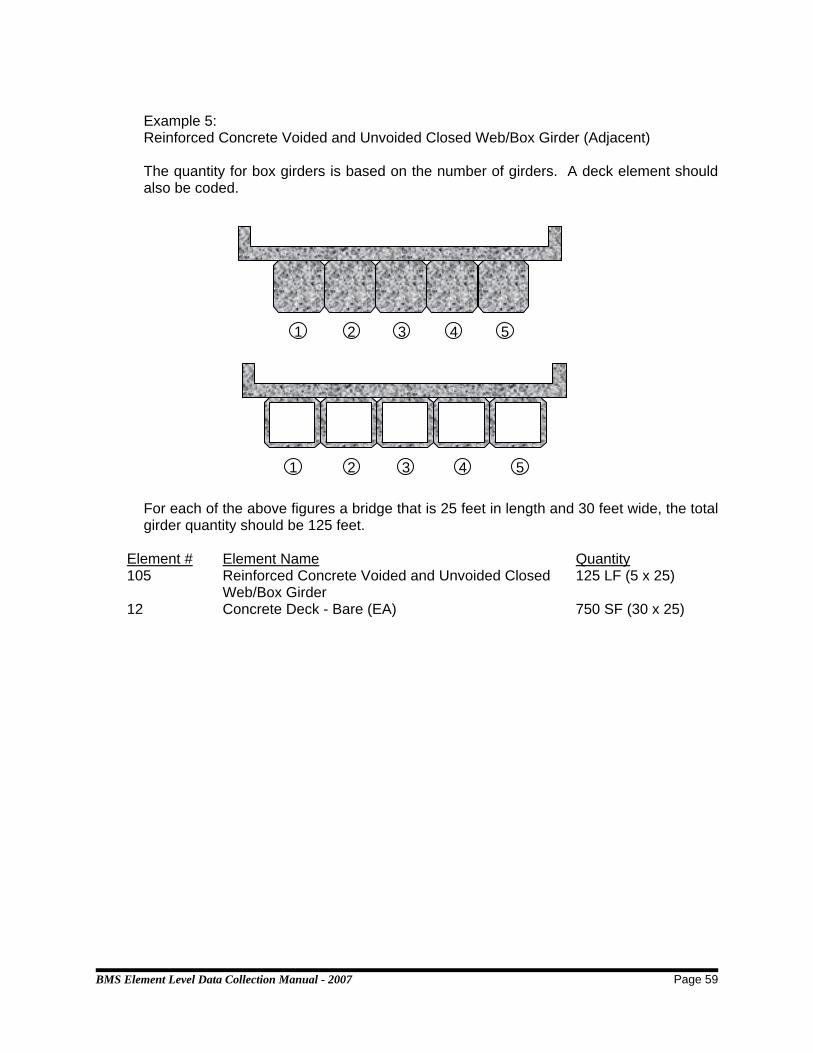
BMS Element Level Data Collection Manual - 2007 Page 59
Example 5: Reinforced Concrete Voided and Unvoided Closed Web/Box Girder (Adjacent) The quantity for box girders is based on the number of girders. A deck element should also be coded.
For each of the above figures a bridge that is 25 feet in length and 30 feet wide, the total girder quantity should be 125 feet.
Element # Element Name Quantity 105 Reinforced Concrete Voided and Unvoided Closed
Web/Box Girder 125 LF (5 x 25)
12 Concrete Deck - Bare (EA) 750 SF (30 x 25)
1 2 3 4 5
1 2 3 4 5

BMS Element Level Data Collection Manual - 2007 Page 60
Example 6: Reinforced Concrete Voided and Unvoided Closed Web/Box Girder (Spread)
The quantity should be the length of the bridge multiplied by 3. For the above a bridge that is 25 feet in length and 30 feet wide, the total girder quantity should be 75 feet.
Element # Element Name Quantity 105 Reinforced Concrete Voided and Unvoided
Closed Web/Box Girder 75 LF (3 X 25)
12 Concrete Deck - Bare (EA) 750 SF (30 x 25)
Example 7: Stringers/Floor Beams/Girders The figure below shows a two-girder bridge that is 50 feet long with three floorbeams that are 25 feet long each and five stringers.
Element # Element Name Quantity 107 Steel Open Girder - Coated 100 LF (2 x 50) 113 Steel Stringer - Coated 250 LF (5 x 50) 152 Steel Floor Beam - Coated 75 LF (3 x 25)
Stringer Floorbeam
Girder
25 feet
2 31
2 31

BMS Element Level Data Collection Manual - 2007 Page 61
Example 8: Steel Diaphragms/Cross Frames that are a part of a curved girder system. Steel diaphragms or steel cross frames are primary structural members when they are part of a curved girder system. Therefore, the length of these members must be captured as shown below.
Element # Element Name Quantity 107 Steel Open Girder - Coated 380 LF (3 x 100) + (10 x 8)
SUBSTRUCTURE ELEMENTS
Abutments - General
For the purposes of element-level inspections, the condition of backwall, bearing seats, breast wall, weep holes, and footings are to be considered as a part of the abutment. Gravity abutments should be coded as reinforced concrete abutments. Wingwalls - Non-Integral and Integral
Wingwalls should not be included with substructure/culvert elements regardless of being integral or non-integral with the substructure/culvert element. Wing length will be measured beginning at the wing tip and ending at one of the following locations:
• first vertical joint adjacent to the substructure/culvert proper • break of the wing • edge of the deck slab
In cases where more than one of the above locations is present on a substructure/culvert element the measurement of the wing shall be made beginning at
2 spaces @ 8 feet each
Each Girder = 100 feet
Curved Girder (typ)
Steel Diaphragm (typ)

BMS Element Level Data Collection Manual - 2007 Page 62
the wing tip and ending at the first location reached in the order of the locations shown above.
Timber Abutments/Bents/Piers/Pile Bents, Etc. General The condition of all diagonal/cross bracing on substructure units should be considered in rating the condition of the appropriate substructure unit (columns, piles, etc.). In the event that the bracing is deteriorated, deteriorated section of bracing should be considered to be part of the nearest appropriate substructure unit (columns, piles, etc.). Considering the Timber Bent shown below, if there was no decay of the piles, but there was decay of the cross bracing with no loss of strength or indication of deflection, then the element ‘Timber Column or Pile Extension’ should be placed in condition state 2. Timber abutments are typically coded as 3 different elements: a timber cap, timber columns, and a timber abutment. The timber abutment in these cases will consist only of the timber lagging of the abutment.
Element # Element Name Quantity 235 Timber Cap 29 LF 206 Timber Column or Pile Extension 5 EA 216 Timber Abutment 29 LF
29 feetTimber Cap
Timber Column
Timber Abutment

BMS Element Level Data Collection Manual - 2007 Page 63
Timber Bent Timber mudsills will be considered with the element ‘Timber Pier Cap and counted separately. In the example below, if a mudsill existed that was 24 feet wide, the quantity for the element ‘Timber Pier Cap’ would be 48 feet.
Element # Element Name Quantity 206 Timber Column or Pile Extension 5 EA 235 Timber Pier Cap 24 FT
Element # Element Name Quantity 206 Timber Column or Pile Extension 5 EA 235 Timber Pier Cap 48 FT (2 x 24)
24 feet
24 feet
Timber Mudsill

BMS Element Level Data Collection Manual - 2007 Page 64
Spill-Through Abutments If the columns are visible, the abutment should be coded as indicated below. If the columns are not visible, they should not be identified.
Element # Element Name Quantity 234 Reinforced Concrete Pier Cap 25 LF 205 Reinforced Concrete Column or Pile Extension 4 EA
25 feet

BMS Element Level Data Collection Manual - 2007 Page 65
Piers - General The following piers will have two elements consisting of a cap and either columns/piles or pier walls. Where there is no clear distinction between the column/pier wall and a cap there is no cap.
Example on right
Element # Element Name Quantity 210 Reinforced Concrete Pier Wall 50 LF 234 Reinforced Concrete Cap 52 LF
Example on left
Element # Element Name Quantity 210 Reinforced Concrete Pier Wall 50 LF
Column Bent
Element # Element Name Quantity 205 Reinforced Column or Pile Extension 2 EA 234 Reinforced Concrete Cap 28 LF
PIER WALL -NO CAP
50 feet 50 feet
PIER WALL -WITH CAP
28 feet

BMS Element Level Data Collection Manual - 2007 Page 66
Hammer Head Pier
Element # Element Name Quantity 234 Reinforced Concrete Pier Cap L FT 205 Reinforced Concrete Column or Pile Extension
(If X is less than 10 feet) 1 EA
210 Reinforced Concrete Pier Wall (If X is equal to or greater than 10 feet)
L FT
Pile Bent
Element # Element Name Quantity 234 Reinforced Concrete Cap 40 LF 205 Reinforced Column or Pile Extension 8 EA
L
40 feet
X

BMS Element Level Data Collection Manual - 2007 Page 67
Column Bent With Submerged Pile Cap As shown below there can be cases where reinforced concrete pile caps are submerged. In these cases they should be coded using Element 220. Where an element is intermittently submerged, code as if it were submerged constantly, ‘Intermittently submerged’ applies to submersion due to tidal action and does not necessarily apply to submersion caused by the occasional flood.
Element # Element Name Quantity 234 Reinforced Concrete Cap 40 LF 205 Reinforced Column or Pile Extension 2 EA 220 Reinforced Concrete Submerged Pile Cap/Footing 1 EA 227 Reinforced Concrete Submerged Pile 8 EA
RIGID FRAMES AND THREE SIDED STRUCTURES
Steel (Frame)
Element # Element Name Quantity 107 Steel Open Girder - Coated 450 LF (per girder line)
100 FT 100 FT 150 FT
50 FT 50 FT
40 feet

BMS Element Level Data Collection Manual - 2007 Page 68
Concrete (Three Sided Structure)
Element # Element Name Quantity 215 Reinforced Concrete Abutment 100 LF 38 Concrete Slab - Bare 5000 SF (50 x 100)
BRIDGE RAILING, CURBS, SIDEWALKS, MEDIANS AND TERMINAL WALLS
• Rather than code each component of a combination rail separately Use Element 333 Combination/Miscellaneous Bridge Railing.
• The quantity for bridge railing, curbing, sidewalks, medians and terminal walls are measured from backwall to backwall. Rail posts are not to be included in this quantity.
• If a structure has concrete terminal walls, they should be included in the element ‘Concrete Bridge Railing’. The part of the terminal wall past the backwall is not included in this element.
• Non-mountable medians regardless of width shall be coded as concrete railings. This includes Jersey barriers.
• Sidewalks are defined as being 3 feet wide or greater. This dimension distinguishes the sidewalk from the safety curb.
• Mountable medians 3 feet wide or greater should be coded as a sidewalk and measured in linear feet along the centerline of the bridge.
• Sidewalks/curbs measuring less than 3 feet in width be considered a curb and shall be included with the appropriate railing element.
• Mountable medians less than 3 feet in width should be coded as concrete railing and measured in linear feet along the centerline of the bridge.
• Chain link pedestrian fencing used as safety fence on a structure shall be included with the linear feet of any other steel railing in place. If no other steel railing is in place it shall be coded as a separate steel railing. For example, if a 100 foot long structure has steel railing and a chain link pedestrian fence on each side of the structure, 200 linear feet shall be coded for element 330 (Metal Bridge Railing). If no other steel railing is in place and there is a chain link pedestrian fence and a concrete bridge railing on each side of the structure, 200 linear feet shall be coded for element 330 and 200 linear feet shall be coded for element 331 (Concrete Bridge Railing).
Abutment A - 50 feet wide Abutment B - 50 feet wide
25 feet 25 feet
100 feet

BMS Element Level Data Collection Manual - 2007 Page 69
Element # Element Name Quantity 333 Combination/Miscellaneous Bridge Railing 70 LF
CULVERTS Wingwalls/Endwalls
Element 295 shall not be used with culverts. Instead use Smart Flag 298 – Endwalls/Headwalls and Smart Flag 299 - Wingwalls
Element # Element Name Quantity 241 Reinforced Concrete Culvert 2 x 50 feet = 100 LF Smart Flags 298 Endwalls/Headwalls Each 299 Wingwalls Each
50 feet
2 - Barrel Concrete Box Culvert
Integral Wings
25 feet
25 feet
25 feet
Non-Integral Wings
25 feet
20 feet5 feet
20 feet5 feet

BMS Element Level Data Collection Manual - 2007 Page 70
For Reinforced Concrete (R/C) Box Culvert
Element # Element Name Quantity 241 Reinforced Concrete Culvert 50 LF
For Multiple Metal Pipe Culverts
Element # Element Name Quantity 240 Metal Culvert 3 x 30 = 90 LF
PRESTRESSED CONCRETE SLABS - VOIDED AND UNVOIDED
These slabs should be coded as Element 104 - Prestressed Closed Web/Box Girders. A deck element, based on riding surface, must also be coded so the riding surface can be assessed.
Element # Element Name Quantity 104 P/S Concrete Voided and Unvoided Closed Web/Box Girder 140 LF (7 x 20) 12 Concrete Deck—Bare 560 SF (20 x 28) 92V Sidewalk - Reinforced Concrete 20 LF (1 x 20)
REINFORCED FIBER POLYMER (RFP)
Metal Pipe Culvert
30 feet
R/C Box Culvert
50 feet
20 feet
28 feet

BMS Element Level Data Collection Manual - 2007 Page 71
Due to the limited use of superstructures that are made of Reinforced Fiber Polymer (RFP), those types of superstructures will not require a Pontis level inspection. However, a Pontis level inspection will be required on the remaining portion of the structure that is not constructed of RFP.
SLAB SPANS COVERED WITH FILL
This element also applies to Concrete Deck Arches covered with fill. Even though these structures are covered with fill, deck, superstructure, and substructure elements should be defined as appropriate. Because the top surface of the deck is not visible, smart flag 359 should be used to report the condition of the soffit. This will insure consistency with the coding for the National Bridge Inventory.
Element # Element Name Quantity 738 Concrete Slab covered with fill 1 EA (square feet) 359 Soffit Smart Flag 1 EA 215 Reinforced Concrete Abutment ?? LF 210 Reinforced Concrete Pier Wall ?? LF
SLOPE ELEMENTS
The slope at each abutment should be considered as a separate unit. Therefore, the quantity for slope will typically be ‘2’. For the example shown below where the stream extends to the substructure there will be no slope element.

BMS Element Level Data Collection Manual - 2007 Page 72
TRUSSES Determining Quantities
The superstructure of a truss bridge usually consists of two parallel trusses. The quantity is determined by calculating the combined length in linear feet of the parallel trusses. Diagonals, verticals, or cross bracing are not counted as additional quantities.
Total Length
The overall quantity is determined by the length of the bridge multiplied by the number of trusses in each span. See example below.
Through Truss (includes Pony Trusses) The following example is a coated steel through truss. The bottom chord is a separate element for through trusses.
Assuming Truss ‘A’ and Truss ‘B’ are each 150 feet long and coated.
Element # Element Name Quantity 126 Coated Steel Through Truss Excluding Bottom Chord 300 LF (2 x150) 121 Coated Steel Bottom Chord of Through Truss 300 LF (2 x150)
Truss ‘A’ Truss ‘B’
Centerline of bridge

BMS Element Level Data Collection Manual - 2007 Page 73
Deck Truss The following example is a coated steel deck truss. The bottom chord is not a separate element for deck trusses.
Element # Element Name Quantity 131 Coated Steel Deck Truss 300 LF (2 x 150)
Deterioration
All deterioration is measured along the length of the bridge. Diagonals Deterioration of a diagonal member is measured along the length of the bridge and not along the diagonal. The quantity of a deteriorated section in diagonals and verticals that overlap deteriorated section(s) in other parts of the truss should not be double-counted. See example below.
Portals/Bracing The quantities of deterioration of portals/bracing should be counted with the appropriate truss element. The quantity of deterioration of portals/bracing is determined by splitting the truss down the centerline of the roadway and associating the portal/bracing with the appropriate side of the truss. The quantity of a deteriorated section in portals/bracing that overlap a deteriorated section(s) in other parts of the truss, with which it has been associated, should not be double-counted. See example below.
150 feet

BMS Element Level Data Collection Manual - 2007 Page 74
Through Truss (includes Pony Trusses)
The following example is a coated steel through truss. Quantities of deterioration should include both the left and right side trusses. Note that the deterioration should be measured along the horizontal projection. The severity of the deterioration is indicated by using the appropriate condition state. The quantities listed are the deteriorated portions of the truss.
Element # Element Name Quantity Deterioration 126 Coated Steel - Through Truss
Excluding Bottom Chord 100 Feet (2 x 50) 13 LF (10 + 3)
121 Coated Steel - Through Truss Bottom Chord
100 Feet (2 x 50) 4 LF
WEIGH SCALE PITS
For the purposes of element-level inspections, consider the walls of the scale pit to be the abutment.
Element # Element Name Quantity 215 Concrete Abutment 300 LF
50 feet
100 feet
Weigh Scale Pit
10 4feet feet feet
3
50 feet
Centerline of truss

BMS Element Level Data Collection Manual - 2007 Page 75
ARCHES For Elements 135, 140, 141, 143 and 144 the quantity is measured along the span length from spring-line to spring-line. It is not measured along the length of the barrel.
Concrete Deck Arches – Covered With Fill (See ‘Slab Spans - covered with fill’)
WEARING SURFACE
For something to be called a wearing surface, it must be placed separately from the time the deck is placed. This is the first and most important test. Therefore, monolithically place concrete (the ½” that designers call a wearing surface) is not a wearing surface. The following are examples of wearing surfaces: asphaltic concrete overlays, cementitious overlays and epoxy overlays. There are others not mentioned here. EXCEPTIONS - as defined above for something to be called a wearing surface, it must be placed separately from the time the deck is placed. However, if an application is placed separately from the time the deck is placed and if the designer and the analyzer consider it in the capacity (strength) of the structure, it will not be considered an overlay. Therefore, reinforced cementitious overlays, the concrete placed over prestressed deck panels, and other similar applications are not wearing surfaces and are to be considered part of the deck. While this is in conflict with some of the wording of the Bridge Inspector’s Reference Manual (BIRM), the above definitions best suit Virginia’s need for this information and will reduce or eliminate coding disparities.

BMS Element Level Data Collection Manual - 2007 Page 76
INDEX 012 Concrete Deck - Bare - with Uncoated Reinforcement ........................................................24 013 Concrete Deck - with AC Overlay - without Membrane........................................................24 014 Concrete Deck - with AC Overlay - with Membrane.............................................................24 018 Concrete Deck - Thin Overlay (less than 1”) - no AC Overlay .............................................24 022 Concrete Deck - Rigid Overlay (greater than 1”) - no AC Overlay .......................................24 026 Concrete Deck - Bare - with Coated Reinforcement............................................................24 027 Concrete Deck - with Cathodic Protection ...........................................................................24 028 Steel Deck - Open Grid........................................................................................................26 029 Steel Deck - Concrete Filled Grid ........................................................................................26 030 Metal Deck - Corrugated/Orthotropic, Etc............................................................................26 031 Timber Deck.........................................................................................................................28 032 Timber Deck - with asphaltic concrete (AC) Overlay ...........................................................28 038 Concrete Slab - Bare - with Uncoated Reinforcement .........................................................24 039 Concrete Slab - with AC Overlay - without Membrane.........................................................24 040 Concrete Slab - with AC Overlay - with Membrane..............................................................24 044 Concrete Slab - Thin Overlay (less than 1”) - no AC Overlay ..............................................24 048 Concrete Slab - Rigid Overlay (greater than 1”) - no AC Overlay ........................................24 052 Concrete Slab - Bare - with Coated Reinforcement.............................................................24 053 Concrete Slab - with Cathodic Protection ............................................................................24 054 Timber Slab..........................................................................................................................28 055 Timber Slab - with asphaltic concrete (AC) Overlay ............................................................28 092V Reinforced Concrete Sidewalk ...........................................................................................16 094V Timber Sidewalk.................................................................................................................18 098V Steel Sidewalk, Open Grid - Coated...................................................................................12 101 Steel Closed Web/Box Girder - Uncoated .............................................................................9 102 Steel Closed Web/Box Girder - Coated ...............................................................................12 104 P/S Concrete Voided and Unvoided Closed Web/Box Girder .............................................14 105 Reinforced Concrete Voided and Unvoided Closed Web/Box Girder..................................16 106 Steel Open Girder - Uncoated ...............................................................................................9 107 Steel Open Girder - Coated .................................................................................................12 108V Steel Open Girder with Timber Deck – Coated and Uncoated.......................................9, 12 109 P/S Concrete Open Girder...................................................................................................14 110 Reinforced Concrete Open Girder .......................................................................................16 111 Timber Open Girder .............................................................................................................18 112 Steel Stringer - Uncoated.......................................................................................................9 113 Steel Stringer - Coated ........................................................................................................12 115 P/S Concrete Stringer ..........................................................................................................14 116 Reinforced Concrete Stringer ..............................................................................................16 117 Timber Stringer ....................................................................................................................18 120 Steel Bottom Chord of Through Truss - Uncoated.................................................................9 121 Steel Bottom Chord of Through Truss - Coated ..................................................................12 125 Steel Through Truss excluding bottom chord - Uncoated......................................................9 126 Steel Through Truss excluding bottom chord - Coated .......................................................12 130 Steel Deck Truss - Uncoated .................................................................................................9 131 Steel Deck Truss - Coated...................................................................................................12 135 Timber Truss or Arch ...........................................................................................................18 140 Steel Arch - Uncoated............................................................................................................9

BMS Element Level Data Collection Manual - 2007 Page 77
141 Steel Arch - Coated..............................................................................................................12 143 P/S Concrete Arch ...............................................................................................................14 144 Reinforced Concrete Arch....................................................................................................16 145 Other Material Arch..............................................................................................................20 146 Steel Cable - Uncoated (not embedded in concrete).............................................................9 147 Steel Cable (not embedded in concrete) - Coated...............................................................12 151 Steel Floor Beam - Uncoated.................................................................................................9 152 Steel Floor Beam - Coated ..................................................................................................12 154 P/S Concrete Floor Beam ....................................................................................................14 155 Reinforced Concrete Floor Beam ........................................................................................16 156 Timber Floor Beam ..............................................................................................................18 160 Steel Pin and/or Pin & Hanger Assembly - Uncoated............................................................9 161 Steel Pin and/or Pin & Hanger Assembly - Coated..............................................................12 201 Steel Column or Pile Extension - Uncoated...........................................................................9 202 Steel Column or Pile Extension - Coated.............................................................................12 204 P/S Concrete Column or Pile Extension ..............................................................................14 205 Reinforced Concrete Column or Pile Extension...................................................................16 206 Timber Column or Pile Extension ........................................................................................18 210 Reinforced Concrete Pier Wall.............................................................................................16 211 Other Material Pier Wall.......................................................................................................20 215 Reinforced Concrete Abutment............................................................................................16 216 Timber Abutment .................................................................................................................18 217 Other Material Abutment......................................................................................................20 220 Reinforced Concrete Submerged Pile Cap/Footing.............................................................16 225 Steel Submerged Pile ............................................................................................................9 226 P/S Concrete Submerged Pile .............................................................................................14 227 Reinforced Concrete Submerged Pile .................................................................................16 228 Timber Submerged Pile .......................................................................................................18 230 Steel Pier Cap - Uncoated .....................................................................................................9 231 Steel Pier Cap - Coated .......................................................................................................12 233 P/S Concrete Pier Cap.........................................................................................................14 234 Reinforced Concrete Pier Cap .............................................................................................16 235 Timber Pier Cap...................................................................................................................18 240 Metal Culvert........................................................................................................................30 241 Concrete Culvert ..................................................................................................................30 242 Timber Culvert .....................................................................................................................30 243 Other Culvert........................................................................................................................30 285V Slope - Protected................................................................................................................32 286V Slope - Unprotected ...........................................................................................................33 295V Reinforced Concrete Wingwalls .........................................................................................16 296V Timber Wingwalls ...............................................................................................................18 297V Other Material Wingwalls ...................................................................................................20 298 Smart Flag – Culvert Endwall/Headwall - Condition State Description................................41 298V Smart Flag - Culvert Endwall/Headwall - Smart Flag Description ......................................39 299 Smart Flag – Culvert Wingwall - Condition State Description..............................................42 299V Smart Flag - Culvert Wingwall - Smart Flag Description ....................................................39 300 Strip Seal Expansion Joint ...................................................................................................34 301 Pourable Joint Seal..............................................................................................................34 302 Compression Joint Seal .......................................................................................................34 303 Assembly Joint/Seal.............................................................................................................34

BMS Element Level Data Collection Manual - 2007 Page 78
304 Open Expansion Joint..........................................................................................................34 310 Elastomeric Bearing.............................................................................................................36 311 Moveable Bearing (Roller, sliding, etc.) ...............................................................................36 312 Enclosed/Concealed Bearing or Bearing System ................................................................36 313 Fixed Bearing.......................................................................................................................36 314 Pot Bearing ..........................................................................................................................36 315 Disk Bearing.........................................................................................................................36 320 Prestressed Concrete Approach Slab..................................................................................38 321 Reinforced Concrete Approach Slab ...................................................................................38 330 Metal Bridge Railing - Uncoated ............................................................................................9 331 Reinforced Concrete Bridge Railing.....................................................................................16 332 Timber Bridge Railing ..........................................................................................................18 334 Metal Bridge Railing - Coated ..............................................................................................12 356 Smart Flag - Steel Fatigue - Condition State Description ....................................................43 356 Smart Flag - Steel Fatigue - Smart Flag Description ...........................................................39 357 Smart Flag - Pack Rust - Condition State Description .........................................................43 357 Smart Flag - Pack Rust - Smart Flag Description ................................................................39 358 Smart Flag - Deck Cracking - Condition State Description ..................................................44 358 Smart Flag - Deck Cracking - Smart Flag Description .........................................................39 359 Smart Flag - Soffit of Conc. Decks/Slabs - Condition State Description..............................44 359 Smart Flag - Soffit of Conc. Decks/Slabs - Smart Flag Description.....................................39 360 Smart Flag - Settlement - Condition State Description ........................................................45 360 Smart Flag - Settlement - Smart Flag Description ...............................................................39 361 Smart Flag - Scour - Conditoin State Description ................................................................45 361 Smart Flag - Scour - Smart Flag Description .......................................................................39 362 Smart Flag - Traffic Impact Damage - Condition State Description .....................................46 362 Smart Flag - Traffic Impact Damage - Smart Flag Description ............................................39 363 Smart Flag - Section Loss - Condition State Description.....................................................46 363 Smart Flag - Section Loss - Smart Flag Description............................................................39 444V Mechanically Stabilized Earth - Abutment ..........................................................................22 445V Mechanically Stabilized Earth - Wingwall/Retaining Wall...................................................22 701V Smart Flag - Utilities - Condition State Description ............................................................47 701V Smart Flag - Utilities - Smart Flag Description ...................................................................39 702V Smart Flag - Drains - Condition State Description..............................................................48 702V Smart Flag - Drains - Smart Flag Description.....................................................................39 703V Smart Flag - Lighting - Condition State Description ...........................................................49 703V Smart Flag - Lighting - Smart Flag Description ..................................................................39 704 V Smart Flag - Roadway Over Culverts - Smart Flag Description) .......................................39 704V Smart Flag - Roadway Over Culverts - Condition State Description ..................................50 706V Smart Flag - Soffit of Overhang of Conc. Decks/Slabs - Condition State Description........51 706V Smart Flag - Soffit of Overhang of Conc. Decks/Slabs - Smart Flag Description...............40 707V Smart Flag - Soffit of Conc. Decks/Slabs with SIP Forms - Condition State Description ...52 707V Smart Flag - Soffit of Conc. Decks/Slabs with SIP Forms - Smart Flag Description ..........40 708V Smart Flag – Debris in Channel - Condition State Description...........................................53 708V Smart Flag – Debris in Channel - Smart Flag Description..................................................40 709V Smart Flag – Replacement - Condition State Description ..................................................54 709V Smart Flag – Structure Replacement - Condition State Description ..................................53 709V Smart Flag – Structure Replacement - Smart Flag Description .........................................40 710V Smart Flag – Deck Replacement - Smart Flag Description................................................40 738 Concrete Slab - Covered with Fill ........................................................................................24

BMS Element Level Data Collection Manual - 2007 Page 79
Abutments - General...................................................................................................................61 Arches.........................................................................................................................................75 Assembly Joint/Seal (303) ..........................................................................................................34 Bridge Railing..............................................................................................................................68 Cast-in-Place Concrete Multi-cell Box Girders............................................................................57 Cast-in-Place Concrete Tee Beam .............................................................................................58 Compression Joint Seal (302).....................................................................................................34 Concrete Culvert (241)................................................................................................................30 Concrete Deck - Bare - with Coated Reinforcement (26) ...........................................................24 Concrete Deck - Bare - with Uncoated Reinforcement (12)........................................................24 Concrete Deck - Rigid Overlay (greater than 1”) - no AC Overlay (22).......................................24 Concrete Deck - Thin Overlay (less than 1”) - no AC Overlay (18).............................................24 Concrete Deck - with AC Overlay - with Membrane (14) ............................................................24 Concrete Deck - with AC Overlay - without Membrane (13) .......................................................24 Concrete Deck - with Cathodic Protection (27)...........................................................................24 Concrete Deck Arches - covered with fill .................................... See Slab Spans covered with fill Concrete Slab - Bare - with Coated Reinforcement (52) ............................................................24 Concrete Slab - Bare - with Uncoated Reinforcement (38).........................................................24 Concrete Slab - Covered with Fill (738) ......................................................................................24 Concrete Slab - Rigid Overlay (greater than 1”) - no AC Overlay (48)........................................24 Concrete Slab - Thin Overlay (less than 1”) - no AC Overlay (44)..............................................24 Concrete Slab - with AC Overlay - with Membrane (40) .............................................................24 Concrete Slab - with AC Overlay - without Membrane (39) ........................................................24 Concrete Slab - with Cathodic Protection (53)............................................................................24 Culverts.......................................................................................................................................69 Curbs ..........................................................................................................................................68 Deck Area ...................................................................................................................................55 Deck Truss..................................................................................................................................73 Decks - Multiple ..........................................................................................................................55 Decks and Slabs .........................................................................................................................55 Definitions and guidance for determining elements and quantities.............................................55 Disk Bearing (315) ......................................................................................................................36 Elastomeric Bearing (310) ..........................................................................................................36 Enclosed/Concealed Bearing or Bearing System (312).............................................................36 Fixed Bearing (313) ....................................................................................................................36 General Notes.............................................................................................................................55 Hammer Head Pier ...................................................................................................................66 Mechanically Stabilized Earth - Abutment (444V)........................................................................22 Mechanically Stabilized Earth - Wingwall/Retaining Wall(444V) .................................................22 Medians ......................................................................................................................................68 Metal Bridge Railing - Coated (334)............................................................................................12 Metal Bridge Railing - Uncoated (330)..........................................................................................9 Metal Culvert (240) .....................................................................................................................30 Metal Deck - Corrugated/Orthotropic, Etc. (30) ..........................................................................26 Moveable Bearing (Roller, sliding, etc.) (311).............................................................................36 Open Expansion Joint (304) .......................................................................................................34 Other Culvert (243) .....................................................................................................................30 Other Material Abutment (217) ...................................................................................................20 Other Material Arch (145) ...........................................................................................................20 Other Material Pier Wall (211) ....................................................................................................20

BMS Element Level Data Collection Manual - 2007 Page 80
Other Material Wingwalls (297V) .................................................................................................20 P/S Concrete Arch (143).............................................................................................................14 P/S Concrete Column or Pile Extension (204)............................................................................14 P/S Concrete Floor Beam (154)..................................................................................................14 P/S Concrete Open Girder (109) ................................................................................................14 P/S Concrete Pier Cap (233) ......................................................................................................14 P/S Concrete Stringer (115)........................................................................................................14 P/S Concrete Submerged Pile (226)...........................................................................................14 P/S Concrete Voided and Unvoided Closed Web/Box Girder (104) ...........................................14 Piers - General............................................................................................................................65 Pile Bent......................................................................................................................................66 Pile Cap ......................................................................................................................................67 Pot Bearing (314)........................................................................................................................36 Pourable Joint Seal (301) ...........................................................................................................34 Prestressed Concrete Approach Slab (320) ...............................................................................38 Prestressed Slabs - UnVoided....................................................................................................70 Reinforced Channels (Adjacent) .................................................................................................56 Reinforced Channels (Separated) ..............................................................................................57 Reinforced Concrete Abutment (215) .........................................................................................16 Reinforced Concrete Approach Slab (321) .................................................................................38 Reinforced Concrete Arch (144) .................................................................................................16 Reinforced Concrete Bridge Railing (331) ..................................................................................16 Reinforced Concrete Column or Pile Extension (205) ................................................................16 Reinforced Concrete Floor Beam (155) ......................................................................................16 Reinforced Concrete Open Girder (110).....................................................................................16 Reinforced Concrete Pier Cap (234)...........................................................................................16 Reinforced Concrete Pier Wall (210) ..........................................................................................16 Reinforced Concrete Sidewalk (92) ............................................................................................16 Reinforced Concrete Stringer (116) ............................................................................................16 Reinforced Concrete Submerged Pile (227) ...............................................................................16 Reinforced Concrete Submerged Pile Cap/Footing (220) ..........................................................16 Reinforced Concrete Voided and Unvoided Closed Web/Box Girder (105) ...............................16 Reinforced Concrete Wingwalls (295V) .......................................................................................16 Reinforced Fiber Polymer ...........................................................................................................70 Rigid Frames...............................................................................................................................67 Sidewalks....................................................................................................................................68 Slab Spans covered with fill ........................................................................................................71 Slope - Protected (285V) .............................................................................................................32 Slope - Unprotected (286V) .........................................................................................................33 Slope Elements...........................................................................................................................71 Smart Flag – Culvert Endwall/Headwall (298) - Condition State Description .............................41 Smart Flag - Culvert Endwall/Headwall (298V) - Smart Flag Description....................................39 Smart Flag – Culvert Wingwall (299) - Condition State Description ...........................................42 Smart Flag - Culvert Wingwall (299V) - Smart Flag Description..................................................39 Smart Flag – Debris in Channel (708V) - Condition State Description ........................................53 Smart Flag – Debris in Channel (708V) - Smart Flag Description ...............................................40 Smart Flag - Deck Cracking (358) - Condition State Description................................................44 Smart Flag - Deck Cracking (358) - Smart Flag Description.......................................................39 Smart Flag – Deck Replacement (710V) - Smart Flag Description .............................................40 Smart Flag - Drains (702V) - Condition State Description ...........................................................48

BMS Element Level Data Collection Manual - 2007 Page 81
Smart Flag - Drains (702V) - Smart Flag Description ..................................................................39 Smart Flag - Lighting (703V) - Condition State Description.........................................................49 Smart Flag - Lighting (703V) - Smart Flag Description ................................................................39 Smart Flag - Pack Rust (357) - Condition State Description.......................................................43 Smart Flag - Pack Rust (357) - Smart Flag Description..............................................................39 Smart Flag – Replacement (709V) - Condition State Description................................................54 Smart Flag - Roadway Over Culverts (704 V) - Smart Flag Description ......................................39 Smart Flag - Roadway Over Culverts (704V) - Condition State Description................................50 Smart Flag - Scour (361) - Condition State Description..............................................................45 Smart Flag - Scour (361) - Smart Flag Description.....................................................................39 Smart Flag - Section Loss (363) - Condition State Description ..................................................46 Smart Flag - Section Loss (363) - Smart Flag Description .........................................................39 Smart Flag - Settlement (360).....................................................................................................39 Smart Flag - Settlement (360) - Condition State Description......................................................45 Smart Flag - Soffit Conc. Decks/Slabs (359) - Smart Flag Description ......................................39 Smart Flag - Soffit of Conc. Decks/Slabs (Smart Flag) (359) - Condition State Description ......44 Smart Flag - Soffit of Conc. Decks/Slabs with SIP Forms (707V) - Condition State Description.52 Smart Flag - Soffit of Conc. Decks/Slabs with SIP Forms (707V) - Smart Flag Description........40 Smart Flag - Soffit of Overhang of Conc. Decks/Slabs (706V) - Condition State Description .....51 Smart Flag - Soffit of Overhang of Conc. Decks/Slabs (706V) - Smart Flag Description ............40 Smart Flag - Steel Fatigue (356) - Condition State Description..................................................43 Smart Flag - Steel Fatigue (356) - Smart Flag Description.........................................................39 Smart Flag – Structure Replacement (709V) - Condition State Description ................................53 Smart Flag – Structure Replacement (709V) - Smart Flag Description .......................................40 Smart Flag - Traffic Impact Damage (362) - Condition State Description...................................46 Smart Flag - Traffic Impact Damage (362) - Smart Flag Description..........................................39 Smart Flag - Utilities (701V) - Condition State Description..........................................................47 Smart Flag - Utilities (701V) - Smart Flag Description .................................................................39 Spill-Through Abutments ............................................................................................................64 Spread Box Beams .....................................................................................................................60 Steel Arch - Coated (141) ...........................................................................................................12 Steel Arch - Uncoated (140) .........................................................................................................9 Steel Bottom Chord of Through Truss - Coated (121) ................................................................12 Steel Bottom Chord of Through Truss - Uncoated (120) ..............................................................9 Steel Cable - Uncoated (not embedded in concrete) (146) ..........................................................9 Steel Cable (not embedded in concrete) - Coated (147) ............................................................12 Steel Closed Web/Box Girder - Coated (102).............................................................................12 Steel Closed Web/Box Girder - Uncoated (101) ...........................................................................9 Steel Column or Pile Extension - Coated (202) ..........................................................................12 Steel Column or Pile Extension - Uncoated (201) ........................................................................9 Steel Deck - Concrete Filled Grid (29) ........................................................................................26 Steel Deck - Open Grid (28) .......................................................................................................26 Steel Deck Truss - Coated (131) ................................................................................................12 Steel Deck Truss - Uncoated (130)...............................................................................................9 Steel Floor Beam - Coated (152) ................................................................................................12 Steel Floor Beam - Uncoated (151) ..............................................................................................9 Steel Open Girder - Coated (107)...............................................................................................12 Steel Open Girder - Uncoated (106) .............................................................................................9 Steel Open Girder with Timber Deck – Coated and Uncoated (108)V ....................................9, 12 Steel Pier Cap - Coated (231).....................................................................................................12

BMS Element Level Data Collection Manual - 2007 Page 82
Steel Pier Cap - Uncoated (230)...................................................................................................9 Steel Pin and/or Pin & Hanger Assembly - Coated (161) ...........................................................12 Steel Pin and/or Pin & Hanger Assembly - Uncoated (160) .........................................................9 Steel Sidewalk, Open Grid - Coated (98)....................................................................................12 Steel Stringer - Coated (113) ......................................................................................................12 Steel Stringer - Uncoated (112) ....................................................................................................9 Steel Submerged Pile (225)..........................................................................................................9 Steel Through Truss excluding bottom chord - Coated (126) .....................................................12 Steel Through Truss excluding bottom chord - Uncoated (125) ...................................................9 Stringers/Floor Beams/Girders ...................................................................................................60 Strip Seal Expansion Joint (300).................................................................................................34 Superstructure Elements ......................................................................................................56, 61 Terminal walls .............................................................................................................................68 Through Truss.......................................................................................................................72, 74 Timber Abutment (216) ...............................................................................................................18 Timber Abutments/Bents/Piers/Pile Bents, etc. ..........................................................................62 Timber Bent ................................................................................................................................63 Timber Bridge Railing (332) ........................................................................................................18 Timber Column or Pile Extension (206) ......................................................................................18 Timber Culvert (242) ...................................................................................................................30 Timber Deck - with asphaltic concrete (AC) Overlay (32)...........................................................28 Timber Deck (31) ........................................................................................................................28 Timber Floor Beam (156)............................................................................................................18 Timber Open Girder (111)...........................................................................................................18 Timber Pier Cap (235) ................................................................................................................18 Timber Sidewalk (94) ..................................................................................................................18 Timber Slab - with asphaltic concrete (AC) Overlay (55)............................................................28 Timber Slab (54) .........................................................................................................................28 Timber Stringer (117)..................................................................................................................18 Timber Submerged Pile (228).....................................................................................................18 Timber Truss or Arch (135).........................................................................................................18 Timber Wingwalls (296V).............................................................................................................18 Trusses .......................................................................................................................................72 Wearing Surface .........................................................................................................................75 Weigh Scale Pits.........................................................................................................................74