Embed Size (px)
Citation preview

8/3/2019 Electroplating ABS
http://slidepdf.com/reader/full/electroplating-abs 1/18
Marplex Australia Pty Ltd
!
"#$%
!
&'(
)#'(*
+',-.#,-,!
Design, Converting and Handling Techniquesfor Electro-Plating ASTALAC™ ASTALOY™brand ABS and ABS/PC Alloys
Compiled by John Meriton
Marplex Australia Pty Ltd 1
Overview 3
Design for Plating 3
Design Considerations to aid Plated Part Appearance 3
Integral Parts 4
Planes 4
Gates 4
Ribs and Bosses 4
Edges and Corners 5
Parting Lines 5
Design Considerations to Improve Plated Part Performance 5
Wall Thickness 5
Plate Adhesion 6
Plate uniformity 7
Table 1 Recommended Electroplate Thickness 8
Design for Plate Uniformity 8
Angles 8
Edges 9
Flat Bottom Grooves 9
Table 2 Recommended Radii for Indentations of Various Depths. 9

8/3/2019 Electroplating ABS
http://slidepdf.com/reader/full/electroplating-abs 2/18
2 of 18
This content of this report is based on test methods and results we believe reliable, but any results or recommendations containedshould not be construed as a guarantee of final product performance by Marplex Australia Pty Ltd.
V Grooves 10
Blind Holes 10
Slots 10
Ribs 11
Bosses 11
Raised Details 12
Design Considerations to Accommodate Racking 12
Converting Methods And Processing 13
Injection Moulding Grades 13
Mould Design and Specifications 14
Mould Surface 14
Texturing 14
Mould Shrinkage 14
Gating 14
Venting 15
Nozzles 15
Moulding Conditions and Procedures 15
Typical Processing Conditions 16
Machines 16
Mould Lubrication 16
Regrind 16
Purging 17
HANDLING OF FORMED PARTS FOR PLATING 17
8/3/2019 Electroplating ABS
http://slidepdf.com/reader/full/electroplating-abs 3/18
3 of 18
This content of this report is based on test methods and results we believe reliable, but any results or recommendations containedshould not be construed as a guarantee of final product performance by Marplex Australia Pty Ltd.
Overview
The enormous demand for plated plastics in recent years has resulted in an exponentialgrowth in markets in the Australia and around the world. The transportation, appliance,
communications, hardware and marine industries have been in the vanguard of thatdemand.Much of the growth is attributable to the many advantages that plated plastics offermanufacturers who traditionally had utilised plated metal products. Among the advantagesare design freedom, weight reduction and lower costs.ASTALAC™ ABS and ASTALOY™ ABS/PC alloys, available in application-orientedgrades, gives the designer, molder and electroplater superior features to facilitate platingtechniques. And the Marplex Australasian network is available to assist producers indesign, process techniques and trouble-shooting.
Design for Plating
The success of a metal plated ASTALAC™ ABS or ASTALOY™ ABS/PC part starts withdesign.
A design must accommodate moulding, plating and part performance. Easy-to-platecontours will invariably provide a more uniform distribution of the electro-deposited metaland will provide a finish having better performance at a reduced processing cost.Many of the suggestions and design recommendations that follow are based on actualexperience acquired in electroplating ABS plastics. Some are based on good plasticdesign principles while others are similar to those for metal parts which are to beelectroplated.
If followed, these recommendations will help assure plated ABS or ABS/PC parts of highquality appearance, also good functional and part performance. For further guidance,designers should consult the electroplater and or molder.As a matter of convenience, design precepts are given here in three sections.
1. As they aid plated part appearance.2. As they improve part performance or function.3. As they facilitate ease of racking and plating parts.
Design Considerations to aid Plated Part AppearanceAppearance is a key factor in the acceptance level of plated plastics because more than90% of current applications are decorative parts. The part's final appearance begins withthe application of proper design practices and is further influenced by rnolding, plating andhandling techniques.

8/3/2019 Electroplating ABS
http://slidepdf.com/reader/full/electroplating-abs 4/18
4 of 18
This content of this report is based on test methods and results we believe reliable, but any results or recommendations containedshould not be construed as a guarantee of final product performance by Marplex Australia Pty Ltd.
Since surface defects are more pronounced on a highly reflective metal surface than onthe bare plastic material, the following practical design considerations will help optimizethe surface appearance of the plated part.
Integral Parts
Whenever possible, ASTALAC™ and ASTALOY™ components should be designed asone piece since good plating appearance is difficult to achieve over welded or cemented
joints.Parts are sometimes plated and then assembled via screws, hot staking, snap fits, etc.
Planes
Large planes should be crowned with a curvatureof about 0.06 mm / 100mm. Crowning tends tocamouflage minor surface irregularities because
the eye is not as capable of focusing on a wideexpanse of curvature as it is on a flat surface(figure l.)As an alternative, shallow, well radiused texturingcan be used to effectively break up flat areas andmask minor molding, thermoforming, handling orplating imperfections.
Figure 1
Gates
Gates should be located on non-critical appearance surfaces, as gate and trimmingmarks, too, are exaggerated by the metal plate. If this is not practical, a feature can bemade of the gate area. For instance, on a small plated knob, with a slightly peaked convextop surface, the gate could be placed at the apex, where it may be noticeable, but notobjectionable.
Ribs and Bosses
Care should be taken in locating ribs, bosses or other heavy sections on the reverse sideof appearance areas. Unless properly designed, they will cause sink marks which are
more noticeable after plating.

8/3/2019 Electroplating ABS
http://slidepdf.com/reader/full/electroplating-abs 5/18
5 of 18
This content of this report is based on test methods and results we believe reliable, but any results or recommendations containedshould not be construed as a guarantee of final product performance by Marplex Australia Pty Ltd.
Edges and Corners
Sharp edges and corners will cause high currentdensity areas which can result in undesirableplating build-up (figure 2)
Figure 2.
Parting Lines
Mold parting lines leave visible marks on the bare plastic, which will also be greatlymagnified by the bright metal plate. If possible locate them in non-critical appearanceareas.
Design Considerations to Improve Plated Part Performance
Performance of the electroplated part can be improved by controlling wall thickness andplate deposition (thickness and uniformity). Adequate wall thickness should be specifiedby the designer to obtain good mold-ability, sufficient rigidity for racking and maximumadhesion between the metal plate and plastic substrate. The designer should also designthe part to facilitate uniform deposition of the plate for the express purpose of achievingmaximum top plate corrosion resistance and thermal cycle resistance. Because of itsintrinsic nature, plastic never corrodes as metal does; however, both plated metal andplated plastic parts are subject to corrosive surface attack due to galvanic action betweenthe plate components. Additionally, plate thickness is important in designing parts having
close tolerance fits; for example, threads, snap fits and interference fits.
Wall Thickness
The wall thickness is generally dependent uponpart size and shape and is further governed by itsstrength and rigidity requirements. An ideallydesigned part is one with a uniform wallthickness. Wall thickness variations can result inmore performance problems than overall thin wallsections. For this reason, we suggest using a wallthickness in the range of 2.3 - 3.8 mm forASTALAC™ ABS or ASTALOY™ ABS/PC parts,whenever possible gradual
Figure 3
.
transitions from one wall section to another via tapers, radii, or fillets should be specified(figure 3). This will minimise local flow variations and surface stresses that can cause poorplate adhesion

8/3/2019 Electroplating ABS
http://slidepdf.com/reader/full/electroplating-abs 6/18
6 of 18
This content of this report is based on test methods and results we believe reliable, but any results or recommendations containedshould not be construed as a guarantee of final product performance by Marplex Australia Pty Ltd.
Plate Adhesion
At a given injection speed and stock temperature, plate adhesion increases with partthickness.
For a given part thickness and stock temperature, plate adhesion increases withslower injection speed.
Plate adhesion increases also with higher stock temperature (within the acceptablerange) for a given fill time and part thickness.
Therefore, to achieve optimum plate adhesion and thermal cycling performance it isnecessary to consider injection speed, stock temperature, part thickness, as well asparts design, appearance and cycle time.

8/3/2019 Electroplating ABS
http://slidepdf.com/reader/full/electroplating-abs 7/18
7 of 18
This content of this report is based on test methods and results we believe reliable, but any results or recommendations containedshould not be construed as a guarantee of final product performance by Marplex Australia Pty Ltd.
Thermal cycle performance can be improved if excessive bulk is removed from thick crosssections (figure 4). In this way a more uniform wall thickness is obtained, and the plastichas less tendency to expand and overcome the strength of the metal plate.
The heavy mass electroplated spherical ball(far left) failed three cycles -17°C - 70°C
After internal mass was removed and partwas designed into two parts using a snap fit(top right), the required three cycles of 30°C- 82°C / was met.
Removing excess internal bulk (left centre)provides a more uniform cross section;adding external serrations (left) acts as
expansion joints which accommodateplastics thermal expansion
Plate uniformity
Uniformity of electroplate thickness is improved by designing parts with gently curvingconvex surfaces. Non-uniformity of thickness is caused by an unequal distribution ofcurrent density on the part. Technically, this problem arises because the recessed areasof a part (slots, grooves, blind holes, etc.) are normally low current density areas. Theseareas are starved of their share of the electroplate, while the high current density areas(corners, edges, ribs, fins and other features) are apt to have plate build-up out ofproportion. Low current density areas may have less than one-fourth the amount ofelectroplate generally deposited on the part’s surface. (figure 5).These thinly plated areas are commonly thesite of first failure from abrasion, corrosionor wear.Auxiliary anodes can be used in low currentdensity areas to improve plate uniformity,but the designer must be aware that thistechnique may be more expensive than
standard plating practices. The minimumcoating thickness recommendations forASTALAC™ brand ABS or Alloy are givenin Table 1.
Figure 5.
Figure 4.

8/3/2019 Electroplating ABS
http://slidepdf.com/reader/full/electroplating-abs 8/18
8 of 18
This content of this report is based on test methods and results we believe reliable, but any results or recommendations containedshould not be construed as a guarantee of final product performance by Marplex Australia Pty Ltd.
Table 1 Recommended Electroplate Thickness
Service Conditions Recommended Thickness
Nickel strike Adequate to cover
Bright acid copper 15 - 20 µmBright nickel 05 - 08 µm
MILD - Exposure indoors in
normally warm dryatmospheres
Conventional chromium 0.2 - 0.4 µm
Nickel strike Adequate to coverBright acid copper 15 - 20 µmSemi-bright nickel 08 - 10 µmBright nickel 05 - 08 µm
MODERATE - Exposure tohigh humidity and mildlycorrosive atmosphere.
Conventional chromium 0.2 - 0.4 µm
Nickel strike Adequate to coverBright acid copper 15 - 20 µmSemi-bright nickel 10 - 15 µm
Bright nickel 08 - 10 µm* Special nickel 2.5 µm
SEVERE - Exposure to highhumidity, wide temperaturevariations and severe
corrosive atmosphere.
Conventional chromium 0.2 - 0.4 µm
* Required for inducing micro porosity or micro cracking
Design for Plate Uniformity
Angles
All angles should be as large as possible.Minimum inside and outside radii of 0.8 mmand 0.8 mm respectively are suggested.Sharp angles increase plating time andcosts for plate uniformity and reduce thedurability of the plated part

8/3/2019 Electroplating ABS
http://slidepdf.com/reader/full/electroplating-abs 9/18
9 of 18
This content of this report is based on test methods and results we believe reliable, but any results or recommendations containedshould not be construed as a guarantee of final product performance by Marplex Australia Pty Ltd.
Edges
Sharp edges are undesirable. Beading willoccur which may destroy the designconcept. They should be rounded to aradius of at least 0.3 mm, preferably
0.8 mm.
Flat Bottom Grooves
Round flat-bottomed grooves or indentionsand limit their depth to 50% of their width.Edges, both internal and external, shouldbe chamfered or rounded. If chamfered,the minimum angle defined by the chamfershould be 100 degrees. If rounded, adoptthe minimum radii recommended in Table 2
Table 2 Recommended Radii for Indentations of Various Depths.
Depth of indentation, in mm 1.6 3.2 6.4 9.6 12.7 25 38
Minimum Radii of Angle betweenperpendicular planes, in mm
R0.4 R0.8 R1.6 R2,4 R3.2 R6.4 R9.5

8/3/2019 Electroplating ABS
http://slidepdf.com/reader/full/electroplating-abs 10/18
10 of 18
This content of this report is based on test methods and results we believe reliable, but any results or recommendations containedshould not be construed as a guarantee of final product performance by Marplex Australia Pty Ltd.
V Grooves
Reduce the depth of concave recesses asmuch as possible and avoid scoops with adepth greater than 50% of the width.Deep V-shaped grooves are extremely
difficult to plate because of low currentdensity factor at the bottom of the groove.Shallow, rounded grooves are better.
Blind Holes
If blind holes are functionally necessary,design depth to less than 50% of the width.Whenever possible, provide drainage holesso that solutions are not carried from bathto bath. Through holes are better forcomplete drainage and rinsing during theelectroplating process. Incomplete drainagewill create bath contamination problems forthe plater. Avoid blind holes with a
diameter less than 5.5 mm deep, smallholes entrap insulating air that preventselectrode position.
Slots
Slots, as well as indentations, should be atleast twice as wide as they are deep.Rounded corners will reduce plate build-up
in the high current density areas and platestarvation in adjacent areas.

8/3/2019 Electroplating ABS
http://slidepdf.com/reader/full/electroplating-abs 11/18
11 of 18
This content of this report is based on test methods and results we believe reliable, but any results or recommendations containedshould not be construed as a guarantee of final product performance by Marplex Australia Pty Ltd.
Ribs
Ribs are frequently chosen to provideadditional strength. When ribs are used,their thickness should not be greater than ½of the adjacent part wall thickness, nor
should the height exceed 1 ½ times the wallthickness. For instance, when using a wallthickness of 3.2 mm, the ribs should be nomore than 1.6 mm thick or 4.8 mm high. Ifgreater stiffness is required, two or moreribs can be used at a lesser height ratherthan increasing the rib height.A fillet of 1.6 mm or more, at the rib andwall intersection will give further strengthand will provide for better material flow.Space parallel ribs so that the distance
between centres is four times their width.Radius tips at least 1.6 mm.
Bosses
Bosses are heavy areas usually providedaround holes for reinforcement, while studsare more frequently used for mountingpurposes.
Both bosses and studs should be as short
as possible. Better plating results will beobtained if their height does not exceedtwice their diameter. Inside and base anglesshould be rounded generously. Tips mustbe similarly rounded and tapered or theinevitable thick metal deposits will occur,increasing dimensions beyond acceptability.Draft angles of at least 1o are normallyneeded to facilitate removal of parts from
8/3/2019 Electroplating ABS
http://slidepdf.com/reader/full/electroplating-abs 12/18
12 of 18
This content of this report is based on test methods and results we believe reliable, but any results or recommendations containedshould not be construed as a guarantee of final product performance by Marplex Australia Pty Ltd.
mold cavities without the use mould releases. Bosses with hollow centres should beoriented 90o from the major plane of the part. The base thickness of hollow bosses shouldnot be greater than 70% of the intersecting wall thickness.Sometimes drain holes may be required to avoid the costly supplementary hand rinsingthat might otherwise be required. All bosses and studs should face in the same direction
The plating deposited on the inside or shielded area of a part is approximately one-forth ofthe thickness values given in Table 1. For example, plate thickness is limited to 0.005 mm0.008 mm when bosses and studs are threaded conventionally. Special threads must beadopted if thicker coatings are required in order to allow sufficient clearance. Chamferingof threaded holes is recommended to minimize electroplate build-ups at their peripheryand to expedite the insertion of fasteners after plating. More metal will be deposited onthe threads when the edge of the hole is relieved.
Raised Details
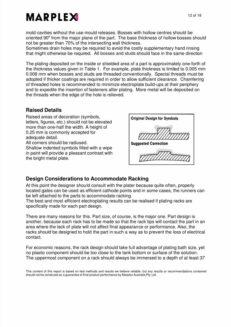
Raised areas of decoration (symbols,letters, figures, etc.) should not be elevatedmore than one-half the width. A height of0.25 mm is commonly accepted foradequate detail.All corners should be radiused.Shallow indented symbols filled with a wipein paint will provide a pleasant contrast withthe bright metal plate.
Design Considerations to Accommodate Racking
At this point the designer should consult with the plater because quite often, properlylocated gates can be used as efficient cathode points and in some cases, the runners canbe left attached to the parts to accommodate racking.The best and most efficient electroplating results can be realised if plating racks arespecifically made for each part design.
There are many reasons for this. Part size, of course, is the major one. Part design isanother, because each rack has to be made so that the rack tips will contact the part in an
area where the lack of plate will not affect final appearance or performance. Also, theracks should be designed to hold the part in such a way as to prevent the loss of electricalcontact.
For economic reasons, the rack design should take full advantage of plating bath size, yetno plastic component should be too close to the tank bottom or surface of the solution.The uppermost component on a rack should always be immersed to a depth of at least 37

8/3/2019 Electroplating ABS
http://slidepdf.com/reader/full/electroplating-abs 13/18
13 of 18
This content of this report is based on test methods and results we believe reliable, but any results or recommendations containedshould not be construed as a guarantee of final product performance by Marplex Australia Pty Ltd.
- 50 mm below the solution surface and the lowest component should be about 150 mmabove the tank bottom.
Other considerations include variations in tank size as well as differences in heights thatthe work rod may be placed above the solution. Otherwise, parts to be plated may fail tobe submerged in one or more of the plating baths. Rack splines and hooks constructed ofcopper, bronze, or brass and vinyl coated for protection against acids used in the cleaningand etching solutions are recommended.
Rack tips of 316 stainless steel are recommended. They can be chemically strippedwithout damaging the points. Rack splines, tips and hooks must be of ample size to allowcurrent to pass without overheating. (Overheating reduces plating efficiency and destroysthe rack coating.) A safe figure for copper is 0.64 amp/m2 of cross section; however, thiscan be extended to 1.29 amp/m2 if the plating cycle is short, the solution cool, and goodcontact is made between the tips and the parts. Brass (60-40 Cu-Zn) has a conductivity28% that of copper. Stainless steel type 316 has a conductivity 2.2% that of copper.Provide for auxiIiary anodes or shields which sometimes may be required.
Finally, the part should be sufficiently rigid to be held on the rack in agitated solutions atelectroplating temperatures (up to 68°C) without warpage. Generous wall thickness willprovide the necessary rigidity, or ribs can be used as an alternative.
Converting Methods And Processing
Moulding and extrusion techniques for converting ASTALAC™ and ASTALOY™ brandpellets to plastic products – suitable for quality electroplating – are dealt with in thissection, including operating conditions, procedures and recommendations. However,before discussing these processing methods, the various grades of ASTALAC especiallydeveloped for metal plating are briefly described. Typical properties are given in table 3.
Injection Moulding Grades
ASTALAC™ EPC is a grade of resin especially suited for decorative plated interiorapplications.ASTALAC™ EPF has been specifically formulated for applications requiring improvedperformance over a wider temperature range with a heavy corrosive resistant plate. EPF
exhibits good adhesion and processing characteristics, and offers excellent thermalcycling properties.ASTALOY™ EHA is an alloy of ABS and Polycarbonate developed for injection moldingwhere higher thermal, impact, creep resistance and toughness are required.

8/3/2019 Electroplating ABS
http://slidepdf.com/reader/full/electroplating-abs 14/18
14 of 18
This content of this report is based on test methods and results we believe reliable, but any results or recommendations containedshould not be construed as a guarantee of final product performance by Marplex Australia Pty Ltd.
Mould Design and Specifications
Any conventional two-plate, three-plate, hot runner, or runnerless type mould can be usedwith ASTALAC™ and ASTALOY™ resins. Kirksite castings or other low cost mouldmaterials may be used for prototype work, but for actual production another choice shouldbe made.
Copper beryllium alloys, unless chrome plated, are not recommended as mould materials. These alloys tend to react with ABS and cause a film on the mould surface which can result in low plate adhesion.
Mould Surface
The quality of appearance for any plated part is dependent upon the quality of the mouldsurface. As with surface irregularities, the bright metal plate will accentuate rather thanhide roughness caused by the mould. Therefore, when optimum appearance isnecessary, the mould finish should be specified in micro meters and the best non-poroustool steel and finishing techniques should be used. A mould finish of 0.38 - 0.45 µm is
recommended. Usual terms for defining the mould finish such as “highly polished”, “mirrorfinish”, or “high lustre”, do not adequately describe what is needed for superlative results.
Texturing
Textured surfaces of various designs can be produced in the mould surface andreproduced in the plated part with fine definition. These often enhance the part’s appealas well as camouflage slight imperfections. Texturing eliminates the mirror image, butdoes not reduce the brightness of a decorative plate. Special plating solutions arerecommended to produce satin or mat finishes.
Mould Shrinkage
The mould shrinkage of 0.6 ± 0.2% should be used for both ASTALAC™ andASTALOY™. These resins freeze quickly to a rigid condition at mould temperatures, somould cavities for parts having threads, undercuts, or texturing should not be designed forstraight stripping.
Gating
Conventional gates and gating methods – such as sprue or centre, edge, disc or
diaphragm, ring, tab, tunnel, fan and multigating can be used. Whenever possible, thegate should be located in a non-appearance area. A typical full-round edge gate in asection 3.2 mm thick is 2.4 mm - 3.2 mm in diameter. For a rectangular edge gate it is 4.8mm - 6.4 mm in width. (Material drag and orientation will be reduced if, on a rectangulargate, the corners are rounded). Land length for these gates should be 0.75 mmmaximum.

8/3/2019 Electroplating ABS
http://slidepdf.com/reader/full/electroplating-abs 15/18
15 of 18
This content of this report is based on test methods and results we believe reliable, but any results or recommendations containedshould not be construed as a guarantee of final product performance by Marplex Australia Pty Ltd.
Single or multiple tab gates will minimise jetting, blush and gate strain, all of which aredetrimental to plating. Tab gates should have dimensions in the range 12.7 mm - 19 mmlong; 10 mm - 16 mm wide; and 2.4 mm - 3.2 mm deep.
Tunnel gates can be used to avoid gating at the parting line of the mould and to provideautomatic degating. A large tunnel tapering 20° or more to a gate of approximately 2.4mm diameter is machined from the runner to the cavity, to a sub-surface tab machinedinto the core, or to a ground flat on a knock-out pin. The length of the subsurface tabshould extend about 6.4 mm beyond the tunnel entrance.
Venting
Moulds must be well vented to eliminate any possibility of gas being trapped as a part ismoulded. The vents are located wherever gas build-up is likely to occur. These shouldbe milled slots approximately 6.4mm wide and no more than 0.05 mm deep. About 3.2mm back from the part the slot depth should be increased for better venting. Alternately,
knock-out pins may be used as vents. Such venting will help keep the part free of surfaceblemishes. Kirksite and other soft mould materials are difficult to vent at the mould partingline, as clamping pressure tends to deform and eventually close off the vent opening.
Nozzles
The use of an unsuitable nozzle in moulding ASTALAC™ or ASTALOY™ can lead todefects such as short shots, jetting, lamination and colour streaking of the material.However, these problems can be minimised by the nozzle having a large orifice and veryshort land length.
Orifice diameters of 5 mm - 10 mm (depending on the machine size and shot) and landlengths not exceeding 3.2 mm are recommended. A small orifice or long land length willcreate surface stress which adversely affects plate adhesion.
Shutoffs or other flow obstructions in the nozzle should be avoided.
Moulding Conditions and Procedures
Data generated in Marplex’s Technical Laboratory and through extensive field testingprovide the recommendations in the following table.

8/3/2019 Electroplating ABS
http://slidepdf.com/reader/full/electroplating-abs 16/18
16 of 18
This content of this report is based on test methods and results we believe reliable, but any results or recommendations containedshould not be construed as a guarantee of final product performance by Marplex Australia Pty Ltd.
Typical Processing Conditions
ASTALAC™ ASTALAC™ ASTALOY™
Conditions EPC EPF EHATemperature of pallet bedof de-humidified drier
85 - 90 °C 85 - 90 °C 95 - 100 °C
Minimum time pallets atdesired Temperature
3 -6 h 3 -6 h 3 - 6 h
Die Temperature 50 - 80 °C 50 - 80 °C 60 - 100 °CNozzle Do Not Exceed Stock Do Not Exceed Stock Do Not Exceed Stock
Stock Temperature 200 - 225 °C 240 - 270 °C 240 - 290 °CZone 1 (Rear) 200 - 230 °C 225 - 245 °C 225 - 265 °CZone 2 (Middle) 210 - 240 °C 235 - 255 °C 235 - 275 °CZone 3 (Front) 210 - 240 °C 245 - 265 °C 245 - 285 °CFill Speed
Slow Slow SlowScrew Speed 40 - 60 RPM 40 - 60 RPM 40 - 60 RPMBack pressure 0.1 - 0.5 MPa 0.1 - 0.5 MPa 0.1 - 0.5 MPaInjection Pressure Minimum Minimum MinimumClamp Tonnage 6 -3 kN / cm2 6 -3 kN / cm2 4 - 8 kN / cm2
Machines
Where a choice is available, a screw injection machine should be used rather than a ramtype. The screw injection machine will deliver stock with a more uniform temperature frombeginning to end of the shot and produce a moulded part with a minimum of surface
stresses.
Mould Lubrication
ASTALAC™ and ASTALOY™ brand resins are self releasing and do not require mouldrelease agents. These agents are nearly impossible to remove in the plating process,usually resulting in bath contamination and rejected parts.
Regrind
Clean, dry, non-degraded regrind will not adversely affect adhesion values. It can bemixed with virgin pellets of the same grade up to a 20% level. However, the proportionshould be kept constant throughout the run, so that the stock temperature and rate of feedwill not vary. Heavy duty grinders with 8 - 10 mm screens are recommended with finematerial removed

8/3/2019 Electroplating ABS
http://slidepdf.com/reader/full/electroplating-abs 17/18
17 of 18
This content of this report is based on test methods and results we believe reliable, but any results or recommendations containedshould not be construed as a guarantee of final product performance by Marplex Australia Pty Ltd.
Purging
Clean up when changing from ASTALAC™ resins to ASTALOY™ brand alloys or viceversa, or from one grade or color of either material to another - or from ABS to a different
material - purging rarely presents any problem. If difficulty occurs in purging, however, themachine may be satisfactorily cleaned by purging with ground acrylic 204°C - 225°C.with the nozzle still attached, allowing two to three minute intervals between shots.
HANDLING OF FORMED PARTS FOR PLATING
Clean and careful handling of moulded parts for electroplating is imperative. Anythingless is apt to result in inferior, and perhaps unacceptable parts.
Attention should be focused on the fact that the slightest blemish on a part surface willstand out after a bright metal finish has been applied. Therefore, caution should be taken
when removing runners or trimming thermoformed parts, not to leave surface defects toolarge for plating success.
Gates and parting lines located in prime appearance areas may necessitate buffing. Lowor non-greasy compounds such as Matchless 4B-28 are recommended. Wheel speeds150 – 180 RPM (250 - 300 mm wheel) and stitched unbleached muslin wheels of mediumweave are common. A clean wheel is used to remove excess compound and reduce thecleaning cycle during the plating process.
ASTALAC™ parts to be plated must be handled in a manner to prevent any surfacemarring or contamination. Cotton gloves should be worn when removing parts from the
mould in order to prevent excessive fingerprinting. Fingerprints may leave an oily filmwhich, when imbedded in the hot plastic surface, will prevent strong plate adhesion if theplating system does not include a cleaning bath as its first step.
Parts can also be soiled by grease or other such contaminants in and around themoulding equipment, particularly in the mould cavities themselves, making the parts moredifficult to plate. Moulds must be free from all preservatives and lubricants.
The production parts should be kept out of any area where mould lubrication might beunder way. Mould releases, especially silicone sprays, can contaminate the air and beattracted to the parts by static charge, not to be noticed until the parts prove difficult to wet
in the plating process.
Once removed from the mould, the ASTALAC™ parts should be adequately protected inshipping containers to prevent scuffing and scratching. Cotton gloves again are normallyused in handling the parts just prior to plating. The finished parts are usually wrappedindividually and shipped in strong packing containers to the end users.

8/3/2019 Electroplating ABS
http://slidepdf.com/reader/full/electroplating-abs 18/18
18 of 18
This content of this report is based on test methods and results we believe reliable, but any results or recommendations containedshould not be construed as a guarantee of final product performance by Marplex Australia Pty Ltd.
Parts to be packaged in polyethylene bags must be cooled to below 37°C beforepackaging.