Embed Size (px)
Citation preview

Instruction Manual
Electronic Total Station
R-315(N)/R-325(N)/R-335(N)/R-322(N)/R-323(N)/R326
Special Functions
PSF Software Ver.365
PENTAX Industrial Instruments CO., Ltd.
Document Ver. 1.10
R-300 SERIES
®

PSF Software Ver.365
1
Copyright
Copyright © 2002 PENTAX Industrial Instruments Co., Ltd. All Rights Reserved PENTAX Industrial Instruments Co., Ltd. is a sole proprietor of the PSF software. The PSF software and publication or parts thereof, may not be reproduced in any form, by any method, for any purpose. PENTAX Industrial Instruments Co., Ltd. makes no warranty, expressed or implied, including but not limited to any implied warranties or merchantability or fitness for a particular purpose, regarding these materials and makes such materials available.
Document Ver.1.10: July 2004
Before using this product, be sure that you have thoroughly read and understood this instruction manual to ensure proper operation. After reading this manual, be sure to keep in a convenient place for easy reference
PSF Software Ver.365
2
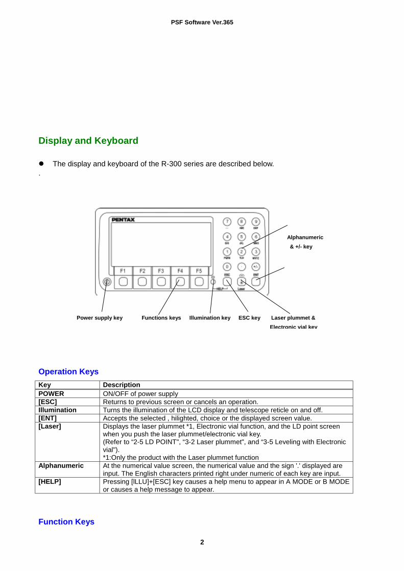
Display and Keyboard The display and keyboard of the R-300 series are described below.
.
Operation Keys Key Description POWER ON/OFF of power supply [ESC] Returns to previous screen or cancels an operation. Illumination Turns the illumination of the LCD display and telescope reticle on and off. [ENT] Accepts the selected , hilighted, choice or the displayed screen value. [Laser] Displays the laser plummet *1, Electronic vial function, and the LD point screen
when you push the laser plummet/electronic vial key. (Refer to “2-5 LD POINT", “3-2 Laser plummet", and “3-5 Leveling with Electronic vial"). *1:Only the product with the Laser plummet function
Alphanumeric At the numerical value screen, the numerical value and the sign '.' displayed are input. The English characters printed right under numeric of each key are input.
[HELP] Pressing [lLLU]+[ESC] key causes a help menu to appear in A MODE or B MODE or causes a help message to appear.
Function Keys
Power supply key Functions keys Illumination key ESC key Laser plummet & Electronic vial key
Alphanumeric & +/- key

PSF Software Ver.365
3
Display F Key Description Mode A [MEAS] F1 Pressing this key one-time measures the distance and measurement type can be
selected by Initial Setting 2. [MEAS] F1 Pressing this key twice measures the distance and another measurement type
can be selected by Initial Setting 2. [TARGET] F2 Select whether the target is SHEET/PRISM/REFRECTORLESS.) [0 SET] F3 Resets the horizontal angle to 0° 0' 0" by pressing twice. [DISP] F4 Toggles the display composition in the order "H.angle/H.dist./V.dist.",
"H.angle/V.angle/S.dist.", and “H.angle/V.angle/H.dist./S.dist./V.dist". [MODE] F5 Toggles the screen between MODE A and MODE B. Mode B [S.FUNC ] F1 PSF Special Functions
[ANG SET]
F2 Brings up the angle setting screen for setting angle-related parameters (ANGLE, %GRADE, H.ANGLE INPUT and R/L REVERSE).
[HOLD ] F3 Pressing this key twice retains (holds) the horizontal angle shown on the display.
[CORR ] F4 Brings up the screen for changing the Target constant, Temperature, Pressure setting
[MODE ] F5 Toggles the screen between MODE A and MODE B. Other functions [←←←←] F1 Moves the cursor to the left. [→→→→] F2 Moves the cursor to the right. [△△△△] F1 Goes back five Items on the screen [▽▽▽▽] F2 Goes forward five items on the screen. RETICLE F3 Changing the Reticle illumination when pressing Illumination key [↑↑↑↑] F3 Moves the cursor up LCD F4 Changing the LCD contrast when pressing Illumination key [↓↓↓↓] F4 Moves the cursor down ILLU F5 Changing the LCD illumination when pressing Illumination key [CLEAR] F5 Clears the figure [SELECT] F5 Opens the selection window
Alphanumeric Input The point name is inputted by the Alphanumeric keys as following.
Key Letter under Key Letter & Figure sequential order to input
[ 0 ] [@][.][_][-][:][/][0] [ 1 ] PQRS [P][Q][R][S][p][q][r][s][1] [ 2 ] TUV [T][U][V][t][u][v][2] [ 3 ] WXYZ [W][X][Y][Z][w][x][y][z][3] [ 4 ] GHI [G][H][I][g][h][i][4] [ 5 ] JKL [J][K][L][j][k][l][5] [ 6 ] MNO [M][N][O][m][n][o][6] [ 7 ] [ ][?][!][_][ ][^][|][&][7] [ 8 ] ABC [A][B][C][a][b][c][8] [ 9 ] DEF [D][E][F][d][e][f][9] [ . ] [.][,][:][;][#][(][)] [+/-] [+][-][*][/][%][=][<][>]
Memories in the Instrument
This instrument incorporates not only 8 measuring programs but also a MEMORY MANAGER program as special functions and so it can receive and record Coordinates data and surveying

PSF Software Ver.365
4
data of maximum 7500 points.
Relations between memories and each Special function Special Function
Memory Data to be read Data to be stored
DATA STORAGE
Yes
Job name
Job name, Station P.*1Measured P.*1
COORDINATES
Yes
Job name, Station P.*2 Backsight P.
Job name, Station P.*2 Backsight P., Measured P.*2
COORD. STAKEOUT Yes
Job name, Station P.*2 Backsight P., Stakeout P.
Job name, Station P.*2 Backsight P., Stakeout P.
OFFSET SHOTS
Yes
Job name, Station P.*2 Backsight P.
Job name, Station P.*2 Backsight P., Target P.
RESECTION
Yes Job name, Known P. A,B,C
Job name, Station P.*2 Known P. A,B,C
RDM
----- ----- -----
REM
----- ----- -----
DISTANCE STAKEOUT -----
----- -----
MEMORY MANAGER
Yes (Yes) (Yes)
Each data contents Station P.*1
Station P. No. Description Instrument H. Target C. Temperature Pressure ppm Correction value
Station P.*2 P. No. Coordinate Description Backsight P. P. No. Coordinate Description Stakeout P. P. No. Coordinate Description Target P. P. No. Coordinate Description Known P. P. No. Coordinate Description Measured P.*1 P. No. Prism H. H. Angle V. Angle S. Distance Description Measured P.*2 P. No. Coordinate Description
PSF Software Ver.365
5
CONTENTS Copyright
Display and Keyboard
Memories in the Instrument
Relations between memories and each function
1 INTRODUCTION 1-1 INTRODUCTION 1-2 BEFORE USING THE PSF MANUAL 2 ACCESSING THE SPECIAL FUNCTIONS 2-1 ACCESSING BY SPECIAL KEY 2-2 ACCESSING BY HELP KEY 2-3 ACCESSING BY 007 3 COORD. STAKEOUT General pictures of measurement Detailed Operating procedures 1. JOB NAME 2. STATION SETUP 3. STAKEOUT
4 DISTANCE STAKEOUT General pictures of measurement Detailed Operating procedures 5 RDM General pictures of measurement Detailed Operating procedures 6 COORDINATES General pictures of measurement Detailed Operating procedures 1. JOB NAME 2. STATION SETUP 3. SURVEY 7 OFFSET SHOTS General pictures of measurement Detailed Operating procedures 1. JOB NAME 2. STATION SETUP 3. SURVEY 8 REM General pictures of measurement Detailed Operating procedures
7 7 7 8 8 9 10
11 11 12 12 14 19
23 23 24
25 25 26
27 27 27 27 28 30
31 31 32 32 32 34
35 35

PSF Software Ver.365
6
9 RESECTION General pictures of measurement Detailed Operating procedures 1. JOB NAME 2. STATION SETUP 3. SURVEY
10 DATA STORAGE General pictures of measurement General picture 1. JOB NAME 2. STATION SETUP 3. SURVEY 11 MEMORY MANAGER Detailed Operating procedures 1. COORDINATES SEND 2. COORDINATES RECEIVE 3. COORDINATES EDIT 4. COORDINATES DELETE 5. SURVEY DATA SEND 6. SURVEY DATA EDIT 7. SURVEY DATA DELETE 12 DataLink DL- 01 Software
40 40 40 40 41 41
42 42 42 43 44 44 45 46 47

PSF Software Ver.365
7
1 INTRODUCTION 1.1 INTRODUCTION Thank you for your first looks at PSF by reading this manual. The PSF is a user friendly data collection and calculation program for the PENTAX total station R-300 series. The PSF is developed based on the PCS-300 Special functions, which is known as versatile on-board software for PENTAX PCS-300 total station series. The optimum combination of PCS-300 and R-300 hardware makes PSF as an easy and useful fieldwork tool. The main menu offers you the following possibilities. COORD. STAKEOUT DISTANCE STAKEOUT RDM COORDINATES OFFSET SHOTS REM RESECTION DATA STORAGE MEMORY MANAGER
1.2 BEFORE USING THE R-300 PSF software MANUAL The PSF manual mainly describes the R-300 special functions, and the basic operations are
described in the (basic) R-300 manual. And, therefore, refer to the R-300 basic manual regarding the R-300 general instrument operations.
Before performing PSF functions, select the Target type, “Reflector Sheet” or “Prism” or “Reflectorless”.
General pictures of measurement: This illustrates the content of the program. Detailed Operating procedures:
This describes the actual detailed operating procedures. Since detailing the Operating procedures of each program would cause unnecessary complexity, this manual shows detail for "Coordinate Stakeout Measurement" only, as an example. Descriptions of the other programs are simplified. The guide messages, however, of each step of the operation help you to proceed in a proper manner for the other programs. We are confident, therefore, that you will be able to use the other application programs once you're familiar with the operation of "Coordinate Stakeout Measurement" program.
Press the keys, which are drawn by the index finger.
For further information, please contact your local Pentax Authorized dealer.

PSF Software Ver.365
8
2 ACCESSING THE SPECIAL FUNCTIONS
2-1 ACCESSING BY SPECIAL KEY Example: COORD. STAKEOUT 1
Press the [S.FUNC] key at mode B. (Mode A must be changed to mode B by pressing the [MODE] key.)
Pentax Special Function
2 Move the cursor to 3.COORD.STAKEOUT by pressing [ ∆ ], [ ∇ ] or [ ↑ ], [ ↓ ]key.
Pentax Special Function
3
The COORD.STAKEOUT can be accessed by pressing the [ENT] key.
COORD.STAKEOUT
1.DATA STORAGE 2.COORDINARES 3.COORD.STAKEOUT 4.OFFSET SHOTS 5.RESECTION
1.DATA STORAGE 2.COORDINARES 3.COORD.STAKEOUT 4.OFFSET SHOTS 5.RESECTION
1. JOB NAME 2. STATION SET UP 3. STAKEOUT
Other Pentax Special Function are: Pentax Special Function
5. RESECTION 6. RDM 7. REM 8. DIST STAKEOUT 9. MEMORYMANAGER

PSF Software Ver.365
9
2 ACCESSING THE SPECIAL FUNCTIONS 2-2 ACCESSING BY HELP KEY
Example: COORD. STAKEOUT
1 Press the [ESC] key while pressing the [lLLU] at mode A or B. The HELP menu is displayed.
HELP
2 Move the cursor to 28. COORD.STAKEOUT by pressing [ ∆ ], [ ∇ ] or [ ↑ ], [↓ ] key.
HELP
3
The COORD. STAKEOUT can be accessed by pressing the [SELECT] at F5 key.
COORD.STAKEOUT
1.HELP 2.401 TARGET CONST 3.402 ATM CORR : AUTO 4. 501 MEAS.MIN DISP: COARSE. 5. 502 SHOT COUNT
SELECT
28. 109 COORD. STAKEOUT 29. 112 REM 30. 113 RESECTION 31. 119 DATA STORAGE 32. 200 MEMORY MANAGER SELECT
1. JOB NAME 2. STATION SET UP 3. STAKEOUT

PSF Software Ver.365
10
H.angle 92° 35' 20" H.dst V.dst 109
H.angle 92° 35' 20" H.dst V.dst 000
2 ACCESSING THE SPECIAL FUNCTIONS 2-3 ACCESSING BY 007
Example: COORD. STAKEOUT
1 Press numeric keys of 0-0-7 to enter Command input screen on MODE A or B.
007 CLEAR
2
Press the numeric key 1- 0- 9 of COORD. STAKEOUT.
007
3
Special function COORD.STAKEOUT can be accessed by pressing the [ENT] key.
COORD.STAKEOUT
The PSF Command No. list
Special Functions 007 Command Distance Stakeout 101
RDM 103
Coordinates 104
Offset Shots 105
Coord. Stakeout 109
REM 112
Resection 113
Data Storage 119
MEMORY MANAGER 200
1. JOB NAME 2. STATION SET UP 3. STAKEOUT

PSF Software Ver.365
11
3 COORD. STAKEOUT
General pictures of measurement With COORD. STAKEOUT measurement, "Stakeout point coordinates" can be staked out in 3 dimensions based on the known "Station point coordinates" and the "Backsight point coordinates or Backsight point azimuth". The horizontal angle, horizontal distance and vertical distance to the stakeout point are automatically calculated as design values, and the differences between the measured values and design values are displayed as deviations. When the coordinate values of the Station point, Backsight point and Stakeout point are recorded on the instrument memory, designation of each measured point number makes it possible to omit the each time coordinates value input. General pictures Z N Prism height Backsight point Staking point Instrument height Station point E Design values and deviation N Z Distance deviation Prism Z deviation Horizontal distance design value Staking point Prism Horizontal angle design value Staking point Station point Horizontal angle deviation Backsight point Z design value Backsight point azimuth Station point E E

PSF Software Ver.365
12
3 COORD. STAKEOUT
Detailed Operating procedures
Access the COORD. STAKEOUT according to the "1. ACCESSING THE SPECIAL FUNCTIONS".
1. JOB NAME (1) JOB NAME input
1
Press the [ENT] key to view COORD. STAKEOUT screen.
COORD.STAKEOUT
2 For example, "XXXX" is inputted. Press the [ENT] key to view JOB NAME INPUT screen. Press the [ENT] key to view JOB NAME screen.
Input the JOB NAME “XXXX” by pressing the Alphanumeric keys and arrow key.
JOB NAME INPUT JOB NAME
3 Press the [ENT] key to enter.
STATION NUMBER LIST
Maximum 15 letters can be inputted on the JOB NAME input. When the same JOB NAME is already stored, the stored one is displayed after
pressing the [ENT] key at the Operating procedure 3. "The same job name is found" is displayed.
1. JOB NAME 2. STATION SET UP 3. STAKEOUT
1.
BS CLEAR TO 123
XXXX
1. 000 :

PSF Software Ver.365
13
3 COORD. STAKEOUT
(2) JOB NAME selection
1
Press the [ENT] key.
COORD. STAKEOUT
2 For example, stored "3.BBBB" is selected.
Move the cursor to "3. BBBB" by pressing the [ ∆ ], [ ∇ ], [ ↑ ], [↓ ] keys and press the [ENT] key.
Press the [ENT] key to enter.
JOB NAME INPUT
JOB NAME INPUT
COORD. STAKEOUT
The JOB NAME selection is possible only when some NAME are already stored.
1. JOB NAME 2. STATION SET UP 3. STAKEOUT
1. : 2. XXXX 3. BBBB 4. CCCC 5. DDDD
1. : 2.AAAA 3.BBBB 4. CCCC 5. DDDD
1. JOB NAME 2. STATION SET UP 3. STAKEOUT
PSF Software Ver.365
14
3 COORD. STAKEOUT
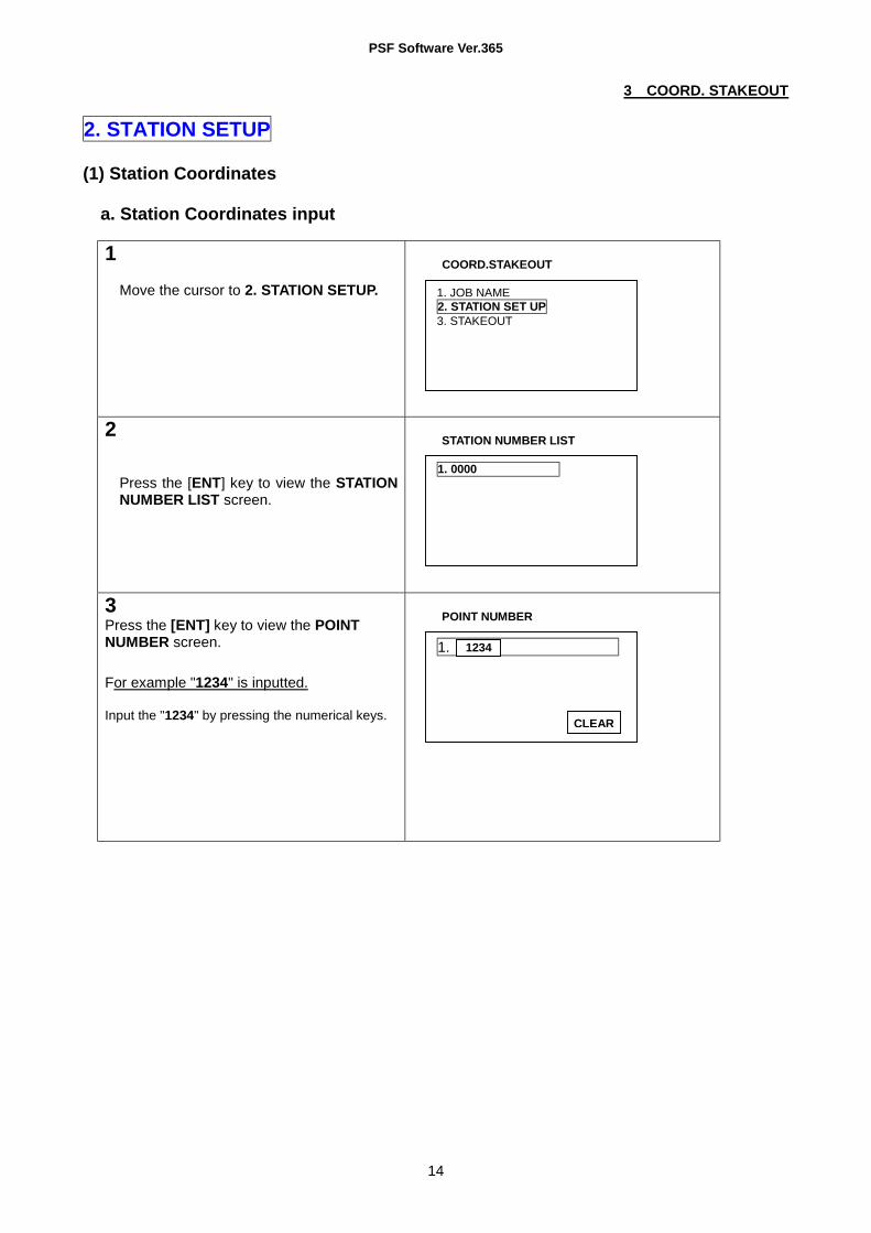
2. STATION SETUP (1) Station Coordinates a. Station Coordinates input
1
Move the cursor to 2. STATION SETUP.
COORD.STAKEOUT
2 Press the [ENT] key to view the STATION NUMBER LIST screen.
STATION NUMBER LIST
3 Press the [ENT] key to view the POINT NUMBER screen. For example "1234" is inputted.
Input the "1234" by pressing the numerical keys.
POINT NUMBER
1. JOB NAME 2. STATION SET UP 3. STAKEOUT
1. 0000
1.
1234
CLEAR

PSF Software Ver.365
15
3 COORD. STAKEOUT 4
Press the [ENT] key to view the STATION COORDINATES INPUT screen.
STATION COORDINATES INPUT
5
For example, X COORDINATE "-123456.890" is inputted as following.
Move the cursor to 3. X and press the [SELECT] key at F5 to input the X COORDINATE.
STATION COORDINATES INPUT
6
Press the numerical key , +/- and point key and input the above figures. Press the [ENT] key to go to Y COORD.
X COORD.
7 Input the Y and Z COORDINATE and INST. H and press the [ENT] key.
STATION COORDINATES INPUT
8
The STATION COORDINATE which is input: For store -Press the [STORE] key. Not for store-Press the [ENT] key.
STATION COORDINATES INPUT
2.DESCRIPTION : 3.X COORD. : 000000.000m 4.Y COORD. : 000000.000m 5.Z COORD. : 000000.000m 6.INST. H : 00.000m STORE SELECT
2.DESCRIPTION : 3.X COORD. : 000000.000m 4.Y COORD. : 000000.000m 5.Z COORD. : 000000.000m 6.INST. H : 00.000m STORE SELECT
2.DESCRIPTION : 3.X COORD. : 000000.000m 4.Y COORD. : 000000.000m 5.Z COORD. : 000000.000m 6.INST. H : 00.000m CLEAR
-123456.890 m
2.DESCRIPTION : 3.X COORD. : - 123456.890 m 4.Y COORD. : 12345.789 m 5.Z COORD. : 123.678 m 6.INST. H : 00.000 m STORE SELECT
2.DESCRIPTION : 3.X COORD. : - 123456.890 m 4.Y COORD. : 12345.789 m 5.Z COORD. : 123.678 m 6.INST. H : 1.3000 m STORE SELECT

PSF Software Ver.365
16
The BACKSIGHT SELECTION screen is viewed.
BACKSIGHT SELECTION
Articles marked by * are not changed. DESCRIPTION input: Press the [SELECT] key, and input letters or marks. Maximum 8 letters can be inputted at the "DESCRIPTION".
b. Search and call of the stored Station Coordinates
1 Move the cursor to 2 STATION SETUP.
COORD.STAKEOUT
2
Press the [ENT] key to view the STATION NUMBER LIST screen.
STATION NUMBER LIST
3 Stored "1234" is searched for example.
Move the cursor to "2. 1234" by pressing the [ ∆ ], [ ∇ ], [ ↑ ], [↓ ] keys and press the [ENT] key to view the INSTRUMENT HEIGHT INPUT screen. Pre-stored data in the Coordinate memory is displayed.
STATION NUMBER LIST INSTRUMENT HEIGHT INPUT
1. COORDINATES INPUT 2.FORESIGHT COORD.(AZIMUTH) INPUT
1. JOB NAME 2. STATION SET UP 3. STAKEOUT
1. 0000 2. 1234 3. 0564 4. 0678
2.DESCRIPTION : * 3.X COORD. : * 113456.890 m 4.Y COORD. : * 22345.789 m 5.Z COORD. : * 323.678 m 6.INST. H : 1.5000 m SELECT
1. 0000 2. 1234 3. 0564 4. 0678

PSF Software Ver.365
17
4
Confirm the called STATION P. COORDINATES and then press the [ENT] key. When the INSTR. H. change is needed, change the height value, and press the [ENT] key to view the BACKSIGHT SELECTION screen.
BACKSIGHT SELECTION
(2) Backsight Selection a. Coordinates input The Backsight Point Number and Coordinates input
1 BACKSIGHT SELECTION
2
Push the [ENT] key at "1.COORDINATES INPUT". BACKSIGHT NUMBER LIST screen is viewed.
BACKSIGHT NUMBER LIST
3 Press the [ENT] key to view the POINT NUMBER screen. Input the Backsight point number according to the STATION P.NUMBER input. Press the [ENT] key to view the BACKSIGHT COORDONATES INPUT screen.
POINT NUMBER
1. COORDINATES INPUT 2.FORESIGHT COORD.(AZIMUTH) INPUT
1. 0000
CLEAR
1. 0025
1. COORDINATES INPUT 2.FORESIGHT COORD.(AZIMUTH) INPUT
PSF Software Ver.365
18
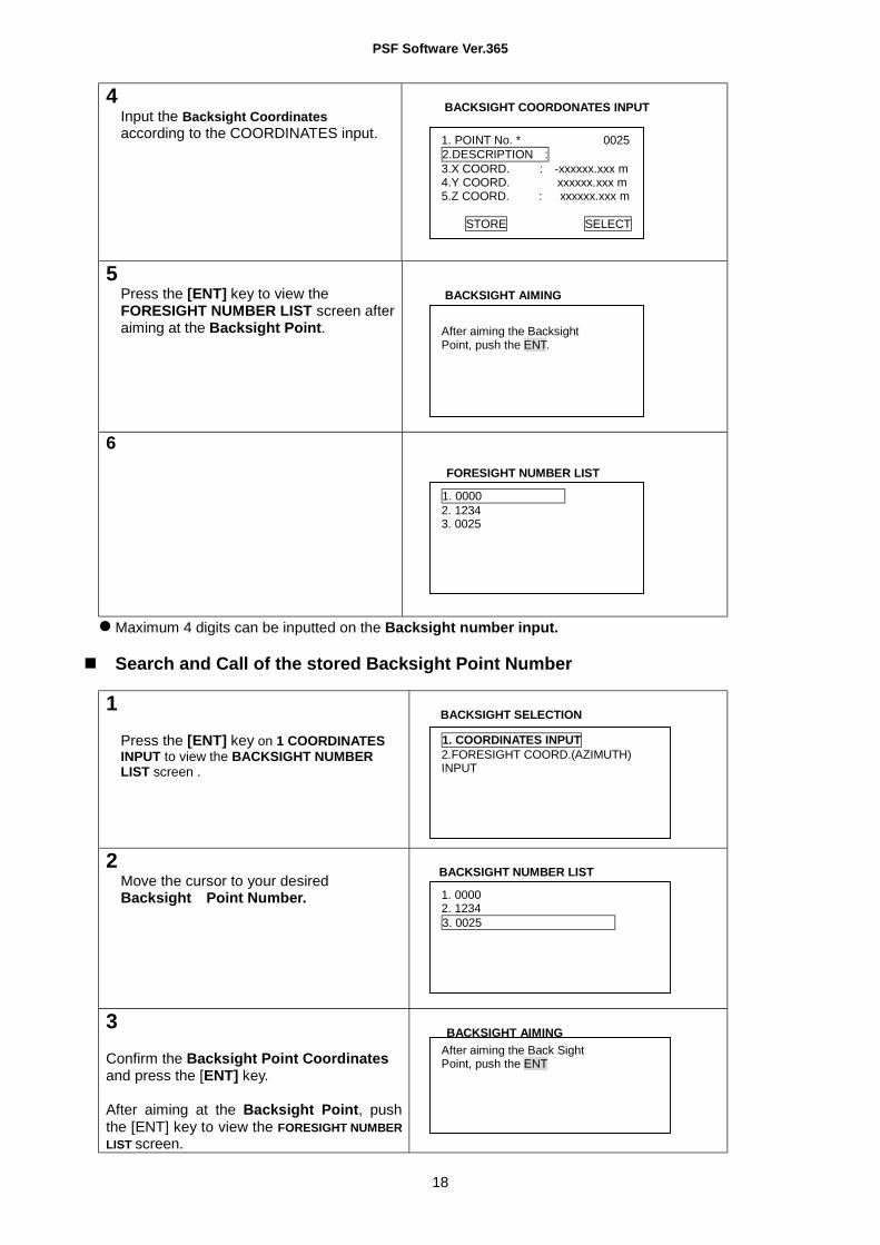
4 Input the Backsight Coordinates according to the COORDINATES input.
BACKSIGHT COORDONATES INPUT
5 Press the [ENT] key to view the FORESIGHT NUMBER LIST screen after aiming at the Backsight Point.
BACKSIGHT AIMING
6
FORESIGHT NUMBER LIST
Maximum 4 digits can be inputted on the Backsight number input.
Search and Call of the stored Backsight Point Number
1
Press the [ENT] key on 1 COORDINATES INPUT to view the BACKSIGHT NUMBER LIST screen .
BACKSIGHT SELECTION
2 Move the cursor to your desired Backsight Point Number.
BACKSIGHT NUMBER LIST
3 Confirm the Backsight Point Coordinates and press the [ENT] key.
After aiming at the Backsight Point, push the [ENT] key to view the FORESIGHT NUMBER LIST screen.
BACKSIGHT AIMING
1. COORDINATES INPUT 2.FORESIGHT COORD.(AZIMUTH) INPUT
After aiming the Back Sight Point, push the ENT
1. 0000 2. 1234 3. 0025
1. 0000 2. 1234 3. 0025
1. POINT No. * 0025 2.DESCRIPTION : 3.X COORD. : -xxxxxx.xxx m 4.Y COORD. xxxxxx.xxx m 5.Z COORD. : xxxxxx.xxx m STORE SELECT
After aiming the Backsight Point, push the ENT.

PSF Software Ver.365
19
4
FORESIGHT NUMBER LIST
b. Azimuth angle input
1 Move the cursor to 2. FORESIGHT COORD. (AZIMUTH) INPUT and press the [ENT] key, and go to the Operating procedures 2 of 3. STAKEOUT.
BACKSIGHT SELECTION
FORESIGHT NUMBER LIST
The Azimuth angle input is performed at the Operating procedures 1) - 3) of BACKSIGHT SELECTION screen in 3. STAKEOUT.
3. STAKEOUT (1) Input and Stakeout of Foresight Point Number and Coordinates
1
Move the cursor to 3. STAKEOUT.
COORD. STAKEOUT
2
Press the [ENT] key.
FORESIGHT NUMBER LIST
1. 0000 2. 1234 3. 0025
1. 0000 2. 1234 3. 0025
1. JOB NAME 2. STATION SET UP 3. STAKEOUT
1. 0000 2. 1234 3. 0025
1. COORDINATES INPUT 2.FORESIGHT COORD.(AZIMUTH) INPUT
PSF Software Ver.365
20
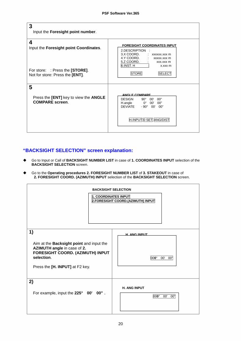
3 Input the Foresight point number.
4 Input the Foresight point Coordinates. For store: : Press the [STORE]. Not for store: Press the [ENT].
FORESIGHT COORDINATES INPUT
5 Press the [ENT] key to view the ANGLE COMPARE screen.
ANGLE COMPARE
“BACKSIGHT SELECTION” screen explanation: Go to Input or Call of BACKSIGHT NUMBER LIST in case of 1. COORDINATES INPUT selection of the
BACKSIGHT SELECTION screen. Go to the Operating procedures 2. FORESIGHT NUMBER LIST of 3. STAKEOUT in case of
2. FORESIGHT COORD. (AZIMUTH) INPUT selection of the BACKSIGHT SELECTION screen.
BACKSIGHT SELECTION 1)
Aim at the Backsight point and input the AZIMUTH angle in case of 2. FORESIGHT COORD. (AZIMUTH) INPUT selection.
Press the [H. INPUT] at F2 key.
H. ANG INPUT
2)
For example, input the 225° 00' 00" .
H. ANG INPUT
DESIGN 90° 00' 00" H.angle 0° 00' 00" DEVIATE - 90° 00' 00" H.INPUT 0 SET ANG/DIST
000° 00' 00"
000° 00' 00"
2.DESCRIPTION : 3.X COORD. : xxxxxx.xxx m 4.Y COORD. : xxxxx.xxx m 5.Z COORD. : xxx.xxx m 6.INST. H : x.xxx m STORE SELECT
1. COORDINATES INPUT 2.FORESIGHT COORD.(AZIMUTH) INPUT

PSF Software Ver.365
21
3)
Press the [ENT] key.
ANGLE COMPARE
6 Rotate the instrument horizontally and stop it where the displayed DEVIATE becomes 0 and fix the horizontal rotation.
ANGLE COMPARE
7
Press the [ANG/DIST] at F4 key.
DIST. COMPARE
8
Move the prism toward the aiming direction of a telescope, and press the [TRACK] at F2 key and aim at the prism.
DIST. COMPARE
9
The DEVIATE value approaches to 0, and then press the [MEAS] at F1 key. Find a place where the DEVIATE value becomes exactly 0, and the place is the STAKEOUT POINT. The STAKEOUT of the first STAKEOUT POINT is completed.
DIST. COMPARE
10
Press the [ENT] key. The Stakeout of the second or third Stakeout point is performed in the same way.
FORESIGHT NUMBER LIST
DESIGN 90° 00' 00" H.angle 90° 00' 00" DEV.IATE 00° 00' 00" H.INPUT 0 SET ANG/DIST
H.dst DESIGN 360.555 m Z coord.DESIGN 0.000 m H.dst DEVIAT Z coord.DEVIAT S.dst MEAS TRACK TARGET ANG/DST
H.dst DESIGN 360.555 m Z coord. DESIGN 0.000 m H.dst DEVIAT -2.835 m Z coord. DEVIAT -0.242 m S.dst 378.452 m MEAS TRACK TARGET ANG/DIST
H.dst DESIGN 360.555 m Z coord. DESIGN 0.000 m H.dst DEVIAT 0.000 m Z coord. DEVIAT 0.000 m S.dst 378.452 m MEAS TRACK TARGET ANG/DST
1. 0000
DESIGN 90° 00' 00" H.angle 0° 00' 00" DEVIATE - 90° 00' 00" H.INPUT 0 SET ANG/DIST

PSF Software Ver.365
22
At the procedure 6, the 00" of the DEVIATE.value can be easily got if the minimum count is set to 1 ". At the procedure 8, a prism can be easily tracked if a position is searched using the [TRACK] function
and then using the [MEAS] function.
(2) Search and Call of the stored Foresight Point Number
1
Move the cursor to 3. STAKEOUT
COORD.STAKEOUT
2
Press the [ENT] key.
FORESIGHT NUMBER LIST
3 Search for the desired Foresight point number.
4
Confirm the called Foresight Coordinates and press [ENT] key. If the prism height change is necessary, press the [ENT] key after the change.
ANGLE COMPARE
1. JOB NAME 2. STATION SET UP 3. STAKEOUT
1. 0000 2. 1234 3. 0025
DESIGN 90° 00' 00" H.angle 0° 00' 00" DEVIATE. - 90° 00' 00" H.INPUT 0 SET ANG/DIST
PSF Software Ver.365
23
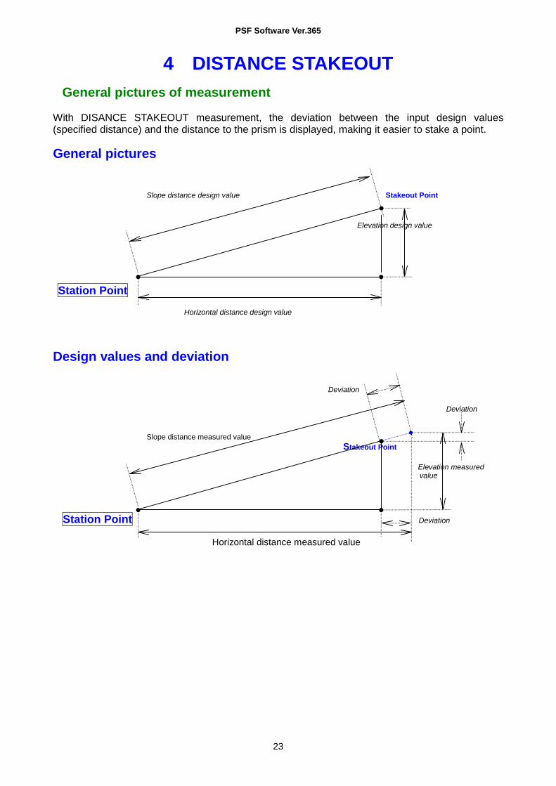
4 DISTANCE STAKEOUT
General pictures of measurement
With DISANCE STAKEOUT measurement, the deviation between the input design values (specified distance) and the distance to the prism is displayed, making it easier to stake a point. General pictures Slope distance design value Stakeout Point Elevation design value Station Point Horizontal distance design value Design values and deviation Deviation Deviation Slope distance measured value Stakeout Point Elevation measured value Station Point Deviation Horizontal distance measured value

PSF Software Ver.365
24
4 DISTANCE STAKEOUT
Detailed Operating procedures Access the DISTANCE STAKEOUT according to "1. ACCESSING THE SPECIAL FUNCTIONS". Step 1 Selecting the distance to be displayed and inputting the design values. (1) 1 .H.dist. SELECT Input H.dist.
ENT ENT DIST COMPARE To Step 2
* Input the S.dist. and V.dist. in the same way. Step 2 STAKEOUT start (1) TRACK / MEAS
(2) (3)
A prism can be easily tracked if a position is searched by using a [TRACK]
function and then using a [MEAS] function.
DISTANCE STAKEOUT
Move the prism to the ground point where the deviation is "0"
Use the ground point where the deviation is "0" as the STAKEOUT point
Use the [ENT] key to exitthe STAKEOUT function
Go back to Step 1
If necessary, repeat the measurement
Use the [ESC] key to exit the distance stake-out function

PSF Software Ver.365
25
5 RDM
General pictures of measurement With RDM measurement, the horizontal distance, the slope distance, difference in height and the percentage of slope between the reference point and the observation point are measured. The distance between one observation point and another observation point is measured as well. General Pictures Slope distance Target Slope % Height difference Reference Point Horizontal distance Station Point REF.P-P P-P P-P P-P Target Target Reference Point Target REF.P.-P REF.P.-P REF.P.-P Target REF.P.-P

PSF Software Ver.365
26
5 RDM Detailed Operating procedures
Access the RDM according to "1. ACCESSING THE SPECIAL FUNCTIONS". Step 1 Observation of the reference point (1) PRISM H INPUT PRIZM H ENT MEAS
ENT Go to Step 2 Step 2 Observation of the target point (P1) (1) PRISM H INPUT PRISM H ENT MEAS
ENT ENT
(2) PRISM H INPUT PRISM H ENT MEAS
ENT ENT
*Use [DIST] key to change the distance display (REF-P/P-P) (3) PRISM H INPUT PRISM H ENT MEAS
ENT
* Use [DIST] key to change the distance display (REF-P/P-P)
The slope that can be calculated and displayed with the RDM function is within +/-200.00 %. The difference in height is indicated in +/-.
Display the distance to P1
Display the distance between the reference point and P1
Display the distance to
Display the distance between the reference point and P2, and the distance between P1 and P2
Display the distance to Px
Display the distance between the reference point and Px, and the distance between P (x-1) and Px
Display the distance to the Reference Point

PSF Software Ver.365
27
6 COORDINATES
General pictures of measurement Any desired Target coordinates can be determined and stored by setting a Station Point as an original point and inputting the Backsight coordinate in COORDINATES measurement. The coordinates values from Original coordinates point can be determined by the Station coordinates input even if the Station Point is not set as original point. Coordinates values input can be omitted by designating the Station Point No. whenever the Station coordinates are stored in the internal memory. General pictures Z N Target Backsight Point Target Station Point E
Detailed Operating procedures Access the COORDINATES according to " ACCESSING THE SPECIAL FUNCTIONS ".
1. JOB NAME (1) JOB NAME input ( Selection keys: ⇓⇑⇒⇐ ,,, )
1.JOB NAME ENT COORDINATE JOB NAME INPUT ENT
JOB NAME input by pressing selection keys ENT
(2) JOB NAME selection ( Selection keys: ⇓⇑∇∆ ,,, ) 1. JOB NAME ENT COORDINATES JOB NAME INPUT
Select the JOB NAME by shift keys ENT To the primary screen of the COORDINATES The JOB NAME can be selected only when the JOB NAMES are already stored.

PSF Software Ver.365
28
6 COORDINATES
2. STATION SETUP (1 ) STATION COORDINATES
a. STATION COORDINATES input
2. STATION SETUP ENT STATION P.NUMBER LIST STATION P.NUMBER INPUT
ENT STATION COORDINATES INPUT 2. DESCRIPTION SELECT DESCRIPTION INPUT
ENT X COORDINATE SELECT
Input X COORDINATE ENT Y COORDINATE SELECT
Input Y COORDINATE ENT Z COORDINATE SELECT
Input Z COORDINATE ENT INSTR. H. SELECT
Input INSTR. H. ENT STORE
BACKSIGHT SELECTION ENT Maximum 4 digits can be inputted at STATION P.NUMBER. Please press the [STORE] key to store the input data. Maximum 8 letters can be inputted at the "DESCRIPTION”.
b. Search and call of stored STATION COORDINATES
2. STATION SETUP ENT STATION P.NUMBER LIST STATION P.NUMBER by shift keys ENT Confirm the STATION COORDINATES values INSTR.H. SELECT
Input the INSTR. H. ENT BACKSIGHT SELECTION The INSTR.H. can be changed.
(2) BACKSIGHT SELECTION
a. COORDINATES INPUT BACKSIGHT P. NUMBER and COORDINATES input
BACKSIGHT SELECTION 1 . COORDINATES INPUT ENT BACKSIGHT P. NUMBER LIST ENT Input the P.No ENT BACKSIGHT COORDINATES INPUT 2. DESCRIPTION SELECT DESCRIPTION INPUT ENT
X COORDINATE SELECT Input X COORDINATE ENT
Y COORDINATE SELECT Input Y COORDINATE ENT
Z COORDINATE SELECT Input Y COORDINATE ENT

PSF Software Ver.365
29
6 COORDINATES STORE
Aim at the Backsight Point ENT SURVEY ENT Maximum 4 digits can be inputted at the BACKSIGHT P. NUMBER. Please press the STORE key to store the input data.
Search and call of the stored BACKSIGHT P. NUMBER
BACKSIGHT SELECTION 1. COORDINATES INPUT ENT
BACKSIGHT P. NUMBER Select by shift keys ENT
Confirm the BACKSIGHT P. COORDINATES values ENT
Aim at the Backsight point ENT SURVEY Shift keys: ( ⇓⇑∇∆ ,,, )
b. AZIMUTH input
BACKSIGHT SELECTION 2. AZIMUTH INPUT ENT
Aim at the Backsight point Press F5 (1/2) Press H. INPUT
AZIMUTH INPUT ENT Press F5 (2/2)
"Aim at the Backsight point" is not displayed.

PSF Software Ver.365
30
6 COORDINATES
3. SURVEY
(1) 3. SURVEY ENT Press the [POINT] key
1. POINT No. SELECT POINT No. input ENT
2. DESCRIPTION SELECT DESCRIPTION INPUT ENT
3. PRISM H. SELECT PRISM H. input ENT ENT
Measure the P1 XYZ COORDINATES are displayed STORE / ENT
Maximum 4 digits can be inputted at the POINT NUMBER. Please press the [STORE] key to store the measured data. The PRISM H. can be changed.
(2) POINT P2 P3, P4, -Px are measured in the same way. (3) SURVEY is completed by ESC key. If necessary, repeat the measurement.
The COORDINATES is completed by pressing the ESC key.
MEASURED POINT 1.POINT No. 2.DESCRIPTION 3.PRISM H
PSF Software Ver.365
31
7 OFFSET SHOTS
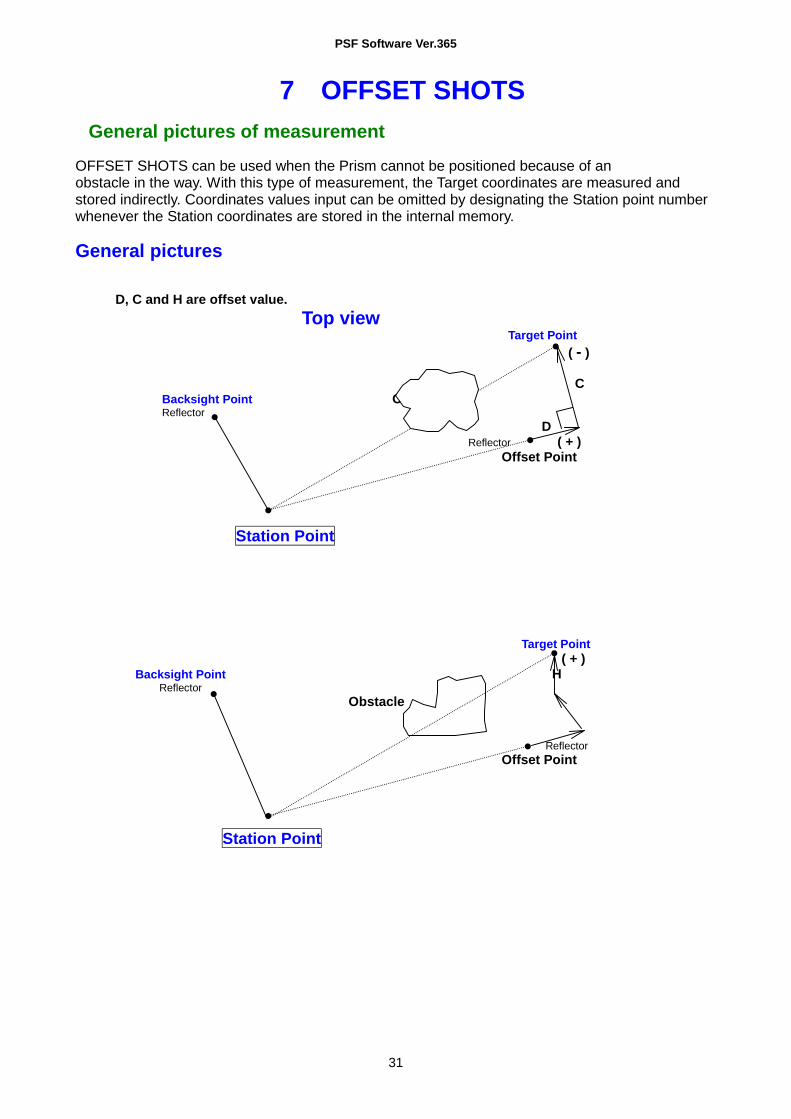
General pictures of measurement OFFSET SHOTS can be used when the Prism cannot be positioned because of an obstacle in the way. With this type of measurement, the Target coordinates are measured and stored indirectly. Coordinates values input can be omitted by designating the Station point number whenever the Station coordinates are stored in the internal memory. General pictures D, C and H are offset value. Top view Target Point ( - ) C Backsight Point Obstacle Reflector D Reflector ( + ) Offset Point Station Point Target Point ( + ) Backsight Point H Reflector Obstacle Reflector Offset Point Station Point

PSF Software Ver.365
32
7 OFFSET SHOTS
Detailed Operating procedures
1. JOB NAME
(1) JOB NAME input ( Selection keys: ⇓⇑⇒⇐ ,,, ) 1. JOB NAME ENT COORDINATE JOB NAME INPUT Screen ENT
JOB NAME input by pressing selection keys ENT STATION P. NUMBER LIST Screen
ENT P No ENT
(2) JOB NAME selection ( Selection keys: ⇓⇑⇒⇐ ,,, ) 1 . JOB NAME ENT COORDINATE JOB NAME INPUT Screen
Select the JOB NAME by shift keys ENT To the primary screen of OFFSET SHOTS The JOB NAME can be selected only when it is already stored.
2. STATION SETUP
(1) STATION COORDINATES a. STATION COORDINATES input 2. STATION SETUP ENT STATION P. NUMBER LIST Screen ENT P. No input
ENT STATION COORDINATES INPUT Screen 2. DESCRIPTION SELECT
DESCRIPTION INPUT ENT X COORDINATE SELECT
Input Y COORDINATE ENT Y COORDINATE SELECT
Input Z COORDINATE ENT Z COORDINATE SELECT
Input INSTR. H. ENT STORE
BACKSIGHT SELECTION Screen ENT Maximum 4 digits can be inputted at STATION P. NUMBER. Please press the [STORE] key to store the input data. Maximum 8 letters can be inputted at the "DESCRIPTION".
b. Search and call of the stored STATION COORDINATES 2. STATION SETUP ENT STATION P. NUMBER LIST Screen
SELECT the NUMBER by shift keys ENT Confirm the STATION COORDINATES values
INSTR. H. SELECT INPUT INSTR. H. ENT
BACKSIGHT SELECTION Screen

PSF Software Ver.365
33
7 OFFSET SHOTS The INSTR. H, can be changed.
(2) BACKSIGHT COORDINATES
a. COORDINATES input BACKSIGHT COORDINATES input
BACKSIGHT SELECTION Screen 1.COORDINATES INPUT ENT
BACKSIGHT P. NUMBER LIST Screen ENT P No input ENT
BACKSIGHT COORDINATES INPUT Screen 2. DESCRIPTION
SELECT DESCRIPTION INPUT ENT
X COORDINATE SELECT Input X COORDINATE ENT
Y COORDINATE SELECT Input Y COORDINATE ENT
Z COORDINATE SELECT Input Z COORDINATE ENT STORE
Aim at the Backsight point ENT SURVEY ENT
Maximum 4 digits can be inputted at the BACKSIGHT P. NUMBER. Please press the [STORE] key to store the input data.
Search and call of the stored BACKSIGHT COORDINATES BACKSIGHT SELECTION Screen 1. COORDINATES INPUT ENT
BACKSIGHT P. NUMBER LIST Screen Select by shift keys ENT
Confirm the BACKSIGHT P. COORDINATES values ENT
After aiming at the Backsight point, push the ENT ENT SURVEY Screen
Shift keys: ( ⇓⇑∇∆ ,,, )
b. AZIMUTH input BACKSIGHT SELECTION 2 AZIMUTH INPUT ENT
Aim the Backsight Point Press F5 (1/2) Press H. INPUT
AZIMUTH INPUT ENT Press F5 (2/2)
Press MEAS SURVEY Screen

PSF Software Ver.365
34
7 OFFSET SHOTS
3. SURVEY
a. Offset point survey Place an Offset point at the place where the measurement from the Station point is possible. 3. SURVEY ENT SURVEY Screen Press the F3 (PRISM H) PRISM H input ENT Press MEAS (Measure the Offset point) Distance to the Offset P Is displayed. ENT OFFSET MEASURE Screen
a. Target point survey OFFSET MEASURE Screen 1. DISTANCE SELECT Value D input
ENT 2. CROSS SELECT Value C Input ENT 3. HEIGHT SELECT Value H Input ENT ENT OFFSET SHOTS Screen (Target point coordinates are displayed.) STORE / ENT SURVEY Screen
Value D,C and H are measured by using a tape measure.

PSF Software Ver.365
35
8 REM General pictures of measurement
With REM measurement, a prism (Reference point) is set approximately directly below the place to be measured, and by measuring the prism, the height to the target object can be measured. This makes it easy to determine the heights of electric power lines, bridge suspension cables, and other large items used in construction. General pictures Height Prism height Horizontal distance Prism
Detailed Operating procedures Access the REM according to "1 . ACCESSING THE SPECIAL FUNCTIONS". Step 1 Observing the reference point (1) PRlSM H INPUT PRISM H ENT
ENT ENT Go to Step 2
Step 2 Observing the target (1) Sight the target ENT (2) Go back to Step 1
Input the height of the prism at the reference point
Measure the distance to the reference point
Display the height ofthe target
Press "ENT" to concludethe observation
If necessary, repeat the measurement
Press the "ESC" key to conclude the function

PSF Software Ver.365
36
9 RESECTION With RESECTION, two known points or three known points are measured in order to determine the coordinates of the Station Point. When the coordinates values of point A, B and C are stored in the internal memory, each coordinate input can be omitted by designating the each point number.
General pictures Z Point A X Point B New Point Y Point C
Detailed Operating procedures Access the RESECTION according to "ACCESSING THE SPECIAL FUNCTIONS".
1. JOB NAME (1) JOB NAME input ( Selection keys: ⇓⇑⇒⇐ ,,, )
1. JOB NAME ENT COORDINATE JOB NAME INPUT Screen ENT
JOB NAME input by pressing selection keys ENT STATION POINT INPUT Maximum 15 characters can be inputted at JOB NAME.
(2) Stored JOB NAME selection ( Selection keys: ⇓⇑⇒⇐ ,,, )
1. JOB NAME ENT COORDINATE JOB NAME INPUT Screen
Select the stored JOB NAME by shift keys ENT To the primary screen

PSF Software Ver.365
37
9 RESECTION The JOB NAME can be selected only when it is already stored.
2. STATION SETUP
2. STATION SETUP STATION POINT INPUT 1. STATION No. SELECT
STATION No, input ENT 2. DESCRIPTION SELECT
DESCRIPTION INPUT ENT 3. INSTR. H. SELECT
INSTR H Input ENT ENT To AP. NUMBER LIST Screen
Maximum 8 letters can be inputted at the "DESCRIPTION".
3. SURVEY (1 ) 2 known points survey a. Known coordinates input Point A survey
3. SURVEY ENT AP. NUMBER LIST Screen ENT P No input
A COORDINATES INPUT Screen 2. DESCRIPTION SELECT DESCRIPTION INRUT ENT
X SELECT X input ENT Y SELECT Y input ENT
Z SELECT Z input ENT PRIZM H. Screen SELECT
PRISM H. input ENT STORE / ENT A SURVEY Screen MEAS
Point A distance is displayed ENT B P. NUMBER LIST Screen
Point B survey B P. NUMBER LIST Screen ENT P No input ENT
B COORDINATES INPUT Screen 2. DESCRIPTION SELECT DESCRIPTION INPUT
ENT X SELECT X input ENT
Y SELECT Y input ENT
Z SELECT Z input ENT PRISM H. SELECT
PRISM H. Screen SELECT PRISM H. Input ENT STORE/ ENT
B SURVEY Screen MEAS Point B distance is displayed. ENT
Calculated Station Point coordinates are displayed. STORE/ ENT
b. Search and call of the stored known coordinates Point A survey 3. SURVEY ENT A P. NUMBER LIST Screen

PSF Software Ver.365
38
9 RESECTION
Search and shift to desired P No ENT Confirm point A coordinates
A PRISM HEIGHT INPUT Screen SELECT
PRISM H. input ENT ENT A SURVEY Screen Aim at point A
MEAS Point A distance is displayed ENT
B P. NUMBER LIST Screen Point B survey B P. NUMBER LIST Screen Search and shift to desired P No ENT
Confirm point B coordinates B PRISM HEIGHT INPUT Screen
SELECT PRISM H. input ENT ENT B SURVEY Screen
Aim at point B MEAS Point B distance is displayed. ENT
Calculated Station Point coordinates are displayed. STORE / ENT
(2) 3 known points survey a) Known coordinates input Point A survey 3. SURVEY ENT A P. NUMBER LIST Screen ENT P No input
A COORDINATES INPUT Screen 2. DESCRIPTION SELECT DESCRIPTION INPUT
ENT X SELECT X input ENT Y
SELECT Y input ENT Z SELECT Z input
ENT PRISM H SELECT
PRISM H. input ENT STORE / ENT Aim at the point A
ENT Point B survey B P. NUMBER LIST Screen ENT P No input ENT
B COORDINATES INPUT Screen 2. DESCRIPTION SELECT DESCRIPTION INPUT
ENT X SELECT X input
ENT Y SELECT Y input ENT
Z SELECT Z input ENT PRISM H. Screen SELECT
PRISM H. input ENT STORE / ENT Aim the point B ENT Point C survey CP. NUMBER LIST Screen ENT P No input ENT

PSF Software Ver.365
39
9 RESECTION
C COORDINATES INPUT Screen 2. DESCRIPTION SELECT DESCRIPTION INPUT
ENT X SELECT X input
ENT Y SELECT Y input ENT
Z SELECT Z input ENT PRISM H. Screen SELECT
PRISM H. input ENT STORE / ENT Aim the point C ENT
Calculated station coordinates are displayed. STORE / ENT The 3 known points survey does not require the distance measurement.
b. Search and call of the stored known coordinates
Point A survey 3. SURVEY ENT A P. NUMBER LIST Screen Search and shift to desired P No ENT
A PRISM HEIGHT Screen PRISM H. SELECT
PRISM H. input ENT ENT A SURVEY Screen
Aim at point A ENT Point B survey B P. NUMBER LIST Screen Search and Shift to desired P No ENT
B PRISM HEIGHT Screen PRISM H. SELECT
PRISM H. input ENT ENT B SURVEY Screen
Aim at point B ENT Point C survey CP. NUMBER LIST Screen Search and shift to desired P No ENT
C PRISM HEIGHT INPUT Screen PRIZM H. SELECT
PRISM H. input ENT C SURVEY Screen
Aim at point C ENT STATION POINT Screen
Calculated Station coordinates are displayed. STORE / ENT The 3 known points survey does not require the distance measurement.

PSF Software Ver.365
40
10 DATA STORAGE
General pictures of measurement With Data storage, the data of the JOB NAME a STATION is stored in the internal memory or the instrument.
General pictures Target Target Target Station Point
Detailed Operating procedures Access the DATA STORAGE according to “ ACCESSING THE SPECIAL FUNCTIONS ".
1. JOB NAME (1 ) JOB NAME input ( Selection keys: ⇓⇑⇒⇐ ,,, )
1 . JOB NAME ENT SURVEY JOB NAME INPUT ENT
JOB NAME input by pressing selection keys ENT STATION POINT input
Maximum 15 letters can be inputted at JOB NAME. (2 ) JOB NAME selection ( Selection keys: ⇓⇑∇∆ ,,, )
1 . JOB NAME ENT SURVEY JOB NAME
Select JOB NAME by shift keys ENT To the STATION POINT input
The JOB NAME can be selected only when it is already stored.

PSF Software Ver.365
41
10 DATA STORAGE
2. STATION SETUP
2. STATION SETUP ENT STATION POINT INPUT STATION No. SELECT
STATION No. input ENT DESCRIPTION SELECT
Input DESCRIPTION by Selection keys ENT INSTR. H. SELECT
Input INSTR.H. ENT STORE Maximum 4 digits can be inputted at STATION NUMBER. Please press the STORE key to store the input data. Maximum 15 letters can be inputted at the DESCRIPTION.
3. SURVEY 3. SURVEY ENT Press the POINT key 1. POINT No. SELECT POINT No. input ENT 2. DESCRIPTION SELECT DESCRIPTION INPUT ENT 3. PRISM H. SELECT PRISM H. input ENT ENT
Measure the P1 STORE / ENT Maximum 4 digits can be inputted at the POINT NUMBER. Please press the STORE key to store the measured data. The H. INPUT, O SET, HOLD of Horizontal angle is possible by pressing the F5 (2/2) key. Maximum 8 letters can be inputted at the "DESCRIPTION".
MEASURED POINT 1.POINT No. 2. DESCRIPTION 3.PRISM H

PSF Software Ver.365
42
11 MEMORY MANAGER With MEMORY MANAGER, following MEMORY MANAGEMENT of the instrument data can be performed.
Coordinate data: SEND, RECEIVE, EDIT, DELETE Survey data: SEND, EDIT, DELETE
Detailed Operating procedures
Access the MEMORY MANAGER according to the "I . ACCESSING TO THE SPECIAL FUNCTIONS".
1. COORDINATES SEND : DC1, AUX and CSV data can be transferred. This function can send the stored Coordinates data into a personal computer etc. a. Send by input of the stored COORDINATES JOB NAME
1. COORDINATES SEND ENT JOB NAME INPUT Screen ENT Select and Input a stored JOB NAME (The same job name Is found) ENT COORDINATES SEND Screen 1. COMMUNICATION SET UP SELECT 1. BAUD RATE
SELECT Shift to desired value ENT 2. DATA LENGTH
SELECT Shift to desired value ENT 3. PARITY BITS
SELECT Shift to desired article ENT 4. STOP BITS
SELECT Shift to desired value ENT 5. SIGNAL CONTROL
SELECT Shift to ON/OFF ENT 6. XON/XOFF
SELECT Shift to ON/OFF ENT ENT
2. FORMAT SELECT Shift to desired FORMAT ENT
3. COORD AXIS SELECT Shift to desired COORD AXIS ENT
ENT SEND CONFIRMATION Screen
(JOB NAME---, After the push ENT key, Set the PC in com, mode) ENT SEND

PSF Software Ver.365
43
11 MEMORY MANAGER
b. SEND by the search of stored COORDINATES JOB NAME
1. COORDINATES SEND ENT JOB NAME INPUT Screen ENT Shift to a desired JOB NAME ENT COORDINATES SEND Screen COMMUNICATION SET UP SELECT 1. BAUD RATE
SELECT Shift to desired value ENT 2. DATA LENGTH
SELECT Shift to desired value ENT 3. PARITY BITS
SELECT Shift to desired article ENT 4. STOP BITS
SELECT Shift to desired value ENT 5. SIGNAL CONTROL
SELECT Shift to ON/OFF ENT 6. XON/XOFF
SELECT Shift to ON/OFF ENT ENT
2. FORMAT SELECT Shift to desired FORMAT ENT
3. COORD AXIS SELECT Shift to desired COORD AXIS ENT
ENT SEND CONFIRMATION Screen
(JOB NAME---, After the push ENT key, Set the PC in com. mode) ENT SEND
2. COORDINATES RECEIVE : DC1, AUX and CSV data can be transferred. This function can receive the Coordinates data from a personal computer etc. 2. COORDINATES RECEIVE ENT COORDINATES RECEIVE 1. COMMUNICATION SETUP SELECT 1. BAUD RATE
SELECT Shift to desired value ENT 2. DATA LENGTH
SELECT Shift to desired value ENT 3. PARITY BITS
SELECT Shift to desired article ENT 4. STOP BITS
SELECT Shift to desired value ENT 5. SIGNAL CONTROL
SELECT Shift to ON/OFF ENT 6. XON/XOFF
SELECT Shift to ON/OFF ENT ENT
2. FORMAT SELECT Shift to desired FORMAT ENT
3. COORD AXIS SELECT Shift to desired COORD AXIS ENT
ENT RECEIVE CONFIRMATION Screen
( After the PC in com. Mode, push ENT key. ) ENT RECEIVE

PSF Software Ver.365
44
11 MEMORY MANAGER
3. COORDINATES EDIT This function can edit the stored Coordinates data.
a. Edit by input & call of the COORDINATES JOB NAME and COORDINATES NUMBER
3. COORDINATES EDIT ENT JOB NAME INPUT ENT
Input the stored JOB NAME (The same job name is found) ENT
POINT NUMBER INPUT ENT
Input the P No ENT COORDINATES EDIT 2. DESCRIPTION
SELECT DESCRIPTION INPUT ENT X COORD.
SELECT Input the X COORD ENT Y COORD.
SELECT Input the Y COORD ENT Z COORD.
SELECT Input the Z COORD ENT ENT (OVER WRITE) ENT
b. Edit by search & shift of the COORDINATES JOB NAME and COORDINATES NUMBER 3. COORDINATES EDIT ENT JOB NAME INPUT ENT
Search and shift to the JOB NAME ENT POINT NUMBER INPUT
Search & shift to the stored POINT NUMBER ENT
COORDINATES EDIT 2. DESCRIPTION SELECT DESCRIPTION INPUT ENT
X COORD. SELECT Input the X COORD ENT
Y COORD. SELECT Input the Y COORD ENT
Z COORD. SELECT Input the Z COORD ENT
ENT (OVER WRITE) ENT
4. COORDINATES DELETE This function can delete the stored Coordinates data.
a. Delete by input of the COORDINATES JOB NAME 4. COORDINATES DELETE ENT JOB NAME INPUT Screen ENT
Input the stored JOB NAME (The same job name is found) ENT
(JOB NAME---, Delete the job data. Are you sure ?) ENT
b. Delete by search of the COORDINATES JOB NAME

PSF Software Ver.365
45
11 MEMORY MANAGER 4. COORDINATES DELETE ENT JOB NAME INPUT Screen
Search & shift to stored JOB NAME ENT
(JOB NAME---, Delete the job data. Are you sure ?) ENT
5. SURVEY DATA SEND : DC1, AUX and SDR data can be transferred. This function can send the stored Survey data into a personal computer etc.
a. Send by input of the SURVEY JOB NAME
5. SURVEY DATA SEND ENT JOB NAME INPUT Screen ENT Select and Input a stored JOB NAME (The same job name is found) ENT SURVEY DATA SEND Screen 1. COMMUNICATION SET UP SELECT 1. BAUD RATE
SELECT Shift to desired value ENT 2. DATA LENGTH
SELECT Shift to desired value ENT 3. PARITY BITS
SELECT Shift to desired article ENT 4. STOP BITS
SELECT Shift to desired value ENT 5. SIGNAL CONTROL
SELECT Shift to ON/OFF ENT 6. XON/XOFF
SELECT Shift to ON/OFF ENT ENT
2. FORMAT SELECT Shift to desired FORMAT ENT
ENT SEND CONFIRMATION Screen
( After the PC in com. Mode, push ENT key. ) ENT RECEIVE
(JOB NAME---, After the push ENT key, Set the PC in com. mode) ENT SEND

PSF Software Ver.365
46
11 MEMORY MANAGER b. Send by search & call of the SURVEY JOB NAME
5. SURVEY DATA SEND ENT JOB NAME INPUT Screen
Search a stored JOB NAME ENT SURVEY DATA SEND Screen 1. COOMUNICATION SET UP SELECT 1. BAUD RATE
SELECT Shift to desired value ENT 2. DATA LENGTH
SELECT Shift to desired value ENT 3. PARITY BITS
SELECT Shift to desired article ENT 4. STOP BITS
SELECT Shift to desired value ENT 5. SIGNAL CONTROL
SELECT Shift to ON/OFF ENT 6. XON/XOFF
SELECT Shift to ON/OFF ENT ENT
2. FORMAT SELECT Shift to desired FORMAT ENT
ENT SEND CONFIRMATION Screen
(JOB NAME---, After the push ENT key, Set the PC in com, mode) ENT SEND
6. SURVEY DATA EDIT This function can edit the stored Survey data.
a. Edit by input & call of the SURVEY JOB NAME & SURVEY POINT NUMBER 6. SURVEY DATA EDIT ENT JOB NAME INPUT ENT
Input the stored JOB NAME (The same job name is found) ENT
POINT NUMBER INPUT Screen ENT Input the P No ENT
STATION (POINT) EDIT Screen 1. STATION (POINT) No. input SELECT ENT
2. DESCRIPTION SELECT Input ENT 3. INST. (PRISM) HEIGHT
SELECT Input ENT ENT (OVER WRITE) ENT
b. Edit by search & call of the SURVEY JOB NAME & SURVEY POINT NUMBER 6. SURVEY DATA EDIT ENT JOB NAME INPUT Screen
Search & shift to the stored JOB NAME ENT POINT NUMBER INPUT Screen
ENT Search & shift to the stored (STATION) ENT
STATION (POINT) EDIT Screen
1. STATION (POINT) No. SELECT Input ENT
2. DESCRIPTION SELECT input ENT 3. INST. (PRISM) HEIGHT

PSF Software Ver.365
47
11 MEMORY MANAGER
SELECT Input ENT ENT (OVER WRITE) ENT
7. SURVEY DATA DELETE This function can delete the stored Survey data.
a. Delete by input and call of the SURVEY JOB NAME
7. SURVEY DATA DELETE ENT JOB NAME INPUT Screen ENT
Input the stored JOB NAME (The same job name is found) ENT
(JOB NAME---, Delete the job data. Are you sure ?) ENT
b. Delete by search and call of the SURVEY JOB NAME 7. SURVEY DATA DELETE ENT JOB NAME INPUT Screen
Search & shift to stored JOB NAME ENT
(JOB NAME---, Delete the job data. Are you sure ?) ENT
PSF Software Ver.365
48
12 DataLink DL- 01 Software
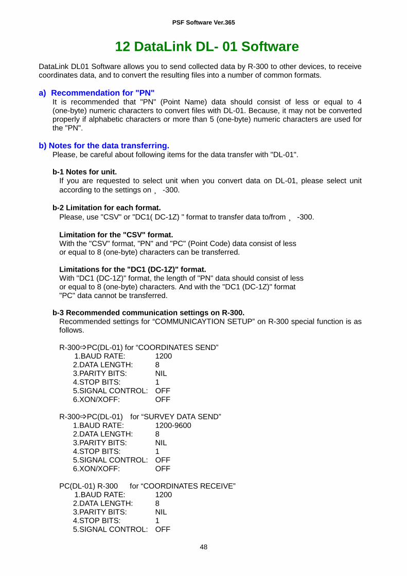
DataLink DL01 Software allows you to send collected data by R-300 to other devices, to receive coordinates data, and to convert the resulting files into a number of common formats. a) Recommendation for "PN"
It is recommended that "PN" (Point Name) data should consist of less or equal to 4 (one-byte) numeric characters to convert files with DL-01. Because, it may not be converted properly if alphabetic characters or more than 5 (one-byte) numeric characters are used for the "PN".
b) Notes for the data transferring.
Please, be careful about following items for the data transfer with "DL-01". b-1 Notes for unit.
If you are requested to select unit when you convert data on DL-01, please select unit according to the settings on R-300.
b-2 Limitation for each format.
Please, use "CSV" or "DC1( DC-1Z) " format to transfer data to/from R-300. Limitation for the "CSV" format. With the "CSV" format, "PN" and "PC" (Point Code) data consist of less or equal to 8 (one-byte) characters can be transferred. Limitations for the "DC1 (DC-1Z)" format. With "DC1 (DC-1Z)" format, the length of "PN" data should consist of less or equal to 8 (one-byte) characters. And with the "DC1 (DC-1Z)" format "PC" data cannot be transferred.
b-3 Recommended communication settings on R-300.
Recommended settings for “COMMUNICAYTION SETUP” on R-300 special function is as follows. R-300 PC(DL-01) for “COORDINATES SEND” 1.BAUD RATE: 1200
2.DATA LENGTH: 8 3.PARITY BITS: NIL 4.STOP BITS: 1 5.SIGNAL CONTROL: OFF 6.XON/XOFF: OFF
R-300 PC(DL-01) for “SURVEY DATA SEND” 1.BAUD RATE: 1200-9600 2.DATA LENGTH: 8 3.PARITY BITS: NIL 4.STOP BITS: 1 5.SIGNAL CONTROL: OFF 6.XON/XOFF: OFF
PC(DL-01) R-300 for “COORDINATES RECEIVE” 1.BAUD RATE: 1200
2.DATA LENGTH: 8 3.PARITY BITS: NIL 4.STOP BITS: 1 5.SIGNAL CONTROL: OFF

PSF Software Ver.365
49
6.XON/XOFF: OFF
Please note that these settings should be common with DL-01's. b-4 Recommended communication settings on DL-01
To configure DL-01 Communication setting, please read "Configuring the software" in the Help topics of DL-01. And select values as follows. For setting “Type of Device” in the "Settings" panel (Menu—“Edit”--”Settings”), select “PCS-300/R-100(PCS)/R-300(PSF)” for “R-300 PentaxSpecificationFunction” and other setting should be as follows.
(Please note that these settings should be common with R-300's. And if the selection of “Type of Device” is not collect it may result in missing some data.) R-300 PC(DL-01)
Bits per second: 1200 (1200-9600 for sending "SURVEY DATA") Databits: 8 Parity: None Stop bits: 1
PC(DL-01) R-300
Bits per second: 1200 Databits: 8 Parity: None Stop bits: 1
c) Note for the Memory capacity Data transfer failure from DL01 to R-300 may cause reduction of memory capacity. If memory capacity becomes less, please back up required data first, and then initialize coordinates data. To initialize coordinates data, turn on the instrument while pressing [F2]+[F5]+[ON/OFF] keys, and take your finger off from [ON/OFF] again. After you see the message "COORD. DATA INITIAL", press [F5] key. Then the message "Please, wait" is displayed. When it is completed, the panel of Electronic Vial is displayed.

PSF Software Ver.365
50
d) Difference between CSV format on “PentaxSpecialFunction” and “PowerTopoLite”
CSV file format from R-300 “PentaxSpecialFunction” version is slightly different from “PowerTopoLite” version as follows. Type of software version Format R-300 “PentaxSpecialFunction” version
PN,X,Y,Z,Code
R-300 “PowerTopoLite” version PN,X,Y,Z,Code,
At the end of each line of CSV file output by “PowerTopoLite”, there is "," as shown above.
e) Note on converting CSV file When you attempt to convert CSV file from R-300 by DL-01, please note that it may not succeed if CSV data type is not correct. After [CONVERT] button is clicked on DL-01 then “CSV files from PCS/R-100 (*.*)”is selected for the type of file,“CSV Import Option” will be appear.
In the case of CSV data doesn't have “CODE” field, please select “PN XY” or “PN XYZ” from following four types for the “type” of data on the “CSV Import Option” panel.
PN XY (Code) PN XYZ(Code) PN XY PN XYZ
f) For more information to work with DL-01, please refer to the "help" file after the installation.

PSF Software Ver.365
51
PENTAX Industrial Instruments Co., Ltd. 2-5-2, Higashi-Oizumi, Nerima-ku,
Tokyo, 178-0086, Japan Tel:+81-3-5905-1222 Fax:+81-3-5905-1225
CERTIFIED ISO 9001 & 14001 E-mail: [email protected] Member symbol of the Japan Surveying Instruments Manufacturers’ Association representing the high quality surveying products.
102002 First edition TS01101EB2