Embed Size (px)
DESCRIPTION
electronic schematic diagram
Citation preview

JIWA DAN RAGA Soul &
Basket

UNIT 4: 2D DRAFTING APPLICATION
4.1 ELECTRONIC CIRCUIT DIAGRAM4.2 FUNCTIONAL BLOK DIAGRAM
4.3 PIPING AND INSTRUMENTATION DIAGRAM

ELECTRONIC CIRCUIT DIAGRAM

LEARNING OUTCOMES
After completing the unit, students should be able to:
Read and explain the most widely used electronics symbols and circuit and diagrams.
Demonstrate proficiency in drawing schematic diagrams, connection diagrams, block diagrams and logic diagrams.

ELECTRONIC CIRCUIT DIAGRAM
Electronic products are made of numerous different types of electronic components. Each of these components can be represented symbolically and pictorially.

PCB – COMPONENT DIAGRAM

PCB – CIRCUIT DIAGRAM

ELECTRONIC SYMBOLS

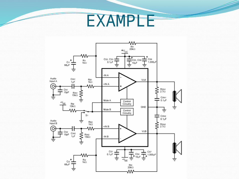
Schematic DiagramSchematic diagrams are used to show how
components are arranged on a circuit board and which components connect with.
It should be noted that the actual location of a component on a circuit board cannot be determined by looking at a schematic diagram.
Schematic shows components and connections but they do not show their actual locations.
EXAMPLE
EXAMPLE
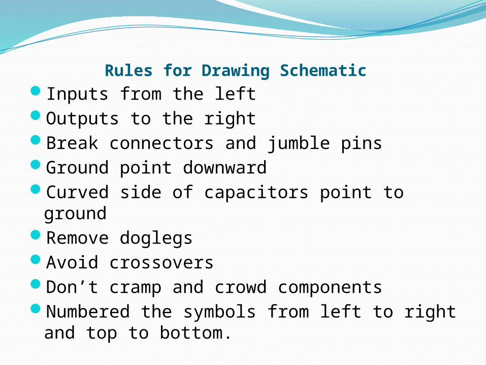
Rules for Drawing Schematic Inputs from the left Outputs to the right Break connectors and jumble pins Ground point downward Curved side of capacitors point to ground Remove doglegs Avoid crossovers Don’t cramp and crowd components Numbered the symbols from left to right and
top to bottom.

Connection Diagrams Connection diagrams are used to show how the
components in an electronic system are connected.
They are used as a guide in assembling electronic system and maintaining electronic equipment.
There are 4 types of connection diagrams :1. Pont-to point diagrams2. Baseline diagrams3. Highway diagrams4. Lineless diagrams

Point to Point DiagramThis type of connection diagram shows the
various terminal connection locations and the routing paths of every wire in electronic system.
Point-to-point diagrams are used primary with simple circuits.
The steps in drawing such a diagram are: 1. Draw the various electronic components in the
actual locations they hold in the circuit. 2. Draw the wire path. 3. Label the wire colors

Example

Baseline DiagramAll wire paths running into a single baseline.
Easier to read and follow than point-to-point diagrams but they can be misleading because they do not show the electronic components in their proper positions.
The steps in drawing such a diagram are :1. Draw a thick line that will serve as the baseline. 2. Draw the electronic components, placing half above
the baseline and half below it. 3. Draw lines from each connection point to the
baseline. The line must be perpendicular to the baseline.
4. Label each wire path with a destination code.

Example

Highway Diagram This type of connection diagram collects
wires that run along similar paths and combines them into groups of wires called “highway”.
As with point-to-point diagrams, in highway diagrams the components are located in the positions they will hold in the actual circuit.

Continue…The steps in drawing such a diagram are :
1. Draw the electronic components in their proper positions.
2. Lightly sketch in the wire paths to determine where potential highways exist.
3. Darken the highways, the lines from the connection points to the highways and components.
4. Label the wire paths with a destination code, component number and wire color.

Example

Lineless Diagrams This type of connection diagram shows the
electronic components with the connection points labeled but it does not show wires.
Instead of wires, the components are accompanied by a table that contains a designation, color and destination code for each wire.
The steps in drawing such a diagram are :1. Draw the electronic components in the
approximate locations they will hold in the actual circuit.
2. Construct the wiring table.

Example

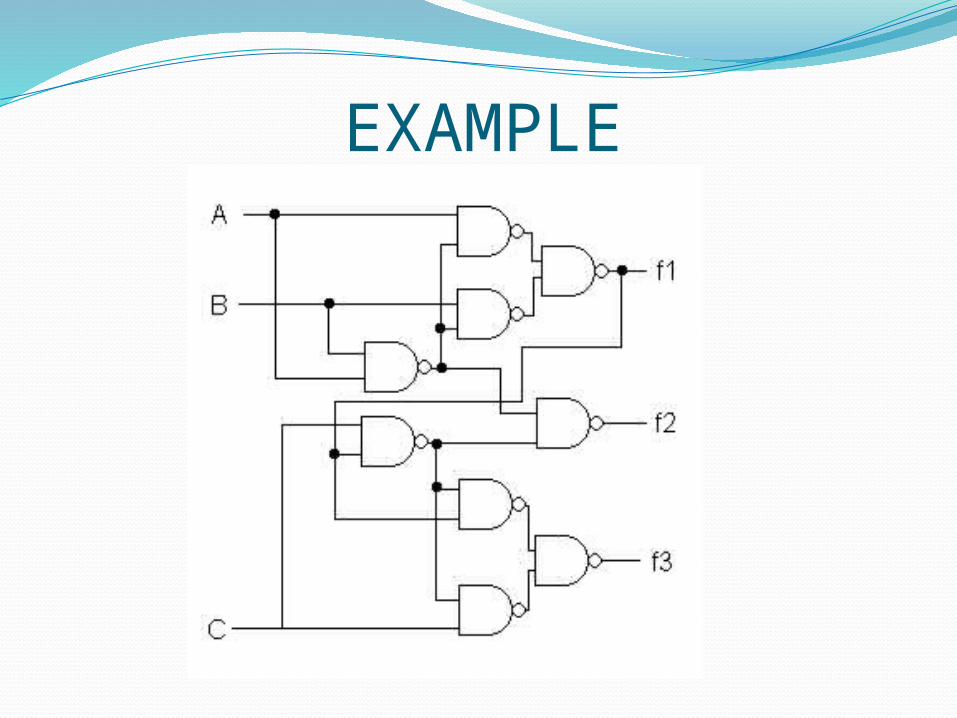
Logic Diagrams Logic diagrams are used in conjunction with
the design of integrated circuits (ICs).
They are most widely used with electronic circuits that are based on the binary numbering concept such as those found in computers.

Example

EXERCISES

EXERCISE 1

EXERCISE 2

Exercise 3