Embed Size (px)
Citation preview
IEEE TRANSACTIONS ON MAGNETICS, VOL. 52, NO. 7, JULY 2016 5400304
Electronic Measurements in an Alternating Magnetic Fieldfor Studying Magnetic Nanoparticle Hyperthermia:
Minimizing Eddy Current HeatingZ. Boekelheide1, Z. A. Hussein2, and S. Hartzell1
1Department of Physics, Lafayette College, Easton, PA 18042 USA2Department of Electrical and Computer Engineering, Lafayette College, Easton, PA 18042 USA
In magnetic nanoparticle hyperthermia therapy and research, accurate sensors are required to monitor the temperature and,potentially, other parameters such as magnetic field or mechanical stress. Conducting materials undergo eddy current heating inan alternating magnetic field (AMF), which is problematic. However, eddy current heating is strongly dependent on the size andgeometry of the conducting part, thus micro- or nano-scale electronics are a promising option. This paper reports calculationsand measurements of self-heating in thin wires (thermocouples) and patterned thin films (resistive thermometers) in an AMF.Thin (40 gauge) type E thermocouples show no significant self-heating compared with the background, while type K and Tthermocouples and thicker (20 gauge) type E, K , and T thermocouples show significant self-heating. A thin film resistive thermometershows no significant self-heating compared with the background when placed parallel to the field, but has significant self-heating whenplaced perpendicular. Thus, electronic measurements in an AMF are feasible with appropriate material properties and geometries,and are a promising possibility for future investigations in magnetic nanoparticle hyperthermia.
Index Terms— Biomagnetics, eddy currents, hyperthermia.
I. INTRODUCTION
MAGNETIC nanoparticle hyperthermia is a promisingcancer treatment in which magnetic nanoparticles are
injected into a tumor and then exposed to an alternatingmagnetic field (AMF), typically in the hundreds of kHz. Heatreleased in this process damages cancerous cells [1], [2];other mechanisms such as mechanical stress from moving orrotating particles may also contribute to cell damage [3]. Heatgeneration can be modeled by the linear response theory forsingle-domain, non-interacting particles [4]; however, thereare significant limitations to this theory, which need furtherstudy [5]. Also in question are the details of heat transfer atcellular length scales [6], [7]. The nature of these thermal andmechanical mechanisms necessitates further study.
To monitor the temperature and magnetic field duringmagnetic nanoparticle hyperthermia therapy, and for fur-ther research into nanoparticle optimization and the mecha-nisms behind cell death, accurate sensors are required. Often,optical rather than electronic temperature sensors are used toavoid eddy current self-heating in conducting parts in theAMF [6], [8]. However, eddy current heating is stronglydependent on the size and geometry of the conducting part,and thus micro- or nano-scale electronics are a promisingpossibility for exploring the behavior of nanoparticles inan AMF.
This paper explores the feasibility of using thin wires(thermocouples) and patterned thin films (resistive ther-mometers) in an AMF based on minimizing self-heating.Thermocouples are ubiquitous and affordable temperaturesensors already in use in many laboratories. Patterned thin
Manuscript received November 6, 2015; revised December 12, 2015;accepted January 3, 2016. Date of publication January 5, 2016; date ofcurrent version June 22, 2016. Corresponding author: Z. Boekelheide (e-mail:[email protected]).
Color versions of one or more of the figures in this paper are availableonline at http://ieeexplore.ieee.org.
Digital Object Identifier 10.1109/TMAG.2016.2515051
film sensors are not as readily produced, but hold promisefor further miniaturization of sensors and fabrication of arraysof sensors. Our results show that electronic measurements arefeasible with both thin wires and patterned thin film sensorsunder certain conditions.
II. THERMOCOUPLES
A. Numerical Calculations
In any conducting media in an AMF, eddy currents areinduced by Faraday’s law, causing Joule heating. This problemcan be solved analytically for symmetric situations [9]. In amagnetic material, hysteresis heating also occurs.
We model a thermocouple wire as a cylindrical wire(radius rmax, height h) aligned along the direction of theuniform, applied AMF: �H = H0eiωt z.
Combining Faraday’s law (∇ × �E = −(∂ �B/∂ t)), Ohm’slaw ( �J f = σ �E), and Ampere’s law in matter (∇ × �H = �J f ),where in linear media �H = (1/μ) �B, we obtain the diffusionequation in �H
∇2 �H = μσ
(∂ �H∂ t
)(1)
for which the solution is a Bessel function J0 with complexargument
�H = Re
[H0
J0((−1)3/4ks)
J0((−1)3/4krmax)eiωt z
](2)
where s is the radial coordinate in the cylindrical coordinatesystem and k = √
ωμσ . Applying Ampere’s law, we find thefree current density �J f
�J f = Re
[k H0(−1)3/4 J1((−1)3/4ks)
J0((−1)3/4krmax)eiωt
]φ. (3)
The instantaneous power dissipated per unit volume by Jouleheating is ρ J 2
f ; to find the average power, we average over a
0018-9464 © 2016 IEEE. Personal use is permitted, but republication/redistribution requires IEEE permission.See http://www.ieee.org/publications_standards/publications/rights/index.html for more information.

5400304 IEEE TRANSACTIONS ON MAGNETICS, VOL. 52, NO. 7, JULY 2016
Fig. 1. Theoretical and experimental heating of thermocouples in an applied AMF, as a function of field. (a) Calculated heating power in thin (40 gauge)thermocouples. (b) Measured steady state �T of thin (40 gauge) thermocouples in air. (Note the break in the y-axis.) (c) Calculated heating power inthick (20 gauge) thermocouples. (d) Measured steady state �T of thick (20 gauge) thermocouples in air.
TABLE I
NUMERICAL PARAMETERS OF THERMOCOUPLES [12], [13]
full cycle in time and integrate over the volume
〈PJoule〉 = 2πhρ f∫ rmax
s=0
∫ 1/ f
t=0J 2
f s ds dt . (4)
The calculated power depends on the experimental parametersand material properties of the wire, given in Table I.
We numerically calculated the power dissipated in copper,constantan, chromel, and alumel. Pairs of these wires makeup thermocouples of type T , K , and E . For the first three,μr = μ/μ0 = 1, so the power is proportional to H 2
0 and theresistivity ρ = 1/σ solely determines the heating power.
Alumel is ferromagnetic, saturating around μ0 H = 0.001 T,with Bsat = 0.1865 T at room temperature [10]. To incorporatethis behavior into our model, for each value of H0, we use
μr = Bsat/(μ0 H0). Then the eddy current heating power isno longer simply proportional to H 2
0 .In addition to eddy current heating, there is additional
heating due to magnetic hysteresis in magnetic materials [11]
〈PHysteresis〉 =[∮
Bd H
]f[πr2
maxh].
For alumel,∮
Bd H = 143 J/m3 [10].1 This adds a constantterm to the power for fields large enough to fully saturate thewhole volume of the wire.2
The power generated in type T , K , and E thermocoupleswas found by summing the heating power from individualwires in the combinations given in Table I. This is shownas a function of H0 in Fig. 1(a) and (c) for two sizesof wires (40 and 20 gauge). Power is much larger in the thickwires, in which large eddy currents develop, than in the thinwires. In the thin thermocouples, type K shows the largestpower due to hysteresis heating of the alumel. The hysteresispower is largely constant in H0 and dominates because it isnot size-dependent. Type T shows the next highest power, dueto the high conductivity of the copper wire. Type E shows thelowest power. The three types of thick thermocouples showmuch more similar heating, and all follow an approximatelyH 2
0 profile. Type T shows the greatest heating, followed bytype K , and again type E has the least heating power.
B. Experimental Results
Type T , K , and E thermocouples (Omega) of two sizes(40 and 20 gauge) were placed in an AMF supplied by
1The sample in [10] was a toroid and our sample is a wire magnetizedalong the long axis; the demagnetization factor in both cases is negligible.
2For μ0 H0 ≥ 0.008 T, the full volume of the wire becomes saturated forboth 20 and 40 gauge wires, so heating was only calculated for alumel atapplied fields greater than this.

BOEKELHEIDE et al.: ELECTRONIC MEASUREMENTS IN AN AMF FOR STUDYING MAGNETIC NANOPARTICLE HYPERTHERMIA 5400304
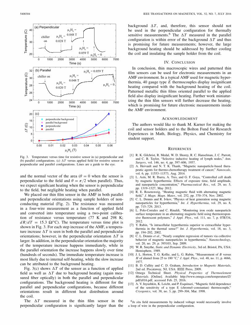
Fig. 2. (a) Resistive sensor mounted on sensor holder. (b) Resistive sensorin coil for measurement in the parallel configuration. In the perpendicularconfiguration, a different sensor holder is used and is inserted betweentwo of the coil turns.
an Ambrell EasyHeat 9 kW induction heater. A home-built,water-cooled solenoidal coil was used [shown in Fig. 2(b)]at a frequency of 235 ± 5 kHz. The magnetic field wascalibrated with a Fluxtrol alternating magnetic field probe suchthat Brms = (0.000143 × I [A]) T. We used H0 = √
2Hrmsto compare theoretical and experimental results.3 Thethermocouple was inserted 0.05 m extended into the coil,parallel to the field, and the voltage was monitored with amultimeter and recorded by Labview. The coil-cooling chillerwas turned ON and the temperature was allowed to stabilize,then the coil current was turned ON and the temperaturewas allowed to stabilize again. The steady-state temperatureincrease �T is shown as a function of H0 in Fig. 1.
The thick (20 gauge) thermocouples all showed a large �T .The trends are similar to the calculated power: type T hadthe largest �T , followed by type K and type E . At low H0,type K had the largest �T , presumably due to hysteresisheating.
3The signal is not a perfect sine wave, so the rms value is a better measureof the field.
For the thin (40 gauge) thermocouples, type K shows thegreatest �T , similar to the power calculation. The thin type Tthermocouple has a very low �T ; although the high electricalconductivity of copper leads to a high calculated powergenerated by eddy currents, the high thermal conductivity ofcopper means that this heat is dissipated more quickly. Thelowest �T is seen in the type E thermocouple.
Some of the temperature increase is due to backgroundheating, i.e., heating from the large current passing throughthe coil. This background �T was measured with a fiber-optic temperature sensor (Opsens OTG-M170) under the sameexperimental conditions. The �T measured in the thin type Ethermocouple is within the error of what is seen in the fiberoptic sensor, suggesting that the thin type E thermocouplehas negligible self-heating in the AMF. The �T measuredin the thin type T thermocouple is slightly higher than this.This suggests that a 40 gauge type E thermocouple is anappropriate choice for measuring temperature in an AMF envi-ronment similar to our environment (235 000 Hz, maximumμ0 H0 = 0.059 T) and a 40 gauge type T thermocouple maybe appropriate for somewhat smaller f and H0. Furthermore,40 gauge chromel or constantan wires could be used in otherelectronic measurements in such an AMF with negligibleeffects due to eddy currents.
Further studies of thermocouples should examine self-heating effects when the thermocouples are inserted intowater, which would more closely approximate actual magneticnanoparticle hyperthermia conditions, in which the tempera-ture sensor is typically either inserted in a vial of liquid withnanoparticles dispersed in it during a lab experiment, or placedon living tissue to monitor the temperature during therapy.
III. PATTERNED THIN FILMS
Eddy current heating is related to the size and geometry ofthe conducting piece, thus microfabricated thin film sensorscould have reduced heating compared to macroscopic wires.Microfabricated sensors are also advantageous because theyare small and scalable, and could ultimately be incorporatedinto arrays of sensors, which could measure, for example, themagnetic field and temperature of an array of samples on a2-D grid. Microfabricated thin films could also be used forother measurements, for example capacitive force sensors tostudy the mechanical effect of nanoparticles on cells.
We created a thin film resistive sensor, shown in Fig. 2.The film is 500 Å Au with 145 Å Cr sticking layer on aglass slide, patterned with photolithography to form a 9050 meander resistor with linewidth 176 μm and four contacts fora resistance measurement.4,5
The eddy currents in a well-defined loop of thin wire can becalculated from Faraday’s law. The power generated by Jouleheating is
〈PJoule〉 = [Aμ0 H0ωcosθ ]2
2R(5)
where R is the resistance of the loop, A is the area enclosed bythe loop of wire, and θ is the angle between the applied field
4Using a Si wafer (10–20 -cm) substrate resulted in eddy currents inthe Si, leading to significant Joule heating which dominated the signal.
5Pt may be preferable for a resistive thermometer because of its hightemperature coefficient of resistance; its higher resistance would also reduceeddy current heating. Au was used in this case because of its ease of depositionusing a thermal evaporator. We may use Pt in future work.
5400304 IEEE TRANSACTIONS ON MAGNETICS, VOL. 52, NO. 7, JULY 2016
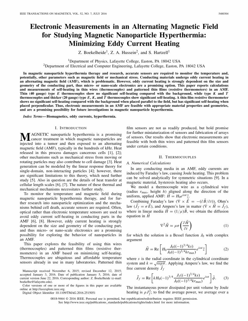
Fig. 3. Temperature versus time for resistive sensor in (a) perpendicular and(b) parallel configurations. (c) �T versus applied field for resistive sensor inperpendicular and parallel configurations. Lines are a guide to the eye.
and the normal vector of the area (θ = 0 when the sensor isperpendicular to the field and θ = π/2 when parallel). Thus,we expect significant heating when the sensor is perpendicularto the field, but negligible heating when parallel.
We placed our thin film sensor in the AMF in both paralleland perpendicular orientations using sample holders of non-conducting material (Fig. 2). The resistance was measuredin a four-wire measurement as a function of applied fieldand converted into temperature using a two-point calibra-tion of resistance versus temperature (77 K and 298 K;d R/dT = 15.3 /°C). The temperature versus time plot isshown in Fig. 3. For each step increase of the AMF, a tempera-ture increase �T is seen in both the parallel and perpendicularorientations; however, in the perpendicular orientation �T islarger. In addition, in the perpendicular orientation the majorityof the temperature increase happens immediately, while inthe parallel orientation the increase happens slowly over time(hundreds of seconds). The immediate temperature increase ismost likely due to internal self-heating, while the slow increasecan be attributed to the background heating.
Fig. 3(c) shows �T of the sensor as a function of appliedfield as well as �T due to background heating (again mea-sured fiber optically) in both the parallel and perpendicularconfigurations. The background heating is different for theparallel and perpendicular configurations, because differentorientations result in different heat distribution aroundthe coil.
The �T measured in the thin film sensor in theperpendicular configuration is significantly larger than the
background �T , and, therefore, this sensor should notbe used in the perpendicular configuration for thermallysensitive measurements.6 The �T measured in the parallelconfiguration is within error of the background �T and thusis promising for future measurements; however, the largebackground heating should be addressed by further coolingthe coil and insulating the sample holder from the coil.
IV. CONCLUSION
In conclusion, thin macroscopic wires and patterned thinfilm sensors can be used for electronic measurements in anAMF environment. In a typical AMF used for magnetic hyper-thermia, 40 gauge type E thermocouples display insignificantheating compared with the background heating of the coil.Patterned metallic thin films oriented parallel to the appliedfield also display insignificant heating. Further work miniatur-izing the thin film sensors will further decrease the heating,which is promising for future electronic measurements insidethe AMF environment.
ACKNOWLEDGMENT
The authors would like to thank M. Karner for making thecoil and sensor holders and to the Bolton Fund for ResearchExperiences in Math, Biology, Physics, and Chemistry forstudent support.
REFERENCES
[1] R. K. Gilchrist, R. Medal, W. D. Shorey, R. C. Hanselman, J. C. Parrott,and C. B. Taylor, “Selective inductive heating of lymph nodes,” Ann.Surgery, vol. 146, no. 4, pp. 597–606, 1957.
[2] A. Hervault and N. T. K. Thanh, “Magnetic nanoparticle-based thera-peutic agents for thermo-chemotherapy treatment of cancer,” Nanoscale,vol. 6, pp. 11553–11573, Aug. 2014.
[3] L. Asín, M. R. Ibarra, A. Tres, and G. F. Goya, “Controlled cell deathby magnetic hyperthermia: Effects of exposure time, field amplitude,and nanoparticle concentration,” Pharmaceutical Res., vol. 29, no. 5,pp. 1319–1327, May 2012.
[4] R. E. Rosensweig, “Heating magnetic fluid with alternating magneticfield,” J. Magn. Magn. Mater., vol. 252, pp. 370–374, Nov. 2002.
[5] C. L. Dennis and R. Ivkov, “Physics of heat generation using magneticnanoparticles for hyperthermia,” Int. J. Hyperthermia, vol. 29, no. 8,pp. 715–729, 2013.
[6] L. Polo-Corrales and C. Rinaldi, “Monitoring iron oxide nanoparticlesurface temperature in an alternating magnetic field using thermorespon-sive fluorescent polymers,” J. Appl. Phys., vol. 111, no. 7, p. 07B334,2012.
[7] Y. Rabin, “Is intracellular hyperthermia superior to extracellular hyper-thermia in the thermal sense?” Int. J. Hyperthermia, vol. 18, no. 3,pp. 194–202, 2002.
[8] C. L. Dennis et al., “Nearly complete regression of tumors via collectivebehavior of magnetic nanoparticles in hyperthermia,” Nanotechnology,vol. 20, no. 29, p. 395103, Sep. 2009.
[9] W. R. Smythe, Static and Dynamic Electricity, 3rd ed. Bristol, PA, USA:Hemisphere, 1989.
[10] J. L. Horton, T. G. Kollie, and L. G. Rubin, “Measurement of B versusH of alumel from 25 to 180 °C,” J. Appl. Phys., vol. 48, no. 11, p. 4666,1977.
[11] B. D. Cullity and C. D. Graham, Introduction to Magnetic Materials,2nd ed. Piscataway, NJ, USA: IEEE Press, 2009.
[12] Omega Technical Sheet. Physical Properties of ThermoelementMaterials. [Online]. Available: http://www.omega.com/temperature/Z/pdf/z016.pdf, accessed Feb. 25, 2016.
[13] A. V. Inyushkin, K. Leicht, and P. Esquinazi, “Magnetic field dependenceof the sensitivity of a type E (chromel–constantan) thermocouple,”Cryogenics, vol. 38, no. 3, pp. 299–304, Mar. 1998.
6In situ field measurements by induced voltage would necessarily involvea loop of wire in the perpendicular configuration.