Embed Size (px)
Citation preview
Electromechanical Coupled Non-linear Dynamics for Micro Plate Simply supported on four Sides
Libo Sun College of Environmental and Chemical Engineering,
Hebei Key Laboratory of Applied Chemistry
Yanshan University
Qinhuangdao, China, 066004
Lizhong Xu Mechanical Engineering Institute
Yanshan University
Qinhuangdao, China, 066004 [email protected]
Abstract—Dynamic characteristic of the micro plate under the micro scale effect shows non-linear features, traditional linear analysis methods can not satisfy the design precision of MEMS system, and non-linear dynamics analysis method provides an effective solution. In this paper, based on the small deflection theory and electrostatics theory, take typical boundary condition of the micro plate simply supported on four sides as example, the basic differential equation of lateral vibration is established, using Linz Ted-Poincare method, displacement and time course of forced vibration, time responses of forced vibration are calculated. The research results provide theoretical basis for optimizing the system parameters, improving the ability to resist interferences and increases the reliability.
Keywords- micro plate; MEMS; non-linear dynamics; small deflection theory; Linz Ted-Poincare method
I. INTRODUCTION
Within the microscopic scale, machinery can be divided into small machinery dimensions of 1~10 mm, micro machinery dimensions of 1μm~1mm, and nano machinery of 1nm~1μm according to the different characteristics scale. Micro-electromechanical systems is called Micro machine and MEMS system, which generally consists of micro machinery and nano machinery, but not the macro machinery be miniaturized simply. Micro-electromechanical system (MEMS) can be described as micron even smaller order micro-component or micro system made up of electron or mechanical component, and its processing method and driving principle are different from macroscopic machine. Such devices are new technology products which can realize higher accuracy, more convenient and efficient, cheaper and better energy saving micro operation, also, can feel, understand, reform and control objective world. MEMS have potential applications in automatic control, mobile communication, aerospace instrument and biomedical engineering field [1~3].
Micro components are important parts, which are composed of micro agencies and micro-electromechanical systems. Although, structure of the micro components is generally simple, we can use their displacement, deformation and movement to realize the function of micro sensor and micro actuator. Main form of the micro components are consist of micro plate, micro beam, micro film and micro hinge etc. Among them, as a typical structural element, the
micro plate has been widely used in MEMS technology, such as micro valve, micro pump and micro sensor etc. At present, for the dynamic characteristic of the micro plate, especially under the micro scale effect, the research on the vibration of electromechanical coupled micro plate is still very few. However, these researches would have a positive impact on structural design, optimization, control and improving the stability and reliability of MEMS devices and systems.
In the micro plate electromechanical coupled system, we utilize the electrostatic field which has been applied on fixed driving plate and micro mobile plate to generate electrostatic field driving force. The electrostatic field driving force would cause the mutual attraction between the fixed driving plate and the micro mobile plate, the micro mobile plate would displace relatively due to the attraction, under alternating electric field force, and the high frequency vibration of the micro mobile plate would be generated. Displacement of the micro mobile plate would be changed with the changes of the electrostatic field driving force frequencies, when driving frequency closes to natural frequency of the micro mobile plate, the micro mobile plate would resonate, by this time, the displacement maximum of the micro mobile plate is reached.
In this paper, based on the small deflection theory and electrostatics theory, the electromechanical coupled dynamics model is established, formulas of the static and dynamic electric field force are derived, and moreover, the basic differential equation of lateral vibration is established by using elasticity theory. Take typical boundary condition of the micro plate as example, displacement and time course of forced vibration, time responses of forced vibration are calculated with the aid of computing simulation to achieve the systemic analysis and design, which provides theoretical basis for optimizing the system parameters, improving the ability to resist interferences and increases the reliability.
II. DYNAMIC MODEL OF ELECTROMECHANICAL COUPLED MICRO PLATE
Fig.1 illustrates a dynamic model of electromechanical coupled micro plate, consisting of mechanical system, electrical system, and coupled part. The mechanical system is a micro plate subjected to electric field force which distributes equally on the micro plate. The upper is the micro mobile plate, it is the main object of study, we call it micro plate, the below
The assistances from the National Natural Science Foundation of China (No. 51275441) and Science Research Plan of Hebei Education Department (No. Z2012031) for this work are heartily acknowledged.
Proceedings of 2012 International Conference on Mechanical Engineering and Material Science (MEMS 2012)
© 2012. The authors - Published by Atlantis Press 210

is the fixed driving plate, the DC electrostatic bias voltage is applied between the two plates. The electrical source, resistance and capacitance construct electrical system. Mechanical system and electrical system achieve electromechanical coupled state by electric field force. The micro plates system obey the basic assumptions of elastic thin plat small deflection theory, as follows
Middle surface normal hypothesis, that is to say, the middle surface normal maintains a line and always be vertical to the middle surface throughout the process of deformation.
The normal stress of the middle surface is neglected.
Without the deformation inside the middle surface.
Inertial forces should be included in but moment of inertia should be ignored [9].
x
z
a
( , , )q x y t
( , , )et w x y t
h
et
o
0v
y
b
Fig.1 Dynamic model of electromechanical coupled micro plate
The micro plate simply supported on four sides is widely used in micro pump membrane; fig.2 illustrates the Cartesian coordinate system of micro plate simply supported on four sides.
x
y
o
a
b
Fig.2 Cartesian coordinate system of micro plate simply supported on four
sides
III. DYNAMIC DIFFERENTIAL EQUATIONS
Based on the thin plate deflection theory, the control differential equation of the deflection surface subjected to electric field force is given by
4 4 2 22 2
2 2 4 2 2
4
4( , , )
2 qx y t
D Dh hw w w ww
Dx y y t tw
x
(1)
Here w is transverse displacement of the micro plate, D is the flexural rigidity of the micro plate material, (e.g. 3 212(1 )tD E h , where Et and are the elastic modulus and Poisson ratio of the micro plate material respectively, and h is the thickness of the micro plate), 2 2 is biharmonic operator, 2 2 4 4 4 2 2 4 42x x y y , ρ is the mass density of the micro plate, and q is the load per unit area above the micro plate. When q(x, y, t) is equal to 0, the free vibration differential equation of the micro plate is obtained.
When the sinusoidal alternating voltage is applied on the system, (e.g. 0v cosis eU t , U0 is excitation voltage amplitude, ωe is excitation voltage frequency), because of positive and negative values canceling each other,the voltage only has effect on the dynamic responses, but not the static displacement. According to reference [10], the dynamic electrostatic force per unit area caused by the voltage fluctuation can be calculated as follows
20 0 0 0cos ( + / )e c rq U A t t w d (2)
Here ε0 is the permittivity of free space, equal to 12
8.85 100 C2 N-1 m-2, εr is the relative dielectric
constant of the upper micro plate coating, dc is the thickness of the upper micro plate coating, t0 is the initial clearance between two micro plates, and w0 is the static average displacement along z-axis of micro plate.
The basic equation of the forced vibration for micro plate under the harmonic voltage exciting is
2 2 2 2 20 0 0 0sin ( + / )e c rD w h w t U A t t w d (3)
IV. NON-LINEAR FORCED VIBRATION
When apply the periodic exciting voltage between the micro plate and the fixed driving plate, the dynamic electrostatic force per unit area caused by the voltage fluctuation can be calculated by using Eq. (2). Introducing the dimensionless small parameter ε, as the static average displacement 0w is small, 0 0 c rw t d can be taken as small
parameter ε, and the parameter is assumed to be small, 0 0 / , 0 1c rw t d . Let the exiting force amplitude engendered by exciting voltage and small parameter ε is the same order of magnitude. Then, Eq. (2) can be defined in Taylor series form (neglect high-order terms) as follows
2 2 20 0 0 0
3 30 0 0 0
3
( / ) ( / )c r c r
U w U wq
t w d t d w
2 30 0 0 0 0
4 20 0 0 0
6 cos
( / ) ( )e
c r c r
U w U E t
t d w t w d
(4)
Substituting equation (4) into equation (1), neglect high-order terms, and let ( , , ) ( , ) ( )w x y t x y q t , the non-linear dynamical equation can be obtained
2 21 20 0( ) ( ) ( ) ( ) cos e
b bq t q t q t q t F t
h h
(5)
Where 2 31 0 0 0 03 ( / )c rb U t d w ,2 2 4
2 0 0 0 06 ( / )c rb U t d w , 2
3 0 0 0 0( )c rb U t w d , 0 3 0F b E h ,
0 0
1( , )
a b
i x y dxdyab
, 2 2
0 0
1( , )
a b
i x y dxdyab
.
When 0 , the Eq. (5) degrades to the linear dynamical equation of derivation system.
211
20 0( ) ( ) cos eq t q t F t (6)
According to reference [11], using the Linz Ted-Poincare method, the solution of the equation can be given as follows
2
0 1 2( , ) ( ) ( ) ( ) ......q t q t q t q t (7)
The initial conditions are
0 0 0
1 1
2 2
(0) , (0) 0
(0) 0, (0) 0
(0) 0, (0) 0
......
iq Q q
q q
q q
(8)
Substituting Esq. (7) and (8) into Eq.(5), and then setting the coefficients with same power of to zero, we obtain the linear equations, then using the initial condition (8) to calculate repeatedly, we get the time solution which has enough precision as follows
2 2 20 0 0 1 1 2 2, cos cos2e eq t B C Q B C t B C t
2 2 23 3 4 5cos3 cos 4 cos5e e eB C t C t C t (9)
Where 2 20 1 0 02B b Q h
3 2 2 2 2 21 2 0 0 0 03 (4 )(9 ) 4e eB b Q hM
2 2 2 2 2 22 1 0 0 0 0( )(9 ) 2e eB b Q hM
3 2 2 2 2 23 2 0 0 0 0( )(4 ) 4e eB b Q hM
8 6 2 4 4 2 60 0 0 014 49 36e e eM
100 0 1 1 0 2 2 0 0 257600 43200 86400eC Q B b Q B b Q B b
6 40 0 1 1 0 2 2 0 0 230580 22935 45870eQ B b Q B b Q B b
4 60 0 1 1 0 2 2 0 0 24092 3069 6138eQ B b Q B b Q B b
2 80 0 1 1 0 2 2 0 0 2220 165 330eQ B b Q B b Q B b
100 0 1 1 0 2 2 0 0 24 3 6Q B b Q B b Q B b hN
8 21 0 0 0 1 2 0 3 2 0 1 2 1129600 43200 115200 57600eC Q Q B b Q B b B b B b
6 40 0 0 1 2 0 3 2 0 1 2 160084 20028 53408 26704eQ Q B b Q B b B b B b
4 6
0 0 0 1 2 0 3 2 0 1 2 18721 2907 7752 3876eQ Q B b Q B b B b B b
2 80 0 0 1 2 0 3 2 0 1 2 1486 162 432 216eQ Q B b Q B b B b B b
100 0 0 1 2 0 3 2 0 1 2 19 3 8 4Q Q B b Q B b B b B b hN
8 22 0 0 0 2 2 0 0 2 1 1 3 121600 21600 14400 14400eC Q Q B b Q B b B b B b
6 40 0 0 2 2 0 0 2 1 1 3 126214 26214 17476 17476eQ Q B b Q B b B b B b
4 60 0 0 2 2 0 0 2 1 1 3 14914 4914 3276 3276eQ Q B b Q B b B b B b
2 80 0 0 2 2 0 0 2 1 1 3 1306 306 204 204eQ Q B b Q B b B b B b
100 0 0 2 2 0 0 2 1 1 3 16 6 4 4Q Q B b Q B b B b B b hN
8 23 0 0 0 1 2 0 3 2 2 14800 9600 6400eC Q Q B b Q B b B b
6 40 0 0 1 2 0 3 2 2 16492 12984 8656eQ Q B b Q B b B b
4 60 0 0 1 2 0 3 2 2 11827 3654 2436eQ Q B b Q B b B b
2 80 0 0 1 2 0 3 2 2 1138 276 184eQ Q B b Q B b B b
100 0 0 1 2 0 3 2 2 13 6 4Q Q B b Q B b B b hN
8 2 6 44 0 0 0 2 2 3 1 0 0 0 2 2 3 12700 3600 3783 5044e eC Q Q B b B b Q Q B b B b
4 6 2 80 0 0 2 2 3 1 0 0 0 2 2 3 11197 1596 117 156e eQ Q B b B b Q Q B b B b
100 0 0 2 2 3 13 4Q Q B b B b hN
2 8 2 6 4 4 6 2 8 105 0 3 2 0 0 0 0 01728 2460 819 90 3e e e eC Q B b hN
12 10 2 8 4 6 6 4 8 2 100 0 0 0 0 04 220 4092 30580 84304 57600e e e e eN
Where ω0 is the natural frequency of the system, ωe is the exciting frequency.
V. ANALYSIS AND DISCUSSIONS OF TYPICAL
EXAMPLE
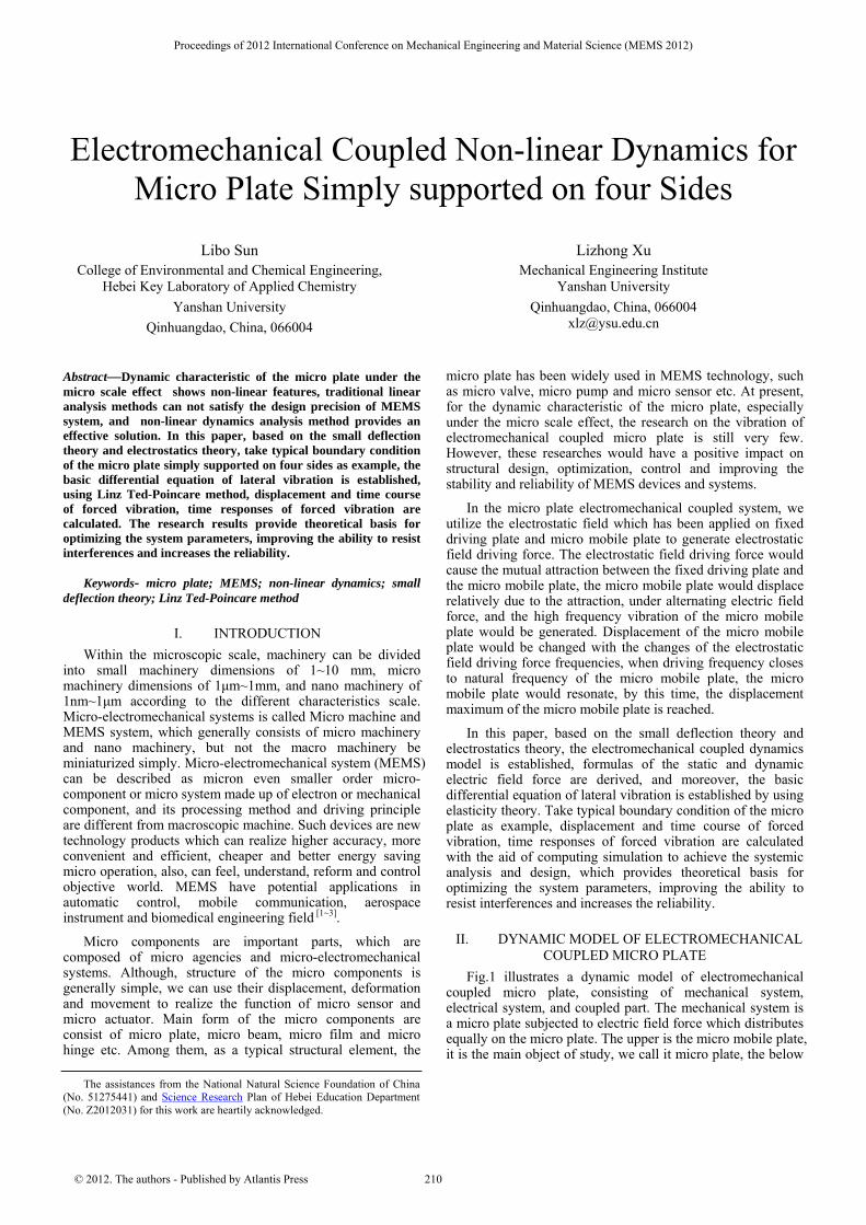
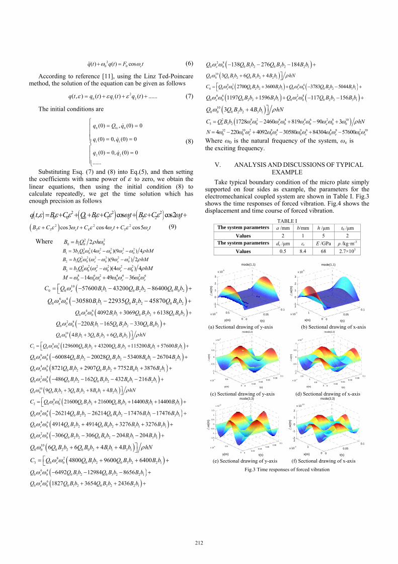
Take typical boundary condition of the micro plate simply supported on four sides as example, the parameters for the electromechanical coupled system are shown in Table I. Fig.3 shows the time responses of forced vibration. Fig.4 shows the displacement and time course of forced vibration.
TABLE I The system parameters a /mm b/mm h /μm t0 /μm
Values 2 1 5 2 The system parameters dc /μm εr E /GPa ρ /kg·m-3
Values 0.5 8.4 68 2.7×10³
0
0.05
0.1
0
0.5
1
x 10-3
-1
0
1
2
3
x 10-5
t(s)
mode(1,1)
y(m)
△w
(m)
0
0.05
0.1
0
1
2
x 10-3
-1
0
1
2
3
x 10-5
t(s)
mode(1,1)
x(m)
△w
(m)
(a) Sectional drawing of y-axis (b) Sectional drawing of x-axis
00.02
0.040.06
0.080.1
0
0.5
1
x 10-3
-1
-0.5
0
0.5
1
x 10-8
t(s)
mode(2,2)
y(m)
△w
(m)
00.02
0.040.06
0.080.1
0
0.5
1
1.5
2
x 10-3
-1
-0.5
0
0.5
1
x 10-8
t(s)
mode(2,2)
x(m)
△w
(m)
(c) Sectional drawing of y-axis (d) Sectional drawing of x-axis
00.02
0.040.06
0.080.1
0
0.5
1
x 10-3
-1.5
-1
-0.5
0
0.5
1
1.5
x 10-10
t(s)
mode(3,3)
y(m)
△w
(m)
0
0.05
0.1
0
1
2
x 10-3
-2
-1
0
1
2
x 10-10
t(s)
mode(3,3)
x(m)
△w
(m)
(e) Sectional drawing of y-axis (f) Sectional drawing of x-axis
Fig.3 Time responses of forced vibration
212

0 0.02 0.04 0.06 0.08 0.1-0.5
0
0.5
1
1.5
2
2.5
3x 10
-5
t(s)
△w
(m)
mode(1,1)
0 0.02 0.04 0.06 0.08 0.1
-8
-6
-4
-2
0
2
4
6
8x 10
-9
t(s)△
w(m
)
mode(2,2)
(a) Mode (1, 1) (b) Mode (2, 2)
0 0.02 0.04 0.06 0.08 0.1-1.5
-1
-0.5
0
0.5
1
1.5x 10
-10
t(s)
△w
(m)
mode(3,3)
(c) Mode (3, 3)
Fig.4 Displacement and time course of forced vibration
Eq. (9) is utilized for the analysis of the non-linear forced response of the electromechanical coupled micro plate. The forced response corresponding to the first three modes are given in Fig.3 and Fig.4, the working voltage between two micro plates U0=7.0v, the exciting frequency
20 rad se .The maximum dynamic displacement occurs at point (x=1mm, y=1mm). From Fig.3 and Fig.4, following observations are worth noting:
The region surrounded by displacement-time curve of mode 1is the largest, and frequencies of mode 2 and mode 3increase very significant, the regions surrounded by displacement-time curve are smaller.
For different modes, the peak position and the vibration period are different, and the natural frequencies of higher modes are relatively large, the vibration periods decrease.
The dynamic responses of non-linear dynamics appear asymmetric, and the displacement-time curve is no longer symmetrical about the system equilibrium position, this phenomenon is most obvious in the first mode. This is due to considering the non-linear factor of electrostatic force in the non-linear solution, and which causes the DC and harmonic component to the vibration response.
For the micro plate simply supported on four sides, the boundary condition and material geometry are
symmetry, the time response curve is symmetry too, the point of maximum displacement occurs at the center of the moving micro plate.
VI. CONCLUSIONS In this paper, non-linear dynamic responses of
electromechanical coupled micro plate simply supported on four sides are analyzed. Control differential equation and vibration mode function for electromechanical coupled micro plate simply supported on four sides are presented. Defining the dynamic electrostatic force per unit area in Taylor series form, the forced non-linear dynamic equation is obtained. These works can provide theoretical basis for the parameters calculation of dynamic design and manufacture of MEMS typical components driving by electrostatic force.
The time dynamic responses are under the condition of no damp, which is the analysis result of ideal condition, and this work can provide a theoretical basis for the dynamic analysis of damping system.
REFERENCES [1] Xu L, Sun L. Electromechanical coupled non-linear vibration of the
micro plate. Proceedings of the Institution of Mechanical Engineers Part C-Journal of Mechanical Engineering Science, 2010, 224(C6): 1383-1396
[2] Libo Sun, Lizhong Xu. Non-linear forced vibration for an electromechanical coupled micro plate simple supported at three sides and free at one side. 2009IEEE International Conference on Mechatronics and Automation,Changchun, 2009, 42(3): 4289-4293.
[3] Zafer Kazanc, Zahit Mecitoglu. Non-linear dynamic behavior of simply supported laminated composite plates subjected to blast load. Sound and Vibration, 2008,19(3):883~897
[4] Minhang Bao, Heng Yang. Squeeze film damping in MEMS. Sensors and Actuators, 2007,(136):3~27
[5] Liang YC, et al. A neural-network-based method of model reduction for the dynamic simulation of MEMS.J Micromechanics and Micro engineering, 2001, 11(3):226~233.
[6] Cleland A N, Roukes M L. Fabrication of high frequency nanometer scale mechanical resonators from bulk Si crystals. Appl Phys Lett, 1996,69(18):2653~2655
[7] Yang W.The mechanics characteristic of micro-nanoscale. World Sci-tech R & D, 2004, 26(4):2~6.
[8] Wang chao,et al.Non-linear analysis of mechanical problems in MEMS application. Machine development, 2005, 34(8):18~20.
[9] Cao Zhiyuan.Vibration theory of plates and shells. Beijing: China's railway press, 1989:13~25.
[10] Herbert H W, James R M.Electromechanical dynamics. Beijing: China Machine Press, 1982:33~39.
[11] Liu Yanzhu.Mechanic of vibrations. Beijing:Higher Education Press, 1998:201~206.
213


![Performance and Stability Limitations of Admittance-Based ......electromechanical haptic interface dynamics, a coupled human impedance model [17], and the rendered virtual admittance](https://img.dokumen.tips/doc/110x75/60e2c1820229ae2f2a082f23/performance-and-stability-limitations-of-admittance-based-electromechanical.jpg)