Embed Size (px)
Citation preview

Textbook TP 601
Festo Didactic
093611 en
ElectrohydraulicsBasic Level
093611_cover_textbook_tp601_en.indd 1 01.04.2005 08:41:39
Order No.: 093611
Edition: 03/2006
Authors: C. Löffler, D. Merkle, G. Prede, K. Rupp, D. Scholz
Graphics: Doris Schwarzenberger
Layout: 30.05.2006, Beatrice Huber
© Festo Didactic GmbH & Co. KG, 73770 Denkendorf, Germany, 2006
Internet: www.festo-didactic.com
e-mail: [email protected]
The copying, distribution and utilization of this document as well as the
communication of its contents to others without expressed authorization is
prohibited. Offenders will be held liable for the payment of damages. All rights
reserved, in particular the right to carry out patent, utility model or ornamental
design registration.
© Festo Didactic GmbH & Co. KG • TP 601 3
Preface______________________________________________________________ 5
1. Introduction___________________________________________________ 7
1.1 Areas of application of electrohydraulics ____________________________ 7
1.2 Basic control engineering terms ___________________________________ 9
1.3 Hydraulic and electrohydraulic control systems _____________________ 15
1.4 Advantages of electrohydraulic control systems _____________________ 21
2. Fundamentals of electrical technology____________________________ 23
2.1 Direct current and alternating current _____________________________ 23
2.2 Ohm's Law ___________________________________________________ 24
2.3 Mode of operation of a solenoid__________________________________ 26
2.4 Mode of operation of a capacitor _________________________________ 28
2.5 Mode of operation of a diode ____________________________________ 29
2.6 Measurement in electrical circuits ________________________________ 30
3. Components and assemblies in the electrical signal control section ___ 35
3.1 Power supply unit _____________________________________________ 35
3.2 Push button and control switches ________________________________ 36
3.3 Sensors for measuring displacement and pressure___________________ 38
3.4 Relays and contactors __________________________________________ 48
3.5 Programmable logic controllers __________________________________ 53
3.6 Overall structure of the signal control section _______________________ 54
4. Solenoid actuated directional control valves _______________________ 57
4.1 Exercises ____________________________________________________ 57
4.2 Design and mode of operation ___________________________________ 59
4.3 Designs and hydraulic performance data___________________________ 77
4.4 Performance data of solenoid coils _______________________________ 90
4.5 Electrical connection of solenoid coils _____________________________ 93
5. Design of an electrohydraulic control system ______________________ 97
5.1 Procedure for the development of a control system __________________ 97
5.2 Procedure for the planning of a control system ______________________ 99
5.3 Application example: Design of a sawing machine __________________ 103
5.4 Procedure for the realisation of the control system__________________ 122
Contents

Contents
4 © Festo Didactic GmbH & Co. KG • TP 601
6. Documentation of an electrohydraulic control system ______________ 127
6.1 Function diagram _____________________________________________ 128
6.2 Sequence table ______________________________________________ 137
6.3 GRAFCET____________________________________________________ 139
6.4 Hydraulic circuit diagram ______________________________________ 162
6.5 Electrical circuit diagram _______________________________________ 176
6.6 Terminal connection diagram ___________________________________ 187
7. Safety measures for electrohydraulic control systems ______________ 197
7.1 Dangers and protective measures _______________________________ 197
7.2 Effect of electric current on the human body _______________________ 198
7.3 Measures to protect against accidents with electric current___________ 201
7.4 Control panel and indicating elements____________________________ 202
7.5 Protecting electrical equipment against environmental impact ________ 206
7.6 Safety recommendations for electro-hydraulic systems ______________ 208
8. Relay control systems ________________________________________ 209
8.1 Use of relay control systems in electrohydraulics ___________________ 209
8.2 Direct and indirect actuation____________________________________ 209
8.3 Logic operations _____________________________________________ 213
8.4 Signal storage _______________________________________________ 216
8.5 Delay_______________________________________________________ 222
8.6 Sequence control with signal storage via double solenoid valves ______ 224
8.7 Circuit for evaluating control elements____________________________ 235
8.8 Sequence control system for a sawing machine ____________________ 238
Index _____________________________________________________________ 265
Standards _________________________________________________________ 273
© Festo Didactic GmbH & Co. KG • TP 601 5
Electrohydraulics are in use in numerous areas of industrial automation. To give a
few examples, woodworking machines, machine tools, process engineering plants,
presses, plastics processing machines and conveyor systems worldwide are
operated using electrohydraulic control systems. However, electrohydraulic control
systems are also in use in a wide variety of ways such as in mobile hydraulics which
include agricultural vehicles, road construction or street cleansing.
Changing requirements and technical development have distinctly changed the
appearance of control systems. The relay in the signal control section increasingly
has been replaced by programmable logic controllers in many areas of application in
order to meet the increased need for flexibility. In the power section too, advanced
electrohydraulic control systems feature new concepts adapted to the needs of
industrial practice. To mention just a few keywords such as control block, bus
networks and proportional hydraulics. The close interaction of fluid power
engineering with microelectronics, sensors and information technology leads to
numerous innovations in the area of oil-hydraulic drives and control systems. These
in turn open up new fields of application to electrohydraulics with more challenging
tasks in process control.
As an introduction to the subject, the textbook first of all explains the design and
mode of operation of the components required for the construction of an
electrohydraulic control system. The following chapters describe the procedure for
the planning, design and realisation of electrohydraulic control systems, using fully
detailed examples.
All readers of this book are invited to contribute with tips, suggestions and
constructive criticism in order to improve the book.
March 2006 The authors
Preface

6 © Festo Didactic GmbH & Co. KG • TP 601

© Festo Didactic GmbH & Co. KG • TP 601 7
Hydraulics involves the use of hydraulic fluids. Hydraulic fluids are most commonly
used to perform mechanical work. Mechanical work is necessary in order to carry out
movements and generate forces. The function of hydraulic drives is to convert the
energy stored in hydraulic fluid into kinetic energy.
The following are used as hydraulic drives:
• Cylinders (linear drives) for the generation of straight-linear movements ,
• Motors and semi-rotary actuators drives (rotary drives) to generate rotary
movements.
Hydraulic linear cylinder (Storz Hydrauliksysteme GmbH) and hydraulic motor (Sauer-Danfoss GmbH & Co)
Hydraulic systems are used if high performance levels, excellent heat dissipation,
regular movement, high switching dynamics or extremely high forces are required.
Applications of electrohydraulics can be found both in stationary and mobile
hydraulics. Characteristic of electrohydraulics is the receiving, processing and
output of signals. The valves forming the interface to the power section are also
solenoid actuated.
Important branches of electrohydraulics are:
• Machine building, where electrohydraulic system for example are used to feed
machine tools, for the generation of force for presses or in injection moulding
machine for plastics processing
• Automotive engineering, where electrohydraulic systems are the preferred
option for the actuation of construction machinery or also for the control of
steering mechanisms on agricultural machinery
• Steel and power station construction. Here, electrohydraulic systems are used
for theatre technics, lifting platforms, for the control of locks, weir gates and
movable bridges
1. Introduction
1.1
Areas of application of
electrohydraulics

1. Introduction
8 © Festo Didactic GmbH & Co. KG • TP 601
• Aircraft construction, where for example the actuation of the landing flaps and
rudders is realised electrohydraulically
• Ship building, where for example the rudder or the cargo cranes are controlled
electrohydraulically
In the case of modern CNC controlled machine tools, tools and workpieces are
clamped hydraulically. Feed functions and spindle drives can also be hydraulically
realised.
Rotary indexing machine
Application example
1. Introduction
© Festo Didactic GmbH & Co. KG • TP 601 9
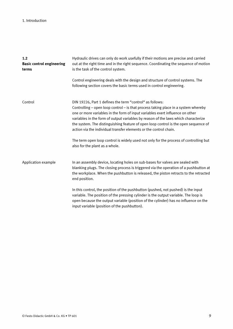
Hydraulic drives can only do work usefully if their motions are precise and carried
out at the right time and in the right sequence. Coordinating the sequence of motion
is the task of the control system.
Control engineering deals with the design and structure of control systems. The
following section covers the basic terms used in control engineering.
DIN 19226, Part 1 defines the term “control“ as follows:
Controlling – open loop control – is that process taking place in a system whereby
one or more variables in the form of input variables exert influence on other
variables in the form of output variables by reason of the laws which characterize
the system. The distinguishing feature of open loop control is the open sequence of
action via the individual transfer elements or the control chain.
The term open loop control is widely used not only for the process of controlling but
also for the plant as a whole.
In an assembly device, locating holes on sub-bases for valves are sealed with
blanking plugs. The closing process is triggered via the operation of a pushbutton at
the workplace. When the pushbutton is released, the piston retracts to the retracted
end position.
In this control, the position of the pushbutton (pushed, not pushed) is the input
variable. The position of the pressing cylinder is the output variable. The loop is
open because the output variable (position of the cylinder) has no influence on the
input variable (position of the pushbutton).
1.2
Basic control engineering
terms
Control
Application example

1. Introduction
10 © Festo Didactic GmbH & Co. KG • TP 601
Assembly device for fitting caps in locating holes
Controls must evaluate and process information (for example, pushbutton pressed
or not pressed). The information is represented by signals. A signal is a physical
variable, for example
• The pressure at a particular point in a hydraulic system
• The voltage at a particular point in an electrical circuit

1. Introduction
© Festo Didactic GmbH & Co. KG • TP 601 11
1
0
2
3
4
5
MPa
7
Pressure
Time
Signal and information: Signal/physical variable
1
0
2
3
4
5
6
7
01
2 3 4567
8
Pointer position
Time
Signal and information: Information, analogue
PressureMPa
1
0
2
3
4
56
7 3
Display
Time
Signal and information: Information, digital

1. Introduction
12 © Festo Didactic GmbH & Co. KG • TP 601
No
Yes
Pressure
Time
Supplypressure
0
1
Signal and information: Information, binary
A signal is the representation of information The representation is by means of the
value or value pattern of the physical variable. The different signal types are
described in DIN 19226, Part 5.
An analogue signal is a signal in which information is assigned point by point to a
continuous value pattern of the signal parameter.
In the case of a pressure gauge, each pressure value (information parameter) is
assigned a particular display value (= information). If the signal rises or falls, the
information changes continuously.
A digital signal is a signal with a finite number of value ranges of the information
parameter. Each value range is assigned a specific item of information.
A pressure measuring system with a digital display shows the pressure in
increments of 1 MPa. There are 8 possible display values (0 to 7 MPa) for a pressure
range of 7 MPa. That is, there eight possible value ranges for the information
parameter. If the signal rises or falls, the information changes in increments.
A binary signal is a digital signal with only two value ranges for the information
parameter. These are normally designated 0 and 1.
A control lamp indicates whether a hydraulic system is being correctly supplied with
hydraulic fluid. If the supply pressure (= signal) is below 5 MPa, the control lamp is
off (0 status). If the pressure is above 5 MPa, the control lamp is on (1 status).
Analogue signal
Application example
Digital signal
Application example
Binary signal
Application example

1. Introduction
© Festo Didactic GmbH & Co. KG • TP 601 13
Controllers can be divided into different categories according to the type of
information representation, into analogue, digital and binary controllers.
Controllers
Analoguecontrollers
Digitalcontrollers
Binarycontrollers
Classification of controllers by type of information representation
A logic controller generates output signals through logical association of input
signals.
The assembly device for sub-bases is extended so that it can be operated from two
positions. The two output signals are linked. The piston rod advances if either
pushbutton 1 or 2 is pressed or if both are pressed.
A sequence controller is characterized by its step by step operation. The next step
can only be carried out when certain criteria are met.
Drilling station. The first step is clamping of the workpiece. As soon as the piston rod
of the clamping cylinder has reached the forward end position, this step has been
completed. The second step is to advance the drill. When this motion has been
completed (piston rod of drill feed cylinder in forward end position), the third step is
carried out, etc.
Classification of controllers
by type of information
representation
Logic controller
Application example
Sequence controller
Application example

1. Introduction
14 © Festo Didactic GmbH & Co. KG • TP 601
A control system can be divided into the functions signal input, signal control, signal
output and command execution. The mutual influence of these functions is shown
by the signal flow diagram.
• Signals from the signal input are logically associated (signal control). Signals for
signal input and signal process are low power signals. Both functions are part of
the signal control section.
• At the signal output stage, signals are amplified from low power to higher power.
Signal output forms the link between the signal control section and the power
section.
• Command execution takes place at a high power level – that is, in order to move
heavy loads (e.g. a lock gate) or to exert a high force (such as for a press).
Command execution belongs to the power section of a control system.
Command execution
Signal output
Signal processing
Signal input
Po
we
rse
ctio
nS
ign
al
con
tro
lse
ctio
n
Signal flow in a control system
The components in the circuit diagram of a purely hydraulic control system are
arranged so that the signal flow is clear. Bottom up: input elements (such as
manually operated valves), logical association elements (such as shuttle valves),
signal output elements (power valves, such as 4/2-way valves) and finally command
execution (such as cylinders).
Signal flow in a control
system
1. Introduction
© Festo Didactic GmbH & Co. KG • TP 601 15
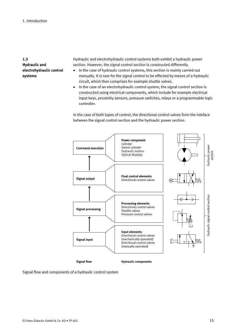
Hydraulic and electrohydraulic control systems both exhibit a hydraulic power
section. However, the signal control section is constructed differently.
• In the case of hydraulic control systems, this section is mainly carried out
manually. It is rare for the signal control to be effected by means of a hydraulic
circuit, which then comprises for example shuttle valves.
• In the case of an electrohydraulic control system, the signal control section is
constructed using electrical components, which include for example electrical
input keys, proximity sensors, pressure switches, relays or a programmable logic
controller.
In the case of both types of control, the directional control valves form the inteface
between the signal control section and the hydraulic power section.
Final control elementsDirectional control valves
Signal flow
Hyd
rau
lic
po
we
rse
ctio
nH
ydra
uli
c si
gn
al
con
tro
l se
ctio
n
Signal output
Signal processing
Signal input
Hydraulic components
Command execution
Processing elementsDirectional control valvesShuttle valvesPressure control valves
Input elementsDirectional control valves(mechanically operated)Directional control valves(manually operated)
Power componentCylinderSwivel cylinder
motorsOptical displaysHydraulic
Signal flow and components of a hydraulic control system
1.3
Hydraulic and
electrohydraulic control
systems

1. Introduction
16 © Festo Didactic GmbH & Co. KG • TP 601
Ele
ctri
cal
sig
na
l co
ntr
ol
sect
ion
Signal output
Signal processing
Signal input
Signal flow
Command execution
Hyd
rau
lic
po
we
rse
c tio
n
Electrohcomponents
ydraulic
Final contol elementsElectropneumaticallyoperated directionalcontrol valves
Processing elementsRelaysContactorsProgrammable logiccontrollers (PLCs)
Input elementsPushbuttonsControl switchesLimit switchesReed switchesInd. proximity sensorsCap. proximity switchesLight barriersPressure-actuated switches
Power componentsCylinderSwivel cylinder
motorsOptical displaysHydraulic
Signal flow and components of an electrohydraulic control system