Embed Size (px)
Citation preview

Electroencephalography (EEG)

Electroencephalography (EEG)
• Electroencephalography (EEG) is a record of electric signals
produced by synchronous action of brain cells.
Electroencephalograph system diagram [4]

EEG with Special Electrodes
• Sphenoidal Electrodes • Foramen Ovale Electrodes

EEG with Special Electrodes
• Epidural Electrodes • Subdural Electrodes

EEG with Special Electrodes
• Depth Electrodes • Nasopharyngeal
Electrodes

EEG with Special Electrodes

Scalp EEG Recording Methods
• Electrodes properties and general technical requirements
– Silver/silver chloride (Ag/AgCl), gold, tin, platinum or other metals, which do not
interact chemically with the scalp. Only high- purity metals are used.
– Low contact impedances (less than 5 k). Very low impedances of less than 100
Ω usually relate to accidental short-circuits between electrodes caused by
electrolytic gel or other conductive materials bridging the gap between sites.
– Use a fairly large contact area and using amplifiers with high input impedance
(problematic when trying to record low frequency EEG), which keeps the current
density low to reduce polarization and bias potentials (a result of the exchange of
metal ions and electrolytes in the absence of current flow) (Fisch, 1991 and
Webster 1999).
– A ground electrode should be added and connected properly
– All electrodes should be made of the same material.
– Care in storing and cleaning is necessary to prevent surface contamination.
– Electrode pastes and gels should be protected from contaminated from foreign
metal ion.
– The sensitivity of amplifiers should initially be set at 5-10µV/mm and then
adjusted as necessary.

Electrodes Positions • Electrode positions in 10-20
system. (Malmivuo and Plonsey,
1995)
• In the standard 10-20 system,
there are 19 EEG sites plus 2 ear
references.
– F, T, C, P, and O = Frontal, Temporal,
Central, Parietal and Occipital.
– Even numbers (2, 4, 6, and 8) = right
hemisphere.
– Odd numbers (1, 3, 5, and 7) = left
hemisphere.
– z = midline.
(smaller the numbers are
closer to the midline)

Electrodes Placements
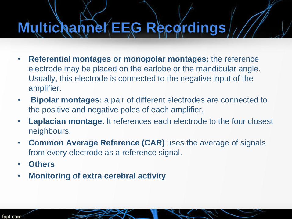
Multichannel EEG Recordings
• Referential montages or monopolar montages: the reference
electrode may be placed on the earlobe or the mandibular angle.
Usually, this electrode is connected to the negative input of the
amplifier.
• Bipolar montages: a pair of different electrodes are connected to
the positive and negative poles of each amplifier,
• Laplacian montage. It references each electrode to the four closest
neighbours.
• Common Average Reference (CAR) uses the average of signals
from every electrode as a reference signal.
• Others
• Monitoring of extra cerebral activity

Brain Anatomy [1]

Hemispheric Lateralization [1]

Sources of EEG
• The sources of EEG are the summed extracellular
synaptic potential fields generated by inhibitory and
excitatory postsynaptic activity of nerve cells in the
cerebral cortex and its underlying nuclei in response to
various kinds of input.
• The amplitude of an EEG measured with the scalp
electrodes is approximately 50 µV to 200 µV (Webster,
1999).

Neuron

Generation of Action Potential

Sources of EEG
• The action potential in the
afferent neuron causes the
release of a neurotransmitter
from its nerve terminal that
diffuses across the synaptic
cleft. This causes a local
change in the postsynaptic
potential. The potential
difference between the
postsynaptic membrane and
other parts of the neuronal
membrane causes an
electrical current to flow along
the neuronal membrane and
to change the membrane
potential of the perikaryon.

Generation of EEG (Events at a
Cholinergic Synapse)
1. An Action Potential
Arrives and Depolarizes
the Synaptic Terminal.
2. Extracellular Calcium
Ions Enter the Synaptic
Terminal, Triggering the
Exocytosis of ACh.

Generation of EEG (Events at a
Cholinergic Synapse)
3. ACh Binds to
Receptors and
Depolarizes the
Postsynaptic
Membrane.
4. ACh Is Removed
by AChE

EEGs

The Rhythmic Activity
• Alpha waves - the most prevalent normal brainwave in the EEG of a person who is
awake but relaxed.
– Frequency 8 - 12 Hz .
– Maximum amplitude over the posterior head region.
– Decrease in adult life. Disappear in drowsiness and sleep and can be blocked by eye opening.
(Berger, 1929).
• Beta waves-the normal brainwave in the EEG, which is characteristic for alertness,
focused attention, concentration or even stress and psychological tension.
– Frequency 12 - 30 Hz.
– Very low amplitude.
– Disappear in drowsiness and sleep (Berger, 1929).

The Rhythmic Activity
• Theta waves-the normal brainwave in the encephalogram of a person who is awake
but relaxed and drowsy.
– Frequency 4 - 8 Hz.
– Low amplitude.
– Children, stressed adults, during rapid-eye-movement sleep.
– The presence of theta waves under other circumstances may indicate an underlying brain
disorder (Walter and Dovey, 1944).
• Delta waves are normally seen in the EEG of a person in deep dreamless sleep or
an awake infant. It also presents during states of high conscious focused attention.
– Large amplitude (75µV to 200 µVp-p)
– Low frequency (0.5 - 4 Hz).

The Rhythmic Activity
• Gamma waves is associated with perception and consciousness (Keiser and
Lutzenberger, 2003).
– Occur as high frequency bursts with a frequency more than 35 Hz (30-100 Hz)
– Sometimes, it is included in beta waves classification (Jasper and Andrews, 1938).
• µ (mu) waves are EEG waves that show a shape suggestive of a wicket fence with
sharp tips and rounded bases.
– Frequency is generally half of the fast activity present.
– Younger adults (the central part of the head over the motor cortex)
– Can be blocked by movement, by intention to move, or by tactile stimuli.
– The EEG is not abnormal if it shows only a few trains of µ waves in one side (Sterman et al,
1974).

The Rhythmic Activity

The Rhythmic Activity
a) Normal, awake EEG; similar features
between hemispheres; and no epileptiform
activity.
b) Abnormal discharge called a generalized
spike and wave. This EEG pattern is typical
for absence seizures.
c) Abnormal discharge called focal spike. This
examples occurs over the right temporal
region of the brain.
a b
c

ERP and ERSP
• ERP (Event-related Potential) and ERSP (Event-related
Perturbation)
ERP and ERSP of the EEG
related to the real movement
transition from 0, Subject No.4,
electrode C3, CAR montage.
The time at 0 s was the
movement onset time.
ERP and ERSP of the
Independent Components
representing a typical auditory
response

Artefacts • Blinking and other eye movements. Eye movement artefacts usually
are identified by their frontal distribution, symmetry, amplitude, and their
characteristic shape.
• Muscle artefact. Muscle activity causes very brisk potentials which
usually reappear.
• Movement artefact. Movement artefacts are often erratic and not
repetitive unless the movement is rhythmical or is triggered.
• ECG. Potential changes generated by the heart are picked up in the
EEG mainly in recordings with wide inter-electrode distances, especially
in linkages across the head and to the left ear, and in subjects with
short necks. It is rarely a problem in bipolar montages.
• Pulse wave artefacts. An electrode may pick up periodic waves of
smooth or triangular shape, on or near a scalp artery due to pulse wave
producing slight changes of the electrical contact between electrode
and scalp.

Artefacts
• Perspiration artefact consists of slow waveforms that are normally
longer than 2 seconds.
• Galvanic skin response consists of slow waves, each with the period
of 0.5-1 second
• Movement of the tongue and other oropharyngeal structures may
produce irregular or repetitive slow waves in a wide distribution, often
with a maximum in the middle of the head.
• Dental restorations with dissimilar metals may produce spike-like
artefacts whenever the metal pieces are moved against each other.
• External electrical interference from the other power sources such as
power lines or electrical equipment. Normally, this form of noise is
observed as a 50 Hz or 60 Hz signal.
• Internal electrical malfunctioning
• Skin temperature difference at electrode sites can cause residual
potentials (depends on electrode’s temperature coefficient).

Deep Brain stimulation for
movement disorders

Deep Brain Stimulation • Parkinson’s Disease
Midbrain neurons project to the putamen and caudate, where
they release dopamine. When more than half of the dopaminergic
nerve terminals are affected, the motor impairments of
Parkinson’s disease arise. (resting tremor, rigidity, slowed
movement, decreased dexterity, small handwriting, flexed
posture, gait disorder, and imbalance .dementia can develop over
several years.
• Essential Tremor
begins in the arms and then spreads
to these other regions. not present
at rest.
• Dystonia

Deep Brain Stimulator System
Diagram
• Deep brain stimulation (DBS)
It is now hypothesized that DBS
increases output from the stimulated
structure, in addition to suppressing local
neuronal activity. The exact mechanism of
action remains a matter of debate (Hiner
et al., 2009). It is nondestructive,
reversible, and adjustable.

Deep Brain Stimulator
• Patient Programmer: on-off, battery
status, stimulator status, change
therapy settings (basic).
• Clinician Programmer: advance
therapy settings.
• Implantable pulse generator (IPG)
and electrodes.
• Battery: Primary cell (based on
lithium thionyl chloride (Li/SOCl2)
chemistry), lasted 3-5 yrs (bilateral
stimulation). Or, Rechargeable
secondary Li ion (9 yrs).
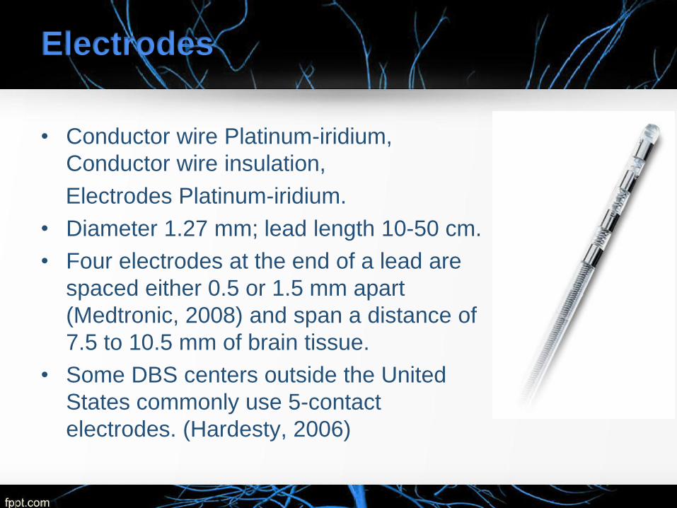
Electrodes
• Conductor wire Platinum-iridium,
Conductor wire insulation,
Electrodes Platinum-iridium.
• Diameter 1.27 mm; lead length 10-50 cm.
• Four electrodes at the end of a lead are
spaced either 0.5 or 1.5 mm apart
(Medtronic, 2008) and span a distance of
7.5 to 10.5 mm of brain tissue.
• Some DBS centers outside the United
States commonly use 5-contact
electrodes. (Hardesty, 2006)

Immunity from Electromagnetic
Interference
• must not be susceptible to electrical
influences due to external electromagnetic
fields in the range of 10 Hz-30 MHz.
• ANSI/AAMI/ISO 14708-3:2008 assess
protection from static magnetic fields,
electromagnetic fields in the range of 30-
450 MHz, and electromagnetic fields in the
range of 450 MHz3 GHz (AAMI, 2009).

Waveforms
• A rectangular waveform of adjustable duration (pulse width:
60–450 μs) and amplitude (voltage difference between anode
and cathode: 0–10.5 V). Typical settings are 2.5-3.5 V, 60-
120 μs pulse width, and 130-185 pulses/s (Medtronic, 2008).
• Reductions in tremor are typically observed only when the
frequency of stimulation is > 90Hz; conversely, low-frequency
DBS (<50Hz) often worsens symptoms [b]
• Average rate of 130 Hz was more effective at reducing tremor
when pulses were evenly spaced (Birdno et. al, 2007).
• Waveforms must be biphasic to prevent tissue damage.
• The cathodic (negative) phase of the waveform has the
greatest effect on neural activation.

Waveforms
Indication Stimulation Target Site
Dystonia Unilateral or bilateral STN or GPi
Essential Tremor Unilateral VIM
Parkinson’s Disease Bilateral STN or GPi
In vivo stimulus waveform recordings. A) Voltage-
controlled (IPG) and current-controlled stimulus
waveforms at 20 Hz and 185 Hz recorded across a 1
kΩ resistor (top) and corresponding voltage responses
recorded in vivo (bottom).
B) The peak voltage recorded in vivo was proportional
to the applied stimulus amplitude

Surgery Complications
• Death is exceedingly rare.
• Symptomatic hemorrhage, infection, and seizure each
occur in about 1% to 4% of cases.
• Complication rates increase with longer operations and
multiple electrode insertions.
• Keeping leads externalized for more during assessment
of stimulation effects increases the risk of infection.
• Repeat surgery may be necessary for subsequent
complications, such as electrode migration, skin erosion,
lead fracture, or battery failure. Batteries usually must be
replaced every 3 to 5 years.

Results
• In patients with advanced PD, bilateral stimulation of
STN or GPi over 3 months was associated with
significant improvement in motor function [a].
• Trial of 255 patients over 6 months of bilateral
stimulation showed the improvement in motor function.
However, this study demonstrated that DBS is
associated with increased risks of falls and dystonia
events (Weaver et al., 2009).
• In 21 explanted leads, recovered after 331 months from
patients, foreign body giant cells were observed (Moss et
al., 2004). Increased tissue impedance over time may
contribute to the required increase in stimulation current.

Contraindications
• Patients who will be exposed to MRI using a full body radio-
frequency (RF) coil or a head transmit coil that extends over
the chest area.
• Patients who are unable to properly operate the
neurostimulator.
• Patients for whom test stimulation is unsuccessful.
• Diathermy (e.g., shortwave diathermy, microwave diathermy or
therapeutic ultrasound diathermy), and MRI (sometimes) can
cause tissue damage resulted from heating of DBS electrodes
due to excessive energy deposition and can result in severe
injury or death (Dommerholt and Issa 2001).
• Transcranial Magnetic Stimulation (TMS).

Warnings, Precautions
• There is a potential risk of tissue damage using stimulation
parameter settings of high amplitudes and wide pulse widths.
• Extreme care should be used with lead implantation in patients with
a heightened risk of intracranial hemorrhage.
• The lead-extension connector should not be placed in the soft
tissues of the neck due to an increased incidence of lead fracture.
• Theft detectors and security screening devices may cause
stimulation to switch ON or OFF, and may cause some patients to
experience a momentary increase in perceived stimulation.
• For patients with Dystonia, age of implant is suggested to be that at
which brain growth is approximately 90% complete or above.
• Abrupt cessation of stimulation should be avoided as it may cause a
return of disease symptoms, in some cases with an greater intensity
(“rebound” effect).

Adverse Events
• Depression, suicidal ideations and suicide have been
reported, although no direct cause and effect relationship
has been established.
• Stimulation not effective, cognitive disorders, pain,
dyskinesia, dystonia, speech disorders including
dysarthria, infection, paresthesia, intracranial
hemorrhage, electromagnetic interference,
cardiovascular events, visual disturbances, sensory
disturbances, device migration, paresis/asthenia,
abnormal gait, incoordination, headaches, lead
repositioning, thinking abnormal, device explant,
hemiplegia, lead fracture, seizures, respiratory events,
and shocking or jolting stimulation.

Target Localization 1. The patient’s head is fit with a rigid frame that provides a three-
dimensional coordinate system for target localization. The patient’s
brain is imaged using magnetic resonance imaging (MRI).
2. After the brain is exposed, a platinum-iridium alloy, insulated with
glass, microelectrode recording (MER) is advanced from the
cortical surface to the target. As the electrode tip passes, voltage
characteristics of the signal enable structures to be identified.

Target Localization
3. Associated movement, is used to fine-tune the microelectrode
location. The clinician listens for the modulation of action
potential discharge in relation to passive movements of
opposite side limbs. (Sillay & Starr, 2009).

Programming
4. The leads are then secured in a
lead anchoring device on the
skull, before the pulse generator
is implanted several weeks later.
Many programmers wait 2 to 4
weeks to allow for resorption of
edema near the lead. Settings
are programmed on a handheld
computer that communicates to
the IPG via a magnetic interface.

References
1. Fundamental of Anatomy and Physiology, Frederic H.
Martini
2. Biomedical Instrumentation: Application and Design, John G.
Webster
3. Introduction to Medical Electronics Applications, D. Jennings
4. Medical Device Technologies: A Systems Based Overview
Using Engineering Standards, Gail D. Baura
5. Bioimpedance and Bioelectricity Basics, Orjan G. Martinsen
6. The Biomedical Engineering Handbook, Joseph D. Bronzino
7. www.medtronic.com