Embed Size (px)
Citation preview
APPROVED: Teresa D. Golden, Major Professor William E. Acree, Jr., Committee Member and
Chair of the Department of Chemistry Michael Monticino, Dean of the Robert B.
Toulouse School of Graduate Studies
ELECTROCHEMICAL DEPOSITON OF ZINC-NICKEL ALLOYS IN ALKALINE
SOLUTION FOR INCREASED CORROSION RESISTANCE
Heidi A. Conrad
Thesis Prepared for the Degree of
MASTER OF SCIENCE
UNIVERSITY OF NORTH TEXAS
December 2009

Conrad, Heidi A. Electrochemical deposition of zinc-nickel alloys in alkaline
solution for increased corrosion resistance.
The optimal conditions for deposition of zinc-nickel alloys onto stainless steel
discs in alkaline solutions have been examined. In the past cadmium has been used
because it shows good corrosion protection, but other methods are being examined due to
the high toxicity and environmental threats posed by its use. Zinc has been found to
provide good corrosion resistance, but the corrosion resistance is greatly increased when
alloyed with nickel. The concentration of nickel in the deposit has long been a debated
issue, but for basic solutions a nickel concentration of 8-15% appears optimal. However,
deposition of zinc-nickel alloys from acidic solutions has average nickel concentrations
of 12-15%. Alkaline conditions give a more uniform deposition layer, or better metal
distribution, thereby a better corrosion resistance. Although TEA (triethanolamine) is
most commonly used to complex the metals in solution, in this work I examined TEA
along with other complexing agents. Although alkaline solutions have been examined,
most research has been done in pH ≥ 12 solutions. However, there has been some work
performed in the pH 9.3-9.5 range. This work examines different ligands in a pH 9.3-9.4
range. Direct potential plating and pulse potential plating methods are examined for
optimal platings. The deposits were examined and characterized by XRD.
Master of Science (Chemistry), December
2009, 128 pp, 5 tables, 77 illustrations, references, 36 titles.

ii
Copyright 2009
by
Heidi A. Conrad

ACKNOWLEDGEMENTS
I would like to thank my research advisor, Dr. Teresa D. Golden for her continued
support, guidance and encouragement while working on this research project.
I would like to thank Dr. William E. Acree for taking time to be a part of my
committee, and his guidance in completing my research and thesis.
I would like to give a special thank you to Dr. Jose Calderon for all of his help
with the use of different instruments needed to complete my research.
I would like to give a special thank you to John R. Corbett, who worked for me as
a TAMS (Texas Academy of Math and Science) student. John was a great help in the lab
running experiments and giving suggestions as needed.
I would like to thank all of my group members for their great advice and ideas in
completing my research.
I would also like to thank my daughter Samantha for being so patient as I try to
finish school, and being so helpful when needed and to my mom, Gayle, for being there
and believing in me, I really appreciate all you do for me.
iii

TABLE OF CONTENTS
ACKNOWLEDGEMENTS………………………………………………………………iii
LIST OF TABLES…………………………………………………………..………….viii
LIST OF ILLUSTRATIONS……………………………………………………………..ix
CHAPTER 1. INTRODUCTION AND LITERATURE REVIEW………………….…...1
1.1Electrodeposition of Alloys and Applications…………………………………1
1.2 Zinc Alloys…………………………………………………………………….2
1.2.1 Alloy Phases of Zinc-Nickel………………………………………...4
1.2.2 Temperature Dependence of Alloys………………………………...5
1.2.3 Nickel Content………………………………………………………6
1.3 Acid Bath Deposition………………………………………………………….6
1.3.1 Current Density and Effect of Deposition Potential in Acidic
Conditions…………………………………………………………………6
1.3.2 Pulse Plated Nickel in Acidic Conditions…………………………...9
1.3.3 Cyclic Voltammetric Study of Zinc Nickel Alloy Deposition in
Acidic Conditions………………………………………………………..11
1.3.4 Acidic Deposition Conditions……………………………………...15
1.3.5 X-Ray Diffraction Data for Acidic Depositions…………………...18
1.3.6 Acidic Deposition Mechanism……………………………………..20
1.3.7 Initial Deposition Studies for Acidic Conditions…………………..22
1.3.8 Effects of Morphology for Acidic Deposits………………………..26
1.3.9 Acid Deposition Conclusions……………………………………...27
iv

1.4 Alkaline Bath Deposition…………………………………………………….28
1.4.1 Hydrogen Embrittlement of Deposits……………………………...29
1.4.2 Electrolytic Properties of the Alkaline Baths………………………30
1.4.3 Complexing Agents for Alkaline Baths…………………………....34
1.5 Corrosion Protection from Alkaline Deposits………………………………..35
1.5.1 Salt Spray Testing………………………………………………….37
1.5.2 Sacrificial Electrodes………………………………………………39
1.5.3 Corrosion Phase………………………………………………….39
1.6 Summary……………………………………………………………………..40
1.6.1 This Thesis Work…………………………………………………..41
CHAPTER 2. DEPOSITION OF PURE METAL FILMS IN ALKALINE
SOLUTIONS…………………………………………………………………………….43
2.1 Introduction…………………………………………………………………..43
2.2 Experimental Parameters…………………………………………………….45
2.3 Zinc Sources for Deposition…………………………………………………48
2.3.1 Zinc Nitrate………………………………………………………...51
2.3.1.1 Zinc Nitrate Conclusions………………………………………………………...54
2.3.2 Zinc Sulfate Monohydrate…………………………………………54
2.3.2.1 Zinc Monosulfate Monohydrate
Conclusions………………………………………………..…......60
2.4 Borate Solutions for Zinc…………………………………………….………60
2.4.1 Zinc Sulfate Monohydrate in Borate……………………………….61
v

2.4.1.1 Zinc Sulfate Monohydrate conclusions for borate solutions…….62
2.5 Nickel Sources for Deposition……………………………………………….63
2.5.1 Nickel Sulfate Hexahydrate………………………………………..64
2.5.1.1 Nickel Sulfate Hexahydrate conclusions………………………...70
2.5.2 Nickel Ammonium Sulfate Hexahydrate…………………………………………..71
2.5.2.1 Nickel Ammonium Sulfate Hexahydrate Conclusions……………….………….77
2.6 Borate Solutions for Nickel………………………………………………….77
2.6.1 Nickel Sulfate Hexahydrate in Borate……………………………..78
2.6.1.1 Nickel Sulfate Hexahydrate in borate Conclusions……………………………...79
2.6.2 Nickel Ammonium Sulfate Hexahydrate in Borate………………..80
2.6.2.1 Nickel Ammonium Sulfate Hexahydrate in Borate Conclusions………………..81
2.7 Nickel and Zinc Conclusions………………………………………………...81
2.8 Bath Conditions……………………………………………………………...82
2.9 Summary……………………………………………………………………..83
CHAPTER 3. ZINC AND NICKEL CO-DEPOSITION IN ALKALINE
SOLUTIONS…………………………………………………………………………….85
3.1 Introduction…………………………………………………………………..85
3.2 Initial Studies………………………………………………………………...87
3.3 Chronocoulometry…………………………………………………………...97
3.4 Linear Sweep Voltammetry…………………………………………..……...99
3.5 Atomic Absorption Analysis………………………………………………..101
3.6 Alkaline Metal Deposition from Water Solvent with Acetate Ligand……..101
vi

vii
3.6.1 Zinc Sulfate Monohydrate and Nickel Sulfate Hexahydrate……..102
3.6.1.1 Zinc-Nickel 1:1 Molar Ratio……………………………102
3.6.1.2 Zinc-Nickel 3:1 and 4:1 Molar Ratios………………….104
3.6.2 Zinc Sulfate Monohydrate and Nickel Ammonium Sulfate
Hexahydrate…………………………………………………………….109
3.6.2.1 Zinc-Nickel 2:1 Molar Ratio……………………………110
3.6.2.2 Zinc-Nickel 1:2 Molar Ratio……………………………111
3.6.3 Conclusions for Alkaline Metal Deposition from Water Solvent with
Acetate Ligand………………………………………………………….113
3.7 Alkaline Metal Deposition from Borate Solvent…………………………...113
3.7.1 Zinc Sulfate Monohydrate and Nickel Sulfate Hexahydrate……..114
3.7.1.1 Zinc Nickel in a 1:1 Molar Ratio……………………….114
3.7.1.2 Zinc and Nickel in a 1:3 Molar Ratio…………………..116
3.7.2 Zinc Sulfate Monohydrate and Nickel Ammonium Sulfate Hexahydrate in
Borate………………………………………………….117
3.7.2.1 Zinc-Nickel 1:1 Molar Ratio……………………………117
3.7.2.2 Zinc Nickel 2:1 Molar Ratio……………………………118
3.7.3 Conclusions for Alkaline Metal Deposition from Borate Solvent..120
3.8 Conclusions for Zinc-Nickel Co-Deposition in Alkaline Solutions………..120
3.9 Differences from Literature………………………………………………...123
3.10 Future Work……………………………………………………………….124
REFERENCES………………………………………………………………………...126

LIST OF TABLES
Table 2.1: Possible ligands for zinc; zinc complex pKa’s…………….…………………48
Table 2.2: The powder diffraction file (PDF) data of XRD patterns of standard zinc metal
from the JCPDS Database (PDF #04-0831)……………………………………………..50
Table 2.3: The PDF data of XRD patterns of standard nickel metal from the JCPDS
Database (PDF#04-0850)………………………………………………………………...64
Table 2.4: Possible ligands for nickel; nickel complex pKa values……………………..65
Table 3.1: The PDF data of XRD patterns of standard zin-nickel alloy, gamma phase
metal from the JCPDS Database (PDF #06-0653)………………………………………86
viii

LIST OF ILLUSTRATIONS
Figure 1.1: Potential compared to hydrogen electrode…………………………………....3
Figure 1.2 Deposition ranges in acidic solutions………………………………………….7
Figure 1.3: E-I curve. Deposition of Zn, Ni and Zn-Ni alloys……………………………8
Figure 1.4: Cyclic voltammagram study of nickel deposition onto a glassy carbon
substrate………………………………………………………………………………….12
Figure 1.5: CVs of nickel deposition onto platinum and glassy carbon substrates……...13
Figure 1.6: CVs of Zn-Ni deposition from chloride plating solution……………………14
Figure 1.7: CV of Zn, Ni and Zn-Ni alloy on steel………………………………………16
Figure 1.8: Deposition of nickel, zinc and Zn-Ni alloy on steel………..………………..17
Figure 1.9: XRD pattern from 30.0°C bath, predominately δ phase…………………….19
Figure 1.10: XRD pattern from 50.0°C bath, predominately γ phase…………………...19
Figure 1.11: Analysis of zinc-nickel alloy deposit……….……………………………...23
Figure 1.12: Depth profiling of zinc-nickel coating, hydrogen in the deposit……….…..24
Figure 1.13: Model of deposit layer……………………………………………………...25
Figure 1.14: Pourbaix diagram of zinc species…….……………………………………32
Figure 1.15: Pourbaix diagram of nickel species……...…………………………………33
Figure 1.16: Salt spray testing of zinc-nickel coating on steel substrate……..………….36
Figure 1.17: Salt spray corrosion tests…………...………………………………………37
Figure 1.18: Salt spray corrosion resistance tests – chromated samples…………….…..38
Figure 2.1: Potential step method diagram…..…………………………………………..44
ix

Figure 2.2: Set up of electrochemical cell…………..…………………………………...45
Figure 2.3: Stainless steel disc background mounted in epoxy…...……………………..46
Figure 2.4: Stainless steel background disc, out of epoxy……………………………….47
Figure 2.5 Structure of zinc ammonia complex……………………...…………………..49
Figure 2.6 Structure of zinc tartaric acid\complex………....…………………………….49
Figure 2.7 Structure of zinc acetate complex……...……………………………………..49
Figure 2.8 Structure of zinc triethanolamine complex…...………………………………50
Figure 2.9 Zinc nitrate…………………………………………………………………....51
Figure 2.10: CV of zinc nitrate, pH=9.3 with 1M NH4OH………………………….…..52
Figure 2.11: CV of zinc nitrate, tartaric acid, and pH=9.3 with 1M NH4OH……………53
Figure 2.12 Zinc sulfate monohydrate…………….……………………………………..54
Figure 2.13: CV of zinc sulfate monohydrate, triethanolamine with pH=9.3 with 1M
NH4OH…………………………………………………………………………………...55
Figure 2.14: XRD Pattern of zinc sulfate monohydrate, triethanolamine, and pH=9.3 with
1M NH4OH………………………………………………………………………………56
Figure 2.15: CV of zinc sulfate monohydrate and triethanolamine, pH=11.04 with 1.5M
NH4OH…………………………………………………………………………………...57
Figure 2.16: CV of zinc sulfate monohydrate and sodium acetate, pH=9.3 with 1M
NH4OH…………………………………………………………………………………...58
Figure 2.17: XRD Pattern of zinc sulfate monohydrate with sodium acetate, pH=9.32
with 1M NH4OH…………………………………………………………………………59
Figure 2.18: CV of 0.5M Zn in 0.1M borate, pH=9.3 with 1M NH4OH………………...61
x

Figure 2.19: XRD pattern of zinc deposited from 0.1M borate solution, pH=9.3 with 1M
NH4OH……………………………………………………………...……………………62
Figure 2.20: Nickel sulfate hexahydrate structure………………..……………………...64
Figure 2.21 Nickel ammonia……………..………………………………………………65
Figure 2.22 Nickel acetate .……….……………………………………………………..66
Figure 2.23 Nickel triethanolamine ….……………………….…………………………66
Figure 2.24: CV of nickel sulfate hexahydrate, sodium acetate, and pH=9.32 with 1M
NH4OH…………………………………………………………………………………...68
Figure 2.25: XRD pattern of nickel sulfate hexahydrate, sodium acetate, and pH=9.32
with 1M NH4OH…………………………………………………………………………70
Figure 2.26: Nickel ammonium sulfate structure……..…………………………………71
Figure 2.27: CV of nickel ammonium sulfate hexahydrate, pH=9.3 with 1M
NH4OH…………………………………………………………………………………...73
Figure 2.28: CV of nickel ammonium sulfate hexahydrate, pH=9.3 with 1 M
NH4OH………………………………………………………………………...…………74
Figure 2.29: XRD pattern of nickel ammonium sulfate hexahydrate and 1M NH4OH, not
in epoxy and plated at E=-1.50V…………………………..…………………………….75
Figure 2.30: XRD pattern of nickel ammonium sulfate hexahydrate, pH=9.3 with 1M
NH4OH, not in epoxy, plated at E=-1.250V……………………………………………..76
Figure 2.31: CV of nickel in borate solution, pH=9.3 with 1M NH4OH………………...78
Figure 2.32: XRD pattern of nickel sulfate hexahydrate in 0.1M borate solution, pH=9.3
with 1M NH4OH…………………………………………………………………………79
xi
Figure 2.33: XRD pattern of nickel ammonium sulfate hexahydrate in 0.1M borate
solution, pH=9.3 with 1M NH4OH………………………………………………………81
Figure 3.1 XRD pattern gamma phase alloy…………...………………………………...87
Figure 3.2: CV of 0.5M ZnSO4.H2O, 0.5M NiSO4
.6H2O and 1.0M acetate in solution,
pH=9.3 with 1M NH4OH………………………………………………………………...88
Figure 3.3: CV of 0.5M ZnSO4.H2O, 0.5M NiSO4
.6H2O, 1.0M Na+CH3COO-, pH=9.32
with 1M NH4OH…………………………………………………………………………90
Figure 3.4: CV of 0.5M ZnSO4.H2O, 0.5M NiSO4
.6H2O, 0.25M Na+CH3COO-, pH=9.34
with 1M NH4OH…………………………………………………………………………91
Figure 3.5: XRD pattern of plating from 0.5M ZnSO4.H2O, 0.5M NiSO4
.6H2O, 0.25M
Na+CH3COO-, pH=9.34 with 1M NH4OH ……………………………………...............92
Figure 3.6: XRD pattern from 0.5M ZnSO4.H2O, 0.25M NiSO4
.6H2O, 0.25M
Na+CH3COO-, pH=9.3 with 1M NH4OH………………………..………………………93
Figure 3.7: CV of 0.5M ZnSO4.H2O, 0.5M NiSO4
.6H2O, 0.5M Na+CH3COO-, pH=9.32
with 1M NH4OH…………………………………………………..……………………..94
Figure 3.8: CV of 0.5M ZnSO4.H2O, 0.5M Ni(NH4)2(SO4)2
.6H2O, 0.5M Na+CH3COO-,
pH=9.3 with 1M NH4OH…………………………...……………………………………95
Figure 3.9: XRD pattern from solution of 0.5M ZnSO4.H2O, 0.5M
Ni(NH4)2(SO4)2.6H2O, 0.5M Na+CH3COO-, pH=9.3 with 1M NH4OH……….………...96
Figure 3.10: Chronoucoulometry diagram………..………………………….…………..97
Figure 3.11 Anson plot diagram………………….……………………………………...98
Figure 3.12 LSV of zinc, nickel and zinc-nickel alloy…………………………………100
xii

Figure 3.13: CV of 1:1 ratio of zinc-nickel, with acetate, pH=9.39 with 1M
NH4OH………………………………………………………………………………….103
Figure 3.14: XRD Pattern, 1:1 Zn-Ni ratio with acetate ligand, pH=9.3 with 1M
NH4OH………………………………………………………………………………….104
Figure 3.15- 3:1 Molar ratio of ZnSO4.H2O, NiSO4
.H2O, pH=9.37 with 1M
NH4OH….........................................................................................................................105
Figure 3.16- XRD pattern of gamma phase alloy deposited from 2:1 ZnSO4.H2O,
Ni(NH4)2(SO4)2.6H2O………...………………………………………………………...106
Figure 3.17: AAS standard addition method- zinc concentration determination……....107
Figure 3.18: AAS standard addition method- nickel concentration determination…….107
Figure 3.19 XRD pattern 4:1 ratio zinc to nickel……………………...………………..109
Figure 3.20: XRD pattern, 1:1 Zn-Ni ratio with acetate ligand, pH=9.3 with 1M
NH4OH………………………………………………………………………………….110
Figure 3.21: XRD Pattern, 1:1 Zn-Ni ratio with acetate ligand, pH=9.3 with 1M
NH4OH………………………………………………………………………………….112
Figure 3.22 CV of 0.1M ZnSO4.H2O, 0.1M NiSO4
.6H2O, 0.1M borate and a pH of 9.41
with 1M NH4OH………………………………………………………………………..114
Figure 3.23: XRD pattern, 1:1 Zn-Ni ratio in 0.1M borate, pH=9.41 with 1M
NH4OH………………………………………………………………………………….115
Figure 3.24: XRD pattern, 1:3 Zn-Ni ratio in 0.1M borate, pH=9.41 with 1M
NH4OH………………………………………………………………………………….116
Figure 3.25: XRD pattern, 1:1 Zn-Ni ratio with acetate ligand, pH=9.3 with 1M
NH4OH………………………………………………………………………………….118
xiii

xiv
Figure 3.26: XRD Pattern, 1:1 Zn-Ni ratio with acetate ligand, pH=9.3 with 1M
NH4OH………………………………………………………………………………….119

CHAPTER 1
INTRODUCTION AND LITERATURE REVIEW
1.1 Electrodeposition of Alloys and Applications
There is great interest in the electrodeposition of metallic alloys because of the
increase in mechanical and chemical properties of the metals involved. For example, the
mechanical properties of zinc are greatly increased when alloyed with nickel [1]. Zinc
alloys are of great interest in research because they offer a greater resistance to corrosion
then pure zinc [2]. Thus modifying the composition can significantly improve the
stability of the metal system against corrosion [3].
Due to the automotive industry, there has been a real push to improve the
corrosion resistance of stainless steel. To date, cadmium and zinc coatings have been
used for the corrosion protection of steel. Although these materials do protect the
underlying steel, the protection offered needs to be increased. There are some high
corrosion resistant materials, but they tend to be very costly and not widely available [4].
For many years zinc coated stainless steel has been used in this field as a
corrosive resistive material. The zinc coating sacrificially decays on the stainless steel,
thereby protecting it [4]. Other options are being examined to withstand harsher
conditions, longer life of resistance, and reducing the coating thickness required for a
specific resistance time frame.
Electrodeposited zinc-nickel alloys have been examined for increased corrosion
resistance in the automotive industry. The automotive industry needs to find some type
of coating that can withstand the high salt conditions automobiles are exposed to during
1

icy road conditions. There is also the need to find a replacement for cadmium coatings
due to the high toxicity of working with cadmium [5]. Historically cadmium has been
deposited out of a cyanide bath, the use of cyanide is becoming more regulated, as is the
use of cadmium, since cadmium metal and cyanide salts are toxic [6].
At this point, alloys are being examined as a solution to this problem. Alloys
have different corrosion potentials then their single elements; therefore by picking the
correct combination of alloys, one can greatly increase the corrosion resistance of the
material [4].
1.2 Zinc Alloys
As a result of the push for increased corrosion resistance, the study of alloying
zinc with other metals began [5]. Cadmium was another metal often used in the
corrosion protection of steel, because, like zinc, it corrodes preferentially to the steel,
thereby protecting the steel [4]. Traditionally, zinc was alloyed with cadmium, but due to
the harsh environmental conditions associated with cadmium, other metals have been
examined [5]. Cadmium has become very regulated, or in some countries banned all
together, and zinc-nickel is a cheap environmentally friendlier alternative.
The biggest advantage for zinc-nickel deposits is that they can replace cadmium
plating in most applications [4]. Alloys that are high in zinc content retain cathodic
potential to steel [7]. The alloys are more electrochemically noble than pure zinc, so
sacrificial protection to the steel substrate is maintained but they still corrode at a slower
rate. Zinc-nickel alloys have a cathodic potential compared to steel, which is controlled
by the nickel content in the deposit [4], as can be seen in Figure 1.1.
2

Figure 1.1: Potential compared to hydrogen electrode [7].
For zinc, if the alloy is especially high in zinc content it still presents cathodic
potential to steel, thereby being preferentially corroded. However, the alloy corrodes at a
much slower rate than pure zinc because the alloy is less active then pure zinc. Some
zinc alloys that have been examined include zinc-cobalt, zinc-iron and zinc-nickel. The
work has mainly focused on zinc-nickel because this alloy has the highest documented
corrosion resistance. As the nickel content increases, the corrosion potential increases
which is due to microcracking. Microcracking spreads out the corrosion cells being
formed on the deposit so that there are many weak cells but few strong cells which leads
to a prolonged life of the coating. The corrosion cells are what enable the corrosives to
burrow down to basis metal, causing red rust. White rust is due to corrosion of the zinc
alloy deposit and red rust is due to the corrosion of the underlying stainless steel substrate
[8]. When a corrosion cell forms on the surface of a pure zinc coating, it forms and
3

quickly digs in through the zinc coating to the underlying steel substrate. When alloyed
with nickel, the corrosion cell is blocked by nickel and cannot quickly burrow through
the zinc coating. Instead, due to the microcracking, many small corrosion cells are
formed on the surface of the alloy coating, eventually leading on to full corrosion, but
increasing the time frame for the corrosion of the underlying steel to begin [4].
Zinc alloy deposits on a microscopic level, are more granular in texture and
generally harder than cadmium or pure zinc coatings. The oxidation of zinc is slowed
down by the nickel in the deposit, as oxidation progresses, the nickel remains as a barrier
against further corrosion. Therefore, initially the corrosion protection is sacrificial, but as
the corrosion continues, a gradual switch to barrier protection is observed [8].
Zinc has a low standard electrode potential (E=-0.76V vs. SHE) and is a very
active metal that corrodes easily. This allows zinc to act as a suitable sacrificial coating
on many metals with higher standard electrode potentials. The driving force for the
corrosion of the zinc in corrosive environments is the difference in electronegativity of
the coating and the substrate. When alloyed with another metal, the potential of the alloy
can be brought much closer to that of the substrate metal, while still being on the cathodic
side, thereby acting as a good sacrificial coating [9].
1.2.1 Alloy Phases of Zinc-Nickel
The five zinc-nickel alloy phases that have been detected are the following: η- (1%
Ni), α and β (30% Ni, known as the nickel rich phases), and [10] and - γ (Ni5Zn21) and δ-
(Ni3Zn22) (known as the zinc rich phases) phases dependent upon the Zn/Ni ratio used [3,
10, 11]. The γ and δ phases are most commonly found in the alkaline bath deposits,
4

with the γ phase showing the strongest protection against corrosion. Nickel is able to
enhance the corrosive resistance properties of zinc. There are many techniques utilized
for this deposition, the most common being the use of a rotating disk electrode. The α
and β phases are known as the nickel rich phases having a nickel content around 30%.
The η phase has about 1% nickel content but is only found when electrodeposited in a
chloride bath. The γ and δ phase alloys would be the best at corrosion resistance since
the alloys with a nickel content of approximately 8-15% have been found to be optimal.
The phase of the alloy present is temperature dependent, so to obtain the γ phase alloy,
which has been determined to be the best resistance to corrosion, a higher temperature is
needed in acidic conditions. 50.0°C is predominately γ phase, making this the optimal
temperature at which to deposit the coating from acidic bath conditions [3].
1.2.2 Temperature Dependence of Alloys
There is also a need for increased corrosion resistance under different temperature
conditions, such as under the hood of a car. In such “hot zone” conditions, zinc alone
does not perform well and chromate has no effect at these temperatures. Zinc also
produces white oxide products. The production of these bi-products becomes an issue
when trying to dismantle and reassemble parts during their service life. Increased deposit
hardness is also being examined to extend the life of corrosive components of vehicles
[7].
5
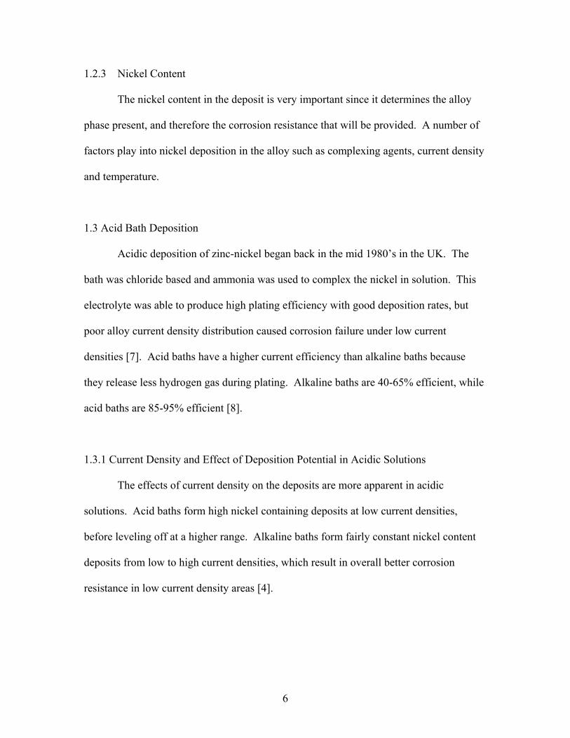
1.2.3 Nickel Content
The nickel content in the deposit is very important since it determines the alloy
phase present, and therefore the corrosion resistance that will be provided. A number of
factors play into nickel deposition in the alloy such as complexing agents, current density
and temperature.
1.3 Acid Bath Deposition
Acidic deposition of zinc-nickel began back in the mid 1980’s in the UK. The
bath was chloride based and ammonia was used to complex the nickel in solution. This
electrolyte was able to produce high plating efficiency with good deposition rates, but
poor alloy current density distribution caused corrosion failure under low current
densities [7]. Acid baths have a higher current efficiency than alkaline baths because
they release less hydrogen gas during plating. Alkaline baths are 40-65% efficient, while
acid baths are 85-95% efficient [8].
1.3.1 Current Density and Effect of Deposition Potential in Acidic Solutions
The effects of current density on the deposits are more apparent in acidic
solutions. Acid baths form high nickel containing deposits at low current densities,
before leveling off at a higher range. Alkaline baths form fairly constant nickel content
deposits from low to high current densities, which result in overall better corrosion
resistance in low current density areas [4].
6

Figure 1.2: Deposition ranges in acidic solutions [12].
There are 3 ranges of deposition in acidic solutions as shown in Figure 1.2. The
first range containing small potentials (-0.700 to -0.800V) gives coatings containing ≥95
wt % Ni. In the second range, where there are intermediate potentials, the alloys are
approximately 75 wt% Ni and the cathodic current efficiency drops. The third range
includes high potentials (-1.04 to -1.02V) and the Ni quantity decreases from 45 to 15 wt.
%, but the potential increases and the γ-phase Zn/Ni alloy predominates [12]. At low
current densities, the alloy is almost pure nickel in content without the electrochemical
characteristics of nickel. When the zinc content in the deposit reaches 10%, the current
efficiency of the system begins to decrease. As the current efficiency drops, the zinc
greatly inhibits the deposition of nickel in the deposit, while the presence of nickel aids in
the deposition of zinc. As the potential is shifted more negatively, alpha phase deposition
is observed with high hydrogen evolution. As the potential is shifted even more in the
negative direction, gamma phase deposition is observed, with a sharp decrease in the
7

hydrogen evolution [11]. Low current densities can lead to normal deposition, where the
nickel deposits preferentially to the zinc. For improved corrosion resistance, anomalous
deposition must occur, with the zinc preferentially depositing to the nickel [3].
Figure 1.3 shows a study performed by Abou-Krisha where it is noted that the
deposition of zinc starts around E=-1.14V, and had a similar shape to the potential of Zn-
Ni codeposition (which occurs around E=-1.12V) [1].
Figure 1.3: E-I curve. Deposition of Zn, Ni and Zn-Ni alloys [1].
It was also observed that Ni deposition began around E=-0.85V and as the
potential was shifted to more negative values, the growth of the deposited layer greatly
increased. The polarization curve of the alloy is between those of Ni or Zn only,
suggesting the codeposition allows the Zn to deposit at a more positive potential and the
Ni to deposit at more negative potential, due to presence of Ni2+ which aids in Zn
8

deposition [1] so zinc can co-deposit with nickel at potentials that are too low for it to
deposit in pure form [13].
As Ni2+ concentration increases, the deposit potential positively increases. The
cathodic peak current initially starting at -0.5V (believed to be due to hydrogen
evolution) decreases as Ni2+ concentration is increased. The amounts of γ-phase and δ-
phase alloys are dependent upon the concentration of Ni2+ in solution. A higher
concentration of Ni2+ leads to a higher content of γ-phase which is zinc rich [1, 14].
Anomalous deposition occurs in the zinc overpotential deposition region. Above
potentials of -1.0V vs. Ag/AgCl alloy deposition is inhibited in relation to pure nickel,
but is more readily deposited compared to pure zinc [13]. As current density is increased,
a higher overpotential is required to create nucleation sites on the electrode and to deposit
zinc, but the deposit can still grow at lower potentials [11].
1.3.2 Pulse Plated Nickel in Acidic Conditions
There is a correlation between crystal orientation and the corrosion potential
during anodic polarization. There have also been many studies performed on the growth
of nickel crystals on different substrates.
Under acidic conditions, the deposition of nickel follows a number of
intermediate steps as indicated:
Ni2+ + H2O ↔ NiOH+ + H+ (Equation 1.1)
NiOH+ + e- → NiOHad (Equation 1.2)
NiOHad + H+ + e- ↔ Ni0 + H2O (Equation 1.3)
9

When a pulsed current plating method is employed, with short cathodic pulses (1
ms or less) and high current densities (16A/dm2 or greater) another mechanism is
followed. There is a considerable pH increase near the cathode surface during a pulse, so
a layer of colloidal nickel hydroxide is formed at this surface. Micelles then form by
attaching further nickel ions.
Ni2+ + 2OH- → [Ni(OH)2]colloidal (Equation 1.4)
{Ni2+[Ni(OH)2]} colloidal (Equation 1.5)
Nickel deposition from this second mechanism is semibright in appearance and
has a different texture then direct current plated nickel. With the use of pulse plating, one
can improve the overall material distribution while obtaining more resistant coatings [16].
During the pulse deposit, the shortest on-time results in a deposit surface that is smooth
with no apparent cavities. The longer the on-time, the greater number of cavities present
on the deposit surface. In nickel pulse plating, as you increase the pause to pulse ratio,
the nickel content in the alloy is decreased. The time it is pulsed to a higher potential has
little effect on the alloy composition [15]. The cavities are a result of hydrogen gas
bubbles that can linger on the cathode surface during deposition. The density of the
hydrogen gas bubbles at the cathode surface increases as the on-time is increased, which
represents a higher overpotential for the nickel deposition. The morphology present on
the deposits of the shortest on-time results in large pyramidal-shaped crystallites with
preferential growth exhibited [17]. Direct current plating produces coatings with a higher
amount of surface roughness than when obtained with a pulse plating [18].
10

In acidic conditions, the corrosion rate of the 220 crystallites, which is the
preferred orientation obtained from direct current plating, is commonly higher than the
corrosion rate of the 200 crystallites, which is the preferred orientation obtained from
pulse platings [16].
Pulse plating disturbs the adsorption-desorption processes on the electrode
surface, which in turn controls the microstructure of the deposit [17]. Pulse plating leads
to a better metal distribution present in the deposit [16].
1:3.3 Cyclic Voltammetric Study of Zinc Nickel Alloy Deposition in Acidic Conditions
Lin and Selman performed an extensive cyclic voltammetry (CV) study to
determine the phase formation of the zinc-nickel alloy [19].
First, a typical CV of a nickel chloride salt solution was examined with a working
electrode of glassy carbon (GC) (the solid line present in figure 1.5). It is observed that
with a GC substrate, the deposition occurs at a cathodic potential of -0.88V. This is
almost 500mV past the normal equilibrium potential of nickel which is -0.496V vs. SCE.
This is indicative of overcoming an energy barrier present from deposition onto a foreign
substrate. In the potential range of -1.1 to -0.88V, the anodic sweep is more cathodic
then during the cathodic sweep of the potential. This is caused by two factors. First,
nickel nucleation is occurring on the substrate and second, the substrate effect on the rate
of hydrogen evolution. Once the cathodic direction sweep is complete, nickel deposits
have covered the substrate surface, so hydrogen evolution occurs more readily then on
the pure substrate [19].
11

Figure 1.4: Cyclic voltammogram study of nickel deposition onto a glassy carbon
substrate [19].
It is clear that with convection in figure 1.4, the deposition potential shifts in a
negative direction (approximately E= -0.91V), compared to the CV without convection.
It was found that nickel that was deposited in the α phase dissolves around a
potential of -0.1V during a potential-sweep stripping method. β-phase nickel dissolves
around E=-0.2V and pure nickel dissolves around E= + 0.1V. The α phase nickel is
composed of a solid mixture of hydrogen atoms in nickel, in an H/Ni ratio of 0.03. The β
phase nickel is composed of interstitial hydrogen atoms with the nickel, in an H/Ni ratio
12

greater than 0.6. It is believed that the anodic current present in figure 1.4 is due to the
dissolution of nickel from the hydrogen-nickel solid solution and the hydrogen evolution
from the substrate surface. It was concluded that the deposit of nickel onto a glassy
carbon substrate was a combination of nickel and hydrogen [19].
Figure 1.5: CVs of nickel deposition onto platinum and glassy carbon substrates [19].
Figure 1.5, CVs of nickel deposition onto platinum and glassy carbon substrates;
clearly demonstrate the substrate effect on nickel deposition onto a platinum electrode.
Hydrogen evolution begins to appear at a potential of -0.386V on the platinum electrode
during the cathodic-sweep direction. During the anodic-sweep direction, the current is
below that seen during the cathodic-direction sweep, due to less of the platinum surface
being exposed for hydrogen evolution to occur [19].
13

It is determined from figure 1.5 that hydrogen and nickel are codeposited.
Hydrogen evolution is rapid at the platinum surface, so a cathodic current appears at a
potential of -0.39V. The cathodic potential is -0.81V which is same potential when
deposited onto glassy carbon that the nickel deposition rate increases sharply [19].
Figure 1.6: CVs of Zn-Ni deposition from chloride plating solution [19].
Figure 1.6, CVs of Zn-Ni alloy deposition from a chloride based solution, shows
CVs with and without convection of Zn-Ni depositions. Near E= +0.160V, a mass-
transfer limitation of hydrogen adsorption is observed in the cathodic-direction sweep.
The sharp increase near E= -0.38V is due to hydrogen evolution [19].
This study was able to determine that hydrogen evolution does play a key role in
the electrodeposition of Zn-Ni alloys and depending on the strength of the adsorption of
hydrogen atoms on the surface of the substrate, 3 different types of nickel solid can be
formed. After the initial deposit of nickel onto the substrate, the hydrogen evolution is
14

enhanced, thereby lowering the current efficiency of the system during the electroplating
of the zinc-nickel alloy. As expected, when alloyed, the electrochemical properties of the
metals in the alloy are changed, and for zinc, the deposition potential of the alloyed zinc
is about 0.05 V more positive in potential then pure zinc [19].
The β and α nickel phases are somewhat responsible for the overall characteristic
alloy structure. β phase nickel deposition is mass transfer controlled and deposits at a
more positive potential then α phase nickel. Therefore, a negative cathodic potential and
convection of the system will result in more β phase nickel in the alloy deposit [19].
1.3.4 Acidic Deposition Conditions
The voltammagrams for the plating are shown in figure 1.7, CV of Zn, Ni and Zn-
Ni alloy on steel. The zinc, when no nickel is present has one peak, which corresponds to
the anodic dissolution. The two peaks observed for the Zn-Ni alloy represent the two
phases present, δ and γ phases. The first peak (E= -0.97V) is due to dissolution of Zn
from δ (Ni3Zn22)-phase. The second peak (E= -0.64V) is due to dissolution of Zn from γ
(Ni5Zn21)-phase [1, 13]. The Zn-Ni codeposition began around E= -1.12V and no nickel
cathodic peak is present because the Zn2+ inhibits nickel deposition [1].
15

Figure 1.7: CV of Zn, Ni and Zn-Ni alloy on steel [1].
In figure 1.8, deposition of nickel, zinc and Zn-Ni alloy on steel, it is shown that
the nickel deposition needs a low overpotential to deposit since the deposit is able to
grow at low potentials. The zinc deposition needs a higher overpotential for the deposit
to grow. The Zn-Ni codeposition occurs at a moderate overpotential, because the
deposition of nickel is inhibited by Zn2+ but the deposition of zinc is induced by the
presence of Ni2+ [1].
16

Figure 1.8: Deposition of nickel, zinc and zinc-nickel alloy on steel [1].
The zinc-nickel alloy is deposited at a rate of 0.2 to 0.3 microns per minute with a
current density of 3A/dm2 for alkaline baths and at slightly higher rates in acidic
conditions. Deposits up to 12 microns in thickness are low in stress, after 12 microns the
stress increases with thickness. Superior performance is found to be in the 5-8 micron
range for thickness. Zinc-nickel alloys have a cathodic potential compared to steel,
17

which is controlled by the nickel content in the deposit. As the nickel content increases,
the corrosion potential increases. Once this potential reaches a maximum protection, the
deposit becomes cathodic with respect to steel. Once the deposit moves to cathodic
potential in relation to the steel, the corrosion accelerates at the pore sites. The maximum
corrosion resistance is found to be in the 8-15% nickel range.
1.3.5 X-Ray Diffraction data for Acidic Depositions
Under acidic plating conditions, x-ray diffraction confirms that the higher the
temperature bath, the better the deposit. There is more nickel content present. δ and γ
phases are present in the 30.0 and 50.0°C baths. The deposit made at 30.0°C is
predominately the δ phase (figure 1.9). The deposit made at 50.0°C is predominately the
γ phase which represents an increase in the corrosion resistance because the γ phase has
been determined to have a higher resistance (figure 1.10) [1].
18

Figure 1.9: XRD pattern from 30.0°C bath, predominately δ phase [1].
Figure 1.10: XRD pattern from 50.0°C bath, predominately γ phase [1].
19

When there is a constant ZnCl2 concentration in solution, the quantity of η-phase
alloy decreases with an increase in ic and Ec because the quantity of Ni in the alloy
increases. The η-phase alloy dominates when the alloy is ‹12wt% Ni. When the alloy is
›16% Ni, the α and γ-phases dominate [10]. Zinc-nickel alloy coatings of homogeneous
compositions show enhanced corrosion resistance [2].
The best corrosion protecting Zn-Ni alloy is obtained from a chloride solution by
deposition at 20mA/cm2. It is also observed that steel surface modification with this
above specified alloy improves the corrosion stability due to an epoxy coating, when
compared to an epoxy coating on steel. It is found that after prolonged exposure to a
corrosive agent, the Zn-Ni alloy is able to significantly improve the corrosion stability of
the protective system. This is due to the formation of the passive layer of corrosion
products which acts as a barrier to passing materials [3].
The δ phase alloy is readily deposited in acidic deposition, and this alloy is less
resistant to corrosion resistance then the γ phase.
1.3.6 Acidic Deposition Mechanism
The other biggest debate is the actual mechanism being followed for the deposition.
The mechanism of Zn-Ni deposition is not well understood. It is widely accepted that
nickel is predominately deposited first, with zinc then being intercalculated into the
structure. The zinc deposition depolarization is assisted by the existing nickel support
[20]. Lehmberg et. al. did extensive studies of zinc-nickel thin films to study the
mechanism of the deposition. It has been predicted that the deposition occurs in 3 main
steps which are the initial, intermediate and final steps. The initial stage is regulated by
20

the substrate cathode material; the final stage is controlled by bath composition and
operating conditions. The intermediate step was not discussed. Because the more base
metal is preferred over the noble metal, the mechanism is classified as anomalous
deposition [21].
There are 4 different possible mechanisms for the deposition of the zinc-nickel
alloy. The first theory involves the underpotential deposition of zinc [1]. Zinc deposition
can begin at a more positive potential, up to +0.55V more positive than the equilibrium
potential for Zn2+/Zn which represents a deposition occurring at this underpotential for
zinc. The thickness of this underpotentially deposited zinc only reaches a monolayer [22]
and then deposition switches over to anomalous deposition [1].
The second theory is due to the anomalous deposition that is known to occur; the
question being asked is what causes this anomalous deposition. It has been discussed that
a local pH increase, due to the formation of Zn(OH)2 at the electrode surface induces
precipitation of the zinc oxide, which can inhibit the deposition of nickel at the surface.
The major drawback to this theory is that anomalous deposition also occurs at low current
densities where hydrogen gas formation does not cause an increase in pH at the electrode
surface [1].
The third theory assumes a discharge of Ni2+ forms a thin layer with water to form
an absorbed nickel hydroxide species. This creates a thin layer of nickel on the surface of
the substrate, leading to preferential deposition which also explains the anomalous
deposition observed [1]. This theory is most likely to occur based on later research of the
substrate surface [23].
21

The last theory presented believes hydrogen adsorption has an effect on the initial
layer formation [1] which has also been confirmed by further research [23]. The
codeposition of the iron group metals causes a reduction rate of deposition for the more
noble metal (nickel), and an increase in deposition of the less noble metal (zinc)
compared to a pure metal deposition [1].
1.3.7 Initial Deposition Studies for Acidic Conditions
A deep study of the initial stages of deposition was performed in acidic conditions by
examining thin deposits formed on copper and iron substrates. Many factors can affect
the initial stages of deposition including bath composition, operating conditions and the
substrate material. Depending on the crystallography of the material, stress and strain
might be introduced into the system if the two preferred structures are not compatible.
The growth of the deposit can also be affected when the electrochemical properties of the
depositing metal differ from the electrochemical properties of the substrate [11].
22

Figure 1.11: Analysis of zinc-nickel alloy deposit [23].
Upon examination of the plating conditions for anomalous deposition, it was
observed that the deposit does not have a uniform composition throughout, with the
nickel content of the first layer being higher then throughout the rest of the deposit.
Initially the α phase and hydrogen experience a codeposition, which switches over to
γ phase deposition once the deposit thickness increases [24].
23

Figure 1.12: Depth profiling of zinc-nickel coating, hydrogen in the deposit [23].
It is also clear from the depth profiling of the zinc nickel coating in Figure 1.12, that
hydrogen does play a role in the deposition of the zinc-nickel alloy as there is an increase
in the concentration of hydrogen, along with the increase in nickel concentration in the
film in the initial layers of the deposition [23].
24
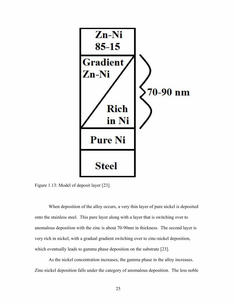
Figure 1.13: Model of deposit layer [23].
When deposition of the alloy occurs, a very thin layer of pure nickel is deposited
onto the stainless steel. This pure layer along with a layer that is switching over to
anomalous deposition with the zinc is about 70-90nm in thickness. The second layer is
very rich in nickel, with a gradual gradient switching over to zinc-nickel deposition,
which eventually leads to gamma phase deposition on the substrate [23].
As the nickel concentration increases, the gamma phase in the alloy increases.
Zinc-nickel deposition falls under the category of anomalous deposition. The less noble
25

metal, hereby zinc, deposits preferentially and the zinc concentration in the deposit is
higher then the ratio present in the plating bath [14].
1.3.8 Effects of Morphology for Acidic Deposits
Corrosion resistance is related to the morphology of the deposit more than the
composition. The best corrosion resistance was found for alloys with nodular grains of
measurable size. Alloys with elongated and non-measurable grains resulted in decreased
corrosion protection [5]. As grain size is reduced, corrosion protection is increased [25].
Although the corrosion resistance of zinc-nickel alloys is often believed to be strictly due
to the gamma phase alloy, it is also important to note the corrosion protection is also
dependent upon the structure of the deposit [26]. As a deposit grows in thickness, the
alpha phase begins to emerge, therefore thick deposits are not desirable [11].
The more compact the layers, the better corrosion protection they offer. Less
porous coatings offer greater corrosion resistance. Nickel being present in the coating
decreases the electrochemical activity of the coating, which extends its life [27].
Bajat et al. found that the nickel content of the alloy is not the only factor to
consider when studying good corrosion protection. The deposits with nickel content are
highest for direct current (DC) plating, and this leads to poor corrosion protection.
Corrosion protection is dependent upon differing surface morphology obtained by
different deposition parameters. For instance, the quicker the actual deposition the better
the deposit since irregularity of the deposits increases with time [15]. Introducing the
nickel into the system is advantageous because it makes the electrodeposited coatings
harder and less porous [27].
26

The deposits are characterized with a variety of techniques including SEM
(scanning electron microscopy), XRD (x-ray diffraction) and AAS (atomic absorption
spectroscopy). SEM is examined in many of the studies to determine surface
morphology and measure the thickness of the coatings [6, 11, 14, 28]. XRD is examined
to identify phases of the Zn-Ni alloys deposited. The composition of the electrodeposited
material is analyzed by dissolving the deposit in 3.0M HNO3, diluting to 100mL and
analyzed with atomic absorption spectroscopy [11, 27]. The Zn and Ni contents in the
deposit are confirmed by EDS (energy dispersive x-ray spectroscopy) [1, 14].
Scanning electron microscope (SEM) studies have demonstrated the temperature
dependence of the deposits from acidic bath conditions. A deposition performed at
25.0°C has non-uniform coatings and a large number of voids present in the film. At
35.0°C the deposit compactness has been increased and fewer voids are present. 40.0 °C
bath demonstrates a very uniform and compact deposit. The film has large grain size. A
deposit obtained from a 50.0°C temperature bath demonstrates a definite transition to a
fine grained structure and full surface coverage is also observed. It can be seen that
increasing the bath temperature from 25.0-50.0°C activates the nickel deposition which
leads to the alloy being deposited, a better surface coverage, and a better corrosion
resistive material [1].
1.3.9 Acid Deposition Conclusions
The shortcomings of acid bath deposition, most importantly the poor surface
coating lead the research to alkaline bath deposition. Acid baths are heavily dependent
upon bath conditions, such as pH, temperature and plating conditions. Acid bath
27
depositions readily produced both γ and δ phase alloys, while only γ phase alloy is
preferred for maximum corrosion protection.
1.4 Alkaline Bath Deposition
Alkaline bath deposition was examined once it was realized that acid baths do not
result in a uniform metal distribution. The first industrial alkaline system was developed
in 1992 and this deposit contained 5-7% nickel. This electrolyte solution contained
sodium hydroxide, zinc salts and amines acting as complexing agents. The advantage of
alkaline deposition was the deposit had superior alloy distribution compared to the acidic
deposition, but there was lower efficiency of the system which leads to longer deposition
times. The deposits appeared to be much duller in color, not the bright finishes obtained
during acidic deposition [7].
In 1995 the first high alloy (12-15% nickel) deposit process was patented. The
biggest advantage to this alloy was that it was much cheaper to process and easier to
control and had an increased corrosion resistance and enhanced wear [7].
Zinc-nickel alloys offer corrosion protection to stainless steel substrates because
they possess cathodic potential to the steel, controlled by the nickel in the deposit. An
increase in nickel concentration offers an increase in the corrosion potential. In alkaline
solutions the zinc-nickel has a corrosion potential of E=-1.0V versus SCE. Pure zinc has
a corrosion potential of -1.1V versus SCE and the corrosion potential of steel is E=-0.6V
versus SCE [4].
The nickel deposition is found to occur at the initial stages of deposition, within
the first 0.2 s of deposition compared to zinc. After this point, the deposition of nickel
28

greatly reduces, and after approximately 0.5 s the nickel content in the deposit is
constant, regardless of deposition time. This suggests that there is a pure nickel layer
between the alloy deposition and the stainless steel substrate [5]. Most work has been
done at pH › 12, with triethanolamine (TEA) acting as a complexing agent. Sodium
hydroxide is commonly used as the base. There is a zinc nickel ratio of approximately
6:1. Most work is done at room temperature [4].
1.4.1 Hydrogen Embrittlement of Deposits
Hydrogen is easily absorbed into metals during processing and once the finished
product is in use. Hydrogen negatively affects the ductility of metals and high levels of
hydrogen can cause metals to be brittle when subjected to constant stress [8].
When electroplating from aqueous solutions, hydrogen can be absorbed into the base
metal. Once a coating has been plated onto the metal, release of the hydrogen is difficult
because the coating is a barrier on the base metal. When the material is exposed to heat
the hydrogen escapes. This often destroys the coating in the process, due to fractures in
the material. The composition of the plating can be altered, resulting in a deposit that
allows for the escape of the hydrogen without destruction of the coating [29].
Alkaline bath deposits have been found to form open grained smooth deposits.
The porosity of the deposit is maximized which allows one to bake out the hydrogen
present in the metal, and diminish the post-plating embrittlement due to hydrogen. These
properties make this an optimal choice for both low and high strength steels [8].
Hydrogen gas evolution is very low when gamma phase has been deposited [30]. The
deposit is formed from more microstructure particles, so the hydrogen can easily escape
29

from the underlying metal without creating cracks and holes in the deposits, thereby
leading to better corrosion protection then with other alloy phases [25].
Pulse plating can lead to more of an opened grained structure, which is useful
because hydrogen can readily release out of the deposit without causing holes or pits in
the coating, so methods to obtain these types of structures are being examined [8]. Pulse
processes create more refined microstructures by inducing larger grain nucleation rates
therefore the corrosion properties of the zinc-nickel alloy can be improved by controlling
the nickel content in the pulse current process. With pulse plating, one is able to obtain
fine particles in a compact arrangement which gives a good appearance and high
hardness to the alloy [31].
1.4.2 Electrolytic Properties of the Alkaline Baths
In alkaline conditions, zinc is soluble as a hydroxyl complex (Na2Zn(OH)4).
Complexing agents are needed to keep the zinc and nickel in solution. Amines have been
found to be optimal ligands for nickel in alkaline solutions. The metal and amine
complex needs to result in a constant alloy composition independent of the current
density since this leads to good corrosion resistance [32]. As the zinc nickel ratio is
increased, the percentage of nickel in the coating decreases. With a ratio of greater than
7.5, a minor amount of nickel (<7%) is present in the alloy. With a ratio of 5 and less
nickel deposits of ≥10% are present. The optimal deposit is obtained with a zinc nickel
ratio of 5 to 7 [33]. Grain size, chromating ability and stability of the alloy composition
are all affected by the amine used. The working temperature of the cell has been a long
30

debated issue. As the temperature increases, the amount of nickel in the deposits
increases as well. Most cells are kept at or below a working temperature of 35°C [32].
Carbon dioxide gas can be readily absorbed into the system in alkaline solution
leading to carbonate contamination. To keep the amount of carbonate contamination at a
minimum, amine concentrations of less than 1 molar are used [32].
The Zn:Ni ratio has to be heavily controlled in the cell, or effects will be seen on
the composition of the alloy, the metal distribution, and the chromating effect of the
solution. The composition of the alloy is regulated by the Zn:Ni ratio, the total metal
content in the system, the base concentration and the bath temperature [32]. Composition
uniformity can be achieved when mass transfer is fast in relation to the electrode kinetics.
When these parameters are met, the surface concentrations of the reacting species in
solution remain essentially the same as in the bulk solution. In this case, the average
alloy composition is dependent upon the temperature and the bath composition due to
their effects on the electrode kinetics [5]. Higher nickel concentration in the bath
promotes anomalous codeposition [13].
At high overpotentials, and high current densities, zinc and zinc enriched phases
are obtained due to the high overpotential needed for zinc deposition [34].
31

Figure 1.14: Pourbaix diagram of zinc species.
Line 3’ in the Pourbaix diagram (figure 1.14) for zinc represents an equilibrium
reaction between Zn2+ and HZnO2- in solution, occurring at a pH value of 9.21. The 4’
line represents the equilibrium between HZnO2- and ZnO2
2- at a pH value of 13.11.
Carbon dioxide gas can be readily absorbed into the system in alkaline solution leading to
32

carbonate contamination [14], which could lower the pH of the solution enough to allow
the equilibrium of Zn2+ and HZnO2- to occur at a pH of 9.21 so the pH must be measured
regularly to remain slightly more alkaline than the equilibrium.
Figure 1.15: Pourbaix diagram of nickel species.
33

The Pourbaix diagram for nickel, as shown in figure 1.15, has one equilibrium
reaction at a pH value of 10.13 with Ni2+ in equilibrium with HNiO2-. This equilibrium
reaction should not be an issue because the pH range being examined is slightly less
alkaline. As you decrease the pH of the plating bath, the protection offered by the
coating is decreased because as the pH reaches more acidic conditions, the coating is not
as uniform, leading to areas of low to no protection on the underlying substrate from
corrosion [26] so it is important to still work in a higher pH range.
Ammonium hydroxide is often used as a complexing agent, because the ammonia
can easily complex the zinc and nickel in solution, and the hydroxide can offer the base
needed for alkaline deposition. The ammonia concentration needs to remain between
0.5-2M [31]. Below a concentration of 0.5M zinc oxides and zinc hydroxides precipitate
out immediately and above a concentration of 2M no deposition occurs [35].
1.4.3 Complexing Agents for Alkaline Baths
In the bath, zinc and nickel must be stabilized with some type of complexing
agent to prevent the precipitation of zinc and nickel hydroxides. Most alkaline bath work
has been done in alkaline solutions of pH›12, but some work has also been examined in
the 9.3-9.5 pH range. For a pH›12 range, triethanolamine (TEA) is commonly used as
the complexing agent. For the pH range of 9.3-9.5, ammonium hydroxide and sodium
citrate have been used. As the pH increases, the nickel content of the film decreases, as
more nickel hydroxide species are formed. The nickel content of the film also decreases
as the stirring speed is increased [9]. Deposits obtained from complex electrolytes have
finer grain deposits because of the higher overpotentials involved, which lead to more
34

nucleation then grain growth [36], so again a complexing agent is required to obtain a
better deposit.
1.5 Corrosion Protection from Alkaline Deposits
Zinc-nickel coatings have been studied because this alloy provides a strong
corrosion protection when plated onto steel. It has been shown that Zn-Ni alloys
containing 15-20% Ni possess up to four times more corrosion resistance then a
cadmium-titanium deposit on steel [6]. Many works have been found on the
electrodeposition of Zn-Ni onto steel to obtain improved resistance to corrosion [2, 3, 6].
It has been observed that when exposed to 400 hours of salt fog corrosion resistance,
zinc-nickel has outperformed corrosion resistance of pure zinc platings by 500% and
zinc-cadmium platings by 300%. The optimal Ni content has also been under a lot of
review, but throughout the papers it seems 8-15% Ni is the optimal range [27].
It has also been noted that the bath composition has an effect on the corrosion
resistance of the alloy, whereas the alkaline baths have a higher protection then acidic
baths. This is believed to be due to zinc oxide being infused into the coatings in the
alkaline systems [26].
35

Figure 1.16: Salt spray testing of zinc-nickel coating on steel substrate [26].
A: chromated Zn (barrel, acid bath) B: chromated Zn (rack, alkaline bath) C:
chromated Zn-Ni (barrel, acid bath) D: chromated Zn-Ni (rack, acid bath) E: chromated
Zn-Ni (rack, alkaline bath) F: chromated Zn-Ni (rack, alkaline bath).
Figure 1.16, salt spray testing of zinc-nickel coatings on steel substrates, shows
zinc corrosion products on the coatings of the plating as a function of time. The
chromated coatings show the best resistance overall, both in the time that the initial white
rust appears and in the rate of corrosion. It is also clear that the two types of alkaline bath
deposits are superior to the acid bath deposits. After exposure in the salt spray chamber,
the platings were x-rayed and the main corrosion product was found to be
ZnCl2.4Zn(OH)2 for all coatings [26].
36

1.5.1 Salt Spray Testing
The most common type of a corrosion resistance test is a salt spray test. The
plating is submerged in a salt solution, and the corrosion of the plating is measured over
time. 5% salt spray tests have been performed, which demonstrate the time elapsed for
white and red rust formation [33].
Figure 1.17: Salt spray corrosion tests [33].
37
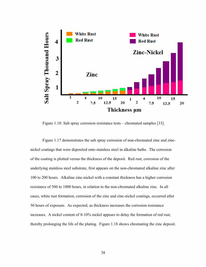
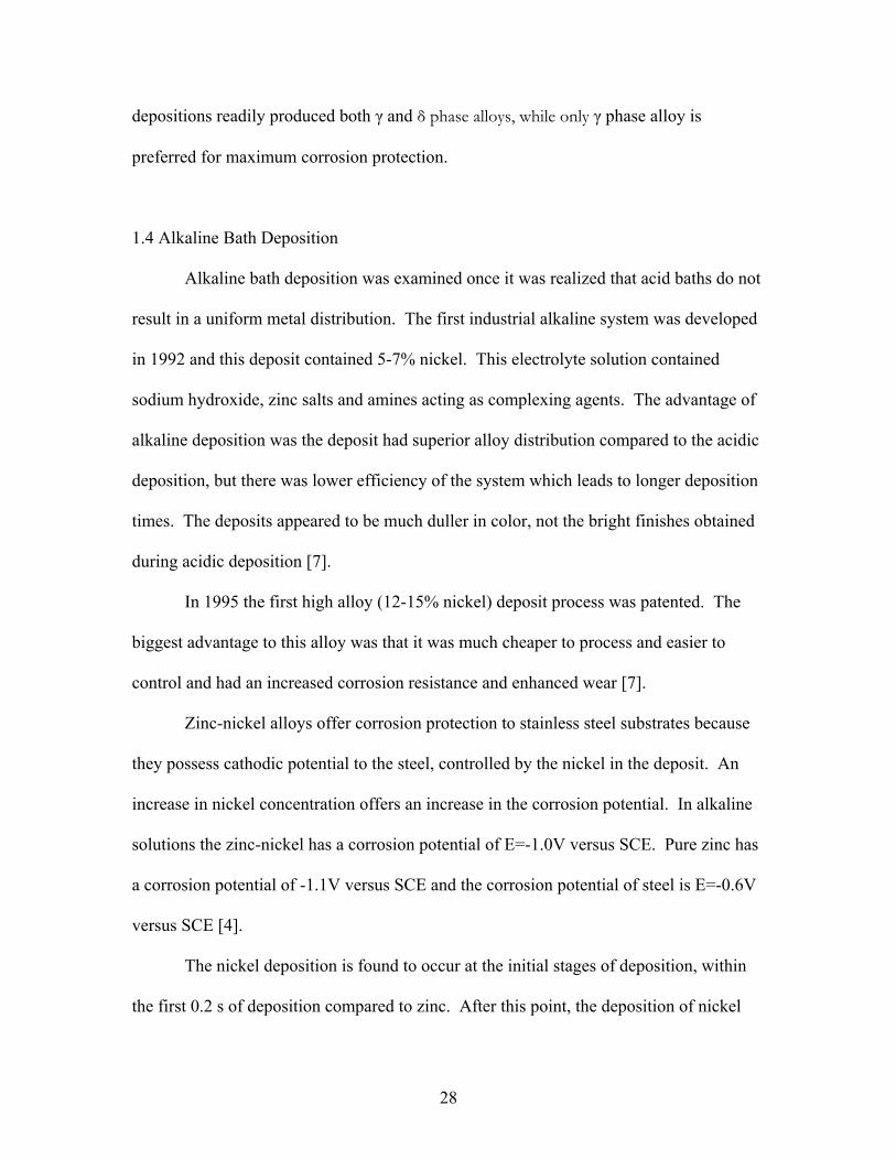
Figure 1.18: Salt spray corrosion resistance tests – chromated samples [33].
Figure 1.17 demonstrates the salt spray corrosion of non-chromated zinc and zinc-
nickel coatings that were deposited onto stainless steel in alkaline baths. The corrosion
of the coating is plotted versus the thickness of the deposit. Red rust, corrosion of the
underlying stainless steel substrate, first appears on the non-chromated alkaline zinc after
100 to 200 hours. Alkaline zinc-nickel with a constant thickness has a higher corrosion
resistance of 500 to 1000 hours, in relation to the non-chromated alkaline zinc. In all
cases, white rust formation, corrosion of the zinc and zinc-nickel coatings, occurred after
50 hours of exposure. As expected, as thickness increases the corrosion resistance
increases. A nickel content of 8-10% nickel appears to delay the formation of red rust,
thereby prolonging the life of the plating. Figure 1.18 shows chromating the zinc deposit.
38

It is seen that chromating extends the corrosion life for pure zinc. On chromated zinc-
nickel red rust did not appear before 500 hours of exposure [33].
1.5.2 Sacrificial Electrodes
Electrodeposited zinc alloys act as sacrificial electrodes, which means they
corrode preferentially (galvanic corrosion), which in turn protects the steel it has been
coated onto from corroding [28]. An alloy with a high enough zinc content could be
more stable than a pure zinc coating if it has a more negative potential then steel [27, 28].
Therefore, the corrosion stability of the zinc-nickel alloys is mainly dependent upon the
amount of nickel in the alloy. The higher the nickel content, the faster the coating
corrodes. It has been found that a nickel content of 8-15% is optimal for corrosion
protection.
1.5.3 Corrosion Phase
During the corrosion phase, while the zinc phase is being preferentially corroded,
internal stresses in the deposit increase which creates cracks throughout the plating.
Once these cracks form, there is a significant increase in the pH within the cracks which
is caused by cathodic reduction of the oxygen. The pH increase results in precipitation of
corrosion products which in turn fill in these cracks, thereby protecting the steel [26].
The oxidation of the zinc in the coating is slowed down by the presence of the nickel, but
as the oxidation increases, the nickel is present as a barrier to further corrosion [8]. The
coating is then a mixture of corrosion products with a nickel enriched alloy layer which
acts as a protection barrier to the steel substrate. The γ phase nickel is believed to be
39

primarily responsible for the corrosion protection properties of the alloy but overall the
protection also depends on the structural homogeneity of the plating [26]. Initially the
corrosion is sacrificial; the zinc corroding preferentially, but there is a gradual switch to
barrier protection by the nickel [8].
A nickel content of less than 15% is critical for sacrificial protection of the steel
to occur. Below 15% nickel content, the alloy follows the same corrosion mechanism of
pure zinc, corroding preferentially to the steel. Above 15% nickel the mechanism
follows that of a nickel deposit. The potential difference results in cathodic protection,
which, if the deposit becomes scratched, the base metal corrodes preferentially to the
plated deposit [8].
1.6 Summary
Due to the automotive industry there is a great push to improve the corrosion
resistance of steel, and this can be accomplished with the electrochemical deposition of
zinc-nickel alloys onto steel. For many years zinc coated stainless steel has been used in
this field. Zinc sacrificially corrodes compared to the stainless steel, thereby protecting it
[1]. Zinc alloys are of great interest in research because they offer a greater resistance to
corrosion then pure zinc [2]. Zinc-cadmium alloys have been used for the corrosion
protection of steel to date but due to the harsh environmental conditions associated with
cadmium, other metals have been examined. The use of cadmium has become very
regulated, or in some countries banned all together. At this point, alloys were examined
as a solution to the problem. Alloys have different corrosion potentials then their single
elements; therefore by picking the correct combination of alloys, one can greatly increase
40

the corrosion resistance of the material [1] and zinc-nickel is a cheap environmentally
milder alternative.
It has been shown that Zn-Ni alloys containing 15-20% Ni possess up to four
times more corrosion resistance then a cadmium-titanium deposit on steel [3]. When
exposed to 400 hours of salt fog (a common method used to test corrosion protection),
Zn-Ni has outperformed zinc platings by 500% and zinc-cadmium platings by 300% [5].
Historically acidic depositions have been performed, with a zinc nickel alloy ratio
of 10-15% nickel in the deposit. Acid bath deposition had one major drawback, which
was the creation of non-uniform deposits [5]. The advantage of alkaline deposition is the
deposit has superior alloy distribution compared to the acidic deposition, but there is
lower efficiency of the system which leads to longer deposition times.
1.6.1 This Thesis Work
Alkaline electodeposition gives a more uniform deposit, which leads to better
corrosion protection of the underlying metal, so a new method will be developed for the
co-deposition of zinc-nickel alloys at lower pH values (9-9.5 range) and room
temperatures rather then the current elevated temperatures employed. To date, work has
been performed with sodium hydroxide at caustic pH values (≥12) and at higher then
room temperatures. There has been a push for the use of less caustic solutions towards a
more neutral pH. Our method will use ammonium hydroxide as a base source, which is
less caustic then sodium hydroxide, at a lower pH range of 9.3-9.5, and room
temperature. The deposits obtained will contain the same qualities of deposits from more
difficult working conditions. The conditions to be developed will be easier to perform
41

under normal laboratory conditions and this technique will easily be integrated into
industry to continue the battle against corrosion.
Due to the highly caustic properties of alkaline baths in the pH›12 range our
research work has focused on a lower but still alkaline pH range of 9.3-9.5. Based on the
Pourbaix diagrams, there are a few reactions that may affect us in this range.
Ammonium hydroxide will be examined for its use both as a base source and a
complexing agent for zinc and nickel ions in solution. In alkaline conditions, zinc is
soluble as a hydroxyl complex (Zn(OH)4) but will still readily precipitate out of solution
if not agitated during deposition. Nickel must also be complexed in solution to prevent
the precipitation of nickel hydroxides. Amines have been found to be optimal ligands for
nickel in alkaline solutions but this work will examine the use of other ligands, such as
acetate, which are more environmentally friendly. The use of common electrolytes in
solution to aid in deposition of the metal alloy will also be examined. The range of pH
values to be examined will be 9.3-9.5, which is still in the alkaline range, but offers
milder working conditions.
A deposition method for the co-deposition of zinc-nickel alloys onto stainless
steel will be developed. This technique will offer better corrosion protection and will be
easier to apply on the macro scale of industry. The optimal nickel percentage in the alloy
when deposited from a non-acidic pH bath will also be determined, since, as to date this
has not been discussed. The best bath conditions for optimal zinc-nickel deposition will
be determined.
42

CHAPTER 2
DEPOSITION OF PURE METAL FILMS IN ALKALINE SOLUTIONS
2.1 Introduction
The depositions of pure zinc metal and pure nickel metal in alkaline solutions
were examined to determine the optimal plating conditions for pure metal films. Pure
metal deposition was important because if optimal conditions could be determined for
pure metal deposition, these parameters could be applied to alloy deposition. Alloy
deposition is usually at a shifted potential in relation to the pure metals, but in the case of
zinc and nickel alloys, the deposition of the alloy occurs at potentials between the
deposition of pure nickel and pure zinc. The alloy shifts the deposition potential from the
original pure metal potential for the metals present in the alloy phase. Complexing
ligands were required to keep the metal ions in solution, because the metals readily
precipitated out as hydroxide species, so different ligands were examined based on their
pKa’s with the metal complex. Borate was also examined as a possible electrolytic
solvent since nickel is known to deposit well from borate systems.
All deposits were obtained by a potentiostatic method, both from a direct potential
method and from a potential step method. The deposits obtained through a potential step
method demonstrated more uniform and better adhering deposits.
43

Figure 2.1: Potential step method diagram.
Figure 2.1 represents the potential step method employed for deposition. The E1
value was determined based on where nucleation of the metal began to occur on the
substrate, by picking a value past the crossover point in the cyclic voltammogram (CV).
The E2 value was determined by picking a value more positive then E1, but still to the
cathodic side of the stripping peak present for the metal. The purpose of performing the
potential step method was to obtain a better surface plating of the metal. Once the
nucleation of the metal onto the substrate began, the system was quickly brought back
down to the lower potential. This brought the metal that was being plated onto steel as
M0, back into solution as M2+. The system was then brought back up to the higher
potential, thereby creating more metal nucleation sites on the already populated substrate
surface. It was found that this method did result in a better metal deposit for both zinc
and nickel depositions.
44

2.2 Experimental Parameters
All electrochemical work was performed on an EG&G PARC
Potentiostat/Galvanostat Model 273A. The cell set up was as follows:
Figure 2.2: Set up of electrochemical cell.
The working electrode used throughout all experiments was a stainless steel disc
mounted in epoxy. The working electrode was polished with grit paper, diamond and
alumina until the steel had a mirror finish. The disc was bound to copper wire through an
electroconducting silver epoxy, and the copper wire was connected to the lead. The disc
was set into epoxy and hardened for 24 hours. The counter electrode used throughout the
experiments was a chromel coiled wire and the reference electrode was a saturated
calomel electrode (SCE, +0.241V vs. SHE).
Cyclic voltammograms (CV) were run on all electrochemical solutions prepared
with an EG & G PARC Potentiostat/Galvanostat. Based on the CV’s, the deposits were
plated onto the stainless steel discs at set potentials. X-ray patterns of these deposits were
examined to determine the content of the deposit. The XRD data was obtained on a
Siemens D-500 Diffractometer using a Cu Kα radiation (λ=0.1541 Å, 35kV, 24mA). The
45
scans were run on a θ:2θ coupled experiment, from 10 to 100°, step size of 0.05 degrees
and dwell time of 1 second.
A great deal of work in the literature has been done on alkaline systems with a pH
> 12, with sodium hydroxide used as the base. Some work has been performed with
ammonium hydroxide acting as the base. This work focused on the use of ammonium
hydroxide as the base because once sodium hydroxide was added to the system, the
metals precipitated out almost immediately as metal hydroxides. A suitable complexing
agent was not found to work with sodium hydroxide. The ammonium hydroxide also
only requires a pH range of 9.3 to 9.5, so it was preferential to work in these less harsh
conditions.
Background XRD patterns of the stainless steel disc in and out of epoxy are
attached to demonstrate the background that is expected in the deposits.
40 60 80 100
0
200
400
600
800
1000
1200
20=8
2.29
91, S
tain
less
Ste
el 2
11 P
eak
20=6
4.78
61, S
tain
less
Ste
el 2
00 P
eak
20=4
4.64
99, S
tain
less
Ste
el 1
10 P
eak
Inte
nsity
(CP
S)
2 Theta (degrees)
Figure 2.3: Stainless steel disc background mounted in epoxy.
46

Figure 2.3 is a scan of this background peak, which shows the stainless steel
peaks of the substrate. From the peaks observed, it is clear there are three main peaks
present for stainless steel in the XRD pattern. A peak at approximately 98.879 degrees is
expected for the steel 220 plane but was not observed due to the epoxy background noise.
40 60 80 100
0
50
100
150
200
250
20=9
8.87
33, S
tain
less
Ste
el 2
20 P
eak
20=8
2.17
17, S
tain
less
Ste
el 2
11 P
eak
20=6
4.84
82, S
tain
less
Ste
el 2
00 P
eak
20=4
4.59
90, S
tain
less
Ste
el 1
10 P
eak
20=2
9.46
38, S
tain
less
Ste
el P
eak
Inte
nsity
(CP
S)
2 Theta (degrees)
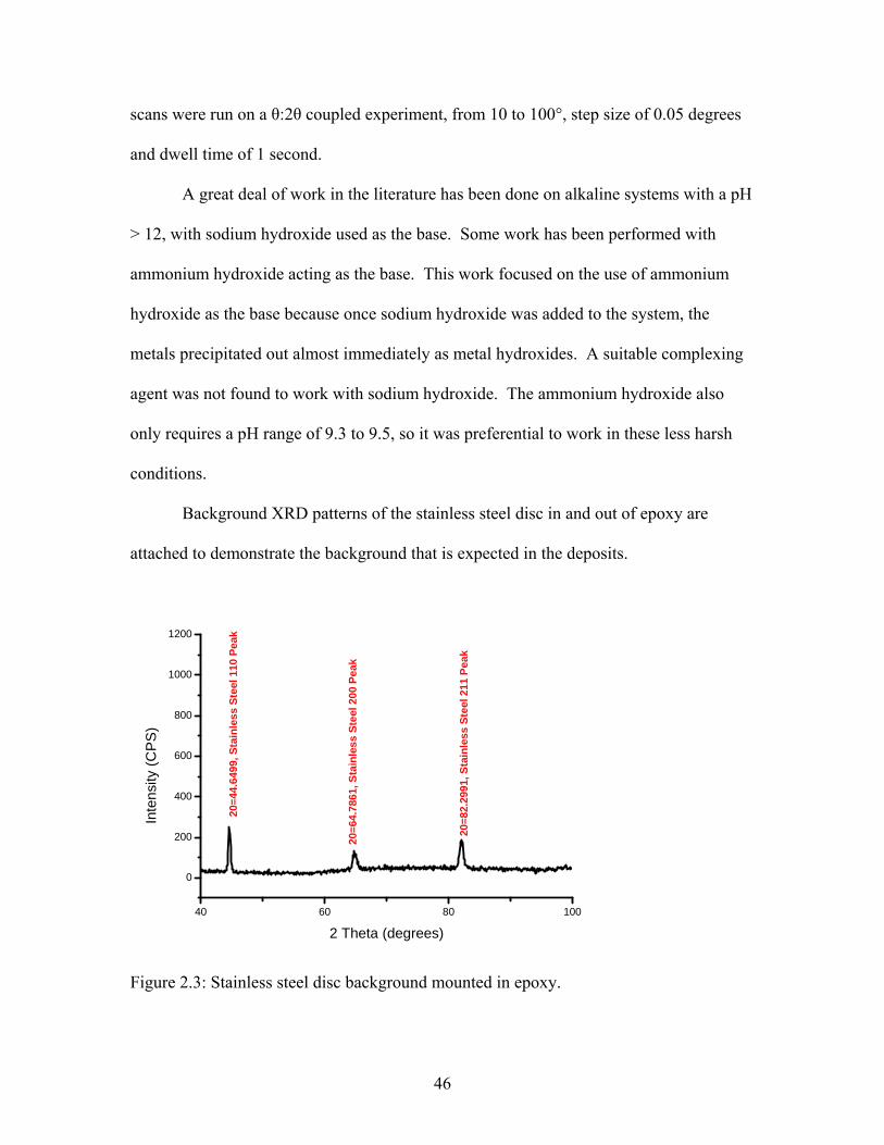
Figure 2.4: Stainless steel background disc, out of epoxy.
This XRD pattern (figure 2.4) shows the stainless steel background disc out of the
epoxy setting. The disc had been removed from the epoxy prior to running the XRD
pattern. Figure 2.4 clearly illustrates the main peaks expected for stainless steel in the 10
to 100 degree 2 theta range. The 220 peak present at 98.8733 is now observed; in the
epoxy setting (figure 2.3) this peak was lost to background noise.
47

Based on the following x-ray diffraction patterns, it is clear that nickel and zinc
have been deposited from a variety of electrochemical bath conditions.
2.3 Zinc Sources for Deposition
Zinc nitrate and zinc sulfate monohydrate have been examined as depositing salts for
pure zinc deposition. Zinc sulfate monohydrate was favored in this work because it more
readily dissolves in aqueous solutions. Zinc nitrate dissolves nicely in aqueous solutions
but no deposition appears to occur during plating. Hubert et al. noted that for zinc
compounds, an ammonia concentration must be set between 0.5M and 2M for deposition
to occur. Below 0.5M the metal will precipitate out immediately as a hydroxide and
above 2M no deposition is observed [31]. The ammonium hydroxide concentration for
this work was set at 1M, but the zinc still precipitated out upon addition of ammonium
hydroxide. When hydroxide was added to the zinc solution, a white precipitate
immediately formed. This solid is believed to be a mixture of zinc oxide and zinc
hydroxide. Consequently, the following ligands were examined to complex the zinc in
solution to stabilize the Zn2+ ions. These ligands were examined with zinc nitrate and
zinc sulfate monohydrate.
Table 2.1: Possible ligands for zinc; zinc complex pKa’s. Ligand pKa1 pKa2 pKa3 pKa4 Ammonia 2.37 4.81 7.31 9.46 Acetate 1.5 Tartaric Acid 2.68 8.32 Triethanolamine 2.00
48

Figure 2.5: Structure of zinc ammonia complex.
Figure 2.6: Structure of zinc tartaric acid complex.
Figure 2.7: Structure of zinc acetate complex.
49

Figure 2.8: Structure of zinc triethanolamine complex.
Throughout the literature, zinc was complexed with triethanolamine to keep it in
solution. TEA was examined as a possible ligand for zinc along with tartaric acid, lactic
acid, and ammonia from ammonium hydroxide. Zinc sulfate heptahydrate was the most
commonly used zinc source for zinc-nickel codeposition in the literature, but zinc nitrate
and zinc sulfate monohydrate were examined as possible zinc sources in this work. Zinc
sulfate monohydrate dissolved more readily in water and therefore was an easier choice
in an aqueous solution.
Based on the JCPDS Database, the following peaks should be observed for zinc
metal, in a random pattern.
Table 2.2: The PDF data of XRD patterns of standard zinc metal from the JCPDS Database (PDF #04-0831). 2θ hkl I/I0 36.296 002 53 38.992 100 40 43.231 101 100 54.336 102 28 70.056 103 25 70.661 110 21 77.027 004 2 82.102 112 23 83.765 200 5 86.557 201 17 89.920 104 3 94.900 202 5
50

2.3.1 Zinc Nitrate
Figure 2.9: Zinc nitrate.
Zinc nitrate was examined as a possible zinc source because it readily dissolved in
aqueous solutions. Initially the zinc nitrate was dissolved in water and the solution was
brought to a pH of 9.3 with ammonium hydroxide as the base. When zinc nitrate was
combined with ammonium hydroxide, a white precipitate formed upon immediate
addition of the base. This precipitate was believed to be a form of zinc hydroxide. After
initial research with this molecule, it was clear a complexing ligand would be required to
stabilize the zinc in solution. Tartaric acid and lactic acid were examined as possible
ligands for this molecule. Initially zinc nitrate was complexed with tartaric acid. The
tartaric acid seemed to complex the zinc in solution, but once base was added a white
precipitate formed. Zinc nitrate was also studied with lactic acid but the lactic acid did
not appear to plate the zinc metal onto the stainless steel disc. Zinc nitrate was not
examined with triethanolamine as the ligand.
51

The following solutions were prepared and examined:
Solution 1: 0.5 M Zinc Nitrate and 1M NH4OH at pH=9.3
Solution 2: 0.5 M Zinc Nitrate, 0.5M Tartaric Acid, 1M NH4OH at pH=9.3
-1 0 1
0.012
0.010
0.008
0.006
0.004
0.002
0.000
-0.002
Cur
rent
(A)
Potential (V)
Zinc Stripping Peak E=-0.900V
Crossover E=-1.0945V
Figure 2.10: CV of zinc nitrate, pH=9.3 with 1M NH4OH.
Zinc Nitrate was made basic (pH=9.3) with NH4OH and a cyclic voltammogram
(CV) (figure 2.10) was ran on this solution. The Zinc nitrate does not remain in solution
upon the addition of base; a white precipitate immediately formed which appeared to be a
zinc oxide/zinc hydroxide mixture. There is a clear stripping peak at E= -0.900V and a
crossover at E=-1.0945V. The crossover represents metal deposition nucleation sites
52
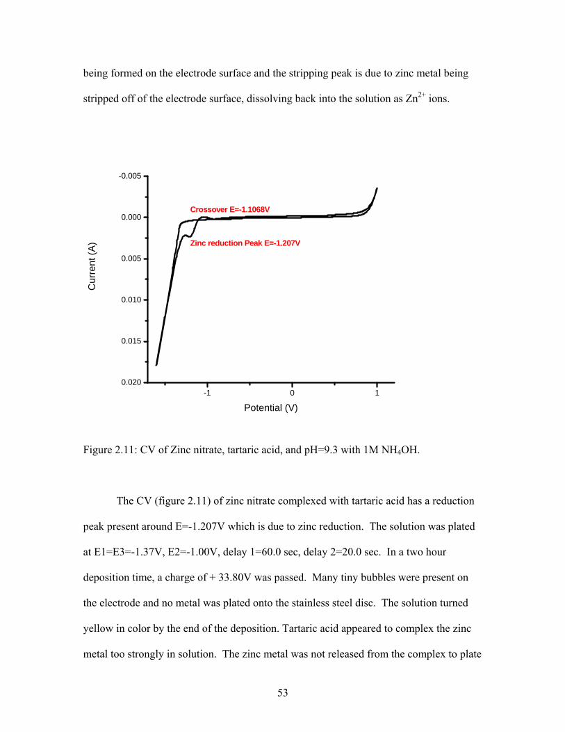
being formed on the electrode surface and the stripping peak is due to zinc metal being
stripped off of the electrode surface, dissolving back into the solution as Zn2+ ions.
-1 0 10.020
0.015
0.010
0.005
0.000
-0.005
Cur
rent
(A)
Potential (V)
Zinc reduction Peak E=-1.207V
Crossover E=-1.1068V
Figure 2.11: CV of Zinc nitrate, tartaric acid, and pH=9.3 with 1M NH4OH.
The CV (figure 2.11) of zinc nitrate complexed with tartaric acid has a reduction
peak present around E=-1.207V which is due to zinc reduction. The solution was plated
at E1=E3=-1.37V, E2=-1.00V, delay 1=60.0 sec, delay 2=20.0 sec. In a two hour
deposition time, a charge of + 33.80V was passed. Many tiny bubbles were present on
the electrode and no metal was plated onto the stainless steel disc. The solution turned
yellow in color by the end of the deposition. Tartaric acid appeared to complex the zinc
metal too strongly in solution. The zinc metal was not released from the complex to plate
53

the steel with a zinc coating. The second pKa of the zinc-tartaric acid complex is 8.32,
which is too strong of an attraction to release the zinc ion into solution for metal
deposition.
2.3.1.1 Zinc Nitrate Conclusions
Zinc nitrate does not work as a zinc source in basic solution. The zinc does not
plate out as pure metal, no platings were obtained from the baths with zinc nitrate. Zinc
nitrate readily precipitates out of solution when not complexed with a ligand, even when
using ammonium hydroxide as the base source. When using tartaric acid the solution
turned yellow in color, but no deposition was observed.
2.3.2 Zinc Sulfate Monohydrate
Figure 2.12: Zinc sulfate monohydrate.
Zinc sulfate monohydrate was also examined as a possible zinc source. Initially,
the zinc sulfate monohydrate was combined with pure sodium hydroxide as the base
source. However, the zinc precipitated out immediately as a white precipitate. The zinc
sulfate monohydrate was also combined with ammonium hydroxide without any
54

complexing ligand but, again, the zinc was immediately precipitated out as a white solid.
A complexing agent was then examined to combine with the zinc sulfate monohydrate to
keep it in solution. Triethanolamine and sodium acetate were used as possible
complexing ligands for the zinc sulfate monohydrate. When complexed with
triethanolamine during electrodeposition, big bubbles formed on the electrode surface
and no deposit appeared to form. Acetate appeared to be the best ligand to use based on
the appearance of the deposits. The zinc/acetate solution needed to be stirred during
plating or a white precipitate fell out of solution.
The following solutions were prepared and examined:
Solution 1: 0.5 M ZnSO4.H20, 0.5M Triethanolamine, 1M NH4OH at pH=9.3
Solution 2: 0.5 M ZnSO4.H20, 0.5M Sodium Acetate, 1M NH4OH at pH=9.3
-1.5 -1.0 -0.5 0.0 0.5 1.0
0.020
0.015
0.010
0.005
0.000
-0.005
Crossover occurs at E= -1.306V
Crossover occurs at E= -1.174V
Zinc Stripping Peak E=-0.9986V
Cur
rent
(A)
Potential (V)
Figure 2.13: CV of Zinc sulfate monohydrate, triethanolamine with pH=9.3 with 1M
NH4OH.
55

The CV (figure 2.13) curve of zinc sulfate monohydrate and
triethanolamine with a pH=9.3 with 1M NH4OH showed a strong zinc stripping peak at
E=-0.996V. There were two crossovers occurring, both just past the reduction peak of
the zinc metal in solution. The first crossover was present at E= -1.174V, the second
crossover was present at E= -1.306V. A plating of this solution was performed at E= -
1.200V, which was between the two crossover peaks present in the CV. The solution was
stirred during deposition. The deposition lasted 6 hours and +7.770 C was passed with
current of +0.820mA to +0.301mA at the end of the deposition. After plating, white dots
were present on the electrode surface. No actual metal deposit was formed which was
confirmed by XRD. Powder formed at the bottom of the beaker and a solid precipitate
formed on the top of the liquid.
40 60 80 100
0
200
400
600
800
1000
1200
20=8
2.54
97, S
tain
less
Ste
el 2
11 P
eak
20=6
5.09
49, S
tain
less
Ste
el 2
00 P
eak
20=4
4.92
90, S
tain
less
Ste
el 1
10 P
eak
Inte
nsity
(CP
S)
2 Theta (Degrees)
Figure 2.14: XRD Pattern of zinc sulfate monohydrate, triethanolamine, and pH=9.3 with
1M NH4OH.
56

The electrode was x-rayed and the XRD pattern (figure 2.14) of zinc
sulfate monohydrate with the complexing agent of triethanolamine did not show any zinc
present in the pattern. The disc after plating did not appear to have any metal deposited
onto the steel.
-2.0 -1.5 -1.0 -0.5 0.0 0.5 1.00.010
0.008
0.006
0.004
0.002
0.000
-0.002
-0.004
-0.006
-0.008
Crossover occurs at E=-1.328V
Zinc Reduction Peak, E=-1.237V
Cur
rent
(A)
Potential (V)
Figure 2.15: CV of zinc sulfate monohydrate and triethanolamine, pH=11.04 with 1.5M
NH4OH.
The CV (figure 2.15) of zinc sulfate monohydrate when complexed with
triethanolamine, and brought to an overall pH of 11.04 with ammonium hydroxide
showed a zinc stripping peak at E= -1.237V. A crossover occurred at E= -1.328V. The
solution was greenish yellow in color, and a brown precipitate formed over time. The
57

solution was plated at a potential of E= -1.3V but nothing plated onto the electrode and
large bubbles covered the electrode surface during the deposition time.
-2.0 -1.5 -1.0 -0.5 0.0 0.5
0.04
0.03
0.02
0.01
0.00
-0.01Zinc Stripping peak E=-1.02V
Cur
rent
(A)
Potential (V)
Figure 2.16: CV of zinc sulfate monohydrate and sodium acetate, pH=9.3 with 1M
NH4OH.
The CV (figure 2.16) of zinc sulfate monohydrate, sodium acetate, pH=9.3 with
ammonium hydroxide had a stripping peak at E= 1.02V. This CV appeared to have a
crossover but upon closer examination, no crossover actually occurred. This solution was
plated at a potential of E= -1.450V. The solution was stirred. The charge passed was
+20.19C in 45 minutes, with the current beginning at +14.61mA and dropping to
+8.00mA at the end of the deposition.
58

The plating of zinc sulfate, sodium acetate had a very smooth, silver deposit on
the stainless steel. The metal was examined with x-ray diffraction (figure 2.15) to
confirm the presence of zinc metal on the electrode.
40 60 80 100
0
500
1000
1500
2000
20=9
5.14
14, Z
inc
202
Peak
20=8
6.47
96, Z
inc
201
Peak
20=8
2.17
17, Z
inc
112
Peak
Stai
nles
s St
eel 2
11 P
eak
20=7
0.16
96, Z
inc
103
and
110
Peak
s
20=6
4.84
82, S
tain
less
Ste
el 2
00 P
eak
20=5
4.43
56, Z
inc
102
Peak
20=4
4.59
90, S
tain
less
Ste
el 1
10 P
eak
20=4
3.42
41, Z
inc
101
Peak
20=3
9.09
32, Z
inc
100
Peak
20=3
6.32
88, Z
inc
002
Peak
20=2
9.44
5, S
S Pe
ak
Inte
nsity
(CP
S)
2 Theta (Degrees)
Figure 2.17: XRD pattern of zinc sulfate monohydrate with sodium acetate, pH=9.32
with 1M NH4OH.
It was clear from the XRD pattern (figure 2.17) of the zinc/acetate deposit that
zinc metal had been deposited onto the steel electrode. The XRD pattern was a plating of
zinc sulfate monohydrate, complexed with sodium acetate and brought to a pH=9.32 with
ammonium hydroxide, plated onto a stainless steel disc. The x-ray pattern of the zinc
sulfate monohydrate was from a plating obtained at a potential of E= -1.450V. The x-ray
pattern was of the deposit still adhered to the stainless steel substrate, but had been
removed from the epoxy.
59

Zinc deposition was confirmed in the deposit. Based on JCPDS database, powder
diffraction file (PDF) 04-0831, zinc was deposited in a random pattern. The stainless
steel peaks have minimal intensities in the x-ray pattern, thereby demonstrating a thick
zinc deposit on the steel disc.
2.3.2.1 Zinc Sulfate Monohydrate Conclusions
Zinc sulfate monohydrate is a great source for zinc deposition from alkaline baths.
Zinc sulfate monohydrate readily plated out of solution with the addition of an acetate
complexing ligand in solution. Zinc sulfate monohydrate will be examined further as a
possible zinc source in the deposition bath.
2.4 Borate Solutions for Zinc
Borate was examined as a possible electrolyte for the deposition solutions due to
the advantages of using borate when depositing pure nickel metal. A solution of 0.1M
borate was used consistently throughout the following experiments. An advantage to
using borate is no complexing ligand is required for deposition, past the ammonium
ligand provided by the base source.
60

2.4.1 Zinc Sulfate Monohydrate in Borate
-2 -1 0 1
0.01
0.00
Cur
rent
(A)
Potential (V)
Crossover E=-1.0700V
Zinc Reduction Peak E=-0.8055V
Figure 2.18: CV of 0.5M Zn in 0.1M borate, pH=9.3 with 1M NH4OH.
Based on the CV (figure 2.18) of zinc in borate, there is a zinc stripping peak
present at E=-0.8055V and a crossover at E=-1.0700V. The solution was deposited based
on previous experiments with E applied=-1.450V and the solution was continuously
stirred slowly to keep precipitate from collecting. Metal was deposited but had a very
weak adhesion to the metal; flakes were readily falling off the electrode substrate. A
charge of + 111.3C was passed with a current range of +5.350mA to + 4.570mA.
61

30 35 40 45 50 55 60 65 70 75 80 85 90 95 10050
100
150
200
250
300
350
400
450
500
550
600In
tens
ity (C
PS)
2 Theta (degrees)
36.4
Zn
002
39.2
Zn
100
43.3
Zn
101
54.5
Zn
102
82.1
Zn
112,
SS
211
70.3
Zn
103,
Zn
110
Figure 2.19: XRD pattern of zinc deposited from 0.1M borate solution, pH=9.3 with 1M
NH4OH.
Zinc is confirmed in the deposit from the zinc borate solution (figure 2.19); the
zinc has been deposited in a random orientation. There is not a lot of zinc present in the
deposit, because the metal flakes were readily falling off the electrode. A pulse plating
method was used with the zinc borate solution and the deposit had much better adhesion
to the stainless steel substrate.
2.4.1.1 Zinc Sulfate Monohydrate conclusions for borate solutions
Zinc sulfate monohydrate was readily deposited as a pure zinc coating onto
stainless steel from a borate electrolytic solution. When using a borate solution, the zinc
metal initially fell off the stainless steel substrate, obtained from a direct potential
62

method. A step potential method was used and a thick zinc coating with a strong
adhesion to the underlying stainless steel substrate was obtained.
2.5 Nickel Sources for Deposition
Nickel sulfate hexahydrate and nickel ammonium sulfate hexahydrate were both
examined as possible nickel sources for the alloy. Nickel is able to deposit at a lower
overpotential than zinc, so the parameters used for zinc deposition were also employed
for the deposition of nickel.
Nickel sulfate hexahydrate is commonly used as the nickel source for zinc-nickel
codeposition. Initially, aqueous solutions of nickel sulfate hexahydrate were prepared
and combined with sodium hydroxide and ammonium hydroxide respectively. Nickel
hydroxide precipitated out immediately when combined with sodium hydroxide or
ammonium hydroxide. A complexing agent was required to keep the nickel from
precipitating out as nickel hydroxide in basic solution. The most commonly used
complexing agent in alkaline solutions is triethanolamine (TEA). TEA was examined as
a possible ligand along with sodium acetate and lactic acid. Nickel sulfate hexahydrate
was complexed with sodium acetate to keep it in solution in order to plate the nickel
metal onto the stainless steel disc.
Sodium acetate was used as the complexing ligand, because of the ligands
examined for zinc, it was the only one to allow for deposition of zinc, and it is a common
ligand between the 2 metal systems, which will simplify the system when the metals are
combined for deposition. The nickel complex solution appeared green in color. Upon
addition of ammonium hydroxide; light green precipitate slowly began to form and the
63

solution turned blue in color. The solutions were stirred slowly during deposition to keep
the nickel in solution. If the solution was left over time before deposition, the solution
would turn back to green in color with a decrease in the pH indicative of carbon dioxide
absorbing into the solution.
Based on the JCPDS Database, the following peaks should be observed for nickel
metal, in a random pattern.
Table 2.3: The PDF data of XRD patterns of standard nickel metal from the JCPDS Database (PDF#04-0850) PDF#04-0850- JCPDS Database. 2θ hkl I/I0 44.507 111 100 51.846 200 42 76.370 220 21 92.944 311 20 98.446 222 7
2.5.1 Nickel Sulfate Hexahydrate
In nickel sulfate hexahydrate, the water molecules are bound to the nickel and the
sulfate ion is loosely associated through hydrogen bonding to the nickel center.
Figure 2.20: Nickel Sulfate Hexahydrate Structure.
64

In most previous work, sodium hydroxide was used as the base source for alkaline
deposition with a pH›12. Some work has been examined in a pH range of 9.3-9.5; where
ammonium hydroxide was used as the base source for most experiments. For this work,
both pH ranges were examined. Nickel sulfate hexahydrate when combined with
ammonium hydroxide or sodium hydroxide formed nickel hydroxide upon being mixed.
The nickel hydroxide was a green powder. Nickel sulfate hexahydrate was complexed
with a number of ligands to withstand the basic environment required for deposition. The
main base used was ammonium hydroxide with a pH range of 9.3-9.5 to avoid the
harsher conditions associated with a pH›12.
Table 2.4: Possible ligands for nickel; nickel complex pKa values. Ligand pKa1 pKa2 pKa3 pKa4 pKa5 pKa6 Ammonia 2.80 5.04 6.77 7.96 8.71 8.74 Acetate 1.12 1.81 Triethanolamine 2.7
Figure 2.21: Nickel ammonia.
65

Figure 2.22: Nickel acetate.
Figure 2.23: Nickel triethanolamine.
In previous work, it was stated that ammonia was used as the complexing agent
for nickel, specifically in the form of ammonium hydroxide. The ammonium hydroxide
was used as the ligand source and the base source. Once the ammonium hydroxide was
added to the nickel solution, the nickel precipitated out immediately, so this was not
examined as a possible ligand source.
66

The following solutions were prepared and examined:
Solution 1: 0.5 M NiSO4.6H20, 0.5M Sodium Acetate, 1M NH4OH at pH=9.3
Solution 3: 0.5 M NiSO4.6H20, 0.5M Triethanolamine, 1M NH4OH at pH=9.3
Sodium acetate appears to be the best possible ligand of those examined. With
the acetate, the nickel remained in solution upon the addition of hydroxide, but the
acetate released the nickel when the potential reached deposition conditions.
Nickel sulfate hexahydrate, with sodium acetate acting as a complexing agent,
appeared to stay in basic solution (with ammonium hydroxide) well over time without
stirring. Although the acetate did appear to keep the nickel in solution, the deposit was
very rough and uneven. A pulse method was attempted to obtain a more uniform surface
morphology. Pulse current plating and rotating disc electrode experiments have been
found to give better deposits. Pulse current plating has been examined as a possible
technique to increase adhesion to the stainless steel substrate. In the literature review, it
was noted that nickel deposits tend to be uneven in morphology due to hydrogen
embitterment [8]. Pulse plating was used where the shorter on-time resulted in more
durable plating. A deposit needs to be formed that allows for the release of hydrogen gas
upon heating, and with the smaller grain sizes this was possible without destruction of the
coating.
67

-2.0 -1.5 -1.0 -0.5 0.0 0.5 1.00.05
0.04
0.03
0.02
0.01
0.00
-0.01
Crossover occurs at E= -0.6715V
Stripping peak=-0.4542V
Cur
rent
(A)
Potential (V)
Figure 2.24: CV of nickel sulfate hexahydrate, sodium acetate, and pH=9.32 with 1M
NH4OH.
The stripping peak of nickel was observed at E= -0.4542V in figure 2.24 for the
CV of nickel sulfate hexahydrate with sodium acetate at a pH=9.32 with 1M NH4OH,
which is what is expected for nickel. A crossover occurred in the CV at E= -0.6715V.
The crossover represents the point at which the nickel began to form nucleation sites on
the stainless steel substrate. Upon running the CV, small amounts of nickel were plated
onto the working electrode once the scan was completed. Based on this CV (figure 2.24)
nickel sulfate hexahydrate/sodium acetate with pH=9.3 with 1M NH4OH was plated onto
a stainless steel disc at E1=-1.350V, E2=-0.275V using a pulse waveform. The delay time
was 1 second for each potential, and the solution was not stirred. A charge of +20.08C
was passed in 18 minutes with current ranging from +31.6 to +37.4mA.
68

The deposition potentials were determined based on the CV of the solution. E1
began just past where the lines appeared to crossover, meaning, where nucleation began
to occur. E2 was just before the reduction peak present for the nickel in the solution.
With this method, it was hoped that a uniform layer of nickel would be formed on the
stainless steel disc, and then when brought to the lower potential, some of the top layer of
this deposit would be removed. When the potential was then brought back to the higher
value, the nucleation would again commence on this smoother surface, and a smoother
deposit would be created.
The nickel sulfate hexahydrate, sodium acetate solution was plated at a high
potential to ensure a deposit was formed. At lower potentials, although the stripping peak
of nickel was observed around E=-0.45V, no deposit formed. Small amounts of
precipitate formed onto the steel disc of the working electrode, but upon closer
examination, it appeared to just be base precipitate formed on the electrode surface.
Nickel deposited nicely at the higher potentials (above + 1.1V approximately), but the
deposit did not adhere well to the steel disc. The surface of the deposit seemed very
uneven and the plating occurred very quickly, usually in 30 minutes or less.
69

40 60 80 100
0
200
400
600
800
1000
1200
1400
20=9
8.48
17, N
icke
l 222
Pea
kS
tain
less
Ste
el 2
20 P
eak
20=9
2.97
60, N
icke
l 311
Pea
k
20=8
2.17
17, S
tain
less
Ste
el 2
11 P
eak
20=7
6.45
86, N
cike
l 220
Pea
k
20=6
4.84
82, S
tain
less
Ste
el 2
00 P
eak
20=5
1.87
85, N
ciek
l 200
pea
k
20=4
4.59
90, N
icke
l 111
Pea
kSt
ainl
ess
Stee
l 110
Pea
k
Inte
nsity
(CP
S)
2 Theta (Degrees)
Figure 2.25: XRD Pattern of nickel sulfate hexahydrate, sodium acetate, and pH=9.32
with 1M NH4OH.
Based on the XRD pattern (figure 2.25) of the nickel sulfate hexahydrate plating,
complexed with sodium acetate, it was clear that nickel is deposited in a random
orientation, based on JCPDS Database PDF 04-0850, onto the stainless steel electrode
with acetate as the complexing ligand and water solvent.
Nickel sulfate hexahydrate was also complexed with triethanolamine but no
deposit appeared on the electrode from this plating.
2.5.1.1 Nickel Sulfate Hexahydrate conclusions
Nickel sulfate hexahydrate is readily plated as pure nickel metal onto a stainless
steel substrate from alkaline conditions, with an added complexing ligand to keep the
70

nickel in solution. The base source used was ammonium hydroxide and the complexing
ligand used was sodium acetate. Sodium acetate is able to stabilize the nickel ions in
solution to allow then to reach the electrode surface and deposit as pure nickel metal.
2.5.2 Nickel Ammonium Sulfate Hexahydrate
In the nickel ammonium sulfate hexahydrate molecule, the atoms are similarly
arranged as in nickel sulfate hexahydrate. The nickel is bonded to the water molecules,
and the sulfate is hydrogen bonded through the water molecules. The ammonium atom is
then bound through the sulfate atom.
Figure 2.26: Nickel ammonium sulfate structure.
Nickel ammonium sulfate hexahydrate has a solubility of 10.6g/100cc at 25°C.
Dissolution of the nickel ammonium sulfate hexahydrate was examined as it does not
readily dissolve in water. Initially the solution was stirred overnight and in the morning
the remaining crystals were filtered out and the remaining solution was used to run the
experiments. Heat was also examined as a possible solution to dissolve the crystals and it
was found that heating while stirring is the most effective (time wise) way to dissolve the
71

crystals. The crystals also dissolved better in basic solution, so a little 1M NH4OH was
added to the crystal/water mixture before heating and stirring. Once dissolved, the nickel
in this solution plated well onto the stainless steel discs.
Nickel ammonium sulfate hexahydrate, when combined with ammonium
hydroxide did not precipitate out immediately. Therefore, no complexing agent was
examined.
The solution examined for nickel ammonium sulfate hexahydrate was as follows:
Solution 1: 0.5 M Ni(SO4)2(NH4)2.6H20 and 1M NH4OH at pH=9.3
Nickel ammonium sulfate hexahydrate did not require a complexing agent to
remain in solution. Although nickel ammonium sulfate hexahydrate did not readily
dissolve in water, with heating and stirring it easily entered solution. The solution
appeared green in color, but upon the addition of ammonium hydroxide the solution
turned dark blue in color.
72

-1.5 -1.0 -0.5 0.0 0.5 1.0 1.50.03
0.02
0.01
0.00
-0.01
-0.02
-0.03
Crossover occurs at E=-1.2518V
Crossover occurs at E=-0.8940V
Nickel Reduction Peak, E=-0.4648V
Cur
rent
(A)
Potential (V)
Figure 2.27: CV of nickel ammonium sulfate hexahydrate, pH=9.3 with 1M NH4OH.
The CV of nickel ammonium sulfate hexahydrate (figure 2.27) showed a nickel
stripping peak at E= -0.4648V. This is around where the nickel reduction peak was
expected vs. SCE. Upon close examination, there was a crossover detected in the CV at
E= -0.8940V, and there was a second crossover present at E= -1.2518V. This CV was
based on a solution prepared by stirring the nickel ammonium sulfate crystals in water
overnight on high, then removing the excess crystals that did not dissolve. The remaining
solution was brought to a pH of 9.3 with ammonium hydroxide and the CV was run on
the solution.
A plating of this solution was attempted. After 4 hours of deposition time, +2.003
coulombs had passed the system and no deposit appeared on the substrate.
73

Heating and stirring the nickel ammonium sulfate hexahydrate crystals in water
and addition of ammonium hydroxide was then examined as a possible method to
dissolve the crystals. This proved to be a much more effective method and the crystals
were dissolved within a matter of minutes. The CV of the heated and stirred solution is
in figure 2.28.
-2 -1 0 1
0.02
0.01
0.00
-0.01
Cur
rent
(A)
Potential (V)
Crossover E=-0.904V
Nickel Stripping Peak E=-0.4835V
Figure 2.28: CV of nickel ammonium sulfate hexahydrate, pH=9.3 with 1 M NH4OH.
The CV (figure 2.28) of nickel ammonium sulfate hexahydrate has a stripping
peak of nickel present at E= -0.4835V. There was now only one crossover occurring at a
potential of E= -0.904V. Two depositions of this solution were performed, one a
potential of E= -1.150V and a second above the crossover at E= -1.250V. At a potential
74

of E=-1.150V, a charge of +50.19C was passed in 1 hour 25 minutes, with a current
ranging from + 8.760mA to +12.04mA. The solution was not stirred.
The x-ray pattern of the nickel ammonium sulfate hexahydrate deposit plated at
the potential E=-1.150V was examined to determine the nickel content. The steel disc
was removed from the epoxy prior to running the x-ray. The deposit was still adhered to
the stainless steel disc; therefore stainless steel peaks were present in the x-ray pattern.
40 60 80 100
0
200
400
600
800
1000
Stai
nles
s St
eel 2
11 p
eak
Stai
nles
s St
eel 2
00 p
eak
Nic
kel 2
22 p
eak
Nic
kel 3
11 p
eak
Nic
kel 2
20 p
eak
Nic
kel 2
00 p
eak
Nic
kel 1
11 p
eak
and
Stai
nles
s St
eel 1
10 p
eak
2The
ta=9
8.48
17
2The
ta=9
2.92
76
2The
ta=8
1.96
44
2The
ta=7
6.66
60
2The
ta=6
4.66
39
2The
ta=5
1.87
53
2The
ta=4
4.59
89
Inte
nsity
(CP
S)
2 Theta (Degrees)
Figure 2.29: XRD pattern of nickel ammonium sulfate hexahydrate and 1M NH4OH, not
in epoxy and plated at E=-1.50V.
The x-ray pattern (figure 2.29) of nickel ammonium sulfate hexahydrate of the
plating at a potential of E = -1.150V clearly had nickel in the deposit. The x-ray pattern
was of the deposit still adhered to the stainless steel substrate. From the x-ray pattern it
was clear nickel has been deposited in a random orientation, based on JCPDS Database
75

PDF 04-0850, onto the stainless steel substrate. Overall the stainless steel peaks
appeared to be minimal to the nickel peaks, thereby suggesting a strong nickel deposit.
The second plating was performed at a potential of E=-1.250V and passed a total
charge of +10.12C in 18 minutes, with a current ranging from +2.16mA to +9.96mA.
An XRD pattern of the nickel ammonium sulfate hexahydrate deposit plated at
E=-1.250V was performed. The nickel metal was still adhered to the stainless steel disc
but this disc had been removed from the epoxy background prior to running XRD.
40 60 80 100
0
100
200
300
400
500
600
700
20=9
8.20
74, N
icke
l 222
Pea
kSt
ainl
ess
Stee
l 220
Pea
k
20=9
3.18
32, N
icke
l 311
Pea
k
20=8
2.17
17, S
tain
less
Ste
el 2
11 P
eak
20=7
6.66
60, N
icke
l 220
Pea
k
20=6
4.66
39, S
tain
less
Ste
el 2
00 P
eak
20=5
1.67
12, N
icke
l 200
Pea
k
20=4
4.59
90, N
icke
l 111
Pea
kSt
ainl
ess
Stee
l 110
Pea
k
Inte
nsity
(CP
S)
2 Theta (Degrees)
Figure 2.30: XRD pattern of nickel ammonium sulfate hexahydrate, pH=9.3 with 1M
NH4OH, not in epoxy, plated at E=-1.250V.
The XRD pattern (figure 2.30) was a plating of nickel ammonium sulfate
hexahydrate, brought to a pH=9.32 with ammonium hydroxide, plated onto a stainless
steel disc. The x-ray pattern of nickel ammonium sulfate hexahydrate of the plating at E
= -1.250V also has nickel in the deposit. The x-ray pattern was of the deposit still
adhered to the stainless steel substrate, but had been removed from the epoxy. From the
76

x-ray pattern it is clear that nickel was deposited in a random orientation based on JCPDS
Database (PDF 04-0850) onto the stainless steel substrate. For the plating at a potential
of E=-1.50V the deposit appeared to possess more nickel in the plating, a charge of +
50.19 coulombs passed in a time frame of about one and a half hours. For the plating
performed above the crossover, a charge of +10.12 coulombs was passed in about 20
minutes. The longer deposition time of the plating before the crossover would explain
the higher nickel content of the deposit.
2.5.2.1 Nickel Ammonium sulfate hexahydrate conclusions
Nickel ammonium sulfate hexahydrate is an excellent nickel source for alkaline
deposition of pure nickel platings. Beyond the ligand provided by the base source,
ammonium hydroxide, nickel ammonium sulfate hexahydrate does not require an
additional complexing ligand to remain in solution. Upon the addition of base, the
solution turns from green to blue in color but a precipitate is not formed. If left overnight
a small amount of green precipitate is formed. Nickel ammonium sulfate hexahydrate
provides thick quality nickel coatings from alkaline solutions.
2.6 Borate Solutions for Nickel
Borate was examined as a possible electrolyte for the deposition solutions due to
the advantages of using borate when depositing pure nickel metal. A solution of 0.1M
borate was used consistently throughout the following experiments. An advantage to
using borate is no complexing ligand is required for deposition, past the ammonium
ligand provided by the base source.
77

2.6.1 Nickel Sulfate Hexahydrate in Borate
-1 0 10.020
0.015
0.010
0.005
0.000
-0.005
Cur
rent
(A)
Potential (V)
Nickel Stripping Peak E=-0.4588V
Crossover E=-0.9270V
Figure 2.31: CV of nickel in borate solution, pH=9.3 with 1M NH4OH.
The CV (figure 2.31) of nickel sulfate hexahydrate in borate solution, at a pH of
9.3 with 1M NH4OH has a nickel stripping peak present at E=-0.4588V, which is
expected for nickel based on our previous experiments. The following parameters were
followed for deposition: E1= E3= -1.350V, E2=- 0.600V, delay 1= 10.0 sec, delay 2= 1.0
sec and the solution was continuously stirred. After a charge of + 11.76C had passed the
electrode was checked for deposition and silver colored metal was present on the
electrode. The electrode was replaced in solution and deposition continued at the above
parameters until a charge of +56.36C was passed. The deposit was now black in color.
78

This black color is a common effect of a nickel deposition being placed back into a
plating solution and more potential being passed through the cell.
40 45 50 55 60 65 70 75 80 85 90 95 1000
200
400
600
Inte
ntsi
ty (C
PS)
2 Theta (Degrees)
44.7
SS
110
51.9
Ni 2
00
76.7
Ni 2
20
93.0
Ni 3
11
97.9
SS
220
Figure 2.32: XRD pattern of nickel sulfate hexahydrate in 0.1M borate solution, pH=9.3
with 1M NH4OH.
Based on figure 2.32, nickel deposits out of borate solution in a random
orientation, based on JCPDS Database PDF 04-0850. Nickel gives an even deposit in
borate solution with a strong adhesion to the underlying substrate. A pulse plating
method had previously been determined to be the best deposition method for nickel, so
that method was also employed in the borate solutions.
2.6.1.1 Nickel sulfate hexahydrate in borate conclusions
Nickel sulfate hexahydrate readily deposits out as pure metal from borate
solutions. A complexing ligand, aside from the ligand provided by the ammonium
79

hydroxide base source, is not needed to keep the nickel in solution. The nickel sulfate
hexahydrate forms thick pure metal deposits onto stainless steel when deposited from a
borate solution. A step potential method shows better results, such as a more even
coating, compared to direct potential methods.
2.6.2 Nickel Ammonium Sulfate Hexahydrate in Borate
Nickel ammonium sulfate hexahydrate in borate solution was plated based on
previous nickel experiments with the following parameters: E1=E3=-1.350V, E2=-
0.600V, delay 1=+10.0sec, delay 2=+1.0 sec, while continuously stirring the solution. A
charge of +95.07C was passed in 2.5 hours. The average current was 18.0mA. There
was a strong metal deposition on the electrode and when x-rayed for confirmation (figure
2.33) and the presence of nickel deposited in a random orientation, based on JCPDS
Database PDF 04-0850, was confirmed. Nickel from the nickel ammonium sulfate
hexahydrate borate solution gave a very even deposit, when a pulse plating method was
used.
80

40 45 50 55 60 65 70 75 80 85 90 95 1000
200
400
600
Inte
nsity
(CPS
)
2 Theta (Degrees)
44.7
SS
110
52.0
Ni 2
00
76.9
Ni 2
20
82.2
SS
211
93.2
Ni 3
11
98.6
SS
220
Figure 2.33: XRD pattern of nickel ammonium sulfate hexahydrate in 0.1M borate
solution, pH=9.3 with 1M NH4OH.
2.6.2.1 Nickel Ammonium Sulfate Hexahydrate conclusions in borate solutions
Nickel ammonium sulfate hexahydrate also provides quality pure nickel platings
from borate electrolytic solutions. As examined previously, a step potential method
results in a more uniform, and smoother deposit then a direct potential method.
2.7 Nickel and Zinc Conclusions
From the x-ray patterns, it has been determined that the best possible complexing
agent examined was sodium acetate. The sodium acetate kept the metals in solution for
extended times, and along with stirring of the solution, nice deposits were obtained for
81

both nickel and zinc metals. From a direct potential method, the zinc deposit was smooth
and even and exhibited great adhesion to the steel surface. The nickel deposit appeared
to be very uneven and did not show great adhesion to the steel surface. When plated in a
step potential method, both the zinc and nickel metals showed much better adhesion to
the underlying stainless steel substrate, and more even, smooth deposits. Borate
electrolytic solutions also offered an alternative to a complexing ligand for the zinc and
nickel, as both zinc and nickel were deposited out of borate baths, again with a step
potential method being ideal.
2.8 Bath Conditions
Ammonium hydroxide was used as the primary base in this work. A pH of 9.3
was found to be optimal for the plating conditions. The metal and complexing agent
concentrations were 0.5 molar, in a 1:1 ratio of metal: ligand concentration. A plating at
or around the crossover which is present in the CV was optimal for the metal to plate.
Below the crossover point seen in the CV pattern, no deposition was observed. The
deposition time averaged between 20-60 minutes depending on the potential used.
Sodium acetate was an optimal complexing agent for both nickel and zinc.
Borate was found to be extremely useful in this deposition. Ammonium
hydroxide is used as the base source for this work and the ammonia is able to complex
the nickel and zinc in solution to stabilize the metal cations before deposition, but
working in alkaline solutions offers up an influx of hydroxide ions that readily combine
with the metal cations to form metal hydroxides. In aqueous solution, there is not a lot to
stabilize these metal cations, even with the complexing agent of ammonia and the metals
82

readily precipitated out of solution. With the addition of borate, the metals remain in
solution for extended periods of time, thereby making deposition easier.
Pulse plating was also found favorable in relation to borate solutions. When
applying a constant potential the metal deposits tended to adhere very weakly to the
stainless steel substrate, forming many flakes that fell into the solution. When pulsed
between 2 potentials, the deposit adhesion became much stronger and was difficult to
remove from the stainless steel substrate.
2.9 Summary
Zinc and nickel metals were readily deposited out of the electrolytic baths
employed. Zinc sulfate monohydrate is the zinc salt of choice for deposition because it
readily dissolves in aqueous solutions and zinc metal is easily deposited out of solution
onto a stainless steel electrode. Nickel sulfate hexahydrate and nickel ammonium sulfate
hexahydrate are sources for nickel metal in solution, both providing clear nickel
depositions onto a stainless steel electrode. The one advantage to nickel ammonium
sulfate hexahydrate is that a ligand is not required to keep the nickel ions in solution; it is
stabilized by the ammonia in the complex. Clear deposits have been obtained at a pH
range of 9.3, which is less caustic then working at a pH range ≥12 as seen throughout the
literature. Acetate is found to be the optimal ligand for zinc and nickel deposition
because pure metal deposits are easily obtained with this ligand, and can easily be
employed as a common ligand in a bath of both metal species to obtain the alloy phase
desired for the optimal corrosion protection. A borate solution also offers strong metal
deposits for both zinc and nickel metals, and borate can easily be employed for a bath
83

containing both metal species for alloy deposition. Pulse potential plating is best for
nickel deposition, resulting in a more uniform, smoother deposit. A smooth deposit is
important for corrosion resistance because corrosion cells are more readily formed on
uneven deposits, the smoother and more uniform the deposit, the longer the coating can
offer protection to the underlying substrate.
84
CHAPTER 3
ZINC AND NICKEL CO-DEPOSITION IN ALKALINE SOLUTIONS
3.1 Introduction
The deposition of zinc-nickel alloys onto stainless steel is a very important
application in the field of corrosion resistance. In this study, we have determined ways to
deposit the alloy in alkaline conditions, under milder working conditions. Previously,
zinc nickel platings from alkaline baths have been performed in a pH≥12 range, which
involves very caustic working conditions. Zinc-nickel platings deposited in acidic baths
do not exhibit the same metal uniformity in the deposits as exhibited with alkaline baths
so the platings from acid bath deposition do not protect the underlying substrate as well
as from an alkaline bath. My work focused on depositions in the alkaline range, but in a
less caustic pH range, which can be easily applied to larger production of these alloys.
Ammonium hydroxide was used as the base throughout all experiments to reach a pH
range of 9.3-9.4. The data obtained from the deposition of pure zinc and nickel metals
was applied here to determine the optimal plating conditions for zinc and nickel alloys
within the 9.3-9.4 pH range as exhibited with the pure metals. Direct potential plating
and step potential plating were both examined as plating techniques for deposition of the
alloy phase.
The gamma phase alloy (Zn5Ni21) has been found to be the best at corrosion
resistance in past studies, so deposition of this phase is examined. Based on the JCPDS
database, the gamma phase x-ray diffraction pattern has the following reflections:
85

Table 3.1: The PDF data of XRD patterns of standard zinc-nickel alloy, gamma phase metal from the JCPDS database (PDF #06-0653). 2θ hkl I/I0 24.640 211 60 37.425 321 40 42.844 330 100 47.621 332 60 49.843 422 60 51.973 510 60 56.102 521 40 62.258 600 80 64.078 611 60 69.997 622 60 71.588 631 80 73.261 444 80 75.442 550 80 78.688 552 100 80.269 642 40 85.572 651 60 89.358 741 100 90.673 820 60 92.537 653 40 94.261 660 100 95.940 750 80 97.695 662 80 99.397 752 60
86

Figure 3.1: XRD pattern gamma phase alloy.
In figure 3.1, for the XRD pattern of the gamma phase alloy, the 330 peak has
been clearly marked because in alkaline deposition, the gamma phase alloy deposits
preferentially on the stainless steel substrate as the 330 plane so this peak has been
monitored in this thesis work to confirm the presence of gamma phase. Other select
gamma phase peaks do appear when the deposit is mainly zinc metal in the deposit, with
some gamma phase contamination, but when pure gamma phase alloy is deposited, only
the 330 reflection is present.
3.2 Initial Studies
Initially zinc and nickel were combined in solution in equal molar quantities and
deposited based on the deposition potentials from pure zinc and nickel metals. Zinc
87

requires a large overpotential for deposition to occur. Direct potential deposition and step
potential plating were both examined as possible methods. In both the direct potential
deposition method and the step potential method, the potentials were determined based
on CV’s of the combined zinc and nickel electrolytic solutions.
Initially the metal salts were combined in equal molar concentrations and
depositions were performed but gamma phase was not obtained, at least not exclusively.
In a 1:1 molar ratio of zinc sulfate monohydrate, with nickel sulfate hexahydrate and
sodium acetate as the complexing ligand, the following CV (figure 3.2) was obtained.
-2.0 -1.5 -1.0 -0.5 0.0 0.5 1.00.05
0.04
0.03
0.02
0.01
0.00
-0.01
-0.02
Cur
rent
(A)
Potential (V)
E=-0.872V
E=-0.570VE=-0.712V
Crossover E=-1.1V
Crossover E=-1.35V
Figure 3.2: CV of 0.5M ZnSO4.H2O, 0.5M NiSO4
.6H2O and 1.0M acetate in solution,
pH=9.3 with 1M NH4OH.
Figure 3.2 is a CV of 0.5M ZnSO4.H2O, 0.5M NiSO4
.6H2O, 1.0M Na+CH3COO-
at a pH=9.3 with 1M NH4OH. This CV has one sharp metal stripping peak at E=-
88

.0872V, believed to be due to zinc metal. In pure zinc solutions, the zinc stripping peaks
in solutions with acetate ligand were observed around E=-0.997V to E=-1.2V. The
stripping peak is shifted about 0.12V, which is due to the nickel in solution. The
potential a metal can reduce at in solution and then strip off of a substrate is dependent
upon what is in the solution. The only variable that has changed here is the presence of
nickel in the solution and the zinc peak has shifted due to the nickel presence. The nickel
stripping peak has also shifted. In aqueous solution with an acetate ligand the nickel
stripping peak is normally observed around a potential of E=-0.45V. Here the nickel
stripping peak is a very broad peak from E=-0.712V to E=-0.570V. Throughout the
literature it is noted that reduction peaks, and therefore anodic stripping peaks will shift
in solution, dependent upon other metals involved in the reduction. In consecutive CVs
of similar solutions, the nickel stripping peak is consistently present around E=-0.65V.
89
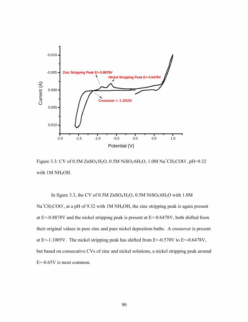
-2.0 -1.5 -1.0 -0.5 0.0 0.5 1.0
0.010
0.005
0.000
-0.005
-0.010
Nickel Stripping Peak E=-0.6478VZinc Stripping Peak E=-0.8878V
Cur
rent
(A)
Potential (V)
Crossover = -1.1013V
Figure 3.3: CV of 0.5M ZnSO4.H2O, 0.5M NiSO4
.6H2O, 1.0M Na+CH3COO-, pH=9.32
with 1M NH4OH.
In figure 3.3, the CV of 0.5M ZnSO4.H2O, 0.5M NiSO4
.6H2O with 1.0M
Na+CH3COO-, at a pH of 9.32 with 1M NH4OH, the zinc stripping peak is again present
at E=-0.8878V and the nickel stripping peak is present at E=-0.6478V, both shifted from
their original values in pure zinc and pure nickel deposition baths. A crossover is present
at E=-1.1005V. The nickel stripping peak has shifted from E=-0.570V to E=-0.6478V,
but based on consecutive CVs of zinc and nickel solutions, a nickel stripping peak around
E=-0.65V is most common.
90
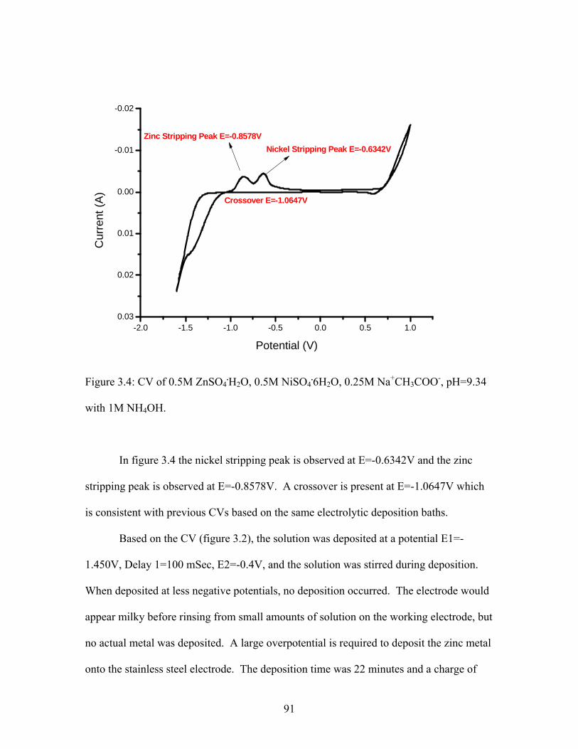
-2.0 -1.5 -1.0 -0.5 0.0 0.5 1.00.03
0.02
0.01
0.00
-0.01
-0.02
Nickel Stripping Peak E=-0.6342VZinc Stripping Peak E=-0.8578V
Crossover E=-1.0647V
Cur
rent
(A)
Potential (V)
Figure 3.4: CV of 0.5M ZnSO4.H2O, 0.5M NiSO4
.6H2O, 0.25M Na+CH3COO-, pH=9.34
with 1M NH4OH.
In figure 3.4 the nickel stripping peak is observed at E=-0.6342V and the zinc
stripping peak is observed at E=-0.8578V. A crossover is present at E=-1.0647V which
is consistent with previous CVs based on the same electrolytic deposition baths.
Based on the CV (figure 3.2), the solution was deposited at a potential E1=-
1.450V, Delay 1=100 mSec, E2=-0.4V, and the solution was stirred during deposition.
When deposited at less negative potentials, no deposition occurred. The electrode would
appear milky before rinsing from small amounts of solution on the working electrode, but
no actual metal was deposited. A large overpotential is required to deposit the zinc metal
onto the stainless steel electrode. The deposition time was 22 minutes and a charge of
91

+21.55C was passed with current ranging from +21.60mA at the beginning of the
deposition to +12.34mA at the end of deposition.
40 60 80 1000
200
Inte
nsity
(CP
S)
2 Theta (degrees)
43.5
Zn
101
44.5
SS
110
64.7
SS
200
82.1
SS
211
Figure 3.5: XRD pattern of plating from 0.5M ZnSO4.H2O, 0.5M NiSO4
.6H2O, 0.25M
Na+CH3COO-, pH=9.34 with 1M NH4OH.
Based on this XRD pattern (figure 3.5), it is clear the zinc is being preferentially
deposited (the 101 plane, pdf 04-0831) but the gamma phase alloy is not present. In
alkaline solutions the gamma phase preferentially deposits as the 330 plane which has a
reflection at 2θ=42.88◦ which is not observed in this x-ray pattern. A 2:1 zinc-nickel
molar ratio was also examined as a possible plating solution, which contained 0.25M Ni,
0.5M Zn, 0.25M acetate with 1M NH4OH, pH=9.3. Based on previous data this solution
was deposited at a potential of E=1.5V for 34 minutes with a total charge of +12.03C
92

being passed. The electrode appeared to have a dull metal plated onto it. Based on the
XRD pattern (figure 3.6), zinc metal is present in the deposit and small amounts of
gamma phase represented by the peaks at 2θ=62.4◦ (600 reflection) and 2θ=78.5◦ (552
reflection). When pure gamma phase is obtained from an alkaline bath, gamma phase is
preferentially deposited as the 330 reflection, as confirmed in my later work.
20 30 40 50 60 70 80 90 100 110
0
200
400
600
800
1000
1200
Inte
nsity
(CP
S)
2 Theta (degrees)
36.6
Zn
002
43 Z
n 10
144
.8 S
S 11
0
62.4
Gam
ma
Phas
e 60
065
.1 S
S 20
0
78.5
Gam
ma
Phas
e 55
282
.2 S
S 21
1
Figure 3.6: XRD pattern from 0.5M ZnSO4.H2O, 0.25M NiSO4
.6H2O, 0.25M
Na+CH3COO-, pH=9.3 with 1M NH4OH.
In figure 3.6 small amounts of gamma phase are present among a strong zinc
deposition present on the electrode. The gamma phase peaks are shifted from the
93

expected values by +0.142 degrees for the 600 reflection and -0.188 degrees for the 552
reflection.
The solution must be adjusted to allow for maximum gamma phase deposition.
Zinc and nickel salts with an acetate complexing ligand were dissolved and brought to a
pH of 9.3 with 1M ammonium hydroxide separately, then combined for deposition.
-2 -1 0 10.010
0.008
0.006
0.004
0.002
0.000
-0.002
-0.004
-0.006
-0.008
-0.010
Cur
rent
(A)
Potential (V)
Zinc Stripping Peak E=-0.878V
Nickel Stripping Peak E=-0.648V
Crossover E=-1.12V
Figure 3.7: CV of 0.5M ZnSO4.H2O, 0.5M NiSO4
.6H2O, 0.5M Na+CH3COO-, pH=9.32
with 1M NH4OH.
In the CV (figure 3.7) there are 2 separate stripping peaks present, E=-0.648V,
corresponding to nickel metal stripping off the electrode, and E=-0.878V, corresponding
to zinc metal stripping off the electrode, with a crossover present at E=-1.12V. The
94

crossover gives an indication of where nucleation sites begin to appear on the substrate.
Based on this CV, the solution was plated at E1=E3=-1.4V, E2=-1.0V and delay 1=delay
2=1 sec. The deposition lasted 3 hours 45 minutes and +20.04C of charge was passed.
The current ranged from +0.4780 mA to 5.906mA. No metal was present on the
electrode after the deposition.
Zinc sulfate monohydrate and nickel ammonium sulfate hexahydrate were
examined in equal molar concentrations.
-1.5 -1.0 -0.5 0.0 0.5 1.00.08
0.06
0.04
0.02
0.00
-0.02
Cur
rent
(A)
Potential (V)
Nickel Stripping Peak E=-0.62V
E=+0.142V
Crossover E=-1.112VCrossover E=-1.28V
Zinc Stripping Peak E=-0.9178V
Figure 3.8: CV of 0.5M ZnSO4.H2O, 0.5M Ni(NH4)2(SO4)2
.6H2O, 0.5M Na+CH3COO-,
pH=9.3 with 1M NH4OH.
In figure 3.8, the CV shows a metal stripping peak at E=--0.936V which is
believed to be due to zinc metal, a stripping peak at E=-0.62 which is believed to be due
to nickel metal and a small stripping peak at E=+0.142V whose source is unknown.
95

There are 2 crossovers present at E=-1.112V and E=-1.28V. The solution was deposited
at E1= E2 =-1.350V, E2=-0.400V, delay 1=delay 2= 1 sec, and the solution was stirred
throughout the deposition. A total of +13.00C of charge was passed, with the current
ranging from +10.28mA to 11.93mA. The deposition lasted 23 minutes.
20 30 40 50 60 70 80 90 100 110
0
100
200
300
400
500
600
Inte
nsity
(CP
S)
2 Theta (degrees)
35.1
Zn
002
43.1
Zn
101
44.6
SS
110
62.6
Gam
ma
Phas
e 60
064
.8 S
S 20
0
73.7
Gam
ma
Phas
e 44
4
79 G
amm
a Ph
ase
552
82.1
SS
211
98.7
SS
220
Figure 3.9: XRD pattern from solution of 0.5M ZnSO4.H2O, 0.5M Ni(NH4)2(SO4)2
.6H2O,
0.5M Na+CH3COO-, pH=9.3 with 1M NH4OH.
Figure 3.9 shows there is again strong zinc deposition present on the electrode
with small amounts of gamma phase being deposited with the zinc metal. The gamma
phase peaks are again shifted from the expected values by 0.342 degrees for the 600
reflection, 0.439 degrees for the 444 reflection and 0.312 degrees for the 552 reflection.
96

3.3 Chronocoulometry
Based on the pure zinc and nickel depositions from baths containing both metals,
chronocoulometry was employed to determine the diffusion coefficients of zinc and
nickel metals in the electrolytic baths, to better determine the zinc:nickel ratio needed for
alloy deposition to occur. Chronocoulometry (CC) is a technique where a potential step
is applied to the system and the charge is measured versus time.
Figure 3.10: Chronocoulometry diagram.
97

CC can be used to accurately determine the kinetic rate constant of a depositing
species. The Cottrell equation is used to determine the diffusion coefficient of the
absorbing species.
i=(nFAC0D01/2)/(π1/2t) Eq. 3.1
Where: i= Current, A n= Number of electrons transferred A= Area of electrode, cm2 C0= Concentration of species of interest, mol/cm3 D0= Diffusion Coefficient, cm2/sec t= time, seconds
When integrated, the Cottrell equation can be plotted as the Anson plot, with the charge
(Q) as a function of t½.
Figure 3.11: Anson plot diagram.
98

The electrode area can be measured physically or electrochemically.
Electrochemical area can differ from physical area of an electrode dependent on the
roughness of the electrode surface. To determine electrode area, a chronocoulometry
experiment is performed on ferricyanide, which has a known diffusion coefficient of 7.6
x 10-6 cm2/sec. For ferricyande, n is 1, because one electrode is transferred. The
concentration used in the experiments was 1.1 x 10⁻⁶ mol/cm3. The electrochemically
active area was determined to be 0.80 ± 0.18 cm2. The physical area of the electrode was
0.7932cm2.
The diffusion coefficients of zinc and nickel in alkaline solution with acetate
ligand were determined to be 2.86 x 10⁻⁴ ± 8.33 x 10⁻⁵ for nickel and 1.13 x 10⁻⁴ ± 6.73 x
10-5 for zinc. The diffusion coefficient for nickel is slightly larger than the diffusion
coefficient of zinc, demonstrating the nickel concentration might need to be controlled in
this solution. Dependent upon the solution used the diffusion coefficient data can be used
to determine the optimal concentrations in the bath.
3.4 Linear Sweep Voltammetry
Linear sweep voltammetry (LSV) is a technique used to determine the deposition
current of species in solution, and the effects of secondary metals in a solution can be
examined. In LSV the electrode potential is varied at a constant rate.
99

-1.5 -1.0 -0.50.04
0.03
0.02
0.01
0.00
Cur
rent
(A)
Potential (V)
Nickel
Zinc Zinc-Nickel Alloy
Figure 3.12: LSV of zinc, nickel and zinc-nickel alloy.
Figure 3.12 is the linear sweep voltammetry plot of zinc, nickel and zinc-nickel
combined as a plot of the current versus potential. All solutions were swept from
potentials of E=-1.5V to open circuit potential (OCP, E=+0.060V). Individually zinc has
an anodic stripping peak present at E=-1.1052V and nickel has an anodic stripping peak
present at E=-0.4804V. When combined in solution, the zinc and nickel anodic stripping
peaks are clearly shifted from the original values. In the combined solution the zinc
anodic stripping peak is present at E-=0.679V and the nickel stripping peak is present at
E=-0.5444V. Clearly the anodic stripping potentials of the zinc and nickel metals have
100

been shifted in the combined solution, showing the metals affect the deposition of one
another when combined.
3.5 Atomic Absorption Analysis
The depositions of interest were examined with atomic absorption spectroscopy
(AAS) to determine the zinc and nickel percentages present in the deposited films. The
film deposit was dissolved in 20mL of a 3M HNO3 solution, and once dissolved diluted
to 100 mL with DI H2O. One mL of this diluted metal solution was diluted to 50 mL of
solution with DI H2O, to make an appropriate concentration range for atomic absorption
analysis. A standard addition method was used to determine the concentrations of the
metals. In AAS interfering species can cause false measurements or mask ions of
interest, and since both zinc and nickel were present a standard addition method was used
to obtain more accurate results.
3.6 Alkaline Metal Deposition from Aqueous Solution with Acetate Ligand
Acetate was able to efficiently complex both zinc and nickel in their respective
solutions so this was examined as a ligand for both zinc and nickel present in the same
solution. The acetate concentration was minimized in most deposition solutions to a one
molar equivalent to the metal in solution because ammonia should also be complexing
the metals in solution, acetate just adds the added stabilization needed to keep the metals
in solution in time to deposit. All solutions were stirred during deposition to keep the
zinc sulfate monohydrate and the nickel sulfate hexahydrate in solution.
101

3.6.1 Zinc Sulfate Monohydrate and Nickel Sulfate Hexahydrate
Zinc sulfate monohydrate and nickel sulfate hexahydrate with acetate as a
complexing ligand was examined in an aqueous solution for the deposition of zinc-nickel
alloys films. The general solution composition was the following:
ZnSO4.H2O + NiSO4
.6H2O + Na+CH3COO- + 1M NH4OH
3.6.1.1 Zinc-Nickel 1:1 Molar Ratio
The first ratio examined was a 1 to 1 molar equivalent of zinc to nickel in solution.
The diffusion coefficients of zinc and nickel were fairly close, with nickel being slightly
larger than zinc so a 1:1 molar ratio was examined. The molar ratios examined for zinc
sulfate monohydrate and nickel sulfate monohydrate were 0.1M ZnSO4.H2O, 0.1M
NiSO4.6H2O, 0.1M Na+CH3COO- and a pH of 9.39 with 1M NH4OH.
102

-2 -1 0 10.02
0.00
Cur
rent
(A)
Potential (V)
Nickel Stripping Peak E=-0.4194V
Crossover E=-0.9485V
Figure 3.13: CV of 1:1 ratio of zinc-nickel, with acetate, pH=9.39 with 1M NH4OH.
In the CV (figure 3.13) there is only one stripping peak present at E=-0.4194V,
which is due to nickel metal being stripped off the electrode. There is a crossover at E=-
0.9485V. This solution was plated based on this CV with a potential step method under
the following parameters: E1= -1.1V, E=-0.66V, delay 1=60.0 sec, delay 2=15.0 sec.
The deposition time was one hour 13 minutes and a total of +18.23C was passed. A
strong metal deposition was observed on the electrode so this was x-rayed for
confirmation.
103

35 40 45 50 55 60 65 70 75 80 85 90 95 1000
500
Inte
nsity
(CPS
)
2 Theta (Degrees)
44.4
56 N
i 111
Pea
k
51.7
49 N
i 200
Pea
k
76.0
05 N
i 220
Pea
k
92.9
90 N
i 311
Pea
k
98.4
03 N
i 222
Pea
k
Figure 3.14: XRD pattern, 1:1 Zn-Ni ratio with acetate ligand, pH=9.3 with 1M NH4OH.
It is clear from figure 3.14, the XRD pattern of the plating that only nickel is
present on the electrode. The nickel has been deposited in a random fashion, confirmed
by PDF#04-0850 (JCPDS Database).
Based on this XRD pattern, it was clear the nickel concentration in the bath
needed to be controlled, so deposition baths were altered accordingly.
3.6.1.2 Zinc-Nickel 3:1 and 4:1 Molar Ratios
A deposition bath containing 0.3M ZnSO4.H2O, 0.1M NiSO4
.6H2O, and 0.1M
Na+CH3COO- was examined. In the chronocoulometry results, nickel demonstrated a
slight preference to zinc to diffuse to the electrode surface, so based on this data and
previous deposits, the nickel concentration was lowered in the electrochemical bath. The
104

pH of this solution was 9.37 with 1M NH4OH. The CV of this solution is shown in
figure 3.15.
-1.5 -1.0 -0.5 0.00.030
0.025
0.020
0.015
0.010
0.005
0.000
-0.005
-0.010
Potential (V)
Zinc Stripping Peak E=-0.9574VNickel Stripping Peak E=-0.5823V
Cur
rent
(A)
Figure 3.15: 3:1 molar ratio of ZnSO4.H2O, NiSO4
.6H2O, pH=9.37 with 1M NH4OH
Based on this CV (figure 3.15) the deposition was performed with a potential step
method under these conditions: E1=-1.37V, E2=-1.00V, delay 1=60.0 sec, delay 2=20.0
sec. A total of +38.73C was passed. A small amount of metal deposition was observed
and was x-rayed for confirmation.
105

30 35 40 45 50 55 60 65 70 75 80 85 90 95 100 1050
100
200
300
400
500In
tens
ity (C
PS
)
2 Theta (Degrees)
42.9
53 G
amm
a ph
ase
330
peak
44.6
59 S
tain
less
Ste
el 1
10 P
eak
64.8
57 S
tain
less
Ste
el 2
00 P
eak
82.3
93 S
tain
less
Ste
el 2
11 P
eak
Figure 3.16: XRD pattern of gamma phase alloy deposited from 2:1 ZnSO4.H2O,
Ni(NH4)2(SO4)2.6H2O, pH adjusted with 1M NH4OH.
The XRD pattern (figure 3.16) confirms the presence of gamma phase Zn-Ni
preferentially deposited to the 330 plane (per pdf #06-0653). Previously, pure gamma
phase was not obtained, zinc metal deposition with gamma phase contamination was
observed. In this pattern, the gamma phase is preferentially deposited as the gamma 330
reflection which is expected in alkaline solution.
Atomic absorption spectroscopy was used to determine the metal concentrations
in the deposit.
106

y = 1.698x + 0.1518R2 = 0.9845
-1
-0.5
0
0.5
1
1.5
-0.6 -0.4 -0.2 0 0.2 0.4 0.6 0.8
Volume standard added (ppm)
Abs
orba
nce
Figure 3.17: AAS standard addition method- zinc concentration determination.
y = 0.3977x + 0.0073R2 = 0.9971
-0.5
-0.4
-0.3
-0.2
-0.1
0
0.1
0.2
0.3
0.4
-1.5 -1 -0.5 0 0.5 1
Volume Standard Nickel Added (ppm)
Abs
orba
nce
Figure 3.18: AAS standard addition method- nickel concentration determination.
107

The metal concentration in the deposit was back calculated based on the results
obtained from the following equation for standard addition method:
Eq. 3.1
The alloy was composed of 83% zinc and 17% nickel. The nickel percentage in
the deposit is a little high compared to what has been found to offer the best corrosion
resistance, so a deposition bath with a slightly higher zinc concentration was examined.
A deposition bath containing 0.4M ZnSO4.H2O, 0.1M NiSO4
.6H2O and 0.4 M
Na+CH3COO- was examined. The pH of this solution was 9.35 with 1M NH4OH. The
deposition was performed with a potential step method under these conditions: E1=-
1.37V, E2=-1.00V, delay 1=60.0 sec, delay 2=20.0 sec. A total of +27.86C was passed
in 41 minutes. A strong metal deposition was observed and was x-rayed for
confirmation.
108

35 40 45 50 55 60 65 70 75 80 85 90 95 100
100
200
300
Inte
nsity
(CPS
)
A
42.9
03 G
amm
a Ph
ase
330
Figure 3.19: XRD pattern 4:1 ratio zinc to nickel.
Figure 3.19 shows a deposition of gamma phase zinc-nickel alloy being
preferentially deposited as the gamma 330 plane (per pdf #06-0653- JCPDS Database).
The deposit was analyzed with AAS and the zinc concentration in the deposit was 92.4%
and the nickel concentration was 7.6%, which is in the range of interest for maximized
corrosion protection (8-15%).
3.6.2 Zinc Sulfate Monohydrate and Nickel Ammonium Sulfate Hexahydrate
Zinc sulfate monohydrate and nickel ammonium sulfate hexahydrate with acetate as a
complexing ligand for the zinc in solution was examined in an aqueous phase for the
deposition of zinc-nickel alloys films. The general solution composition was the
following:
109

ZnSO4.H2O + Ni(NH4)2(SO4)2
.6H2O + Na+CH3COO- + 1M NH4OH
3.6.2.1 Zinc-Nickel 2:1 Molar Ratio
The first ratio examined was a 2:1 molar equivalent of zinc to nickel in solution. The
molar ratios examined for zinc sulfate monohydrate and nickel sulfate monohydrate were
0.2M ZnSO4.H2O, 0.1M Ni(NH4)2(SO4)2
.6H2O, 0.1M Na+CH3COO- and a pH of 9.36
with 1M NH4OH.
This solution was plated based on previous deposition data with a potential step
method under the following parameters: E1= -1.45V, E=-0.V, delay 1=60.0 sec, delay
2=20.0 sec. The deposition time was 36 minutes and a total of +14.80C was passed. A
strong metal deposition was observed on the electrode so this was x-rayed for
confirmation. Based on previous gamma phase deposition XRD patterns, it was clear the
gamma phase preferentially deposits to the 330 plane so the sample was measured in a 2θ
range value of 35 to 50 degrees.
40 45 50
200
400
600
800
Inte
nsity
(CP
S)
2 Theta (D egrees)
42.8
95 G
amm
a Ph
ase
330
Figure 3.20: XRD pattern, 1:1 Zn-Ni ratio with acetate ligand, pH=9.3 with 1M NH4OH.
110
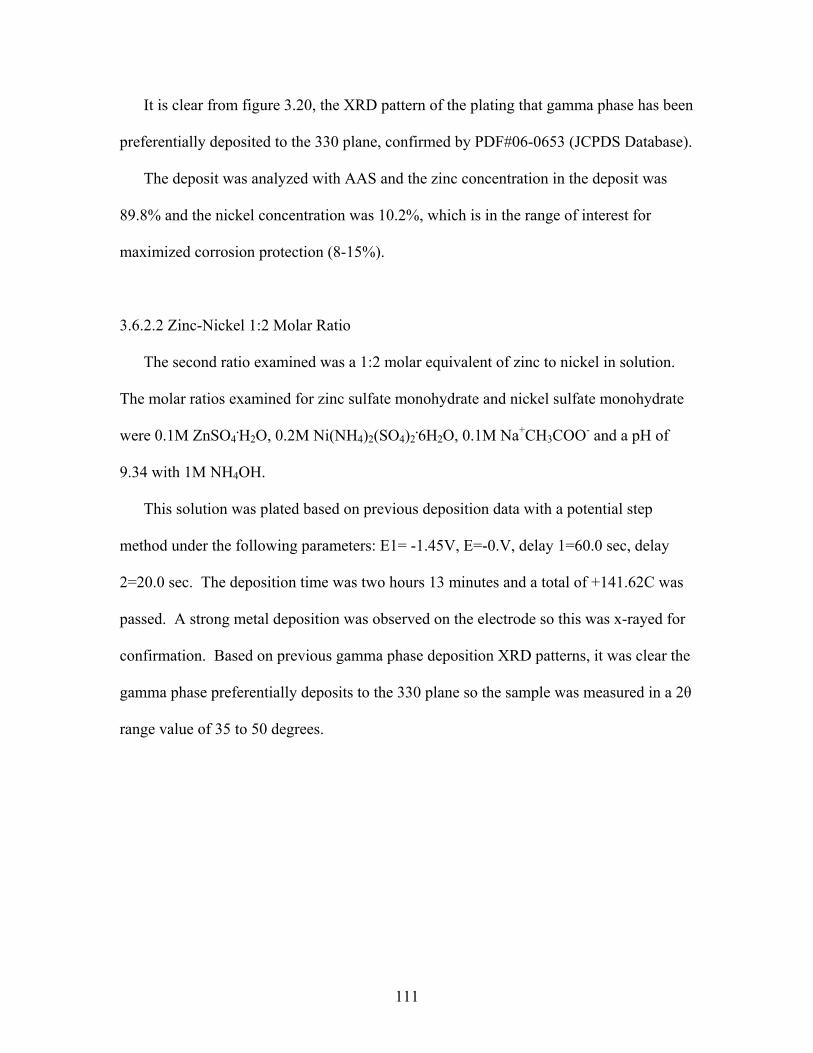
It is clear from figure 3.20, the XRD pattern of the plating that gamma phase has been
preferentially deposited to the 330 plane, confirmed by PDF#06-0653 (JCPDS Database).
The deposit was analyzed with AAS and the zinc concentration in the deposit was
89.8% and the nickel concentration was 10.2%, which is in the range of interest for
maximized corrosion protection (8-15%).
3.6.2.2 Zinc-Nickel 1:2 Molar Ratio
The second ratio examined was a 1:2 molar equivalent of zinc to nickel in solution.
The molar ratios examined for zinc sulfate monohydrate and nickel sulfate monohydrate
were 0.1M ZnSO4.H2O, 0.2M Ni(NH4)2(SO4)2
.6H2O, 0.1M Na+CH3COO- and a pH of
9.34 with 1M NH4OH.
This solution was plated based on previous deposition data with a potential step
method under the following parameters: E1= -1.45V, E=-0.V, delay 1=60.0 sec, delay
2=20.0 sec. The deposition time was two hours 13 minutes and a total of +141.62C was
passed. A strong metal deposition was observed on the electrode so this was x-rayed for
confirmation. Based on previous gamma phase deposition XRD patterns, it was clear the
gamma phase preferentially deposits to the 330 plane so the sample was measured in a 2θ
range value of 35 to 50 degrees.
111

35 40 45 50
100
200
300
Inte
nsity
(CP
S)
2 Theta(Degrees)
42.9
03 G
amm
a Ph
ase
330
Figure 3.21: XRD pattern, 1:1 Zn-Ni ratio with acetate ligand, pH=9.3 with 1M NH4OH.
It is clear from figure 3.21 the XRD pattern of the plating that gamma phase has
been preferentially deposited to the 330 plane, confirmed by PDF#06-0653 (JCPDS
Database).
The deposit was analyzed with AAS and the zinc concentration in the deposit was
74.5% and the nickel concentration was 25.5%, which is outside in the range of interest
for maximized corrosion protection (8-15%). There is too much nickel present in the
deposit, so the controlled nickel concentration of a 2:1 zinc nickel ratio in the bath is
needed for the correct metal percentage in the depositing film.
112
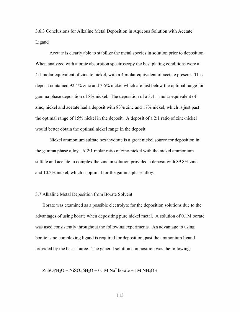
3.6.3 Conclusions for Alkaline Metal Deposition in Aqueous Solution with Acetate
Ligand
Acetate is clearly able to stabilize the metal species in solution prior to deposition.
When analyzed with atomic absorption spectroscopy the best plating conditions were a
4:1 molar equivalent of zinc to nickel, with a 4 molar equivalent of acetate present. This
deposit contained 92.4% zinc and 7.6% nickel which are just below the optimal range for
gamma phase deposition of 8% nickel. The deposition of a 3:1:1 molar equivalent of
zinc, nickel and acetate had a deposit with 83% zinc and 17% nickel, which is just past
the optimal range of 15% nickel in the deposit. A deposit of a 2:1 ratio of zinc-nickel
would better obtain the optimal nickel range in the deposit.
Nickel ammonium sulfate hexahydrate is a great nickel source for deposition in
the gamma phase alloy. A 2:1 molar ratio of zinc-nickel with the nickel ammonium
sulfate and acetate to complex the zinc in solution provided a deposit with 89.8% zinc
and 10.2% nickel, which is optimal for the gamma phase alloy.
3.7 Alkaline Metal Deposition from Borate Solvent
Borate was examined as a possible electrolyte for the deposition solutions due to the
advantages of using borate when depositing pure nickel metal. A solution of 0.1M borate
was used consistently throughout the following experiments. An advantage to using
borate is no complexing ligand is required for deposition, past the ammonium ligand
provided by the base source. The general solution composition was the following:
ZnSO4.H2O + NiSO4
.6H2O + 0.1M Na+ borate + 1M NH4OH
113

3.7.1 Zinc Sulfate Monohydrate and Nickel Sulfate Hexahydrate
Zinc sulfate monohydrate and nickel sulfate hexahydrate with 0.1M borate solution as
the aqueous phase was examined for the deposition of zinc-nickel alloys films. The
general solution composition was the following:
ZnSO4.H2O + NiSO4
.6H2O + Na+ borate + 1M NH4OH
3.7.1.1 Zinc Nickel in a 1:1 Molar Ratio
The first ratio examined was a 1 to 1 molar equivalent of zinc to nickel in solution.
The molar ratios examined for zinc sulfate monohydrate and nickel sulfate monohydrate
were 0.1M ZnSO4.H2O, 0.1M NiSO4
.6H2O, 0.1M borate and a pH of 9.41 with 1M
NH4OH.
-2 -1 0 1
0.016
0.014
0.012
0.010
0.008
0.006
0.004
0.002
0.000
-0.002
Cur
rent
(A)
Potential (V)
Zinc Stripping Peak E=-0.8129V
Crossover E=-1.084V
Figure 3.22: CV of 0.1M ZnSO4.H2O, 0.1M NiSO4
.6H2O, 0.1M borate and a pH of 9.41
with 1M NH4OH.
114
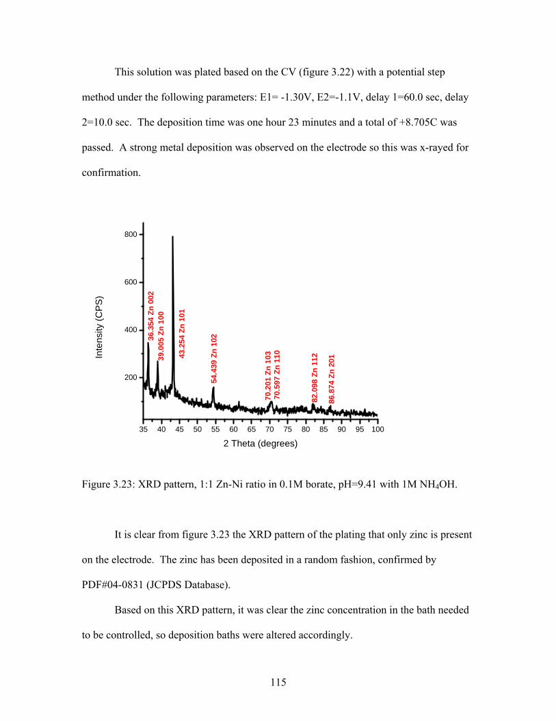
This solution was plated based on the CV (figure 3.22) with a potential step
method under the following parameters: E1= -1.30V, E2=-1.1V, delay 1=60.0 sec, delay
2=10.0 sec. The deposition time was one hour 23 minutes and a total of +8.705C was
passed. A strong metal deposition was observed on the electrode so this was x-rayed for
confirmation.
35 40 45 50 55 60 65 70 75 80 85 90 95 100
200
400
600
800
Inte
nsity
(CPS
)
2 Theta (degrees)
36.3
54 Z
n 00
239
.005
Zn
100
43.2
54 Z
n 10
1
54.4
39 Z
n 10
2
70.2
01 Z
n 10
370
.597
Zn
110
82.0
98 Z
n 11
2
86.8
74 Z
n 20
1
Figure 3.23: XRD pattern, 1:1 Zn-Ni ratio in 0.1M borate, pH=9.41 with 1M NH4OH.
It is clear from figure 3.23 the XRD pattern of the plating that only zinc is present
on the electrode. The zinc has been deposited in a random fashion, confirmed by
PDF#04-0831 (JCPDS Database).
Based on this XRD pattern, it was clear the zinc concentration in the bath needed
to be controlled, so deposition baths were altered accordingly.
115

3.7.1.2 Zinc and Nickel in a 1:3 Molar Ratio
The second ratio examined was a 1 to 3 molar equivalent of zinc to nickel in
solution. The molar ratios examined for zinc sulfate monohydrate and nickel sulfate
monohydrate were 0.1M ZnSO4.H2O, 0.3M NiSO4
.6H2O, 0.1M borate and a pH of 9.35
with 1M NH4OH. This solution was plated based on previous deposition data with a
potential step method under the following parameters: E1= -1.37V, E2=-1.0V, delay
1=60.0 sec, delay 2=20.0 sec. The deposition time was 21 minutes and a total of
+34.18C were passed. A strong metal deposition was observed on the electrode so this
was x-rayed for confirmation.
35 40 45 50 55 60 65 70 75 80 85 90 95 100
200
400
Inte
nsity
(CPS
)
2 Theta (Degrees)
44.6
01 N
i 111
51.8
00 N
i 200
76.5
93 N
i 220
92.9
7 N
i 311
Figure 3.24: XRD pattern, 1:3 Zn-Ni ratio in 0.1M borate, pH=9.41 with 1M NH4OH.
116

It is clear from figure 3.24, the XRD pattern of the plating that only nickel is
present on the electrode. The nickel has been deposited in a random fashion, confirmed
by PDF#04-0850 (JCPDS Database).
Based on this XRD pattern, it was clear both the zinc and nickel concentrations in
the bath needed to be carefully controlled.
3.7.2 Zinc Sulfate Monohydrate and Nickel Ammonium Sulfate Hexahydrate in Borate
Nickel ammonium sulfate hexahydrate was also examined as a nickel source for
gamma phase alloy deposition in borate solutions. The general solution composition was
the following:
ZnSO4.H2O + Ni(NH4)2(SO4)2
.6H2O + 1M NH4OH
3.7.2.1 Zinc-Nickel 1:1 Molar Ratio
The first ratio examined was a 1:1 molar equivalent of zinc to nickel in solution. The
molar ratios examined for zinc sulfate monohydrate and nickel ammonium sulfate
hexahydrate were 0.2M ZnSO4.H2O, 0.1M Ni(NH4)2(SO4)2
.6H2O and a pH of 9.35 with
1M NH4OH.
This solution was plated based on previous deposition data with a potential step
method under the following parameters: E1= -1.45V, E=-1.30V, delay 1=60.0 sec, delay
2=20.0 sec. The deposition time was 52 minutes and a total of +21.49C was passed. A
strong metal deposition was observed on the electrode so this was x-rayed for
confirmation.
117
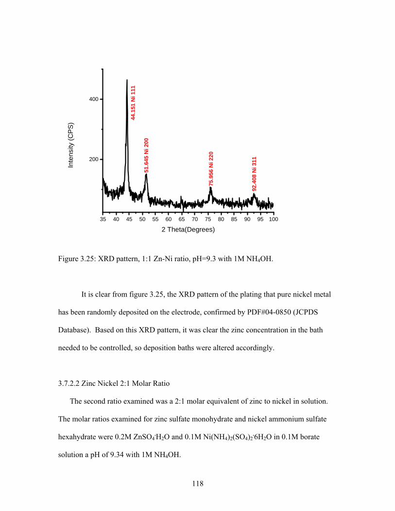
35 40 45 50 55 60 65 70 75 80 85 90 95 100
200
400
Inte
nsity
(CPS
)
2 Theta(Degrees)
44.1
51 N
i 111
51.6
45 N
i 200
75.9
56 N
i 220
92.4
08 N
i 311
Figure 3.25: XRD pattern, 1:1 Zn-Ni ratio, pH=9.3 with 1M NH4OH.
It is clear from figure 3.25, the XRD pattern of the plating that pure nickel metal
has been randomly deposited on the electrode, confirmed by PDF#04-0850 (JCPDS
Database). Based on this XRD pattern, it was clear the zinc concentration in the bath
needed to be controlled, so deposition baths were altered accordingly.
3.7.2.2 Zinc Nickel 2:1 Molar Ratio
The second ratio examined was a 2:1 molar equivalent of zinc to nickel in solution.
The molar ratios examined for zinc sulfate monohydrate and nickel ammonium sulfate
hexahydrate were 0.2M ZnSO4.H2O and 0.1M Ni(NH4)2(SO4)2
.6H2O in 0.1M borate
solution a pH of 9.34 with 1M NH4OH.
118

This solution was plated based on previous deposition data with a potential step
method under the following parameters: E1= -1.45V, E=-0.V, delay 1=60.0 sec, delay
2=20.0 sec. The deposition time was 52 minutes and a total of +21.43C was passed. A
strong metal deposition was observed on the electrode so this was x-rayed for
confirmation.
35 40 45 50 55 60 65 70 75 80 85 90 95 100
100
200
Inte
nsity
(CP
S)
2 Theta (Degrees)
43.9
01 G
amm
a Ph
ase
330
Figure 3.26: XRD pattern, 2:1 Zn-Ni ratio in 0.1M borate, pH=9.3 with 1M NH4OH.
It is clear from figure 3.26, the XRD pattern of the plating that gamma phase has
been preferentially deposited as the 330 plane, confirmed by PDF#06-0653 (JCPDS
Database).
119
The deposit was analyzed with AAS and the zinc concentration in the deposit was
84.4% and the nickel concentration was 15.6%, which is in the range of interest for
maximized corrosion protection (8-15%).
3.7.3 Conclusions for Alkaline Metal Deposition from Borate Solution
Borate solutions can be used to deposit out the pure metals from solution but did
not demonstrate as well for deposition of the gamma phase alloy. When using nickel
sulfate hexahydrate with zinc a 1:1 equivalent of zinc-nickel resulted in a deposit of pure
zinc metal. When the nickel concentration was increased in the plating solution the result
was a deposit of pure nickel metal.
When using nickel ammonium sulfate hexahydrate as the nickel source with a 1:1
ratio of zinc-nickel only nickel was deposited out of solution. When a 2:1 ratio of zinc-
nickel was used, a gamma phase deposit was obtained, and upon analysis with atomic
absorption spectroscopy the deposit was 84.4% zinc and 15.6% nickel, which is in the
optimal range for gamma phase deposition.
From borate solutions, when nickel ammonium sulfate hexahydrate is used as the
nickel source, gamma phase alloys can be easily deposited in the ratios desired for
optimal corrosion protection.
3.8 Conclusions for Zinc-Nickel Co-Deposition in Alkaline Solutions
Ammonium hydroxide was found to be the optimal base source for this work. A
working pH of 9.3-9.4 was used throughout the depositions. The zinc-nickel alloy
requires a large over potential to deposit onto the stainless steel electrode. A plating at or
120
around the crossover which is present in the CV was optimal for the metal to plate.
Below the crossover point, no deposition was observed. Sodium acetate was found to be
an optimal complexing ligand for both nickel and zinc in alkaline solution.
Borate was found to be extremely useful in this deposition when using nickel
ammonium sulfate hexahydrate as the nickel source.
Ammonium hydroxide is used as the base source for this work and the ammonium
is able to complex the nickel and zinc in solution to stabilize the metal cations before
deposition, but working in alkaline solutions offers up an influx of hydroxide ions that
readily combine with the metal cations to form metal hydroxides. In aqueous solution,
there is not a lot to stabilize these metal cations, even with the compexing agent of
ammonium and the metals readily precipitated out of solution. With the addition of
borate, the metals remain in solution for extended periods of time, thereby making
deposition easier. Borate was used to deposit the pure zinc and nickel metals, but when
combined, a nickel source of nickel ammonium sulfate hexahydrate is best for use in
borate solutions, this will provide you with the optimal zinc and nickel percentages
needed for optimal protection by the gamma phase alloy. Pulse plating was also found
favorable in relation to borate solutions. When applying a constant potential the metal
deposits tended to adhere very weakly to the stainless steel substrate, causing many flakes
that fell into solution. When pulsed between 2 potentials, the deposit become much
stronger and was difficult to remove from the stainless steel substrate.
A potential step method was found to be optimal for deposition of the metal films.
With this method we are able to obtain smoother deposits in a shorter time frame, making
this method desirable for the wider scope of applications. A large overpotential is
121

required for deposition, and this causes the metal to precipitate onto the electrode
quickly, and often unevenly. At lower potentials no deposition is observed. With this
potential step method, we are able to obtain the deposits at the high overpotentials
required for deposition to occur, and the deposits are smooth and even over the electrode
substrate.
The gamma phase zinc-nickel alloy (Ni5Zn21) was readily deposited out of
alkaline solutions with a preferred orientation to the 330 reflection. Ammonium
hydroxide offers a base source that allows us to work in less caustic conditions while still
reaching the basic ranges needed for optimal deposition. In an aqueous solvent system,
acetate offers support as a complexing ligand to both zinc and nickel in solution, to keep
them from precipitating out as metal hydroxides. The acetate is able to keep the metal
ions in solution long enough for metal deposition to occur. Borate solutions also offer
gamma phase deposition, best with nickel ammonium sulfate hexahydrate as the nickel
source for deposition.
Based on atomic absorption data, there are 3 optimal baths for gamma phase
deposition. The ratio of 4:1:4 zinc, nickel sulfate hexahydrate and acetate with a zinc
percentage in the deposit of 92.4% and a nickel percentage of 7.56%. The ratio of 2:1:1
of zinc, nickel ammonium sulfate hexahydrate and acetate in solution had a zinc
percentage of 89.8% and a nickel percentage of 10.2%. In borate solutions, the optimal
deposit was obtained from a 2:1 ratio bath of zinc and nickel ammonium sulfate
hexahydrate with an overall zinc percentage of 84.4% and a nickel percentage of 15.6%
in the deposit.
122

It has been concluded that the zinc-nickel gamma phase alloy is readily deposited
from an aqueous solution with acetate, with the nickel concentration being controlled in
the bath. In borate solutions, the zinc-nickel gamma phase alloy is easily deposited if
using nickel ammonium sulfate hexahydrate as the nickel source in solution. Pulse
plating is the preferred method for all deposits because it offers better adhesion to the
substrate surface and a much smoother deposit.
Pure zinc and nickel metal films were easily deposited out of alkaline baths in the
pH=9.3 range. Acetate was found to be a good complexing ligand for both zinc and
nickel in alkaline baths with water as the aqueous phase; a borate solution as the aqueous
phase also provided quality films with nickel ammonium sulfate hexahydrate as the
nickel source.
3.9 Differences from Literature
In the literature, work has been performed at very caustic pH ranges of ≥12, with
very little work being performed in the pH range of 9.3-9.5. This work focuses on the pH
range of 9.3-9.4, which offers milder working conditions for the scale of industry.
Sodium acetate was found to be a good complexing ligand for both zinc and nickel ions
in solution, offering up quality gamma phase alloys without contamination often seen in
acidic baths. Previous work has required elevated working temperatures and this work
has been completed at room temperature, again lending to the simplicity of industrial
scale work.
The gamma phase alloy was readily deposited out of solution when using nickel
ammonium sulfate hexahydrate as the nickel source in a borate electrolytic solution,
123

which had not been examined previously. Nickel ammonium sulfate hexahydrate stays in
solution without the addition of a complexing ligand in alkaline conditions, and readily
deposits out as pure nickel metal, and as zinc-nickel gamma phase when in solution with
zinc.
The step potential method was also extremely useful in this work. With the step
potential method, one is able to obtain quality films that adhere very strongly to the
stainless steel electrode surface. Without this method the deposits readily came off of the
stainless steel electrode surface, both as metal flakes and as the whole deposit just being
removed. With this method, the deposit is very hard to remove from the stainless steel
electrode surface.
3.10 Future work
The next steps for this thesis work include obtaining scanning electron
microscope (SEM images) of the deposits to determine uniformity and grain structure. It
has been noted in the literature that more compact grains are preferred for optimal
corrosion resistance.
The acetate aqueous solution will be examined to determine how the acetate is
able to stabilize the metals in solution, along with ammonia being present due to
ammonium hydroxide being utilized as the base source.
Ammonia absorption on the electrode surface as a chemisorb will be examined, to
determine if this is playing a role in gamma phase deposition, and if this has an effect on
the gamma phase being preferentially deposited to the 330 reflection.
124

The borate electrolytic solution will be examined more extensively to determine if
the borate is complexing the metal ions in solution, and why an additional complexing
ligand is not required as in aqueous phase solutions.
Corrosion protection properties of these films will be studied using
electrochemical techniques.
125

REFERENCES
[1] Abou-Krisha, M. M., Applied Surface Science, 252, (2005), 1035-1048
[2] Gaevskaya, T.V.; Byk, T.V.; Tsybul’skaya, L.S., Russian Journal of Applied
Chemistry, 76, (2003), 1583-1588.
[3] Bajat, J.B.; Maksimovic, M.D.; Miskovic-Stankovic, V.B.; Zec, S., Journal of
Applied Electrochemistry, 31, (2001), 355-361.
[4] Zaki, N., Metal Finishing, 6, (1989), 57-60.
[5] Lee, H.Y.; Kim, S.G., Surface and Coatings Technology, 135, (2000), 69-74.
[6] Ganesan, P.; Kumaraguru, S.P.; Popov, B.N., Surface & Coatings Technology, 201,
(2006), 3658-3669.
[7] Wynn, P.C., Atotech UK Limited, United Kingdom,
www.atotech.com/data/publications/ZnNi_Electroplating_SurFin_2001.pdf
[8] Bates, J. A., Plating and Surface Finishing, 81, (1994), 36-44.
[9] Kim, H.; Popov, B. N.; Chen, K. S., Journal of the Electrochemical Society, 150,
(2003), C8i-C88.
[10] Petrauskas, A., Grinceviciene, L.; Cesuniene, A.; Matulionis, E., Surface & Coatings
Technology, 192, (2005), 299-304.
[11] Muller, C.; Sarret, M.; Benballa, M., Electrochimica Acta, 46, (2001), 2811-2817.
[12] Petrauskas, A.; Grinceviciene, L.; Cesuniene, A.; Juskenas, R., Electrochemica Acta,
50, (2005), 1189-1196.
[13] Roventi, G.; Fratesi, R.; Della Guardia, R.A.; Barucca, G., Journal of Applied
Electrochemistry, 30, (2000), 173-179.
126

[14] Abou-Krisha, M.M.; Assaf, F.H.; Toghan, A.A. J Solid State Electrochem, 11,
(2007), 244-252.
[15] Bajat, J. B.; Maksimovic, Miodrag D.; Radovic, Goran R., J. Serb. Chem. Soc, 67,
(2002), 625-634.
[16] Tang, P.T.; Watanabe, T.; Andersen, J.E.T.; Bech-Neilsen, G., Journal of Applied
Electrochemistry, 25, (1995), 347-352.
[17] El-Sherik, A.M.; Erb, U.; Page, J., Surface and Coatings Technology, 88, (1996), 70-
78.
[18] Bajat, J.B.; Kačarević-Popvić, Z.; Mišković-Stanković, V.B.; Maksimović, M.D.,
Progress in Organic Coatings, 39, (2000), 127-135.
[19] Lin, Y. P.; Selman, J. R., Journal of Electrochemical Society, 140, (1993), 1229-
1303.
[20] Bobrikova, I.G.; Kukoz, F.I.; Selivanov, V.N.; Kopin, A.V., Russian Journal of
Electrochemistry, 38, (2002), 1148-1151.
[21] Lehmberg, C. E.; Lewis, D. B.; Marshall, G. W., Surface and Coatings Technology,
192, (2005), 269-277.
[22] Ohtsuka, T.; Komori, A., Electrochimica Acta, 43, (1998), 3269-3276.
[23] El Hajjami, A.; Et. Al., Applied Surface Science, 254, (2007), 480-489.
[24] Elkhatabi, F.; Sarret, M.; Muller, C., Journal of Electroanalytical Chemistry, 404,
(1996), 45-53.
[25] Sun, F.; Et. Al., Electrochimica Acta, 54, (2009), 1578-1583.
[26] Fratesi, R.; Roventi, G., Surface and Coatings Technology, 82, (1996), 158-164.
[27] Bhavnagar, P.; Free, M.L., Surface & Coatings Technology, 200, (2006), 6083-6087.
127

128
[28] Bajat, J. B.; Petrovic, A. B.; Maksimovic, M. D., J. Serb. Chem. Soc., 70, (2005),
1427-1439.
[29] Michael, M.S.; Radhakrishna, S., Anti-Corrosion Methods and Materials, 45,
(1998), 113-119.
[30] Elkhatabi, F.; Benballa, M.; Sarret, M.; Muller, C., Electrochimica Acta, 44, (1999),
1645-1653.
[31] Jiang, Y.F.; Et. Al., Thin Solid Films, 484, (2005), 232-237.
[32] Pfiz, R.; Strube, G., Transactions of the Institute of Metal Finishing, 74, (1996), 158-
160.
[33] Bharathi, S. R.; Vasudevan, T., Transactions of the Institute of Metal Finishing, 74,
(2000), 129-133.
[34] Tsybulskaya, L.S.; Gaevskaya, T.V., Purovskaya, O.G., Byk, T.V., Surface and
Coatings Technology, 103, (2008), 234-239.
[35] Hubert, C.; Naghavi, N.; Canava, B.; Etcheberry, A.; Lincot, D., Thin Solid Films,
515, (2007), 6023-6035.
[36] Chandrasekar, M.S.; Srinivasan, S.; Pushpavanam, M., Journal of Solid State
Electrochemistry, 13, (2009), 781-789.