Embed Size (px)
Citation preview

九州大学学術情報リポジトリKyushu University Institutional Repository
Electrochemical and Theoretical Studies onNickel Dithiolene Hydrogen Evolution Catalysts:Developing Ligand-based Proton-coupled ElectronTransfer Pathways
小柴, 慧太
http://hdl.handle.net/2324/2236028
出版情報:九州大学, 2018, 博士(理学), 課程博士バージョン:権利関係:

Electrochemical and Theoretical Studies on
Nickel Dithiolene
Hydrogen Evolution Catalysts:
Developing Ligand-based
Proton-coupled Electron Transfer Pathways
Keita Koshiba
March 2019
Department of Chemistry
Graduate School of Science
Kyushu University


Contents
General Introduction 1
Hydrogen Evolution Reaction (HER) 1
HER in Nature: [NiFe] and [FeFe] hydrogenases 2
Molecular Catalysis for Electrochemical HER 5
Ligand-based PCET Reduction for HER 10
HER Catalyzed by Bis(dithiolene) Complexes 15
Mechanism of HER Catalyzed by Bis(dithiolene) Complexes 16
Survey of This Thesis 19
References 20
Chapter 1: A Nickel Dithiolate Water Reduction Catalyst Providing Ligand-based
Proton-coupled Electron Transfer Pathways 23
Introduction 23
Experimental Section 26
Results and Discussion 28
Conclusions 43
References 45
Chapter 2: Consecutive Ligand-based PCET Processes Affording a Doubly Reduced
Nickel Pyrazinedithiolate which Transforms into a Metal Hydride Required to
Evolve H2 48
Introduction 48
Experimental Section 50

Results and Discussion 59
Conclusions 72
References 74
Chapter 3: Ligand-based PCET Reduction in a Heteroleptic Ni(bpy)(dithiolene)
Electrocatalyst Leading to a Lower Overpotential for Hydrogen Evolution 77
Introduction 77
Experimental Section 80
Results and Discussion 86
Conclusions 115
References 116
Concluding Remarks 119
Acknowledgements 121
List of Publications 123
Other Publications 124


1
General Introduction
Hydrogen Evolution Reaction (HER) In last decades, the development of a direct energy conversion system using
renewable energies (e.g., solar energy, hydropower, or wind power) to make chemical
energies (e.g., hydrogen, alchol, or other carbonhydrates) has attracted much attention
due to the limitation of fossil fuels and the impending global warming. Until now,
effective conversion of renewable energies into an electricity has been thus far achieved,
however, effective conversion of an electricity into chemical energies still remains
immature.1-3 In this context, hydrogen evolution reaction (HER) using an electricity has
been extensively studied because HER is considered as one of the most ideal
methodologies to achieve an effective conversion of an electricity into chemical energies.
In order to achieve efficient electrochemical HER from water, various efforts have been
thus far made to develop highly efficient and robust catalysts for HER,1,2 and some rare
metals, such as platinum, rhodium, palladium and so on, have been proved to show
efficient catalytic performance4 although the extremely small abundance of these rare
metals is an intrinsic limitation for the practical application of these catalysts.
Consequently, there is a strong demand to develop highly efficient and robust catalysts
using earth-abundant elements (materials).
In this context, recently, extensive studies on the development of homogeneous
electrocatalysts (i.e., molecular catalysts) for HER have been made. One of the
significances of studying homogeneous catalysts is clarifing, mimicking and re-creating
natural enzymes for HER, which consist of coordination compounds of earth-abundant
elements such as iron(Fe) and nickel(Ni). Revealing natural systems provides important
strategies towards the development of highly effective earth-abundant catalysts for
hydrogen evolution.

2
HER in Nature: [NiFe] and [FeFe] hydrogenases Nature developed efficient enzymatic systems for HER. [NiFe] and [FeFe]
hydrogenases (Scheme 1)5 can promote hydrogen evolution and oxidation reactions
reversibly and effectively with low overpotential (~ 0 mV), and high turnover frequency
(700 s-1 and 6000-21000 s-1, respectively),5a,6 although they have only 1st-row metal ions.
They are expected as one of the alternative catalysts for HER, thus the mechanisms of
their catalysis have been widely studied.
Scheme 1. Reaction centers of [NiFe] and [FeFe] hydrogenases.
The proposed mechanism of HER by [NiFe] hydrogenase is shown in Figure 1.5c,d
For HER, the Ni(II) center is initially reduced to a Ni(I) species coupled with protonation
on the thiolate of terminal cysteine based on a proton-coupled electron transfer (PCET)
process,7 forming a Ni-L state. The second step is an intramolecular proton transfer from
sulfur to dinuclear metal centers to form the hydrido-bridged Ni(III)Fe(II) intermediate,
which is described as a Ni-C state. It can be further reduced to a Ni(II)-H-Fe(II) species,
whose process is coupled with the proton transfer to the thiolate forming a Ni-R state,
followed by releasing hydrogen. In this catalytic cycle, the mechanism can be
summarized as an ECEC pathway, where E is the electrochemical step, and C is the
chemical step (i.e. protonation in the case for HER),8 via consecutive metal-based PCET
reductions. It can be concluded that the cysteine residue and the nickel-iron bridge can
work as the proton acceptor.
[NiFe] hydrogenase [FeFe] hydrogenase

3
Figure 1. Reaction mechanism of HER catalyzed by [NiFe] hydrogenase.

4
The mechanism of HER by [FeFe] hydrogenase is depicted in Figure 2.5c,9 In this
system, an aza-dithiolate ligand, which bridges two iron atoms and the amine axially
located above one of the iron centers, can work as the proton relay. It is realized that the
[FeFe] hydrogenase stabilizes the terminal hydride, which is in sharp contrast with the
bridging hydride intermediates observed in Ni-C and Ni-R states of [NiFe] hydrogenase.
Furthermore, the [4Fe-4S] subcluster tethered to one of the two iron ions serves as an
electron relay, which supports the iron centers undergoing the hydride formation and
hydrogen elimination.
Figure 2. Reaction mechanism of HER catalyzed by [FeFe] hydrogenase.
�
��
�����
����
����
��
��
�
�
�������
��
����
�
�
��
�����
����
���
��
��
�
�
����������
�
�
��
�����
����
����
��
��
�
�
����������
�
�
��
�����
����
���
��
��
�
�
�����������
�
�
��
�����
����
����
��
��
�
�
�������
��
����
�
�
��
�����
����
����
��
��
�
�
�������
��
����
�
��
��
��
��
��
��
��
��
��
��
��
��
��

5
Molecular Catalysis for Electrochemical HER The HER promoted by molecular catalysts has been studied in the last half century.
Its mechanism was analyzed by several approaches, especially by the electrochemical
analysis using cyclic voltammetry (CV), whose theory was mostly established by Savéant
and co-workers. In this section, the typical mechanisms of electrochemical HER by
molecular catalysts are briefly discussed with referring to Savéant’s works.8
HER comprises of two electrons and two protons transfer processes, where an
electron transfer step and a protonation step, including a hydrogen-evolving step, are
described as ET or E, and PT or C, respectively. For example, the mechanism of HER by
[FeFe] hydrogenase (as discussed above) can be explained as an ET-PT-ET-PT path or
ECEC path. It should be noted here that the HER by hydrogenases and some of molecular
catalysts proceeds via the heterolytic path, in which hydrogen evolves with the reaction
of hydride (H-) and proton (H+). Scheme 2 shows two typical mechanisms of HER by
molecular catalysts (i.e., heterolytic EECC (Scheme 2a) and ECEC (Scheme 2b)
mechanisms). For the heterolytic EECC mechanism, the second reduction triggers the
hydride formation followed by hydrogen evolution. The second reduction is often coupled
with a protonation, which is ascribable as PCET (Scheme 2a). On the other hand,
heterolytic ECEC undergoes the hydride formation process coupled with the first
reduction process (i.e., also described as PCET) (Scheme 2b).
Scheme 2. Square schemes for HER based on EECC mechanism (a) and ECEC mechanism (b).
Mn M(n-1) M(n-2)
M(n+1)(-H) Mn(-H)
2Mn + H2 Mn + H2
C
E
+e-
+H+ C+H+
CC+M(n+1)(-H)
homolysis
E
+e-Mn M(n-1) M(n-2)
M(n+1)(-H) Mn(-H)
2Mn + H2 Mn + H2
C
E
+e-
+H+ C+H+
CC+M(n+1)(-H)
homolysis
E
+e-
(b) Heterolytic ECEC mechanism(a) Heterolytic EECC mechanism
+H+
heterolysis+H+
heterolysis
E
+e-
E
+e-

6
In order to evaluate the catalytic activities of molecular catalysts, a turnover
frequency (TOFmax [s-1]), which relates to a catalytic rate (���� [s-1]) and some rate
constants (i.e., ������� , �� and � [s-1 M-1��� ���������� �������� and overpotential
(η [V]) are employed. It is desirable if the catalysts show a high catalytic rate with a low
overpotential. The catalytic rate (i.e., ����) and the global rate constant of the catalysis
(i.e., �������) can be obtained by the acid concentration dependence of catalytic currents
(Figure 3) as in eqs. (1) and (2),
��� = 20.446��������� �1� ���� = ����������� �2�
where icat denotes to the catalytic peak current, ip is the one-electron reduction peak
current in the absense of acid, R [C V mol-1 K-1] is the gas constant, T [K] is the absolute
temperature, F [C mol-1] is the Faraday constant, and ν [V s-1] is the scan rate. The TOFmax
[s-1] is the ���� value when ���� = 1 [M]. The overpotential (η [V]) is defined by the
following eq. 3,
η = !�� �"��,%��& − !��� � �3�
Figure 3. A CV which exemplify the parameters of icat, ip and Ecat/2. The catalytic current increases
in the presence of 5 equivalents of acid (e.g., 2.5 mM Et3NHCl for 0.5 mM nickel(II)-based
molecular catalyst) in DMF solution. The Ecat/2 is estimated at much more positive potential than
E0P/Q.
Cur
rent
Potential
!��� � !)�+�
��� �
���
5 eq Acid
0 eq

7
Scheme 3. The schematic flowchart for the estimation of k1 and k2 values from kglobal and Ecat/2,
obtained by electrochemical measurements. In case of EECC pathway, E and C are an electron
transfer and protonation steps, respectively.8
where !�� �"��,%��& is the standard potential of the H+/H2 couple in the solvent, and !��� �
is the potential at the half current of catalytic current peak. Figure 3 depicts how to obtain ���, , and !��� � values from a CV.
From the values of ������� and !��� � , the rate constant of first and second
protonation steps (i.e., �� and �) can be estimated, although the equations employed
depend on the mechanism. The flowchart for the the heterolytic EECC path is depicted in
Scheme 3. When the first PT step is the rate-determining step (RDS) (i.e., �� ≪ ����EEC′C path), “!��� � ≈ !)�+� ” can be satisfied as a characteristic feature of its CV. On
�������. ≈ �. �!��� � ≈ !) +�� 0 ��� �� 1 0 ��.
�.
�������. ≈ ��.
!��� � ≈ !) +�� �
�� ≪ � �� Ȃ �� is the RDSEECC′ path
�� is the RDSEEC′C path
Heterolytic EECC mechanism
E:
E:
C:
C:
O + e– P
P + e– Q
Q + H+ B
B + H+ O + H2
E0O/P
E0P/Q
k1
k2
(4)
(5)
(4-1)
(5-1)
(4-2)
(5-2)

8
the other hand, when the second PT step is rate-determining (i.e., �� Ȃ ���EECC′ path),
the !��� � can be determined at more positive potential than !)�+� , because the second
term of eq. 5-2 (see Scheme 3) becomes not zero. The example of CV shown in Figure 3
can be identified as the EECC mechanism with the case of �� Ȃ � (i.e., EECC′ path),
showing large potential gap between !)�+� and !��� � .
The flowchart for the case of heterolytic ECEC path is also shown in Scheme 4. As
discussed above, in this path, the first ET is coupled with the first PT (i.e., PCET). When
the catalytic currents increase with the coupling of the first PT, it suggests the possibility
of heterolytic ECEC path, which also includes the case where the second ET (at !+4�5� )
easily proceeds than the first ET (at !)�+� ). Its relationship between !��� � and !)�+� is
similar to the case of EECC path. When the second ET (at !+4�5� ) is more difficult (i.e.,
more negative potential) than the first ET (at !)�+� ), the first ET (at !)�+� ) coupled with
the first PT is gradually anodically shifted with the increase of the acid concentration, and
it changes to the irreversible reduction process. Moreover, the second ET (at !+4�5� ) can
be dramatically anodically shifted with the increase of catalytic current. It should be noted
that other mechanisms have to be also considered in order to elucidate the electrocatalytic
behaviors carefully. A homolytic path or ECCE path of HER is not discussed here.
By the large contribution by Savéant and co-workers, the mechanism of
electrochemical HER by molecular catalysts has become easier to understand. The careful
analysis provides the strategy to improve the catalytic systems.

9
Scheme 4. The schematic flowchart for the estimation of k1 and k2 values from kglobal and Ecat/2,
obtained by electrochemical measurements. In the case of ECEC pathway, E and C are electron
transfer and protonation steps, resepectively.8
�������. = ��.
1 0 ��.�.
!��� � = !)�+� 0 ��� �� 1 0 ��.�.
�������. ≈ �.
!��� � ≈ !)�+� 0��� �� 1 0 ��.�.
�������. ≈ ��.
!��� � ≈ !)�+�
�� ≪ � �� Ȃ �� is the RDSECEC′ path
�� is the RDSEC′EC path
Heterolytic ECEC mechanism
E:
C:
E:
C:
P + e– Q
Q + H+ Q'
Q' + e– B
B + H+ P + H2
E0P/Q
k1
E0Q'/B
k2
!+4�5� is easier than !)�+� !+4�5� is more difficult than !)�+�
�������. = ��.
1 0 ��.�.
!��� � = !+4�5� 0 ��� �� 1 0 �.��.
“An irreversible one-electron EC wave precedes thecatalytic wave (see figure). The value of the rateconstantk1 may be derived from the positive shift ofthe peak upon addition of the substrate, whichaccompanies the passage of the wave from reversibleto irreversible”8
(6)
(7)
(8)
(9)
(6-1)
(7-1)
(6-2)
(7-2)

10
Ligand-based PCET Reduction for HER As described above, hydrogenases show high catalytic activities for HER via
consecutive metal-based PCET reductions. Researchers thus attempt to develop artificial
hydrogenase by mimicking a dinuclear structure10 or a proton-relay moiety.11 However,
it is still tough challenge to control both redox property and basicity of a metal, which are
relevant to the abilities of electron and proton transfers, in order to promote PCET for the
metal center.
In contrast, the ligand-based PCET, which is the ligand-based reduction coupled with
protonation on the ligand or metal of the coordination compound, has been paid attention
to give a flexibility for molecular designs of the catalysts for HER. The ligand-based
PCET can be rationally induced by using redox-active ligands (i.e., non-innocent ligands),
and is categorized on the basis of the previous reports (���������������������cheme 5):
i. Reduction at the metal-ligand hybridized orbital (or ligand orbital) with a
formation of hydride species (metal-ligand-based PCET).
ii. Ligand-based PCET reduction followed by hydrogen evolution without forming
a hydride complex.
iii. Ligand-based PCET reduction followed by the formation of hydride via
intramolecular proton transfer.
Scheme 5. Ligand-based PCET leading to HER.
L(ne–)
L
+ne-,+H+
M ML(ne–)
M
+ne–,+H+
Ligand-based PCET
(i) Metal-ligand-based PCET H
H
+H+
H2
M = MetalL = Ligand
transform
nPath niii))
+H+
H2
(ii) HER from ligands

11
The mechanism of the pathway (i) has been often reported when pyridyl or π-
conjugated macrocycle (e.g. porphyrin) ligands were adopted (Scheme 6).12,13
Importantly, various metal porphyrins have catalytic activities for HER.12 For iron and
nickel porphyrins under weak acidic conditions, the reduction on porphyrin (i.e.,
M(I)P/M(I)P‒•) initiates the catalytic HER.12a-c Savéant et al. reported the catalytic
behavior of Fe(II) porphyrin for HER (Scheme 6���omplex 1).12a It evolves hydrogen from
the doubly reduced singly protonated state (i.e., Fe(II)(H)P), which forms after the second
reduction step on porphyrin affording Fe(I)P‒•. This reaction pathway can be categorized
as the EECC path, and the second protonation step was elucidated as the RDS (i.e., EECC′
path). Cao et al. succeeded to clarify the mechanism of HER by Ni(II) porphyrin (complex
2), which switches depending on the acid conditions.12c Under strong acidic conditions,
the first metal-based reduction (Ni(II/I)) initiates the formation of Ni(III) hydride. By
contrast, under weak acidic conditions, the second reduction, which was assigned as the
porphyrin-based reduction, triggers the formation of a hydride intermediate. Zhang et al.
investigated the catalytic activity and mechanism of a Ni(II) chlorin (complex 4) for HER,
which were compared with those of the Ni(II) porphyrin (complex 2).12d The Ni(II)
chlorin shows 20 times higher TOF relative to the Ni(II) porphyrin due to the difference
of hydride forming reaction, as suggested by their DFT results. For the Ni(II) porphyrin,
the hydrogenated pyrrolic nitrogen structure (i.e., ligand-based intermediate) is most
stable, in sharp contrast to the hydridonickel intermediate proposed for the Ni(II) chlorin
(Figure 4). From these results, authors emphasized that the metal-hydride-like
intermediate can more effectively promote HER via the heterolytic path in comparion
with ligand-based intermediate. Recently, Moore et al. reported the catalytic behaviors of
a copper(II) porphyrin (complex 3) and a binuclear Cu(II)2 fused porphyrin (complex
5).12e The overpotential of complex 5 was reduced by more than 500 mV compared with
complex 3, because of the large anodic shift of the reduction potential based on the
macrocyclic ligand. As the pioneering study of the molecular catalyst having pyridyl
moiety by Crabtree et al. in 1992, complex 6 was found to serve as the catalyst for HER,
which initiates by the reduction on pyridyldiimine ligand followed by the formation of
the Ni(III) hydride.13a This pioneering work also suggested the utility of non-innocent
ligands for HER.

12
Scheme 6. Molecular catalysts which proceed HER via metal-ligand-based PCET (path (i))
affording a hydride species.
Figure 4. Doubly reduced singly protonated forms of complexes 2 and 4, proposed by DFT
calculations.
�
�
�
� ����
�
�
�
� ����
���������

13
Catalytic systems of the HER which proceeds not via the formation of a metal
hydride species (pathway (ii)) has been recently established.14 Kato et al. reported that
iron(II) tris(o-phenylene-diamine) complex can catalyze photochemical HER (Scheme 7,
complex 7).14a,b In this system, hydrogen atom, given via photo-excited N-H dissociation,
initiates the reaction. Interestingly, Mn, Co, Ni and Zn complexes can also evolve
hydrogen by photo-irradiation, which strongly supports the hypothesis of the non-metal-
hydride mechanism. Berben et al. successfully invented the Al(III)-based molecular
catalysts for HER (complex 8),14d,g in which the mechanism was proposed to be the non-
metal-hydride pathway. They also observed the reaction intermediate by EPR, showing
the ligand-based radical coupling to two nitrogen atoms. A free unpaired electron was
suggested to delocalize on pyridyl and imino functional groups, implying the formation
of the hydrogenized ligand. Nocera and Hammes-Schiffer et al. found that mechanism of
the catalytic HER by cobalt “hangman” porphyrin (complex 9) switches from cobalt
hydride mechanism to non-cobalt-hydride mechanism depending on the acid strength.14c
Under strong acidic conditions (e.g., use of tosic acid), Co(I) can be protonated forming
Co(III) hydride. On the other hand, under weak acidic conditions (e.g., use of benzoic
acid), the HER is triggered by the second reduction of the complex 9, where its reduction
takes place over the hybridized orbital of cobalt and porphyrin. During this process, the
meso-carbon of porphyrin can be protonated followed by reacting with the pendant
carboxyl group to release hydrogen. Grapperhaus et al. reported on a Zn(II)-based
molecular catalyst promoting HER with the mechanism based on radical heterocoupling
between singly reduced singly protonated species and singly reduced doubly protonated
species (complex 10).14f It was also reported that the catalytic activity of only the ligand
is less than that of the Zn complex, which suggests that the central Zn(II) ion supports the
catalysis due to its Lewis acidity, leading to the decrease in the overpotential. For the path
(ii) shown in Scheme 5, an unsaturated amine often works not only as the proton acceptor,
but also as the hydrogen atom or hydride acceptor prior to the H2 formation.

14
Scheme 7. Catalysts for HER which proceed via no hydride forming path (path (ii)).
The case of HER via pathway (iii) is reported by only Grapperhaus et al. During the
catalytic cycle by complex 11, which has the same non-innocent ligand as complex 10,
the ligand moiety is firstly reduced by the ligand-based PCET. The subsequent reduction
occurs on the Ni center coupled with proton transfer from the ligand to the nickel center
forming a hydridonickel(III) species, which was proposed by DFT calculations (Figure
5).15
Figure 5. Intramolecular proton transfer process observed for complex 1115 triggered by the
second reduction forming a Ni(III) hydride.
��
�
��
���
��
�����
�
�
��
���
��
����
����������
��
�
��
���
��
�����
�� ��������� ���
�����������������������������

15
HER Catalyzed by Bis(dithiolene) Complexes As one of the catalysts for HER promoted by ligand-based PCET reductions, metal
bis(dithiolene) complexes have been studied for the last decades.16 Dithiolene has been
known as a redox-active ligand (i.e., non-innocent ligand) from 1960s,16a but the
motivation using this ligand was mimicking the reaction center of [NiFe] hydrogenase,
which has a nickel tetrathiolate structure.5
One of the early studies on metal dithiolene complexes as the catalysts for HER was
done by Kisch et al.,17a in which they reported on the photocatalytic activities of several
metal bis or tris(dithiolene) complexes for HER (Scheme 8a). Also in 1980, Vlček et al.
reported the electrocatalytic behaviors of bis(mnt) complexes of Ni, Co, and Rh for HER
(mnt = maleonitriledithiolate) (Scheme 8b)17b where the mechanism of the HER by
[M(mnt)2]2– was firstly discussed on the basis of the electrochemical and spectroscopic
measurements (see below).
Scheme 8. Metal dithiolene complexes studied for their catalytic abilities for (a) photochemical
HER in 1980 by Kisch et al.,17a and (b) electrochemical HER in 1980 by Vlček et al.17b
Sakai et al. reported that [FeIII (mnt)2]22– (Scheme 9) has a catalytic activity for HER
in an aqueous acidic buffer solution in 2009.18a This is the first report realizing the HER
by metal dithiolenes in fully aqueous media. It was found that the HER by [FeIII (mnt)2]22–
proceeds from the acid as the proton source (i.e., acetic acid in this work), not from H2O.
They also succeeded to improve the system of HER, in which [FeIII (dcpdt)2]22– (dcpdt =
5,6-dicyanopyrazine-2,3-dithiolate���������9) catalyst does not require any acids as the
proton source to promote electrochemical HER in water.
(a) (b)

16
Scheme 9. Molecular structures of [Fe(mnt)2]22– (left) and [Fe(dcpdt)2]2
2– (Right).
Following these pioneering works, the catalytic activities of Fe,18 Co,19 Ni,20 Mo,21
and W22 bis(dithiolene) complexes for HER were investigated, and some reports also
clasified the mechanisms by electrochemical and computational studies (see next section).
Bis(dithiolene) complexes have been studied not only as the homogeneous catalysts,
but also as catalysts based on 1D or 2D metal-organic frameworks strongly promoted by
Marinescu et al.23,24 The catalytic activity of bis(dithiolene) complexes for CO2 reduction
reaction, which evolve formic acid as the main product via a hydride pathway, was
recently investigated by Fontecave et al.25 Catalysis of bis(dirthiolene) complexes are
now open for various reduction reactions.
Mechanism of HER Catalyzed by Bis(dithiolene) Complexes As discussed above, it was already found in 1980 that metal dithiolene complexes
have catalytic activities for HER. Interestingly, the mechanism was also discussed at that
time. Specifically, Vlček et al. discussed the mechanism of HER by a bis(dithiolene)metal
complex ([Rh(mnt)2]2– in particular).17b They succeeded to observe the formation of
singly reduced singly-protonated species after the first reduction of [Rh(mnt)2]2–, which
was assigned as the hydridorhodium(III) species. It was also suggested that the hydride
species is further reduced, leading to the hydrogen evolution.
In 2012, Hammes-Schiffer and Solis discussed the mechanism of [Co(bdt)2]– (bdt =
benzene-1,2-dithiolate�� �������6a) series and [Co(mnt)2]22– (Figure 6b) by using DFT
calculations.19c Catalytic activities of these compounds were previously reported by
Eisenberg et al.,19a,b where it was briefly suggested that the mechanisms adopt ECEC path.
Hammes-Schiffer and Solis carefully assigned each electrochemical behavior by DFT,
and found that the first ligand-based reductions of the complexes couple with one or two
proton transfer to thiolate or metal. The initial ligand-based reduction of [Co(bdt)2]– is

17
coupled with two proton trasfer forming the Co(III) hydride with one of the tholates
protonated, followed by the reduction of the singly reduced doubly protonated species in
the presence of trifluoroacetic acid (Figure 6a). The electrocatalytic HER by [Co(bdt)2]–
series proceeds via the E(CC)EC path. On the other hand, one-electron-reduced product
of [Co(mnt)2]– having stronger electron-withdrawing groups can be singly protonated at
a sulfur donor, subsequently undergoing the reduction of the cobalt center followed by
the intramolecular proton transfer to form the Co(III) hydride species (Figure 6b). This
path can be clasified as the ECEC mechanism. The impact of this work is that (i) the
thiolate can work as the proton relay, (ii) the reduction potential shifts anodically by using
the dithiolene ligands having electron-withdrawing groups, which is relevant to reduce
the overpotential, and (iii) this ligand also reduces the basicity of the thiolate suppressing
its PCET. These observations suggested that the activity and mechanism of HER by
bis(dithiolene) complexes are strongly affected by the electronic properties of dithiolene
ligands.
Figure 6. The proposed mechanism of HER catalyzed by metal (M = Co, Ni) bis(dithiolene)
complexes having electron-donating groups (a) or electron-withdrawing groups (b).
���
��
�
���
�
�
�
�
�
�
�
�
�
�������
��
���
����
�
���
�
�
�
�
��
�
�
�
�
���
�
�
�
� �
�
�
���
�����
�
�
�
� �
�
�
���
����
�
�
� �
�
�
�����
��
�
��
��
�
(a) Electron-donating groups
=
(b) Electron-withdrawing groups
=

18
Mitsopoulou et al. also succeeded to cralify the mechanisms of [Ni(bdt)2]– and
[Ni(mnt)2]– family for HER.20d,e Their DFT results showed similar catalytic pathways to
the cobalt series, but in the case of nickel complexes, the formation of hydridonickel
intermediate is relatively unfavorable than the protonation on the sulfur. The mechanisms
of both [Ni(bdt)2] – and [Ni(mnt)2]– do not include the steps affording hydride species.
These DFT studies suggested that the protonation site for the ligand-based PCET
reduction is on the thiolate (i.e., on the ligand). However, the possibility of the formation
of a metal hydride species as the following process during the catalytic HER is not still
discussed in detail. Cordones et al. predicted the formation of a metal hydride species by
the experimental observations during the electrocatalytic HER by Ni(adt)2 (adt = 2-
aminobenzenethiolate�����������. Ni(adt)2 is not a bis(dithiolene) complex, but has similar
property because of its ligand non-innocence.25 The X-ray absorption spectroscopy
(XAS) and electronic structure calculations revealed that the LUMO of Ni(adt-H)2, in
which one more electron reduced Ni(adt-H)2 (i.e., [Ni(adt-H)2]-) is considered as a key
intermediate for HER, is mainly localized on the metal and bonded-S/N atoms (i.e., Ni-
S/N). This result suggested that the reduction of this LUMO leads to formation of the Ni-
H intermediate followed by H2 elimination (Figure 7). Most of the intermediates have not
been observed or isolated yet, but this observation proposed the necessity of forming a
metal hydride species for the HER by bis(dithiolene) molecular catalysts.
Figure 7. Proposed mechanism of catalytic HER by Ni(adt-H)2
Ni(adt-H)2 [Ni(adt-H)2]- [Ni(-H)(adt)(adt-H)]-

19
Survey of This Thesis As discussed above, several examples of metal bis(dithiolene) complexes
catalyzing photochemical and electrochemical HER have been developed. Some
computational studies revealed that the HER proceeds via several types of the ligand-
based PCET. The molecular system of metal bis(dithiolene) catalysts is one of the
most studied examples as the catalyst for HER, promoted by the ligand-based PCET
reductions. However, as briefly discussed in the previous section, the dithiolene
ligands as the ligand-based PCET acceptor have several unsolved issues in order to
develop the highly active molecular systems for HER. Firstly, the protonation on
thiolate is not favored due to its low basicity (i.e., low pKa). Some of the previous
studies evaluating the catalytic activities of bis(dithiolene) molecular catalysts
employed strong acids to promote the ligand-based PCET reduction over dithiolene
ligands. There has been almost no examples studying the catalysis under weak acidic
conditions. Secondly, the basicity of thiolates is strongly reduced by the presence of
electron-withdrawing substituents, where the positive shift of the reduction potential
suppresses the increase in pKa of thiolates leading to less promotion of PCET. In
order to realize the catalytic activity comparable to hydrogenases, development of
the effective catalytic system under neutral conditions is highly required. In addtiton,
promotion of the ligand-besed PCET reduction over the dithiolene ligands is also a
crucial target to achive the artificial hydrogenase.
In this context, the main focus of this thesis is on the development of the
effective ligand-based PCET systems for electrochemical HER based on metal
dithiolene complexes. In addition, the mechanisms of catalytic HER are analyzed by
electrochemical and theoretical studies. Knowledge obtained by these studies is
expected to be applied for the design of new catalysts having non-innocent ligands.
20
References 1. (a) M. Wang, L. Chen, L. Sun, Energy Environ. Sci. 2012, 5, 6763–�������������������������
Sun, J. R. Long, C. J. Chang, Chem. Soc. Rev. 2013, 42, 2388–������
2. (a) V. Artero, M. Fontecave, Chem. Soc. Rev. 2013, 42, 2338–�������b) J. R. McKone, S. C.
Marinescu, B. S. Brunschwig, J. R. Winkler, H. B. Gray, Chem. Sci. 2014, 5, 865–878.
3. (a) M. D. Kärkäs, O. Verho, E. V. Johnston, B. Åkermark, Chem. Rev. 2014, 114, 11863–
�����������������������������������ChemSusChem 2014, 7, 2070–���������������������������
R. H. Crabtree, G. W. Brudvig, Chem. Rev. 2015, 115, 12974–������������������������������
Sheridan, B. D. Sherman, Chem. Soc. Rev. 2017, 46, 6148–6169.
4. B. E. Conway, E. W. R. Steacie, Proc. Roy. Soc. London A 1960, 256, 128–144.
5. (a) M. Frey, ChemBioChem 2002, 3, 153–�����(b) K. A. Vincent, A. Parkin, F. A. Armstrong,
Chem. Rev. 2007, 107, 4366–������(c) W. Lubitz, H. Ogata, O. Rüdiger, E. Reijerse, Chem.
Rev. 2014, 114, 4081–������(d) H. Ogata, W. Lubitz, Y. Higuchi, J. Biochem. 2016, 160,
251–258.
6. C. Madden, M. D. Vaughn, I. Díez-Pérez, K. A. Brown, P. W. King, D. Gust, A. L. Moore,
T. A. Moore, J. Am. Chem. Soc. 2012, 134, 1577–1582.
7. (a) D. R. Weinberg, C. J. Gagliardi, J. F. Hull, C. F. Murphy, C. A. Kent, B. C. Westlake, A.
Paul, D. H. Ess, D. G. McCafferty, T. J. Meyer, Chem. Rev. 2012, 112������������������������
H. Ye, F. M. MacDonnell, S. Serroni, S. Campagna, K. Rajeshwar, Angew. Chem. Int. Ed.
2002, 41�����������������������������������������������������������������������J. Am.
Chem. Soc. 2004, 126, 11621. (d) M. H. V. Huynh, T. J. Meyer, Chem. Rev. 2007, 107, 5004.
8. C. Costentin, J.-M. Savéant, ChemElectroChem 2014, 1, 1226–1236.
9. E. J. Reijerse, C. C. Pham, V. Pelmenschikov, R. Gilbert-Wilson, A. Adamska-Venkatesh,
J. F. Siebel, L. B. Gee, Y. Yoda, K. Tamasaku, W. Lubitz, et al., J. Am. Chem. Soc. 2017,
139, 4306–4309.
10. D. Schilter, J. M. Camara, M. T. Huynh, S. Hammes-Schiffer, T. B. Rauchfuss, Chem. Rev.
2016, 116, 8693–8749.
11. (a) A. D. Wilson, R. H. Newell, M. J. McNevin, J. T. Muckerman, M. Rakowski DuBois,
D. L. DuBois, J. Am. Chem. Soc. 2006, 128, 358–�����(b) M. L. Helm, M. P. Stewart, R.
M. Bullock, M. R. DuBois, D. L. DuBois, Science 2011, 333, 863–�����(c) C. M. Klug, A.
J. P. Cardenas, R. M. Bullock, M. O’Hagan, E. S. Wiedner, ACS Catal. 2018, 3286–3296.
12. (a) I. Bhugun, D. Lexa, J.-M. Savéant, J. Am. Chem. Soc. 1996, 118, 3982–������(b) D. K.
Bediako, B. H. Solis, D. K. Dogutan, M. M. Roubelakis, A. G. Maher, C. H. Lee, M. B.
Chambers, S. Hammes-Schiffer, D. G. Nocera, Proc. Natl. Acad. Sci. USA 2014, 111,
15001–�������(c) Y. Han, H. Fang, H. Jing, H. Sun, H. Lei, W. Lai, R. Cao, Angew. Chem.

21
Int. Ed. 2016, 55, 5457–������(d) Z.-Y. Wu, T. Wang, Y.-S. Meng, Y. Rao, B.-W. Wang, J.
Zheng, S. Gao, J.-L. Zhang, Chem. Sci. 2017, 8, 5953–5961������D. Khusnutdinova, B. L.
Wadsworth, M. Flores, A. M. Beiler, E. A. R. Cruz, Y. Zenkov, G. F. Moore, ACS Catal.
2018, 8, 9888–9898.
13. (a) L. L. Efros, H. H. Thorp, G. W. Brudvig, R. H. Crabtree, Inorg. Chem. 1992, 31, 1722–
������ ���� D. Brazzolotto, M. Gennari, N. Queyriaux, T. R. Simmons, J. Pécaut, S.
Demeshko, F. Meyer, M. Orio, V. Artero, C. Duboc, Nat. Chem. 2016, 8, 1054–1060.
14. (a) T. Matsumoto, H.-C. Chang, M. Wakizaka, S. Ueno, A. Kobayashi, A. Nakayama, T.
Taketsugu, M. Kato, J. Am. Chem. Soc. 2013, 135, 8646–8654������M. Yoshida, S. Ueno, Y.
Okano, A. Usui, A. Kobayashi, M. Kato, J. Photochem. Photobio. A 2015, 313, 99–106����)
B. H. Solis, A. G. Maher, T. Honda, D. C. Powers, D. G. Nocera, S. Hammes-Schiffer, ACS
Catal. 2014, 4, 4516–������(d) E. J. Thompson, L. A. Berben, Angew. Chem. Int. Ed. 2015,
54, 11642–11646������A. Z. Haddad, D. Kumar, K. Ouch Sampson, A. M. Matzner, M. S.
Mashuta, C. A. Grapperhaus, J. Am. Chem. Soc. 2015, 137, 9238–9241������A. Z. Haddad,
B. D. Garabato, P. M. Kozlowski, R. M. Buchanan, C. A. Grapperhaus, J. Am. Chem. Soc.
2016, 138, 7844–7847������T. J. Sherbow, J. C. Fettinger, L. A. Berben, Inorg. Chem. 2017,
56, 8651–8660�� ����H. I. Karunadasa, E. Montalvo, Y. Sun, M. Majda, J. R. Long, C. J.
Chang, Science 2012, 335, 698–�����(i) B. R. Garrett, S. M. Polen, K. A. Click, M. He, Z.
Huang, C. M. Hadad, Y. Wu, Inorg. Chem. 2016, 55, 3960–������(j) B. R. Garrett, K. A.
Click, C. B. Durr, C. M. Hadad, Y. Wu, J. Am. Chem. Soc. 2016, 138, 13726–13731� (k) Y.
Wu, N. Rodríguez-López, D. Villagrán, Chem. Sci. 2018, 9, 4689–4695������G.-G. Luo, H.
Zhang, Y. Tao, Q. Wu, D. Tian, Q. Zhang, Inorg. Chem. Front. 2019, DOI
10.1039/C8QI01220B.
15. R. Jain, A. A. Mamun, R. M. Buchanan, P. M. Kozlowski, C. A. Grapperhaus, Inorg. Chem.
2018, 57, 13486–13493.
16. (a) G. N. Schrauzer, V. Mayweg, J. Am. Chem. Soc. 1962, 84, 3221–������(b) E. I. Stiefel,
K. D. Karlin, Dithiolene Chemistry: Synthesis, Properties and Applications, Wiley, New
York, 2004����) A. Zarkadoulas, E. Koutsouri, C. A. Mitsopoulou, Coord. Chem. Rev. 2012,
256, 2424–2434.
17. (a) R. Henning, W. Schlamann, H. Kisch, Angew. Chem. Int. Ed. 1980, 19, 645–646����� A.
Vlček, A. A. Vlček, Inorg. Chim. Acta 1980, 41, 123–131.
18. (a) T. Yamaguchi, S. Masaoka, K. Sakai, Chem. Lett. 2009, 38, 434–�����(b) D. Sellmann,
M. Geck, M. Moll, J. Am. Chem. Soc. 1991, 113, 5259–5264������H. Lv, T. P. A. Ruberu, V.
E. Fleischauer, W. W. Brennessel, M. L. Neidig, R. Eisenberg, J. Am. Chem. Soc. 2016, 138,
11654–11663
19. (a) W. R. McNamara, Z. Han, P. J. Alperin, W. W. Brennessel, P. L. Holland, R. Eisenberg,

22
J. Am. Chem. Soc. 2011, 133, 15368–15371������W. R. McNamara, Z. Han, C.-J. (Madeline)
Yin, W. W. Brennessel, P. L. Holland, R. Eisenberg, Proc. Natl. Acad. Sci. USA 2012, 109,
15594–15599������B. H. Solis, S. Hammes-Schiffer, J. Am. Chem. Soc. 2012, 134, 15253–
15256������K. J. Lee, B. D. McCarthy, E. S. Rountree, J. L. Dempsey, Inorg. Chem. 2017,
56, 1988–1998.
20. (a) E. Hontzopoulos, J. Knostantatos, E. Vrachnou-Astra, D. Katakis, J. Mol. Cat. 1985, 31,
327–333�� ���� E. Hontzopoulos, E. Vrachnou-Astra, J. Konstantatos, D. Katakis, J.
Photochem. 1985, 30, 117–120�������M. Fang, M. H. Engelhard, Z. Zhu, M. L. Helm, J. A.
S. Roberts, ACS Catal. 2014, 4, 90–98�� ���� A. Zarkadoulas, M. J. Field, C.
Papatriantafyllopoulou, J. Fize, V. Artero, C. A. Mitsopoulou, Inorg. Chem. 2016, 55, 432–
444������A. Zarkadoulas, M. J. Field, V. Artero, C. A. Mitsopoulou, ChemCatChem 2017, 9,
2308–������(f) A. Zarkadoulas, E. Koutsouri, E. Semidalas, V. Psycharis, C. P. Raptopoulou,
C. A. Mitsopoulou, Polyhedron 2018, 152, 138–146.
21. W. T. Eckenhoff, W. W. Brennessel, R. Eisenberg, Inorg. Chem. 2014, 53, 9860–9869.
22. (a) R. Humphry-Baker, C. A. Mitsopoulou, D. Katakis, E. Vrachnou, J. Photochem.
Photobio. A 1998, 114, 137–144������M. Gomez-Mingot, J.-P. Porcher, T. K. Todorova, T.
Fogeron, C. Mellot-Draznieks, Y. Li, M. Fontecave, J. Phys. Chem. B 2015, 119, 13524–
13533.
23. T. Kusamoto, H. Nishihara, Coord. Chem. Rev. 2019, 380, 419–439.
24. (a) C. A. Downes, S. C. Marinescu, J. Am. Chem. Soc. 2015, 137, 13740–13743� (b) A. J.
Clough, J. W. Yoo, M. H. Mecklenburg, S. C. Marinescu, J. Am. Chem. Soc. 2015, 137,
118–121��������������������������Marinescu, Dalton Trans. 2016, 45, 19311–19321
25. (a) T. Fogeron, T. K. Todorova, J.-P. Porcher, M. Gomez-Mingot, L.-M. Chamoreau, C.
Mellot-Draznieks, Y. Li, M. Fontecave, ACS Catal. 2018, 8, 2030–2038������T. Fogeron, P.
Retailleau, L.-M. Chamoreau, Y. Li, M. Fontecave, Angewandte Chemie 2018, 130, 17279–
17283
26. S. Koroidov, K. Hong, K. S. Kjaer, L. Li, K. Kunnus, M. Reinhard, R. W. Hartsock, D.
Amit, R. Eisenberg, C. D. Pemmaraju, Inorg. Chem. 2018, 57, 13167–13175.

23
Chapter 1: A Nickel Dithiolate Water Reduction
Catalyst Providing Ligand-based Proton-coupled
Electron Transfer Pathways
Introduction Artificial photosynthesis driving water splitting (2H2O � 2H2 + O2)1-4 is a key to
establish technologies enabling solar energy conversion into hydrogen energy, the
simplest form of clean energy affording water upon either combustion or oxidation in fuel
cells. In order to fabricate systems enabling higher solar energy conversion efficiency,
development of fast, robust catalysts operating with minimized overpotentials (OPs) is a
crucial target. Moreover, the use of earth abundant metal ions together with the avoidance
of volatile organic compounds would enable the widespread, practical applications.
Scheme 1. The active centers of [NiFe] and [FeFe] hydrogenases.
For the hydrogen evolution reaction (HER), nature invented efficient molecular
systems, [NiFe] and [FeFe] hydrogenases (see Scheme 1).5 They catalyze HER with
a nearly ����������������������������������������������������������������������-
1 and 6000-21000 s-1 for the [NiFe]5a and [FeFe]5a,5c hydrogenases, respectively. In
general, catalysts showing a high TOF with a low OP is considered as an efficient
catalyst.2g The high TOFs observed for the [FeFe] hydrogenase have been considered
to largely rely on a pendant amine donor located in close proximity to the active iron
center where hydride formation as well as coupling of a hydride and a proton rapidly
[NiFe] hydrogenase [FeFe] hydrogenase

24
takes place (M + H+ + 2e- � M(H)- and M(H)- + H+ � M + H2, where M is an active
iron center) (see Scheme 1).5d,6 Fast proton delivery to the active center is
substantially enhanced by the proton relay using the pendant amine donor. Some
successful examples of Ni-based molecular catalysts bearing such proton relay sites
(see Scheme 2) have been developed by DuBois and co-workers.7 Moreover, an
increasing number of non-precious metal H2-evolving catalysts have been reported.2,3
Nevertheless, compounds capable of catalyzing HER in aqueous media free of
organic solvents are still rare.2c,4,8-10 For a water-soluble Co-NHC H2-evolving
catalyst (NHC = N-heterocyclic carbene�� ���� Scheme 2), Sakai et al. recently
highlighted its relatively low OP for HER (onset-��������������������������������
(proton-�����������������������������������������������������������������������������
Co(II) + H+ + e‒ � Co(III)(H) (presumably, metal-centered PCET) via concerted
electron filling and protonation at the dz2 orbital.10a This path can avoid preliminary
metal-centered reduction which often requires a relatively high OP. This is in sharp
contrast with the generally reported Co(III)(H) formation triggered by simple
protonation of a low valent d8-�������������������������‒ � Co(I) and Co(I) + H+ �
Co(III)(H).2b,11
In contrast with the protonation at the filled dz2 orbital of the d8-Co(I) species,
simple protonation over the Pt(II) or Ni(II) d8 ions is unfavorable. Nevertheless,
Yamauchi and Sakai recently demonstrated that the HER catalyzed by [PtCl(tctpy)]2‒
(tctpy = terpy-����������������Scheme 2) can be triggered by the ligand-centered
reduction accompanied by protonation at one or two carboxylates on the terpyridine
ligand (i.e., ligand-centered PCET).10b In this system, a hydridoplatinum(III)
intermediate is considered to be given via reduction by the electron stored over the
tctpy ligand bound to the Pt(II) ion (i.e., [PtIICl(tctpyHn‒•)](3-n)‒ + H+ →
PtIII (H)Cl(tctpyHn)](2-n)‒).4c
One of the interests over the last decade has also concentrated on the HER
catalyzed by transition-metal dithiolenes having an MS4 core to develop artificial
hydrogenase mimics by employing the sulfur donors from dithiolate ligands. The
pioneering study on the HER by this family was reported by Kisch and co-workers
in 1980, in which the Ni, Pd, Pt, Fe, Co, Mo, and W dithiolenes were examined for

25
photocatalytic HER.12a Since then, several researchers also investigated the HER by
the ditholene complexes of Fe,9a-e,12b,c Co,12d,e Ni,12f,g,h Mo,12i Rh,12j and W.12k These
involve the initial study from Sakai group on a dinuclear iron dithiolene catalyst
[FeIII (mnt)2]22‒ (mnt = maleonitriledithiolate).9a It was also realized that
[FeIII (dcpdt)2]22- (dcpdt = 5,6-dicyanopyrazine-2,3-dithiolate) exhibits an improved
catalytic performance in that it does not require the presence of any acid source
except for water, to catalyze HER in alkaline aqueous media (pH = 11),9b-e although
acetic acid is required for the mnt derivative.9a These results suggested that the
pyrazine donors can abstract protons from water molecules during the catalytic cycles.
Here a new Ni-based molecular catalyst ([Ni(dcpdt)2]2‒) for electrochemical
HER, having a NiS4 core (Scheme 2), is reported. [Ni(dcpdt)2]2‒ catalyzes HER with
relatively low OPs, likely due to its unique ligand-based reduction accompanied by
protonation of the pyrazine donors (i.e., ligand-based PCETs) leading to the nickel-
hydride intermediates without forming low-valent Ni(I) or Ni(0) species. Such
ligand-based reduction processes have never been discussed in the previous reports.
Scheme 2. Molecular catalysts for HER.
���
� �
�
�
���
��
��
��
��
��
��
��
�
�
�
���
��
�
�
�
� ��
��
��
��������������� ���������
��������������
���������
��
�
�
��
��
��
��
�
�
��������
���
��� ���������������
���

26
Experimental Section
Materials NiCl2•6H2O and Na2S•9H2O were purchased from Kanto Kagaku. 2,3-dichloro-5,6-
dicyanopyrazine was purchased from Tokyo Chemical Industry. All solvents and reagents
were of the highest qualities available and were used as received without further
purification.
Synthesis of Na2[Ni(dcpdt) 2]•4H2O Water-soluble sodium salt of [Ni(dcpdt)2]2- (Na2[Ni(dcpdt)2��� dcpdt = 5,6-
dicyanopyrazine-2,3-dithiolate) was prepared according to the method reported for
[NBu4]2[Ni(dcpdt)2],13 with minor modifications as follows. To a stirring suspension of
sodium sulfide nonahydrate (1.99 g, 8.4 mmol) in acetone (200 mL) was added a solution
of 2,3-dichloro-5,6-dicyanopyrazine (0.537 g, 2.7 mmol) in acetone (50 mL). After
stirring for 1 h at room temperature, the resulting red orange mixture was filtered for the
removal of unreacted solids. To the filtrate was added a solution of nickel chloride
hexahydrate (0.315 g, 1.34 mmol) in methanol (50 mL). After stirring for 5 min, the
resulting black mixture was filtered off, and diethyl ether was slowly added to the filtrate.
The black purple product deposited was collected by filtration. The solid was dissolved
in hot water (200 mL) and the solution was filtered for the removal of insoluble materials.
The filtrate was evaporated to dryness. The same procedure was performed by dissolving
the solid in acetone (80 mL) to afford the final product as a black purple powder (yield:
0.318 g, 0.62 mmol, 23%). Anal. Calcd for C12N8NiS4•4H2O (f.w. 515.18): C, 25��������
����������������������������������������������������13C NMR (D2O, 600 MHz): 116.27,
121.81, 177.76.
Measurements 13C NMR spectrum was acquired on a JEOL JNM-ESA 600 spectrometer. Cyclic
and square wave voltammetry and bulk electrolysis were performed on a BAS ALS
602DKM electrochemical analyzer. For these experiments, a glassy carbon (GC) or
indium tin oxide (ITO) working electrode, a platinum wire counter electrode, and a
����������������������������������������������������������������������������where the

27
ITO electrode was purchased from BAS (No. 010887). The bulk electrolysis was carried
out by an H-type cell (VB-9) purchased from EC Frontier, using a GC rod working
electrode (5 mm Φ, The Nilaco Corporation), a platinum mesh counter electrode, and a
SCE. The working compartment was separated from the counter compartment using a
cation exchange membrane (SelemionTM CMD, AGC Engineering). The time-course of
H2 evolution during the bulk electrolysis was monitored using the automated system
developed in Sakai group. These experiments adopted the continuous Ar-flow method (10
mL min-1) with the vent introduced into the auto sampler for the gas chromatographic
analysis, as described elsewhere.14 The pH measurements were performed using a DKK-
TOA HM-25R pH meter. Energy dispersive X-ray fluorescence (EDX) spectrum was
recorded using a Shimadzu EDX-720 spectrometer with a Rh target.
DFT calculations In order to better understand the structural and spin-state candidates, density
functional theory (DFT) calculations were performed using the Gaussian 09 package of
programs.15 The structures were fully optimized using the B3P86 density functional16,17
with the effect of solvation in water taken into consideration using the conductor-like
polarizable continuum model (C-PCM) method.18,19 The 6-311+G(d,p) basis set was
applied to all atoms. The use of B3P86 functional was reported to show good consistency
with theoretical and experimental results for the 1st row transition metal complexes,20
which is also continued in the extensive studies attempting to clarify the mechanism of
hydrogen evolution reaction (HER) by the present system. The details will be separately
reported in Chapter 2 of this thesis.

28
Results and Discussion Figure 1A shows cyclic voltammograms (CVs) recorded for aqueous solutions of
[Ni(dcpdt)2]2‒ at three different pH conditions (pH = 4.0, 5.0, and 6.0), all showing
distinct flow of cathodic current based on HER catalyzed by this molecular catalyst
(similar behaviors are seen in the CVs at pH = 8.0 and 9.0� Figure 2).
Figure 1. A) CVs for aqueous acetate buffer solutions (pH = 4-���������������2[Ni(dcpdt)2]•4H2O
(0.5 mM) containing NaCl (0.1 M) at room temperature under Ar atmosphere, recorded at a sweep
rate of 100 mV/s. The working, counter, and reference electrodes were a glassy carbon (GC) disk,
a Pt wire, and a saturated calomel electrode (SCE), respectively. B) SWVs of
Na2[Ni(dcpdt)2]•4H2O (0.5 mM) in the same condition as in Figure 1A.
-1.2 -1 -0.8 -0.6 -0.4 -0.2 0
a) [Ni(dcpdt)2]2- (pH = 4)
b) [Ni(dcpdt)2]2- (pH = 5)
c) [Ni(dcpdt)2]2- (pH = 6)
Potential / V vs. SCE
e) Blank (pH = 5)
b) [Ni(dcpdt)2]2- (pH = 5)
d) Blank (pH = 4)
a) [Ni(dcpdt)2]2- (pH = 4)
f) Blank (pH = 6)
c) [Ni(dcpdt)2]2- (pH = 6)
Cur
rent
/ µA
A)
B)
5 µA
5 µA

29
��������������������������������������������������������������������������������������������
��� ��������������������� ����� ���� ����������� ����� �������� ��� ����� ������������ ���������
�������������������������������������������������������������������������������������������������
���������������������������������������������������������������������������������
��������������������������������������������������������������������‒��������������
�������������������������η(������������������������������������������η for HER,�������������
������������������������������������������������������������������������������������������
�����������������������
������������������������������������������� � � � � � � ���
�������������������������������������������������������������������������������������������
����������

30
[a] These values were estimated from the CVs and linear sweep voltammograms of Na2[Ni(dcpdt)2]•4H2O in 0.1 M
aqueous acetate buffer (pH = 4-6) and borate buffer (pH = 8-9) solutions containing NaCl (0.1 M) (see also Figure 3).
From Ecat/2 values determined for the catalytic currents for electrochemical HER in
Figure 3, the η(Ecat/2) values for HER by [Ni(dcpdt)2]2‒ are measured to be 330-400 mV
as summarized in Table 1. It is considered that this is a rare example of molecular catalyst
exhibiting such low η(Ecat/2) values in aqueous media free of organic solvents. Important
examples showing low overpotentials for HER involve bis(diphosphine)nickel
complexes (η(Ecat/2) = 250-750 mV8b,c,g) and a self-assembled cobalt complex (η(Ecat/2)
not reported).8d
As shown in Figure 4, electrochemical HER catalyzed by [Ni(dcpdt)2]2‒ was also
���������� ��� ��� �������� ������� ��������� ������ ����� ������ by the controlled potential
electrolysis at different applied OPs in the range 0.31-0.41 V. The amount of H2 evolved
dramatically increases by the presence of [Ni(dcpdt)2]2‒ (Figure 4b,d). As expected, the
rate of HER changes dramatically upon changing the applied overpotential. When HER
is driven by 0.36 and 0.41 V in overpotential, [Ni(dcpdt)2]2‒ exhibits high activity for
HER with the TON (24 h) reaching 16000 and 20000, respectively (Table 2), indicating
its excellent durability in a long-term use in electrochemical HER. The Faradaic
efficiency has been estimated as 92-100% (Table 2), also showing its distinct property as
an excellent catalyst for HER.
Table 1. pH dependence of η(Ecat/2) values for HER catalyzed by [Ni(dcpdt)]2‒.[a]
pH 4.0 5.0 6.0 8.0 9.0
Standard electrode potential for HER /V vs. SCE -0.48 -0.54 -0.60 -0.71 -0.77
OP(Ecat/2) / V
(Ecat/2 / V vs. SCE)
0.33
(-0.81)
0.37
(-0.91)
0.40
(-1.0) N.D. N.D.

31
Figure 3. A,B,C) Linear sweep voltammograms (LSVs) for aqueous acetate buffer solutions (pH
= 4-��� ���� ��� ��� ��2[Ni(dcpdt)2]•4H2O (0.5 mM) containing NaCl (0.1 M). η(Ecat/2)’s are
determined as illustrated in Figures. D) LSVs of Na2[Ni(dcpdt)2]•4H2O (0.5 mM) recorded at pH
= 8,9 (0.1 M aqueous borate buffer solutions containing 0.1 M NaCl), showing no peak currents
observed that do not allow us to determine Ecat/2. All the LSVs are recorded at a sweep rate of
250 mV/s, under Ar atmosphere at room temperature.
-5
5
15
25
35
45
55-1.4 -1.3 -1.2 -1.1 -1 -0.9 -0.8 -0.7 -0.6
Cur
rent
(µA
)
Potential (V vs. SCE)
pH = 8.0
pH = 9.0
D) pH = 8.0, 9.0
-5
5
15
25
35
45
55
65-1.2 -1.1 -1 -0.9 -0.8 -0.7 -0.6 -0.5 -0.4
Cur
rent
(µA
)
Potential (V vs. SCE)
icat
icat/2
η(Ecat/2)
A) pH = 4.0
0.33 VEcat/2
E2H+/H2
-5
5
15
25
35
45-1.2 -1.1 -1 -0.9 -0.8 -0.7 -0.6 -0.5 -0.4
Cur
rent
(µA
)
Potential (V vs. SCE)
B) pH = 5.0
icat
icat/2
Ecat/2
η(Ecat/2)0.37 V
E2H+/H2
-5
0
5
10
15
20
25-1.3 -1.2 -1.1 -1 -0.9 -0.8 -0.7 -0.6 -0.5
Cur
rent
(µA
)
Potential (V vs. SCE)
C) pH = 6.0
icat
icat/2
Ecat/2
E2H+/H2
η(Ecat/2)0.40 V

32
Figure 4. Electrochemical H2 evolution catalyzed by Na2[Ni(dcpdt)2]•4H2O (1 µM) during the
controlled potential electrolysis at a) -0.85 V, b) -0.90 V, and c) -0.95 V vs. SCE in aqueous
�����������������������������������������������������������������������������������������������
The working, counter, and reference electrodes were a GC rod, a Pt wire, and a SCE, respectively.
0.0
1.0
2.0
3.0
4.0
5.0
6.0
0 5 10 15 20
a) -0.85 V vs. SCE (OP = 0.31 V)b) -0.90 V vs. SCE (OP = 0.36 V)c) -0.95 V vs. SCE (OP = 0.41 V)d) Blank at -0.90 V vs. SCE (OP = 0.36 V)
H2 e
volv
ed /
mL
Electrolysis time / h

33
Table 2. TONs and Faradaic efficiencies for the bulk-electrolysis of a 0.1 M aqueous acetate
buffer solution (pH = 5.0) of [Ni(dcpdt)2]2‒ (1 µM). See Figure 4 for details.
Electrolysis potential / V vs. SCE
(Applied overpotential/ V)
-0.85
(0.31)
-0.90
(0.36)
-0.95
(0.41)
TON of [Ni(dcpdt)2]2‒ (24 h) 3300 16000 20000
Faradaic efficiency 92% 95% ≈100%
The pH-dependent redox behaviors of [Ni(dcpdt)2]2‒ were extensively studied in
order to gain insights into the mechanism of HER. Figure 5 shows the Pourbaix diagram
developed based on the square wave voltammograms (SWVs) observed for its aqueous
buffer solutions at pH = 3.2-6.4 (see Figures 1B, 6, 7 and Tables 3, 4). It is noted that the
data at pH < 3.2 are not observable due to deposition of protonated species, while those
at pH > 6.4 are reported elsewhere.12l A pH-independent oxidation process of
[Ni(dcpdt)2]2‒ was observed at pH > 5.0. The first oxidation process for such Ni
dithiolates have been shown to proceed as ligand-based 1-electron oxidation.22 From the
slope of the pH-��������������������������������-55 mV/pH decade) and pH-independent
lines for this 1-electron process, the proton dissociation constant for eq. 2 can be estimated
(pKa = 5.0).
[Ni II(dcpdt)(dcpdtH)]‒ ⇄ [Ni II(dcpdt)2]2‒ + H+ pKa = 5.0 (2)

34
Figure 5. Plot of the first reduction and oxidation potential of [Ni(dcpdt)2]2‒ as a function of pH
(Pourbaix diagram), where potentials were determined by observing SWVs of the complex in
aqueous media at various pH conditions. See Figures 1B, 6, 7 and Tables 3, 4 for details.
-1.6
-1.2
-0.8
-0.4
0
0.4
0.8
3 4 5 6
Pot
entia
l / V
vs.
SC
E
pH
[NiII(dcpdt)2]2‒
E = +0.39
ET (e-)
[NiII(dcpdt)(dcpdt+•)]‒
[NiII(dcpdt)(dcpdtH)]‒
pKa = 5.0
[NiII(dcpdt)(dcpdtH2)]‒[NiII(dcpdtH)2]‒
or

35
�������������������������������������������������������������������������������������������
�����������������������������������������������������������������������������������������
�������������������������������������������������������������������������

36
��������������������������������������������������������������������������������������������
����������������������������������������������������������������������������������������������
����������������������������������������������� ������ ������� ��������� ������ ��� ��� �� ����� ���
��������������������� ����� ���� ��� ����� ������������ ��������� ���������������� ���� �������
��������������������������������������������������������������

37
pH Oxidation potential
/ V vs. SCE
3.21 0.498
3.6 0.470
4.09 0.420
4.3 0.416
4.64 0.412
4.8 0.404
4.99 0.400
5.2 0.392
5.89 0.392
Table 3. Oxidation potentials of Na2[Ni(dcpdt)2]•4H2O evaluated from the SWVs shown in
Figure 6. These values are employed to draw the Pourbaix diagram depicted in Figure 5.

38
Table 4. Reduction potentials of Na2[Ni(dcpdt)2]•4H2O evaluated from the SWVs shown in
Figure 7. These values are employed to draw the Pourbaix diagram depicted in Figure 5.
pH Reduction potential
/ V vs. SCE
3.60 -0.832
4.09 -0.860
4.30 -0.876
4.46 -0.880
4.64 -0.900
4.80 -0.900
4.99 -0.920
5.20 -0.950
5.32 -0.936
5.41 -0.992
5.61 -0.996
5.78 -1.024
5.89 -1.071
6.06 -1.072
6.32 -1.104
6.35 -1.072
6.40 -1.088

39
On the other hand, the first reduction process can be classified into two pH domains
exhibiting different types of reduction processes. At pH < 5.0, [NiII(dcpdt)(dcpdtH)]‒
undergoes 1-electron reduction via PCET coupled with one proton and one electron
transfer (abbreviated as PCET(H+,e‒), eq. 3), since the slope of the first reduction is
determined as -62 mV/pH decade. Meanwhile, the behavior in the pH = 5.0-6.4 domain
indicates that PCET(2H+,e‒) (eq. 4) proceeds for [NiII(dcpdt)2]2‒ from the slope of -127
mV/pH decade.
[Ni II(dcpdt)(dcpdtH)]‒ + H+ + e‒ ⇄
[Ni II(dcpdt)(dcpdtH2)]‒ or [NiII(dcpdtH)2]‒ (3.6 < pH < 5.0) (3)
[Ni II(dcpdt)2]2‒ + 2H+ + e‒ ⇄
[Ni II(dcpdt)(dcpdtH2)]‒ or [NiII(dcpdtH)2]‒ (5.0 < pH < 6.4) (4)
As discussed above, the catalyst-based reduction peaks, unobservable in CV scans
(Figure 1A), are indeed observable in SWV scans (Figure 1B), consistent with the
conclusion that the electrochemical HER by [Ni(dcpdt)2]2‒ is triggered by the 1-electron
reduction of the catalyst.

40
Several additional experiments were carried out to ascertain that the observed
catalytic HER is not derived from catalysis by any undesirable side products23 that might
be formed during the catalysis. The standard “rinse test”, conducted using a GC working
electrode, revealed that the electrode used in the 100-cycles of cathodic sweep for HER
exhibited only a minor catalytic effect for HER when the electrolysis solution was
replaced with a solution free of [Ni(dcpdt)2]2‒ (see Figure 8f). Moreover, the careful
examinations revealed that this nickel catalyst is adsorbed over the GC electrode surface
by merely soaking the electrode in a catalyst solution (Figure 8g). Similarly, it was also
confirmed the catalyst adsorption over the GC rod electrode after the bulk-electrolysis
(Figure 4b). The molar ratio of S and Ni involved in the materials adsorbed over the GC
rod was determined as 3.8 by EDX (Energy Dispersive X-ray fluorescence) spectroscopy,
Figure 8. ������������������������������������������������������������������������������������
pH = 5) of Na2[Ni(dcpdt)2]•4H2O (0.5 mM) in the presence of NaCl (0.1 M), where 1st, 5th, 25th,
50th, and 100th cycles are only shown. The f-labeled CV shows the result of rinse test after the
e-labeled scan, recorded after replacing the electrolysis solution with the same buffer solution
free of the catalyst. The g-labeled CV was recorded by the same GC electrode which was
preliminary soaked in a catalyst solution, where the measurement was carried out using the same
buffer solution free of the catalyst. The result reveals that the catalyst has a tendency to be
adsorbed over the GC electrode without any potential sweeps. All the CVs are recorded at a sweep
rate of 100 mV/s, under Ar atmosphere at room temperature.
-2.5
0
2.5
5
7.5
10
12.5-1 -0.8 -0.6 -0.4 -0.2 0
Cur
rent
(µA
)
Potential (V vs. SCE)
blank
a) 1st cycle
b) 5th cycle
c) 25th cycle
d) 50th cycle
e) 100th cycle
f) rinse test
g) soaked
5
7
9
11
-0.98 -0.94 -0.9
1st cycle
100th
blank
a) 1st cycle
b) 5th cycle
c) 25th cycle
d) 50th cycle
e) 100th cycle
f) rinse test
g) dip-coated

41
revealing that the NiS4 core is preserved in the materials adsorbed. The specific affinity
of the catalyst over the GC surfaces was evidenced by the fact that such adsorption can
be completely suppressed when an indium tin oxide (ITO) electrode was employed as a
working electrode (Figure 9). By use of the ITO electrodes, neither simple soaking nor
100 cycles of scanning for HER did not result in adsorption of neither metallic nor
molecular materials which could not be removed in the subsequent rinse test (Figure 9f,g).
These results reveal that degradation of [Ni(dcpdt)2]2‒ is negligible and the catalytic HER
by [Ni(dcpdt)2]2‒ undergoes as homogeneous catalysis.
Figure 9. CVs with use of an ITO working el�����������������������������������������������������
pH = 5) of Na2[Ni(dcpdt)2]•4H2O (0.5 mM) in the presence of NaCl (0.1 M), where 1st, 5th, 25th,
50th, and 100th cycles are only shown. The f-labeled CV shows the result of rinse test after the
e-labeled scan, recorded after replacing the electrolysis solution with the same buffer solution
free of the catalyst. The g-labeled CV was recorded by the same ITO electrode which was
preliminary soaked in a catalyst solution, where the measurement was carried out using the same
buffer solution free of the catalyst. The result reveals no materials are adsorbed over the ITO
electrode even with 100 cycles of CV scans or simple soaking of the ITO electrode to the catalyst
solution. All the CVs are recorded at a sweep rate of 100 mV/s, under Ar atmosphere at room
temperature.
-5
5
15
25
35-1 -0.8 -0.6 -0.4 -0.2 0
Cur
rent
(µA
)
Potential (V vs. SCE)
15
20
25
30
35-0.98 -0.94 -0.9
1st cycle
100th
blank
a) 1st cycle
b) 5th cycle
c) 25th cycle
d) 50th cycle
e) 100th cycle
f) rinse test
g) dip-coated

42
��� ������ ��� ������� ����������� ���� ���������� ��� ���� ��� �������������‒�� ����
������������ ����������� ��� ���� ��������� ������������� ��������������������� ������ �������
����������������������‒��������������������‒�������������������������������������������
������������������������������������������������������������������������‒������������������
������� ��� ������� ����� ����������������������‒� ����� ������ ����� ������������� ���� �������
����������������������������������������������������������������������������������������
���������� ������ ��� ���� ������� ��������� �������������� ��� ��� ���������� ����������� ���
���������� ���� ���������� ����������� ���� ���� ������� ��������� ��� ���� ��������� �����������
���������������������������������������������������������������������������������������
�����������������������������������������������������������������������������������������
�����������������������������������������������������������������������������������������
�������������������������������������������������������������������������������������������
��������������������������������������������������������������������������������������������
�����������������������������������������������������������������������������������������
��������������������������������������������������������������������������������������������
������������������������������������������������������������������������������������
�������� ���� ��� ������ ��� ���� ����������� ����� �� �������� ������������� ���� ��� ��������� ���
�����������������������������������������������������������������������������������������
��������������������������������� ������ �������������������������� �� �����������������
������
����������������������������������������������������������������‒�����������������������‒����
������������������������������������������������������������������������������������������������
���������������������������������

43
����������� ���������������������������������������������������������‒�����������������������������
���� ���������������� ���� ��� �������� ������ ����� ��� �������� ��������� ����� �� ����
������������������������������������������������������������������������������������������
�����������������������������������������������������������������������
������������������������������������������������������������������������������������
�������� ��������� ���� ���� ���� ������� ��������� ���� ������ ���������� ����������� ���
���������������‒��������������������������‒��������������������������������� �������������
����������������������������‒��������������������������������������������������������������
�����������������������������������������������������������������������������������������������
�������������������������������������������������������������������������������������������
��������������������������������������������‒�������������������������������������������������
��������������������������������������������������������������������������������������������‒�
��������������������������������
������� ���� ��������� ���������� ��������� ��� �������������‒� ��� ���������������������‒� ���� ����
������������������
�����������������������������������������������������������������������������������
�����������������������������������������������������������������������������������������
�������� ������������� ���� ������ ��� ���� ��������������� ������������������ ����� �������
����������������������‒�������������������‒�������������������������������������������������

44
indicates that the first PCET reduction of [NiII(dcpdt)2]2‒ undergoes as the ligand-based
PCET, and it triggers the HER. The pyrazine moiety promotes the PCET process, also
leading to the decrease in overpotential of HER. This is a quite rare example of the
molecular catalysis for HER, and extended studies including elucidation of the whole
mechanism by DFT will be discussed in the next chapter.

45
References 1. (a) A. Kudo, Y. Miseki, Chem. Soc. Rev. 2009, 38����������������������������������������
Sung,T. D. Jarvi, A. J. Esswein, J. J. H. Pijpers, D. G. Nocera, Science 2011, 334�����������
J. R. Swierk, T. E. Mallouk, Chem. Soc. Rev. 2013, 42���������������������������������������
Domen, Chem. Soc. Rev. 2014, 43, 7520.
2. (a) A. J. Esswein, D. G. Nocera, Chem. Rev., 2007, 107����������������������������������-
Kerlidou, M. Fontecave, Angew. Chem., Int. Ed., 2011, 50����������������������������, L.
Sun, Energy Environ. Sci., 2012, 5���������������������������������������������������������
Chem. Soc. Rev., 2013, 42�������������������������������������Chem. Soc. Rev., 2013, 42,
��������������������������������������������������������������������������������������Chem.
Sci. 2014, 5�����������V. Artero, J. -M. Savéant, Energy Environ. Sci., 2014, 7, 3808.
3. (a) W. Zhang, J. Hong, J. Zheng, Z. Huang, J. Zhou, R. Xu, J. Am. Chem. Soc. 2011, 133,
������������������������������������������������������������Coord. Chem. Rev. 2012, 256,
��������������������������������������-Parés, J. Lloret-Fillol, Chem. Eur. J. 2014, 20, 6171.
4. (a) H. Ozawa, M. Haga, K. Sakai, J. Am. Chem. Soc. 2006, 128����������������������������
Masaoka, K. Sakai, J. Am. Chem. Soc. 2009, 131����������������������������������������
Masaoka, H.-B. Kraatz, K. Sakai, Chem. Eur. J. 2011, 17��������������������������������
Chem. Commun. 2011, 47�����������������bayashi, S. Masaoka, K. Sakai, Angew. Chem.
Int. Ed. 2012, 51�����������������������������������Angew. Chem. Int. Ed. 2014, 53��������
(g) A. R. Parent, K. Sakai, ChemSusChem, 2014, 7�����������������������������������Chem.
Commun. 2016, 52, 1385.
5. (a) M. Frey, ChemBioChem, 2002, 3������������������������������������������������������
Chem. Rev. 2007, 107��������������������������������������������-Pérez, K. A. Brown, P.
W. King, D. Gust, A. L. Moore, T. A. Moore, J. Am. Chem. Soc. 2012, 134����������) W.
Lubitz, H. Ogata, O. Rudiger, E. Reijerse, Chem. Rev., 2014, 114, 4081.
6. (a) Y. Nicolet, A. L. de Lacey, X. Vernede, V. M. Fernandez, E. C. Hatchikian, J. C.
Fontecilla-Camps, J. Am. Chem. Soc., 2001, 123�� ������ ���� ��� ��� ����������-Camps, A.
Volbeda, C. Cavazza, Y. Nicolet, Chem. Rev., 2007, 107, 4273.
7. (a) M. L. Helm, M. P. Stewart, R. M. Bullock, M. R. DuBois, D. L. DuBois, Science, 2011,
333�����������������������������������������������������������������Angew. Chem. Int. Ed.
2012, 51���������c) W. J. Shaw, M. L. Helm, D. L. DuBois, Biochim. Biophys. Acta 2013,
1827, 1123.
8. (a) J. -P. Collin, A. Jouaiti, J. -P. Sauvage, Inorg. Chem., 1988, 27��������(b) A. Dutta, S.
Lense, J. Hou, M. H. Engelhard, J. A. S. Roberts and W. J. Shaw, J. Am. Chem. Soc., 2013,
135, 18490. (c) M. A. Gross, A. Reynal, J. R. Durrant, E. Reisner, J. Am. Chem. Soc., 2013,
46
136�������(d) L. Chen, M. Wang, K. Han, P. Zhang, F. Gloaguen, L. Sun, Energy Environ.
Sci., 2014, 7�������(e) P. Zhang, M. Wang, Y. Yang, D. Zheng, K. Han, L. Sun, Chem. Comm.,
2014, 50, 14153. (f) S. Roy, M. Bacchi, G. Berggren, V. Artero, ChemSusChem 2015, 8,
�������������������������������J. Am. Chem. Soc. 2016, 138, 14174.
9. (a) T. Yamaguchi, S. Masaoka, K. Sakai, Chem. Lett., 2009, 38�������(b) T. Yamaguchi, S.
Masaoka, K. Sakai, Acta Cryst., 2009, E65, �����(c) T. Yamaguchi, S. Masaoka, K. Sakai,
The 89th Annual Meeting of Chemical Society of Japan, Tokyo, 30th March, 2009, Paper
No. 4K2-���� (d) T. Yamaguchi, S. Masaoka, K. Sakai, The 59th Japan Society of
Coordination Chemistry (JSCC) symposium, Nagasaki, 29th September, 2009, Paper No.
2Fa-����(e) T. Yamaguchi, S. Masaoka, K. Sakai, J. Biol. Inorg. Chem., 2009, Suppl 1, S225.
10. (a) K. Kawano, K. Yamauchi, K. Sakai, Chem. Comm., 2014, 50������������K. Yamauchi, K.
Sakai, Dalton Trans., 2015, 44, 8685.
11. J. T. Muckerman, E. Fujita, Chem. Commun. 2011, 47, 12456.
12. (a) R. Henning, W. Schlamann, H. Kisch, Angew. Chem. Int. Ed. 1980, 8�����������������������
M. Geck, M. Moll, J. Am. Chem. Soc. 1991, 113������������������������������������������
Fleischauer, W. W. Brennessel, M. L. Neidig, R. Eisenberg, J. Am. Chem. Soc. 2016, 138,
������� �d) W. R. McNamara, Z. Han, P. J. Alperin, W. W. Brennessel, P. L. Holland, R.
Eisenberg, J. Am. Chem. Soc. 2011, 133���������������������������������������-J. Yin, W.
W. Brennessel, P. L. Holland, R. Eisenberg, Proc. Natl. Acad. Sci. USA, 2012, 109���������
(f) E. Hontzopoulos, J. Konstantatos, E. Vrachnou-Astra, D. Katakis, J. Mol. Cat. 1985, 31,
������������������poulos, J. Konstantatos, E. Vrachnou-Astra, D. Katakis, J. Photochem.
1985, 30���������������������������������������������������������������������������������������
C. A. Mitsopoulou, Inorg. Chem. 2016, 55�������������������-Mingot, J.-P. Porcher, T. K.
Todorova, T. Fogeron, C. Mellot-Draznieks, Y. Li, M. Fontecave, J. Phys. Chem. B, 2015,
119������������������������������������Inorg. Chim. Acta 1980, 41���������������������-
Baker, C. A. Mitsopoulou, D. Katakis, E. J. Vrachnou, Photochem. Photobiol., A, 1998, 137��
(l) Y. Aimoto, K. Koshiba, K. Yamauchi, K. Sakai, Chem. Commun., 2018, 54, 12820.
13. M. Tomura, S. Tanaka, and Y. Yamashita, Syn. Mat., 1994, 64, 197.
14. H. Ozawa, M. Haga and K. Sakai, J. Am. Chem. Soc., 2006, 128, 4926.
15. M. J. Frisch et al., Gaussian 09 Revision C.01 (Gaussian Inc., Wallingford CT, 2009).
16. J. P. Perdew, Phys. Rev. B, 1986, 33, 8822.
17. A. D. Becke, J. Chem. Phys., 1993, 98, 5648.
18. V. Barone, M. Cossi, J. Phys. Chem. A, 1998, 102, 1995.
19. M. Cossi, N. Reaga, G. Scalmani, V. Barone, J. Comput. Chem., 2003, 24, 669.

47
20. (a) B. H. Solis, A. G. Maher, D. K. Dogutan, D. G. Nocera, S. Hammes-Schiffer, Proc. Nat.
Acad. Sci. USA, 2016, 113, 485. (b) D. K. Bediako, B. H. Solis, D. K. Dogutan, M. M.
Roubelakis, A. G. Maher, C. H. Lee, M. B. Chambers, S. Hammes-Schiffer, D. G. Nocera,
Proc. Natl. Acad. Sci. USA, 2014, 111, 15001. (c) B. H. Solis, S. Hammes-Schiffer, Inorg.
Chem., 2014, 53, 6427. (d) B. H. Solis and S. Hammes-Schiffer, J. Am. Chem. Soc., 2012,
134, 15253.
21. (a) A. M. Appel, M. L. Helm, ACS Catal. 2014, 4������������������������������������������
L. Helm, Chem. Commun. 2014, 50����������� ����������������������������������������
Chem. Sci. 2015, 6, 2727.
22. (a) E. I. Stiefel, Dithiolene Chemistry, Progress in inorganic chemistry vol 52, John Wiley
& Sons, Inc., New Jersey, 2004, p. 267-�����(b) S. I. Shupack, E. Billig, R. J. H. Clark, R.
Williams, H. B. Gray, J. Am. Chem. Soc., 1964, 86��������(c) R. K. Szilagyi, B. S. Lim, T.
Glaser, R. H. Holm, B. Hedman, K. O. Hodgson, E. I. Solomon, J. Am. Chem. Soc., 2003,
125������� (d) A. H. Maki, N. Edelstein, A. Davison, R. H. Holm, J. Am. Chem. Soc., 1964,
86������� (e) A. Davison, N. Edelstein, R. H. Holm, A. H. J. Maki, J. Am. Chem. Soc., 1964,
86, 2799.
23. (a) M. Fang, M. H. Engelhard, Z. Zhu, M. L. Helm, J. A. S. Roberts, ACS Catal. 2014, 4,
90��(b) B. D. McCarthy, C. L. Donley, J. L. Dempsey, Chem. Sci. 2015, 6, 2827.
24. (a) B. H. Solis and S. Hammes-Schiffer, J. Am. Chem. Soc. 2012, 134���������(b) B. H. Solis,
S. Hammes-Schiffer, Inorg. Chem., 2014, 53�� ������ (c) C. N. Virca, T. M. McCormick,
Dalton Trans. 2015, 44, 14333.
25. (a) E. Uhlig, Comments Inorg. Chem. 1981, 1�������(b) T. Yamamura, S. Sakurai, H. Arai,
H. Miyamae, J. Chem. Soc. Chem. Commun. 1993��������(c) I. Zilbermann, E. Maimon, H.
Cohen, D. Meyerstein, Chem. Rev. 2005, 105, 2609.

48
Chapter 2: Consecutive Ligand-based PCET Processes
Affording a Doubly Reduced Nickel Pyrazinedithiolate
which Transforms into a Metal Hydride Required to
Evolve H2
Introduction Towards the development of a sustainable energy society, considerable attention
has been paid to the studies on solar water splitting reactions (2H2O → 2H2 + O2).1-3
In order to fabricate systems enabling higher solar energy conversion efficiency,
development of fast, robust catalysts operating with a minimized overpotential is one
of the crucial targets.4 The study here is focused on the water reduction side of
catalysis using transition metal molecular systems.
Until now, various complexes of cobalt,1a,2b,2e,4a,5 nickel2b,2d,2e,4a,5c,6 and
platinum7 have been studied in detail for their activity and mechanism in hydrogen
evolution reaction (HER). As depicted in Scheme 1A, the HER’s by molecular
catalysts are considered to proceed via four types of paths leading to a hydride
intermediate. Many reports so far employed the type-1 route in which reduction of
the metal-based orbital is followed by the protonation to give a metal hydride
intermediate.1a,2e,5a This route is often denoted as an ET-PT (Electron Transfer Proton
Transfer) path.8 Some reports also adopted the type-3 route in which reduction of the
metal-ligand hybrid orbital is a key to afford a metal hydride.6b,6d,7b,7c It is considered
that reactions may also fall into type 2 in which neither PT-ET nor ET-PT path is
allowed but only the proton-coupled electron transfer (PCET)8,9 path is allowed to
give a metal hydride, which may be called ‘Metal-centered PCET’ path.5b Finally, it
has been recently found that [NiII(dcpdt)2]2- (depicted in Scheme 1B) is the first
example of catalyst which adopts the type-4 route in which the ligand-centered PCET
reduction is followed by the intramolecular relocation of proton and electrons to give
a metal hydride.10a This finding shed a new light in the field of molecular catalysts

49
������������������������������������������������������������������������������������
������������������������������������������������������������������������������������
��� ����� ����������� ����� ����� ���� �������� ����������������������������������� ��� ���
�����������������������������������������������������������������������������������������
�������������������� ��������������������� ������������������ ����������������������
��������������������������������������������������������������������������������������
�����������������������������������������������������������������������������������
����������������������������������������
���������������������������������������������������������������������������������������������
����������������������������������������������������
����������������������������������������������������������������������������������
���������� ��� ���� ���������� ��� ������������������ ���� �������� �������� ���� ����� ���
���������������������������������������������������������������������������������������
����� �� �������������� ����������� �������� ������������� ��������� ��� �������� ����
�������������������������������������������������������������������������������������
���������������������������������������

50
Experimental Section
Computational Method Density functional theory (DFT) calculations were performed using Gaussian
09/16 packages11 to understand the structural and spin-state candidates. The
structures were fully optimized using the B3P86 density functuonal12,13 with the
effect of solvation in water taken into consideration using the conductor-like
polarizable continuum model (C-PCM) method.14,15 The 6-311+G(2d,p) basis set was
applied to all atoms. The use of B3P86/6-311+G(2d,p) level of DFT was reported to
show good consistency with theoretical and experimental results for the 1st row
transition metal complexes,16 which were further confirmed by the calculations on
model systems (data not shown). The redox potentials and pKa values are calculated
as described in Scheme 2. The structure of the transition state was determined using
the TS and QST3 methods, followed by performing the intrinsic reaction coordinate
(IRC) calculations.

51
Scheme 2. Isodesminc reaction methods16,17 for calculating redox potentials and pKa values based
on the experimentally determined values for the oxidation potential of [NiII(dcpdt)2]2‒ (+0.39 V
�����������������5,6-dicyanopyrazine-2,3-dithiolate) and pKa for [Ni II(dcpdt)(dcpdtH)]‒ (pKa =
5.0), respectively. F is Faraday constant, R is the gas constant, and T is temperature (298.15 K).
(1) Determination of the redox potential for Ox + e– → Red
Ox + e– → Red ∆G0 = –FE0
[Ni II(dcpdt)2]2‒ → [Ni II(dcpdt)(dcpdt+•)]‒ + e–
∆G0ref = –FE0
ref E0ref = 0.39 V vs. SCE
Ox + [NiII(dcpdt)2]2‒ → Red + [NiII(dcpdt)(dcpdt+•)]‒
∆G0r = G(Red)solv + G([Ni II(dcpdt)(dcpdt+•)]‒)solv – G(Ox)solv – G([Ni II(dcpdt)2]2‒)solv
∆G0r = –∆G0
ref + ∆G0 = FE0ref – FE0
E0 = –∆G0r /F + E0
ref
(2) Determination of pKa value for A + H+ → AH+
A + H+ → AH+ ∆G0 = RTln(10)pKa
[Ni II(dcpdt)2]2‒ + H+ → [Ni(dcpdt)(dcpdtH)]‒
∆G0ref = RTln(10)pKa,ref pKa,ref = 5.0
A + [Ni II(dcpdt)(dcpdtH)]‒ → AH+ + [NiII(dcpdt)2]2‒
∆G0r = G(AH+)solv + G([Ni II(dcpdt)2]2‒)solv – G(A)solv – G([Ni II(dcpdt)(dcpdtH)]‒)solv
∆G0r = RTln(10)pKa – RTln(10)pKa,ref
pKa = ∆G0r/RTln(10) + pKa,ref

52
Measurements Linear sweep voltammetry (LSV) was performed on a BAS ALS 602DKM
electrochemical analyzer and a BAS RRDE-3A Rotating Ring Disk Electrode
Apparatus. For the experiments for the aqueous solutions, a glassy carbon working
electrode (5 mmφ), a platinum wire counter electrode and a saturated calomel
����������������������������������vs. NHE) were employed, where NaCl (0.1 M)
was used as a supporting electrolyte. For the experiments for the organic solutions, a
glassy carbon working electrode (5 mmφ), a platinum wire counter electrode and an
Ag/Ag+ reference electrode (0.249 V vs SCE) were employed, where TBAPF6
(tetra(n-��������������� ��������������������� ������� ���� ����� ��� �� �����������
electrolyte and all potentials reported are given relative to the Fc/Fc+ couple (Fc/Fc+
= 0.155 vs SCE). The bulk electrolysis was carried out by an H-type cell (VB-9)
purchased from EC Frontier, using a GC rod working electrode (5 mm φ, The Nilaco
Corporation), a platinum plate counter electrode, and an SCE. The working
compartment was separated from the counter compartment using a cation exchange
membrane (SelemionTM CMD, AGC Engineering). The time-course of H2 evolution
during the bulk electrolysis was monitored using the automated system developed in
Sakai group. These experiments adopted the continuous Ar-flow method (10 mLmin‒
1) with the vent introduced into the auto sampler for the gas chromatographic analysis,
as described elsewhere.19 The pH measurements were performed using a DKK-TOA
HM-25R pH meter.
Materials All solvents and reagents were of the highest qualities available and were used
as received without further purification. Na2[Ni II(dcpdt)2]•4H2O (dcpdt = 5,6-
dicyanopyrazine-2,3-dithiolate)10a and Na2[Ni II(qdt)2]•6H2O (qdt = quinoxline-2,3-
dithiolate)10b were synthesized as previously described. The compounds 3,7-
bis(dimethylamino)-phenothiazin-5-������������������������������������-Hikotaro
Co., Ltd.), and potassium hexacyanoferrate(III) (K3[FeIII (CN)6�����������������������
Inc.) were used as received.

53
Determination of the turnover frequencies (TOF’s) The TOF in the electrochemical hydrogen evolution reaction (HER) can be
determined by using the following eq. 1,20
���� = �7[9:�;<=;>�"]"@ A B<CDE[���]F (1)
where G[HB�I� I��"]"@ is the diffusion coefficient of [NiII(dcpdt)2]2− (aproximately
obtained 2.8 × 10⁻⁶ [cm2 s-1���������������ic is the maximum current at the catalytic
peak, n is the number of electrons (2 electrons), F is the Faraday constant (9.6485
× 104 [C mol-1]), A is the surface area of the electrode (0.152 × 3.14 = 7.07 × 10⁻²
[cm2]), and [cat] is the concentration of [NiII(dcpdt)2]2− in solution (5.0 × 10⁻⁷ [mol
cm-3])). The kobs (i.e., TOFmax) were calculated as TOFmax = 11.7, 6.7 and 2.1 s-1 at
pH = 4, 5 and 6, respectively.
Estimation of the diffusion coefficients (D’s) Attempts to determine the diffusion coefficient (D) of [Ni(dcpdt)2]2− failed due
to the strong adsorption of the catalyst over the electrode surfaces while its
polarization under all conditions examined, regardless of the choice of solvent, such
as water, acetonitrile, DMF and so on. Because of such problematic situation, it was
decided to adopt the D value estimated for [NiII(qdt)2]2− as a D value approximated
for [Ni(dcpdt)2]2−. It is considered that this is a reasonable approach because of the
good resemblance of the two catalysts from the viewpoints of both the molecular size
and the dianionic nature of the systems, as depicted in the following structure
diagrams (Scheme 3).
Scheme 3. The structures of [NiII(dcpdt)2]2− (left) and [NiII(qdt)2]2− (right).

54
In the determination of the D value of [NiII(qdt)2]2−, an additional problem arose
due to its adsorption onto the glassy carbon electrode surfaces only upon the anodic
polarization performed for its aqueous solutions, even though the adsorption was
found to be negligible upon the polarization using its DMF solutions. Because of
these multiple problems, the D value of [NiII(dcpdt)2]2− was indirectly estimated by
the D(H2O) value of [NiII(qdt)2]2− using the observable D(DMF) value, as explained
below. In the approach in this thesis, the G"JKLMN values, i.e., O��� values defined in
eq. 2 (see below), were measured for the relevant systems including the reference
compounds (i.e., Methylene Blue and [FeIII (CN)6]3−). The measurements were
carried out using the BAS RRDE-3A Rotating Ring Disk Electrode systems and a
glassy carbon disk electrode (5 mmφ, 0.196 cm2). The O��� values measured are
defined by the so-call Levich equation, eq. 2,21
= 0.62P�Q�G"JKLMNRM"�= 0.62P�Q�O���R�
where is the limiting current, P is the number of electron (1 electron), Q is the
surface area of the electrode (0.252 × 3.14 = 0.196 [cm2]), � is the concentration of
the electroactive species (5.0 × 10⁻⁷ [mol cm-3]), K is the kinematic viscosity [cm2 s-
1], and R is the angular rotation rate of the electrode [rad s-1]. One can understand
that D is a solvent-independent value, while O��� is dependent on the choice of
solvent. Therefore, the O����ST� value can be estimated by adopting the observed O����GU�� value using the following equation (eq. 3).
O����I�ST� = O����GU�� × WK�"X K7YD� ZL� [�
The validity of this approach has also been confirmed by measuring the O��� values of [FeIII (CN)6]3− and Methylene Blue. Moreover, the D values for the Ni
compounds could also be benchmarked using the literature values of D’s reported for
these reference compounds, as summarized in Table 1.
(2)
(3)

55
[a] Determined in aqueous solutions. [b] Determined in DMF solutions. [c] Values not determined directly due to the adsorption of the compound over the electrode surfaces. [d] O����I�ST, [\�]^_�]L� =O����GU�, [\�]^_�]L� × WK�"X K7YD� ZL� [�
[e] Values not determined due to the low solubility of the compounds. [f] Calculated from the reported values.24 [g] Suggested to be approximately equal to [NiII(qdt)2]2−. [h] G����I�[\�]^_�]L� = G`ab�Uc� × {O����I�ST, [\�]^_�]L� O����ST,Uc�}f �� [i] G����I�[�g��\�[]fL� = G`ab�Uc� × {O����ST, [�g��\�[]fL� O����ST,Uc�}f �� [j] Used as the benchmark. G����I�Uc� = G`ab�Uc� × {O����ST,Uc� O����ST,Uc�}f ��
Compounds O���(H2O) [a] O����I(H2O) O���(DMF) [b] AK�"X K7YDh FL� [h
G����I
[cm2 s-1]
G`ab
[cm2 s-1] ref
[Ni II(dcpdt)2]2− − [c] − − [c] − 2.8×10⁻⁶ [g] − −
[Ni II(qdt)2]2− − [c] 2.2×10⁻⁴ [d] 2.2×10⁻⁴ 0.99 [f] 2.8×10⁻⁶ [h] − −
[Fe(CN)6]3− 4.1×10⁻⁴ − − [e] − 7.2×10⁻⁶ [i] 7.6×10⁻⁶ 22
Methylene Blue 3.8×10⁻⁴ − 3.6×10⁻⁴ 1.03 6.3×10⁻⁶ [j] 6.3×10⁻⁶ [j] 23
Table 1. Diffusion coefficients (D’s) of [NiII(dcpdt)2]2−, [NiII(qdt)2]2−, [FeIII (CN)6]3− and
Methylene Blue.

56
As summarized in Table 1, the ratio of the kinematic viscosities of H2O and
DMF (i.e., WK�"X K7YD� ZL� [� = 0.99)24 was used to estimate the O����I�ST�
value of [NiII(qdt)2]2− (see the footnote d for Table 1). To the contrary, the
WK�"X K7YD� ZL� [� value could be experimentally determined as 1.03 using the
O����ST� and O����GU�� values observed for Methylene Blue in the
experiments, confirming the validity of the approach. All G����I’s were estimated
from the ratio between {O����ST�}f � using the G`ab value reported for
Methylene Blue23 as a benchmark (see also the footnote j for Table 1). Furthermore,
as summarized in Table 1, the validity of the method can be further confirmed by the
fact that the G����I value (7.2 × 10⁻⁶ cm2 s-1), estimated for [FeIII (CN)6]3− using the
above method, matches well with its G`ab value (7.6 × 10⁻⁶ cm2 s-1).22 On the basis
of these observations, the G����I(H2O) value of [NiII(qdt)2]2− (2.8 × 10⁻⁶ cm2 s-1) was
decided to be adopted as an approximated value of G����I for [NiII(dcpdt)2]2− in
order to estimate the TOF value for the HER.

57
Figure 1. (a,b) LSVs and the plots of the limiting current versus ω1/2.of 0.5 mM [NiII(qdt)2]2− in
DMF (a,b), 0.5 mM [FeIII (CN)6]3− in water (c,d), 0.5 mM Methylene Blue in water (e,f), and 0.5
mM Methylene Blue in DMF (g,h).
0 5 10 15 20-0.10
-0.08
-0.06
-0.04
-0.02
0.00
i / m
A
ω1/2
0 5 10 15 200.00
0.02
0.04
0.06
0.08
0.10
i / m
A
ω1/2
0 5 10 15 200.00
0.02
0.04
0.06
0.08
0.10
i / m
A
ω1/2
0 5 10 15 200.00
0.02
0.04
0.06
0.08
0.10
i / m
A
ω1/2
-1.0 -0.8 -0.6 -0.4
0
10
20
30
40
50
60
Potential / V vs. Fc/Fc +
Cur
rent
/ µA
-0.4 -0.2 0.0 0.2
0
10
20
30
40
50
60
70
Potential / V vs. Fc/Fc +
Cur
rent
/ µA
-0.8 -0.6 -0.4 -0.2 0.0
-30
-20
-10
0
Potential / V vs. Fc/Fc +
Cur
rent
/ µA
-0.4 -0.2 0.0 0.2 0.4
0
10
20
30
40
50
60
70
Potential / V vs. Fc/Fc +
Cur
rent
/ µA
(a) (b)
(c) (d)
(e) (f)
(g) (h)
slope = -1.29 × 10⁻³
R2 = 0.99
xobs = 2.2 × 10⁻⁴
slope = 2.14 × 10⁻³
R2 = 0.99
xobs = 3.6 × 10⁻⁴
slope = 2.42 × 10⁻³
R2 = 0.99
xobs = 4.1 × 10⁻⁴
slope = 2.21 × 10⁻³
R2 = 1.00
xobs = 3.8 × 10⁻⁴
400 rpm900 rpm
1600 rpm2500 rpm3025 rpm
400 rpm900 rpm
1600 rpm2500 rpm
400 rpm900 rpm
1600 rpm2500 rpm3600 rpm
400 rpm900 rpm
1600 rpm2500 rpm3025 rpm

58
Determination of the Gibbs free energy of activation (∆G‡exp)
The Gibbs free energy of activation (∆G‡exp) of [Ni II(dcpdt)2]2− was determined
by using following eq. 4 (Eyring-Polanyi equation),25
� = ijklm exp��− qr‡tl � (4)
where � is the reaction rate constant (= kobs), u is the transmission coefficient
(≈ 1), �5 is the Boltzmann’s constant (= 1.380 × 10⁻²³ [J K-1]), � is the absolute
temperature (298 [K]), ℎ is the Plank’s constant (6.626 × 10⁻³⁴ [J s]) and � is the
gas constant (8.314 [J K-1 mol-1]).
The ∆G‡exp can be calculated as 16.0, 16.3 and 17.0 kcal mol-1 at pH = 4, 5 and
6, respectively.

59
Results and Discussion Figure 2 shows a Pourbaix diagram for [NiII(dcpdt)2]2–, showing the first oxidation
and the first reduction processes observed in the range pH = 3~6. The catalytic current
for HER was shown to be triggered by the first reduction process,10a even though the
subsequent electrode processes, which may be rapidly proceeded within the catalytic
cycles, are not observable, for they are likely to be buried under the catalytic current in
the same potential domain. As a result, it was taken the efforts to unveil possible electrode
processes that take place during the catalytic processes based on the DFT calculations, as
adopted by other researchers5d,6b,6c,8b,16d,17b,18 (see also Scheme 2 for details of the
estimation of redox potentials and pKa values). In the DFT calculations, the first oxidation
potential for the pH-independent [NiII(dcpdt)2]2‒/[Ni II(dcpdt)(dcpdt+•)]‒ couple,
observable at 0.39 V vs. SCE at pH = 5~6 (Figure 2), is used to benchmark all the
remaining redox potentials. Moreover, the value of pKa = 5.0 determined in the Pourbaix
diagram is adopted to benchmark the pKa values for the remainders.
Figure 2 A Pourbaix diagram showing the pH-dependent redox properties of [NiII(dcpdt)2]2‒,
where the diagram is drawn using the values reported in ref. 10a.
-1.5
-1
-0.5
0
0.5
1
3 4 5 6
Pot
entia
l / V
vs.
SC
E
pH
[NiII(dcpdt)2]2–
E = +0.39
ET (e-)
pKa = 5.0
Pot
entia
l (V
vs.
SC
E)
pH
[NiII(dcpdt)(dcpdtH)]–
[NiII(dcpdt)(dcpdt+•)]–
[NiII(dcpdt)(dcpdtH2)]–
(next PCET � [NiII(dcpdtH)(dcpdtH2)]–)

60
As briefly described,10a the most stable form computed for the first one-electron-
reduced product, i.e., [NiII(dcpdt)(dcpdtH2)]‒ (equivalent to 1e--2H+ species), possesses
two protons attached to one of the two pyrazine rings (see Figure 3). The DFT results
indicate that the favorable path yielding this species is the ET-PT pathway, in which
reduction of [NiII(dcpdt)(dcpdtH)]‒ (i.e., 0e--1H+ species) into [NiII(dcpdt)(dcpdtH)]2‒
(i.e., 1e--1H+ species) (Ecal = -0.71 V vs SCE) initially occurs and protonation of it into
[Ni II(dcpdt)(dcpdtH2)]‒ (i.e., 1e--2H+ species) (pKa,cal = 13) proceeds in order to complete
the overall PCET process. In other words, the PT-ET path can be ruled out because the
protonation of [NiII(dcpdt)(dcpdtH)]‒ (i.e., 0e--1H+ species) into [NiII(dcpdtH)2] (i.e., 0e-
-2H+ species) prior to its reduction is unfavorable due to a low pKa,cal value (2.7)
correlated with this process. Importantly, the DFT results clarify that the next PCET step
also proceeds at a close electrode potential. Similarly, an ET-PT step is a favorable path
affording the second PCET product [NiII(dcpdtH)(dcpdtH2)]‒ (i.e., 2e--3H+ species). As
shown in Figure 3, reduction of [NiII(dcpdt)(dcpdtH2)]‒ (i.e., 1e--2H+ species) into
Figure 3. Experimental and calculated thermodynamic parameters for the corresponding
reduction/protonation of [NiII(dcpdt)2]2‒. Each redox potential (E) is given in V vs. SCE. All
possible structures with all possible spin states have been optimized at B3P86/6-311+G(2d,p)
level of DFT with the solvation in water taken into consideration (C-PCM), and the lowest-energy
state has been adopted for each species. See Tables S2-S9 for detail.
+0e– +1e‒ +2e‒
+0H+
+1H+
+2H+
+3H+
1st PCET
Ecal = –0.71 V
+H+
+H+pKa,cal = 2.7
pKa,cal = 5.0pKa,exp = 5.0
+e–
Ecal = –0.10 V
2nd PCET
[Ni(dcpdt)2]2– (closed-shell singlet)
[Ni(dcpdt)(dcpdtH)]– (closed-shell singlet)
[Ni(dcpdtH)2] (closed-shell singlet)
[Ni(dcpdt)(dcpdtH)]2– (doublet)
+H+pKa,cal = 13
+e–
[Ni(dcpdt)(dcpdtH2)]– (doublet)
+H+pKa,cal = 3.3
[Ni(dcpdtH)(dcpdtH2)] (doublet)
Ecal = –0.79 V
+e–
Ecal = –0.55 V
+e–
[Ni(dcpdtH)(dcpdtH2)]– (closed-shell singlet)
+H+pKa,cal = 7.2
[Ni(dcpdt)(dcpdtH2)]2– (closed-shell singlet)

61
[Ni II(dcpdt)(dcpdtH2)]2‒ (i.e., 2e--2H+ species) (Ecal = -0.79 V) may occur prior to the
protonation of [NiII(dcpdt)(dcpdtH2)]2‒ (i.e., 2e--2H+ species) into
[Ni II(dcpdtH)(dcpdtH2)]‒ (i.e., 2e--3H+ species) (pKa,cal = 7.2). Similarly, the PT-ET path
is much less favorable because of the low pKa,cal value (3.3) correlated with the
protonation of the 1e--2H+ species into the 1e--3H+ species. The SOMO (singly occupied
molecular orbital), given in the first reduction product (1e--2H+), is localized over one of
the pyrazineditholate π* orbital (Table S6), as briefly reported elsewhere.10a On the other
hand, the second reduction product (2e--3H+) has a closed-shell singlet ground state with
the HOMO localized over the doubly protonated pyrazinedithiolate chelate (Table S9),
where the triplet for [NiII(dcpdtH)(dcpdtH2)]‒ is only 0.3 kcal/mol higher in energy than
the singlet. Interestingly, the second PCET product (2e--3H+) has a structure in which one
of the pyrazine rings has a bent geometry due to its sp3-hydridized amine nitrogen centre
(see Figure 4a), where the dihedral angle between the two C2N2 planes within the ring is
estimated as 158°. In other words, one of the pyrazines is considered as a 1,4-
dihydropyrazine moiety.26 For the later discussion, it must be noted that two pyrazine
rings have a planar geometry in either the non-reduced or one-electron-reduced system
(i.e., 0e--1H+ or 1e--2H+ species). The most remarkable finding in this study is that metal
hydride species, often considered as key intermediates required to promote catalysis of
HER (see above), can be given as higher-energy tautomers for the second PCET product
(2e--3H+). Figure 4 exemplifies six possible tautomers for the 2e--3H+ species realized in
the DFT calculations. The second lowest-energy tautomer (Figure 4b) possesses an
energy only 0.6 kcal/mol higher than that of the lowest-energy tautomer (Figure 4a). It
reveals that one of the protonation sites can be shifted from the pyrazine nitrogen donor
to one of the sulfur donors without any significant sacrifice in energy. Moreover, this
species can be transformed into several less thermodynamically favorable hydride species
by raising its energy by ca. 12-15 kcal/mol. This closed-shell singlet tautomer (Figure 4c)
has a square-planar geometry, favored for the d8-Ni(II) complexes with strong ligand
fields, where one of the four coordination sites is occupied by a hydride donor. In the
dangling pyrazinedithiolate, the unligated S atom remains deprotonated, while the two
pyrazine nitrogen donors are both singly protonated. The S donor, ligated in a position
trans to the hydride donor, has a bond length of Ni-S = 2.21 Å, which is only slightly

62
�������������������������������������������������������� �����������������������������������
���������������������������������������
������������������������������������������������������������������������������������������
����������������������������������������������
����������������������������������������������������������������������������������
���� ��� ��������� ������� ����� ������ ��� ���� ���������� ����������������� ����� ������ ��
�������������� ��� ������� ��� ������ ����� ������ ���� ���� ������ ������������� ����������� ����
����������������������������������������������������������������������������������������
��������������������������������
������������������������������������������������������������������������������������
��������������������������������������������������������������������������������������
������������������������������������������������������������������������������������������
�������������������������������������������������������������������������������������������
��������������������������������������������������������������������������������������
��������������������������������������������������������������������������������������

63
�������������������������������������������������������� �����������������������������������
���������
������������������������������������������������‒�
������ ��� ������� ��� ��� ����� ��� ���������� ����� ������� �������� ������ ��� ���� ������� ���
���������������������������������������������������������������������������������������������
��������������������������������������������������������������������������������
����������������������������������������������������������������������������������������
���������������������������������������������������������������������������������������
tautomerization
+e–
+H+
+H++e–
-H2-H2
tautomerization

64
by a free energy change of 12.2 kcal/mol at pH = 3. However, at higher pH conditions,
the path clearly becomes thermodynamically unfavourable (e.g., ΔG = 20.4 kcal/mol at
pH = 9, so ΔG‡ > 20 kcal/mol is expected). However, it has been separately confirmed
that [NiII(dcpdt)2]2‒ behaves as an active catalyst for HER even at pH = 9 (see Figure 7).
Indeed, it is essential to promote the second ligand-centered PCET reduction step and its
tautomerization in order to form the hydride intermediate required to evolve H2.
Figure 6. Proposed mechanism for HER catalyzed by [NiII(dcpdt)2]2‒.
1st Ligand-centered PCET+e-,+H+
+e-,+H+
+0.6 kcal/mol
H2
∆G‡hydride = +16.6 kcal/mol
-8.0 kcal/mol
-1.1 kcal/mol
TShydride
-3.2 kcal/mol
+16.0 kcal/mol
Metal-centered PCET
+e-,+H+
2nd Ligand-centered PCET
H2, H+H+
-11.2 kcal/mol
∆G = +17.7 kcal/mol at pH = 7.0
*

65
Figure 7. Electrochemical H2 evolution catalyzed by Na2[Ni II(dcpdt)2]•4H2O (1 µM) during the
controlled potential electrolysis at -1.3 V vs. SCE in an aqueous borate buffer solution ��������
pH 9.0, 12 mL) containing NaCl (0.1 M) under Ar atmosphere. The working, counter, and
reference electrodes were a GC rod, a Pt plate, and a SCE, respectively. Applied overpotential =
0.52 V. The results clearly indicate that [NiII(dcpdt)2]2- is an active catalyst for HER even at pH
=9.0. The gradual raise in the H2 evolution rate during the electrolysis is attributable to the gradual
deposition of the catalyst itself, as previously reported.10a As discussed in the report,10a this
catalyst tends to be absorbed over the GC surfaces even by simple dipping of the catalyst solution
without electrolysis. It was also reported that the absorbed species preserve the NiS4 core based
on the energy dispersive X-ray fluorescence spectroscopy (see ref. 10a).
0 10 20 30
0
10
20
30
40
TO
N
Electrolysis time / min0 10 20 30
0
2
4
6
8
10
12
H2
evol
ved
/ µL
Electrolysis time / min

66
The ����������������������Figure 6) for the transformation of the second lowest-energy
tautomer (2e--3H+��������Figure 4b) into a nickel hydride intermediate has been computed
by supposing them in an open-shell singlet state. As shown in Figure 6, its Gibbs free
energy of activation (ΔG‡hydride) is estimated as 16.6 kcal/mol. Very interestingly, this
ΔG‡hydride value is almost consistent with that for ΔG‡
exp (16.3 kcal/mol), which is
determined from a relatively low turnover frequency (TOF) of 6.7 s-1 at pH = 5, where its
TOF is estimated for the electrochemical HER by this catalyst (see Experimental Section
for details). The five-coordinate TS (TShydride) has a trigonal bipyramidal geometry with
the two SOMOs separately localized over the Ni and one of the pyrazine rings (see Figure
6 and Table S22). The Mulliken spin density on the Ni ion (ρNi = 0.64) indicates that it
has a formal oxidation state of Ni(III) rather than Ni(II), providing the formulation of
TShydride as [NiIII (H)(dcpdtH2–•)(dcpdt)]– rather than [NiII(H)(dcpdtH2)(dcpdt)]–.
Moreover, the formation of TShydride can be satisfactorily confirmed by carrying out
the intrinsic reaction coordinate (IRC) calculation (see Figure 8). In this calculation, while
transferring the position of proton from the S donor to the Ni ion, a concomitant
enlargement in the bent angle in the pyrazine ring based on the intramolecular PCET step
takes place, where the dihedral angle between the two C2N2 planes increases from 167°
(2e--3H+��������Figure 4b) to 173° (TShydride).
IRC calculations also reveal that the subsequent step affords the distorted square
pyramidal hydridonickel species (2e--3H+, ������� Figure 4e and Table S13), when
calculated for its open-shell singlet state (Figure 4). This metastable hydridonickel(III)
species (ρNi = 0.72), which possesses an energy 1.1 kcal/mol lower than TShydride, can be
further transformed into the most stable hydride intermediate (2e--3H+���������Figure 4c),
as discussed above. It should be noted here that it cannot be completely ruled out H2
formation paths preceded by abstracting a proton from surrounding proton donors in the
bulk, such as acetic acid, oxonium ion (H3O+), etc.

67
�����������������������������������������������������������������������������������������������
����������������
���������������������������������������
�����������������������������������������������������������������������������������������������������������������������������������������������������
�������������������������������������������������������������
�������������������������������������������������������������

68
It has been also confirmed that the direct H-H coupling among the N-H and S-H
groups within a simple dcpdt ligand in 2e--3H+, without forming a nickel hydride (see
Scheme 5), is an extremely high barrier path (ΔG‡ligand ��������������������������Figure 9
for its IRC), which can be thus abandoned.
Scheme 5. H2 evolution path without hydride formation.
��
���
�
�
�
��
����
��
�
��
������
���
�
�
�
��
����
�
�
�����
��
�������� ����������������� ��������������
��
����
�
�
�
��
����
��
�
�����
��������������
��
���
�
�
�
��
����
�
�
�����
�������
∆G‡ligand = +36.8 kcal/mol
36.2 kcal/mol
0.6 kcal/molH2
+2e-,+2H+

69
��������������������������������������������������������������������������������������������������������������
���������������
��������������������������
������������������������������������������������������������������������������������������������������������������������������������������������������
������������������������������������������������������������������������
�������������������������������������������������������������

70
As a consequence, one of the most favorable paths leading to evolve H2 is proposed
in Figure 10 (see also Scheme 6 for details). In this diagram, the relative free energy
change corresponds to the driving force of electron transfer calculated with respect to the
first ligand-based reduction (i.e., [NiII(dcpdt)(dcpdtH)]‒ (0e--1H+) + e‒ →
[Ni II(dcpdt)(dcpdtH)]2‒ (1e--1H+���Ecal = -0.71 V vs SCE). It clearly shows that formation
of the second PCET product (2e--3H+) is more or less thermodynamically favored at the
electrode potential of -0.71 V vs. SCE, and becomes increasingly favorable at more
cathodic potentials. Moreover, both the hydride formation and the H2 elimination
processes exhibit pH-independent behaviors (pH = 3, 5 and 7 in Figure 10). Importantly,
the H2 elimination (i.e., 2e--3H+(hydride) → [Ni II(dcpdt)(dcpdtH)]‒ (0e--1H+) + H2) is
exothermic by more than 8.0 kcal/mol. It is also noteworthy that either protonation path
(i.e., [NiII(dcpdt)(dcpdtH)]2‒ (1e--1H+) + H+ → [Ni II(dcpdt)(dcpdtH2)]‒ (1e--2H+) or
[Ni II(dcpdt)(dcpdtH2)]2‒ (2e--2H+) + H+ → [Ni II(dcpdtH)(dcpdtH2)]‒ (2e--3H+))
increases its thermodynamic driving force as the pH is decreased, consistent with the
higher catalytic current for HER at lower pH conditions, as previously reported.10a
Figure 10. Free energy diagrams for the catalytic pathways of [Ni II(dcpdt)2]2‒ for HER at each
pH condition. Relative free energy for half reactions corresponding to electron transfer processes
are calculated with respect to the 0e--1H+/1e--1H+ couple (Ecal = -0.71 V vs. SCE).
-1.0
-0.8
-0.6
-0.4
-0.2
0.0
0.2
0.4
0.6
0.8
Rel
ativ
e fr
ee e
nerg
y (e
V)
-20
-15
-10
-5
0
5
10
15
Rel
ativ
e fr
ee e
nerg
y (k
cal/m
ol)
-1.0
-0.8
-0.6
-0.4
-0.2
0.0
0.2
0.4
0.6
0.8
Rel
ativ
e fr
ee e
nerg
y (e
V)
-20
-15
-10
-5
0
5
10
15
Rel
ativ
e fr
ee e
nerg
y (k
cal/m
ol)
-1.0
-0.8
-0.6
-0.4
-0.2
0.0
0.2
0.4
0.6
0.8
-20
-15
-10
-5
0
5
10
15
+e-
1e--1H+
+H+
+e- +H+
2e--3H+
(S-protonated)
0e--1H+
+H2
pH 7
2e--3H+
(Hydride)pH 3
pH 5
Reference 0e --1H+/1e--1H+
(-0.71 V vs. SCE)
Reaction coordinate
Rel
ativ
e fr
ee e
nerg
y (e
V)
Relative free energy (kcal/m
ol)
0e--1H+
1e--2H+
2e--2H+ 2e--3H+
2e--3H+
(TS)

71
Scheme 6. Free energy changes relevant to the catalytic processes by [NiII(dcpdt)2]2– (M2–) at
each pH condition, as reported elsewhere.18
2H+ + 2e– → H2 E02H
+/H2 = –0.241 –0.0592 × pH (V vs. SCE)
∆G2H+
/H2 = –2F(E02H
+/H2 – E)
MH – + e– → MH 2– E0MH
–/MH
2–,cal = –0.707 (V vs. SCE)
∆GMH+
/MH = –F(E0MH
–/MH
2–,cal – E)
MH 2– + H+ → MH 2– pKa,MH
2–/MH2
–,cal = 13.0
∆GMH /MH2+ = –RTln(10) × (pKa,MH
2–/MH2
–,cal – pH)
MH 2– + e– → MH 2
2– E0MH2
–/MH2
2–,cal = –0.786 (V vs. SCE)
∆GMH2+
/MH2 = –F(E0MH2
–/MH2
2–,cal – E)
MH 22– + H+ → MH 3
– pKa,MH22–
/MH3–,cal = 7.21
∆GMH2 /MH3+ = –RTln(10) × (pKa,MH2
2–/MH3
–,cal – pH)
MH 3– → MH 3
–(hydride)
∆GMH3–/MH3
–(hydride) = 12.3 kcal/mol
MH 3–(hydride) → MH – + H2
∆G MH3–(hydride)/MH
–+H2 = ∆G2H
+/H2 – ∆GMH
–/MH
2– – ∆GMH2–
/MH2– – ∆GMH2
–/MH2
2–
– ∆GMH22–
/MH3– –∆GMH3
–/MH3
–(hydride)

72
Conclusions In this chapter, the DFT calculations are conducted to clarify the mechanism of
the HER by [NiII(dcpdt)2]2–. The results of the calculated reduction potentials and the
pKa values reveal that (i) the first reduction occurs as ligand-based PCET, consistent
with the experiment results, (ii) the second ligand-based PCET reduction
consecutively proceeds over the pyrazine moiety at a close electrode potential, which
affords the doubly-reduced triply protonated species of [NiII(dcpdt)2]2–. The most
favorable species generated by this process is [NiII(dcpdtH)(dcpdtH2)]‒, but the
hydride species can be formed via the intramolecular PCET from
[Ni II(dcpdtH)(dcpdtH2)]‒ as the uphill step. It should be emphasized that both
electron and proton transfers from pyrazine to nickel forms hydridonickel(III). The
activation energy of this process is estimated to be 16.6 kcal/mol by the IRC
calculation, which reasonably matches with the observed activation energy. This is a
quite rare example showing intramolecular proton/electron transfer after the ligand-
based PCET path (Scheme 7), as described in General Introduction of this thesis.
The direct hydrogen elimination path within the ligand moiety after the ligand-
based PCET step is also successfully clarified by DFT calculations, showing much
larger activation barrier required relative to that for the hydride path. It indicates that
the hydride intermediate is required to form even after the ligand-based PCET.
Scheme 7. Classification of this study: the ligand-based PCET leading to HER by [NiII(dcpdt)2]2–
by path (iii) (i.e., Ligand-based PCET followed by the formation of hydridonickel via
intramolecular proton transfer).
L(ne–)
L
+ne-,+H+
M ML(ne–)
M
+ne–,+H+
Ligand-based PCET
(i) Metal-ligand-based PCET H
H
+H+
H2
transform
nPath niii))
+H+
H2
(ii) HER from ligands
∆Gligand = 36.2 kcal/mol
∆Ghydride = 16.6 kcal/mol

73
The present chapter reveals the importance of having appropriate
electron/proton acceptor sites in close proximity to a catalytically active metal center.
This study for the first time points out that such consecutive ligand-based PCET
reduction processes may be utilized to finely tune the overpotential required to drive
HER by transition metal molecular catalysts.

74
References 1. (a) V. Artero, M. Chavarot-Kerlidou, M. Fontecave, Angew. Chem. Int. Ed. 2011, 50,
7238. (b) R. J. Detz, K. Sakai, L. Spiccia, G. W. Brudvig, L. Sun, J. N. H. Reek,
ChemPlusChem 2016, 81, 1024.
2. (a) E. Reisner, Eur. J. Inorg. Chem. 2011, 1005. (b) V. S. Thoi, Y. Sun, J. R. Long, C.
J. Chang, Chem. Soc. Rev. 2013, 42, 2388. (c) J. R. McKone, S. C. Marinescu, B. S.
Brunschwig, J. R. Winkler, H. B. Gray, Chem. Sci. 2014, 5, 865. (d) S. Raugei, M. L.
Helm, S. Hammes-Schiffer, A. M. Appel, M. O’Hagan, E. S. Wiedner, R. M. Bullock,
Inorg. Chem. 2016, 55, 445. (e) N. Elgrishi, B. D. McCarthy, E. S. Rountree and J. L.
Dempsey, ACS Catal., 2016, 6, 3644. (f) Y. Tsuji, K. Yamamoto, K. Yamauchi, K.
Sakai, Angew. Chem. Int. Ed. 2018, 57, 208.
3. a) M. D. Kärkäs, O. Verho, E. V. Johnston and B. Åkermark, Chem. Rev., 2014, 114,
11863. b) A. R. Parent and K. Sakai, ChemSusChem, 2014, 7, 2070. c) J. D. Blakemore,
R. H. Crabtree and G. W. Brudvig, Chem. Rev., 2015, 115, 12974. d) T. J. Meyer, M.
V. Sheridan and B. D. Sherman, Chem. Soc. Rev., 2017, 46, 6148.
4. (a) M. Wang, L. Chen, L. Sun, Energy Environ. Sci. 2012, 5, 6763. (b) V. Artero, J. -
M. Saveant, Energy Environ. Sci. 2014, 7, 3808.
5. (a) J. T. Muckerman, E. Fujita, Chem. Commun. 2011, 47, 12456. (b) K. Kawano, K.
Yamauchi, K. Sakai, Chem. Commun. 2014, 50, 9872. (c) A. Call, Z. Codolà, F. Acuña-
Parés, J. Lloret-Fillol, Chem. Eur. J. 2014, 20, 6171. (d) E. S. Wiedner, R. M. Bullock,
J. Am. Chem. Soc. 2016, 138, 8309.
6. (a) M. L. Helm, M. P. Stewart, R. M. Bullock, M. R. DuBois, D. L. DuBois, Science
2011, 333, 863. (b) B. H. Solis, A. G. Maher, T. Honda, D. C. Powers, D. G. Nocera
and S. Hammes-Schiffer, ACS Catal., 2014, 4, 4516. (c) C. N. Virca, T. M. McCormick,
Dalton Trans. 2015, 44, 14333. (d) D. Brazzolotto, M. Gennari, N. Queyriaux, T. R.
Simmons, J. Pécaut, S. Demeshko, F. Meyer, M. Orio, V. Artero and C. Duboc, Nature
Chem., 2016, 8, 1054. (e) A. Zarkadoulas, M. J. Field, V. Artero, C. A. Mitsopoulou,
ChemCatChem 2017, 9, 2308.
7. (a) K. Yamauchi, S. Masaoka, K. Sakai, J. Am. Chem. Soc. 2009, 131, 8404. (b) H.
Ozawa, K. Sakai, Chem. Commun. 2011, 47, 2227. (c) M. Ogawa, G. Ajayakumar, S.
Masaoka, H.-B. Kraatz and K. Sakai, Chem. Eur. J., 2011, 17, 1148.
8. (a) D. R. Weinberg, C. J. Gagliardi, J. F. Hull, C. F. Murphy, C. A. Kent, B. C. Westlake,
A. Paul, D. H. Ess, D. G. McCafferty, T. J. Meyer, Chem. Rev. 2012, 112, 4016. b) B.
H. Solis, S. Hammes-Schiffer, Inorg. Chem. 2014, 53, 6427.
75
9. (a) R. Konduri, H. Ye, F. M. MacDonnell, S. Serroni, S. Campagna, K. Rajeshwar,
Angew. Chem. Int. Ed. 2002, 41, 3185. (b) R. Konduri, N. R. Tacconi, K. Rajeshwar, F.
M. MacDonnell, J. Am. Chem. Soc. 2004, 126, 11621. (c) M. H. V. Huynh, T. J. Meyer,
Chem. Rev. 2007, 107, 5004. (d) S. C. Jensen, S. B. Homan, E. A. Weiss, J. Am. Chem.
Soc. 2016, 138, 1591.
10. (a) K. Koshiba, K. Yamauchi, K. Sakai, Angew. Chem. Int. Ed. 2017, 56, 4247. (b) Y.
Aimoto, K. Koshiba, K. Yamauchi, K. Sakai, Chem. Commun., 2018, 54, 12820.
11. M. J. Frisch et al.�������������������������������������������������������������������������
Frisch et al., Gaussian 16 Revision A.03 (Gaussian Inc., Wallingford CT, 2016).
12. J. P. Perdew, Phys. Rev. B, 1986, 33, 8822.
13. A. D. Becke, J. Chem. Phys., 1993, 98, 5648.
14. V. Barone, M. Cossi, J. Phys. Chem. A, 1998, 102, 1995.
15. M. Cossi, N. Reaga, G. Scalmani, V. Barone, J. Comput. Chem., 2003, 24, 669.
16. (a) M. T. Huynh, W. Wang, T. B. Rauchfuss, S. Hammes-Schiffer, Inorg. Chem., 2014, 53,
10301���(b) D. K. Bediako, B. H. Solis, D. K. Dogutan, M. M. Roubelakis, A. G. Maher, C.
H. Lee, M. B. Chambers, S. Hammes-Schiffer, D. G. Nocera, Proc. Natl. Acad. Sci. USA,
2014, 111, 15001.��(c) ��������������������-Schiffer, S. Inorg. Chem., 2014, 53, 6427.��(d)
B. H. Solis, A. G. Maher, D. K. Dogutan, D. G. Nocera, S. Hammes-Schiffer, Proc. Nat.
Acad. Sci. USA, 2016, 113, 485.
17. (a) B. H. Solis, S. Hammes-Schiffer, J. Am. Chem. Soc., 2011, 133, 19036.��(b) B. H. Solis,
S. Hammes-Schiffer, Inorg. Chem., 2011, 50, 11252.��(c) S. Chen, R. Rousseau, S. Raugei,
M. Dupuis, D. L. DuBois, R. M. Bullock, Organometallics, 2011, 30, 6108.��(d) B. H. Solis,
A. G. Maher, T. Honda, D. C. Powers, D. G. Nocera, S. Hammes-Shiffer, ACS Catal., 2014,
4, 4516.��(e) B. A. Anjali, F. B. Sayyed, C. H. Suresh, J. Phys. Chem. A, 2016, 120, 1112.
18. S. Horvath, L. E. Fernandez, A. M. Appel, S. Hammes-Schiffer, Inorg. Chem., 2013, 52,
3643.
19. H. Ozawa, M. Haga and K. Sakai, J. Am. Chem. Soc., 2006, 128, 4926.
20. (a) A. Dutta, S. Lense, J. Hou, M. H. Engelhard, J. A. S. Roberts, W. J. Shaw, J. Am. Chem.
Soc. 2013, 135, 18490.��(b) C. Tsay, J. Y. Yang, J. Am. Chem. Soc. 2016, 138, 14174.
21. A. J. Bard, L. R. Faulkner, Electrochemical Methods: Fundamentals and Applications (2nd
�������������������������������������������2001, Chapter 9, p. 339.
22. R. N. Adams, Electrochemistry at Solid Electrodes���������������������������1969, p.
220-222.
23. D. G. Leaist, Can. J. Chem. 1988, 66, 2452.
24. The value of 0.99 was calculated from the data of “Physical Properties of Solvents” provided
by Sigma Aldrich.

76
25. K. J. Laidler, M. C. Klng, J. Phys. Chem. 1983, 87, 2657-2664.
26. (a) L. N. Klatt, R. L. Rouseff, J. Am. Chem. Soc. 1972, 94, 7295. (b) J. Armand, K. Chekir,
J. Pinson, Can. J. Chem. 1974, 52, 3971.

77
Chapter 3: Ligand-based PCET Reduction in a
Heteroleptic Ni(bpy)(dithiolene) Electrocatalyst
Leading to a Lower Overpotential for Hydrogen
Evolution
Introduction Hydrogen is considered as one of the simplest forms of stable energy and has
attracted attention as the cleanest, sustainable energy which does not emit CO2 upon
combustion.1–6 The extremely high fuel-to-electricity conversion efficiency (ca.
70%) in fuel cells7 encourages researchers to pursue a possibility to adopt hydrogen
energy in the society. An important approach has been to develop fast and robust
catalysts for hydrogen evolution reaction (HER) together with oxygen evolution
reaction (OER) in order to achieve practically useful solar-driven or
electrochemically-driven systems for hydrogen generation from water.1–6 At the same
time, it is still needed to further gain the knowledge and skills in controlling the
molecular catalysis of HER using a larger variety of transition metal based
systems.5,8–12
In the past two decades, researchers attempting to explore artificial
hydrogenase13-15 mimics �������������������������������������������������������������
are shown in Scheme 1a) in order to examine the catalytic activity of various
homoleptic ML2-type complexes with M = Fe,16-18 Co,19-22 Ni,23-31 Mo,32 Rh,33 and
W.34,35 it was also reported on the electrocatalytic activity of several NiL2-type
complexes, showing their unique reaction paths permitting the formation of hydride
intermediates via two consecutive ligand-based proton-coupled electron transfer
(PCET) processes.28,30,31

78
Scheme 1. (a) Examples of 1,2-dithiolene ligands whose metal complexes were previously
reported as molecular catalysts for HER. (b,c) Homoleptic and heteroleptic nickel(II) complexes
examined as the catalysts for HER in this study. (d) The proposed pathway for the catalysis of
Ni II(bpy)(dcbdt) for HER, where E or ET is the electron transfer process, and C or PT is the
protonation step.
In spite of the great progresses made so far in the studies of such dithiolene
metal complexes, it is noticed that the studies on the heteroleptic MLL’-type
compounds having a single dithiolene ligand are extremely rare. Only one report can
be found,36 in which the catalytic activity of a nickel(II) diphosphine dithiolene
complex for HER in the presence of trifluoroacetic acid as a proton source was
reported.36 The fact motivated us to explore the activity of other heteroleptic systems.
In this context, it was decided to focus on a NiII(bpy)(dcbdt), (bpy = 2,2’-������������
dcbdt = 4,5-dicyanobenzene-2,3-dithiolate) depicted in Scheme 1b, in the hope to
examine the effect of having a bpy moiety as a simple electron reservoir to promote
(b) (c)
L =
[Ni(dcbdt)2]2-Ni(bpy)(dcbdt)
(a)
ET-PT (PCET)
(d)

79
the catalysis of HER. A homoleptic NiL2 complex having the same dithiolene ligand
was also prepared to compare its activity for HER as a control (Scheme 1c). Here it
is demonstrated that the finding that the bpy-based reduction in [NiI(bpy)(dcbdt)]–
causes a tremendous increase in the basicity at the d9 NiI center, resulting in a EECC′
route to evolve H2 (Scheme 1d) with its catalytic current flowing at much more
positive potential relative to the formal bpy reduction potential, where E and C denote
electron transfer and chemical process (i.e., proton transfer in this case), respectively,
and the prime notifies that it is the rate-determining step (RDS).

80
Experimental Section
Materials All solvents and reagents were of the highest qualities available and were used as
received without further purification. 4,5-Dicyanobenzene-1,2-dithiol,37
(nBu4N)2[Ni(dcbdt)2] (dcbdt = 4,5-Dicyanobenzene-1,2-dithiolate),37 and Ni(bpy)(qdt)38
were synthesized as previously described.
Synthesis of Ni(bpy)(dcbdt)•H2O A solution of 4,5-Dicyanobenzene-1,2-dithiol (0.192 g, 1.0 mmol) and triethylamine
(0.213 g, 2.1 mmol) in methanol (300 mL) was slowly added to a solution of
Ni IICl2(bpy)39 (0.286 g, 1.0 mmol) in water (100 mL). After stirring this solution for 1h
at room temperature, the resulting mixture was filtered. The product was washed with
acetone, and recrystallized by acetonitrile to give a purple powder (yield: 0.33 g, 0.78
mmol, 77.6 %). 1H NMR (DMSO-d6 / TMS, ppm): σ 8.48-8.62 (m, 4H), 8.31 (t, J = 9
����������������������������������������-TOF MS: m/z = 426.97 [M + Na]+ (Calcd for
C18H10N4NaNiS2: 426.96) Anal. calcd for C18H10N4NiS2•H2�������������������������������
N, 13.24. Foun�������������������������������
Experimental Methods 1H NMR spectrum was acquired on a JEOL JNM-ESA 600 spectrometer. ESI-TOF
MS spectrum was recorded on a JEOL JMS-T100LP mass spectrometer. CV, LSV and
bulk electrolysis were performed on a BAS ALS 602DKM electrochemical analyzer. For
these experiments, a glassy carbon working electrode (3 mmφ), a platinum wire counter
electrode and an Ag/Ag+ reference electrode (0.249 V vs SCE) were employed, where n-
Bu4NPF6 (0.1 M) was used as a supporting electrolyte and all potentials reported are given
relative to the Fc/Fc+ couple (Fc/Fc+ = 0.155 vs SCE).
Computational Methods Density functional theory (DFT) calculations were performed using Gaussian 16
packages40 to understand the structural and spin-state candidates. The structures were
fully optimized using the B3P86 density functuonal41 with the effect of solvation in DMF

81
taken into consideration using the conductor-like polarizable continuum model (C-PCM)
method.41 The 6-31+G(d,p) basis set was applied to all atoms. The use of B3P86/6-
31+G(d,p) level of DFT shows good consistency with theoretical and experimental results
(see Figure 1 and Table 1), as described elsewhere.31,43 The redox potentials were
calculated by employing the experimentally determined reduction potentials of
Ni II(bpy)(qdt) (Figure 2) as the benchmark (see Scheme 2 for detail). Moreover, the
pKaDMF value of acetic acid (pKa
DMF = 13.5)45 was adopted as the benchmark to calculate
the pKa values of the possible intermediates (see also Scheme 2 for detail).

82
Scheme 2. Isodesminc reaction methods43,44 for calculating redox potentials and pKa values based
on the experimentally determined values for the reduction potential of NiII(bpy)(qdt) (first
reduction: –1.62 V vs. Fc/Fc+�� ������� �����������–2.33 V vs. Fc/Fc+�� ���� �� �����������-2,3-
����������� Figure 2) and pKa for acetic acid (pKaDMF = 13.5), respectively. F is Faraday constant,
R is the gas constant, and T is temperature (298.15 K).
(1) Determination of the redox potentials for Ox + e– → Red
Ox + e– → Red ∆G0 = –FE0
(A) For the case of NiII(bpy)(dcbdt)
Benchmark for the first reduction process: charge change from 0 to –1
Ni II(bpy)(qdt) + e– → [Ni I(bpy)(qdt)]–
∆G0ref1 = –FE0
ref1 E0ref1 = –1.62 V vs. Fc/Fc+
Ni II(bpy)(dcbdt) + [NiI(bpy)(qdt)]– → [Ni I(bpy)(dcbdt)]– + NiII(bpy)(qdt)
∆G0r = G([Ni I(bpy)(dcbdt)]–)solv + G(Ni II(bpy)(qdt))solv
– G(Ni II(bpy)(dcbdt))solv – G([Ni I(bpy)(qdt)]–)solv
∆G0r = –∆G0
ref1 + ∆G0 = FE0ref1 – FE0
E0 = –∆G0r /F + E0
ref1
Benchmark for the second reduction process: charge change from –1 to –2
[Ni I(bpy)(qdt)]– + e– → [Ni I(bpy–•)(qdt)]2–
∆G0ref2 = –FE0
ref2 E0ref2 = –2.33 V vs. Fc/Fc+
[Ni I(bpy)(dcbdt)]– + [NiI(bpy–•)(qdt)]2– → [Ni I(bpy–•)(dcbdt)]2– + [NiI(bpy)(qdt)]–
∆G0r = G([Ni I(bpy–•)(dcbdt)]2–)solv + G([Ni I(bpy)(qdt)]–)solv
– G([Ni I(bpy)(dcbdt)]–)solv – G([Ni I(bpy–•)(qdt)]2–)solv
∆G0r = –∆G0
ref2 + ∆G0 = FE0ref2 – FE0
E0 = –∆G0r /F + E0
ref2

83
(B) For the case of [NiII(dcbdt)2]2–
Benchmark for the reduction process
[Ni I(bpy)(qdt)]– + e– → [Ni I(bpy–•)(qdt)]2–
∆G0ref2 = –FE0
ref2 E0ref2 = –2.33 V vs. Fc/Fc+
[Ni II(dcbdt)2]2– + [NiI(bpy–•)(qdt)]2– → [Ni II(dcbdt)(dcbdt–•)]3– + [NiI(bpy)(qdt)]–
∆G0r = G([Ni II(dcbdt)(dcbdt–•)]3–)solv + G([Ni I(bpy)(qdt)]–)solv
– G([Ni II(dcbdt)2]2–)solv – G([Ni I(bpy–•)(qdt)]2–)solv
∆G0r = –∆G0
ref2 + ∆G0 = FE0ref2 – FE0
E0 = –∆G0r /F + E0
ref2
[Ni III (H)(dcbdt)2]2– + [NiI(bpy–•)(qdt)]2– → [Ni II(H)(dcbdt)2]3– + [NiI(bpy)(qdt)]–
∆G0r = G([Ni II(H)(dcbdt)2]3–)solv + G([Ni I(bpy)(qdt)]–)solv
– G([Ni III (H)(dcbdt)2]2–)solv – G([Ni I(bpy–•)(qdt)]2–)solv
∆G0r = –∆G0
ref2 + ∆G0 = FE0ref2 – FE0
E0 = –∆G0r /F + E0
ref2
(2) Determination of pKa value for A + H+ → AH+
A + H+ → AH+ ∆G0 = RTln(10)pKa
CH3COO– + H+ → CH3COOH
∆G0ref = RTln(10)pKa,ref pKa,ref = 13.5
A + CH3COOH → AH+ + CH3COO–
∆G0r = G(AH+)solv + G(CH3COO–)solv – G(A)solv – G(CH3COOH)solv
∆G0r = RTln(10)pKa – RTln(10)pKa,ref
pKa = ∆G0r/RTln(10) + pKa,ref

84
Figure 1. (Black dotted line) UV-vis absorption spectrum for DMF solution of 0.1 mM
Ni II(bpy)(dcbdt). (Colored solid lines) Spectral features simulated based on the TD-DFT
calculations using several different functionals (B3P86, M06L, B3LYP, BP86 and ωB97XD),
where the structure of NiII(bpy)(dcbdt) in its closed-shell singlet state was optimized at each
functional/6-31+G(d,p) level of DFT with solvation in DMF taken into consideration (C-PCM).
The results reveal that B3P86 and B3LYP are suitable compared with other functionals.
300 400 500 600 700 8000.0
0.5
1.0
1.5
2.0
2.5
3.0 Norm
alized oscillator strengthA
bsor
banc
e
Wavelength / nm
ObservedB3P86M06L
B3LYPBP86
ωB97XD

85
Figure 2. A cyclic voltammogram (CV) for DMF solution of 0.5 mM NiII(bpy)(qdt) containing
0.1 M n-Bu4NPF6 at room temperature under Ar atmosphere, recorded at a sweep rate of 100
mVs-1. NiII(bpy)(qdt) shows two reversible reductions at –1.62 V (∆Ep = 64 mV) and –2.33 V vs.
Fc/Fc+ (∆Ep = 81 mV), respectively.
Table 1. A comparison of first and second reduction potentials of NiII(bpy)(dcbdt) between the
experimental and theoretical values. The latter values were calculated by DFT with several
different functionals (B3P86, M06L, B3LYP, BP86 and ωB97XD) using the same methods as
described in Scheme S1. The results reveal that most functionals are suitable except for BP86,
where B3P86 gives more reasonable results than B3LYP.
E1 / V vs.
Fc/Fc+ ∆ / V
E2 / V vs.
Fc/Fc+ ∆ / V
Observed -1.54 - -2.33 -
B3P86 -1.47 +0.07 -2.30 +0.03
M06L -1.49 +0.05 -2.32 +0.01
B3LYP -1.47 +0.07 -2.39 -0.06
BP86 -2.01 -0.47 -2.33 +0.00
ωB97XD -1.47 +0.07 -2.33 +0.00
-2.5-2.0-1.5-1.0-10
0
10
20
Cur
rent
/ µA
Potential / V vs. Fc/Fc +

86
Results and Discussion
Electrocatalytic Properties Figures 3 and 4 shows the cyclic voltammograms (CVs) of NiII(bpy)(dcbdt) (Figure
3) and [NiII(dcbdt)]2– (Figure 4) recorded for their DMF solutions. In the absence of acid,
Ni II(bpy)(dcbdt) shows two reversible reductions at –1.54 V (∆Ep = 67 mV) and –2.33 V
vs. Fc/Fc+ (∆Ep = 75 mV), which are assigned as the Ni- and bpy-based reductions,
respectively (see Scheme 1d). These assignments are well supported by the DFT results
(see below). On the other hand, [NiII(dcbdt)2]2– exhibits a reversible reduction at –2.51 vs
Fc/Fc+ (∆Ep = 70 mV). This reduction is ascribed to a ligand-based one-electron reduction
to afford [NiII(dcbdt)(dcbdt‒•)]3–, where the radical charcter is equally delocalized over
the two dcbdt ligands. This is also supported by the DFT results (see below). For both Ni
catalysts, the catalytic current ascribable to HER is gradually raised as the concentration
of acetic acid is increased (see Figure 3 and 4).
Figure 3. CVs for DMF solutions of 0.5 mM NiII(bpy)(dcbdt) in the presence of 0-30 equivalents
of acetic acid (pKaDMF = 13.5, E0,solv
HA/H2 = –1.40 V vs. Fc/Fc+)45 containing 0.1 M tetra(n-
butyl)ammonium hexafluorophosphate (n-Bu4NPF6) at room temperature under Ar atmosphere,
recorded at a sweep rate of 100 mVs-1. The inset shows the icat/ip vs. (C0H+)1/2 plots under these
conditions.
0
20
40
60
80
Cur
rent
/ µA
-2.5-2.0-1.5-1.0
0
10
Potential / V vs. Fc/Fc +
0.0 0.10
5
10
i cat
/ i p
(C0H+)1/2
30 eq20 eq15 eq10 eq5 eq0 eq

87
Figure 4. CVs for DMF solutions of 0.5 mM (n-Bu4N)2[Ni II(dcbdt)2] in the presence of 0-30
equivalents of acetic acid (pKaDMF = 13.5, E0,solv
HA/H2 = –1.40 V vs. Fc/Fc+)45 containing 0.1 M
tetra(n-butyl)ammonium hexafluorophosphate (n-Bu4NPF6) at room temperature under Ar
atmosphere, recorded at a sweep rate of 100 mVs-1. The inset shows the icat/ip vs. (C0H+)1/2 plots
under these conditions.
Obviously, the first reduction process by NiII(bpy)(dcbdt) is not likely to be coupled with
the HER by this catalyst. On the other hand, the HER by [NiII(dcbdt)2]2– is clearly
triggered by the first ligand-based reduction (see Figure 4).
The insets in Figures 3 and 4 show that the icat/ip value is linear to the square root of
the acid concentration ((C0H+)1/2) for both catalysts. The icat/ip is defined by the following
eq. 1:12,46,47
��� = 20.446��������� �1� where icat denotes the catalytic peak current, estimated from the shoulder of each scan,
ip is the one-electron reduction peak current in the absense of acid, R is the gas constant,
0
20
40
60
80
Cur
rent
/ µA
0.0 0.10
5
10
i cat
/ i p
(C0H+)1/2
-2.5-2.0-1.5-1.0
0
10
Potential / V vs. Fc/Fc +
30 eq25 eq20 eq15 eq10 eq5 eq0 eq
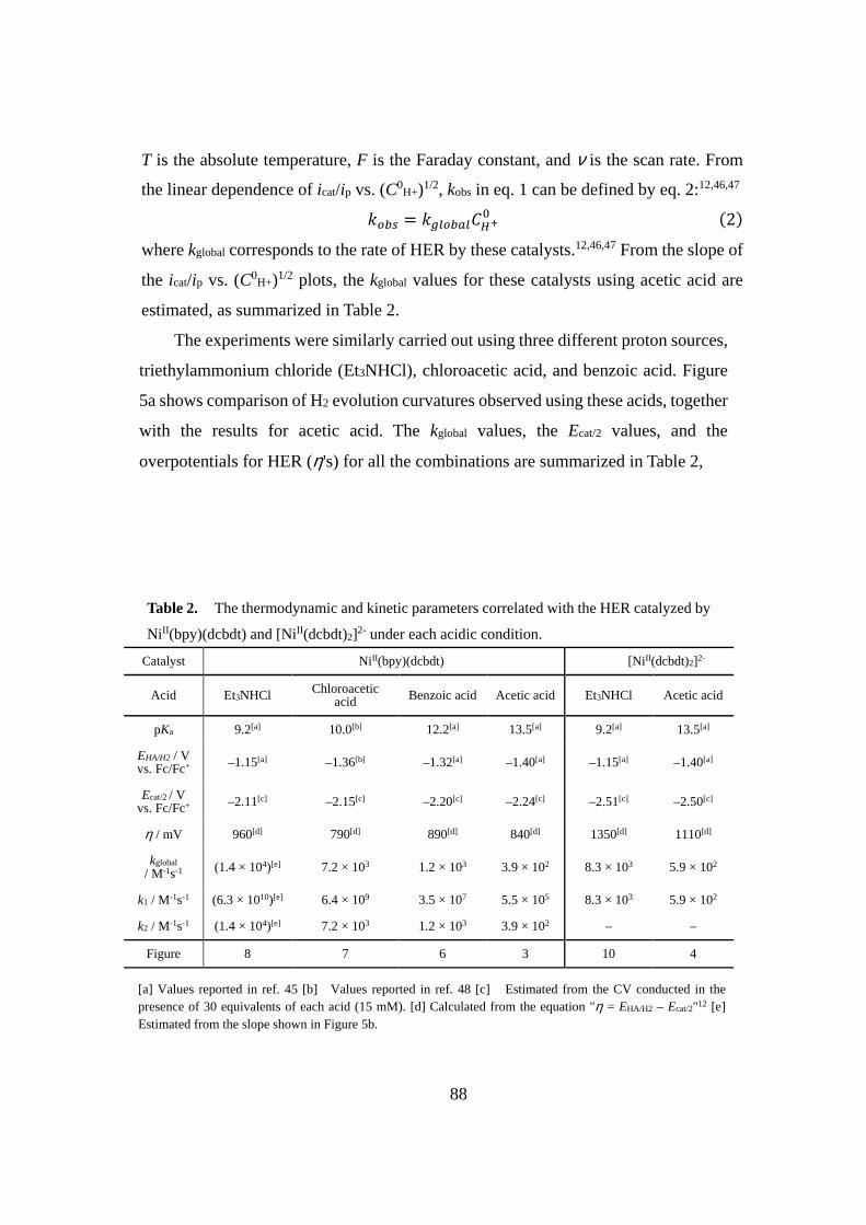
88
T is the absolute temperature, F is the Faraday constant, and ν is the scan rate. From
the linear dependence of icat/ip vs. (C0H+)1/2, kobs in eq. 1 can be defined by eq. 2:12,46,47 ���� = ����������� �2�
where kglobal corresponds to the rate of HER by these catalysts.12,46,47 From the slope of
the icat/ip vs. (C0H+)1/2 plots, the kglobal values for these catalysts using acetic acid are
estimated, as summarized in Table 2.
The experiments were similarly carried out using three different proton sources,
triethylammonium chloride (Et3NHCl), chloroacetic acid, and benzoic acid. Figure
5a shows comparison of H2 evolution curvatures observed using these acids, together
with the results for acetic acid. The kglobal values, the Ecat/2 values, and the
overpotentials for HER (η's) for all the combinations are summarized in Table 2,
Table 2. The thermodynamic and kinetic parameters correlated with the HER catalyzed by
Ni II(bpy)(dcbdt) and [NiII(dcbdt)2]2- under each acidic condition.
Catalyst Ni II(bpy)(dcbdt) [Ni II(dcbdt)2]2-
Acid Et3NHCl Chloroacetic acid Benzoic acid Acetic acid Et3NHCl Acetic acid
pKa 9.2[a] 10.0[b] 12.2[a] 13.5[a] 9.2[a] 13.5[a]
EHA/H2 / V vs. Fc/Fc+ –1.15[a] –1.36[b] –1.32[a] –1.40[a] –1.15[a] –1.40[a]
Ecat/2 / V
vs. Fc/Fc+ –2.11[c] –2.15[c] –2.20[c] –2.24[c] –2.51[c] –2.50[c]
η / mV 960[d] 790[d] 890[d] 840[d] 1350[d] 1110[d]
kglobal / M-1s-1 (1.4 × 10⁴)[e] 7.2 × 10³ 1.2 × 10³ 3.9 × 10² 8.3 × 10³ 5.9 × 10²
k1 / M-1s-1 (6.3 × 10¹⁰)[e] 6.4 × 10⁹ 3.5 × 10⁷ 5.5 × 10⁵ 8.3 × 10³ 5.9 × 10²
k2 / M-1s-1 (1.4 × 10⁴)[e] 7.2 × 10³ 1.2 × 10³ 3.9 × 10² – –
Figure 8 7 6 3 10 4
[a] Values reported in ref. 45 [b] Values reported in ref. 48 [c] Estimated from the CV conducted in the presence of 30 equivalents of each acid (15 mM). [d] Calculated from the equation "η = EHA/H2 – Ecat/2"12 [e] Estimated from the slope shown in Figure 5b.

89
Figure 5 (a) Acid dependence of linear sweep voltammograms (LSVs) for DMF solutions of 0.5
mM NiII(bpy)(dcbdt) in ther presence of 30 equivalents of Et3NHCl (pKaDMF = 9.2�� ���),45
chloroaectic acid (pKaDMF ��������������48 benzoic acid (pKa
DMF �������� � �������45 and acetic
acid (pKaDMF �� ������ ������45 containing 0.1 M n-Bu4NPF6 at room temperature under Ar
atmosphere, recorded at a sweep rate of 100 mVs-1. (b) Plots of log(k1) (blue) and log(k2) (green)
versus pKa of acids. The value of Et3NHCl (blank circle) was estimated from each slope, which
shows the linear free energy relationship (see also Figure 3 and 6-9).
-2.5-2.0-1.5-1.0
0
50
100
150
200C
urre
nt /
µA
Potential / V vs. Fc/Fc +
8 9 10 11 12 13 140
5
10
15
log(
k)
pKa
(a)
(b)
Acetic acid
Benzoic acid
Chloroacetic acidEt3NHCl
Et3NHClChloroacetic acidBenzoic acidAcetic acidNo acid

90
Figure 6. CVs for DMF solutions of 0.5 mM NiII(bpy)(dcbdt) in the presence of 0-30 equivalents
of benzoic acid (pKaDMF = 12.2, E0,solv
HA/H2 = –1.32 V vs. Fc/Fc+)45 containing 0.1 M n-Bu4NPF6
at room temperature under Ar atmosphere, recorded at a sweep rate of 100 mVs-1. The inset shows
the icat/ip vs. (C0H+)1/2 plots under these conditions.
Figure 7. CVs for DMF solutions of 0.5 mM NiII(bpy)(dcbdt) in the presence of 0-30 equivalents
of chloroacetic acid (pKaDMF = 10.0, E0,solv
HA/H2 = –1.36 V vs. Fc/Fc+)48 containing 0.1 M n-
Bu4NPF6 at room temperature under Ar atmosphere, recorded at a sweep rate of 100 mVs-1. The
inset shows the icat/ip vs. (C0H+)1/2 plots under these conditions.
0.0 0.10
5
10
15
i cat
/ i p
(C0H+)1/2
-2.5-2.0-1.5-1.0
0
50
100C
urre
nt /
µA
Potential / V vs. Fc/Fc +
30 eq25 eq20 eq15 eq10 eq5 eq0 eq
-2.5-2.0-1.5-1.0
0
50
100
150
Cur
rent
/ µA
Potential / V vs. Fc/Fc +
0.0 0.10
10
20
i cat
/ i p
(C0H+)1/2
30 eq25 eq20 eq15 eq10 eq5 eq0 eq

91
Figure 8. CVs for DMF solutions of 0.5 mM NiII(bpy)(dcbdt) in the presence of 0-30 equivalents
of triethylammonium chloride (pKaDMF = 9.2, E0,solv
HA/H2 = –1.15 V vs. Fc/Fc+)45 containing 0.1
M n-Bu4NPF6 at room temperature under Ar atmosphere, recorded at a sweep rate of 100 mVs-1.
The inset shows the icat/ip vs. C0H+ plots under these conditions.
Figure 9. CVs for DMF solutions of 0.5 mM NiII(bpy)(dcbdt) in the presence of 0-4 equivalents
of triethylammonium chloride (pKaDMF = 9.2, E0,solv
HA/H2 = –1.15 V vs. Fc/Fc+)45 containing 0.1
M n-Bu4NPF6 at room temperature under Ar atmosphere, recorded at a sweep rate of 100 mVs-1.
30 eq25 eq20 eq15 eq10 eq5 eq0 eq
-2.5-2.0-1.5-1.0
0
50
100
150
200C
urre
nt /
µA
Potential / V vs. Fc/Fc +
0.00 0.01 0.020
10
20
30
i cat
/ i p
C0H+
-2.5-2.0-1.5-1.0
0
20
Cur
rent
/ µA
Potential / V vs. Fc/Fc +
0 eq1 eq2 eq3 eq4 eq

92
Figure 10. CVs for DMF solutions of 0.5 mM (n-Bu4N)2[Ni II(dcbdt)2] in the presence of 0-30
equivalents of triethylammonium chloride (pKaDMF = 9.2, E0,solv
HA/H2 = –1.15 V vs. Fc/Fc+)45
containing 0.1 M n-Bu4NPF6 at room temperature under Ar atmosphere, recorded at a sweep rate
of 100 mVs-1.
0.0 0.10
10
20
30
i cat
/ i p
(C0H+)1/2
-2.5-2.0-1.5-1.0
0
50
100
150
Cur
rent
/ µA
Potential / V vs. Fc/Fc +
30 eq25 eq20 eq15 eq10 eq5 eq0 eq

93
Among various molecular catalysis routes defined by Savéant et al.,46 it is found
the EECC′ mechanism depicted in Scheme 3 is the most suitable one to explain the
electrode processes adopted for the HER by the present heteroleptic NiII(bpy)(dcbdt)
catalyst.
Scheme 3. The catalytic scheme of EECC mechanism,46 where O, P, Q and B correspond to
Ni II(bpy)(dcbdt), [NiI(bpy)(dcbdt)]‒, [Ni I(bpy‒•)(dcbdt)]2– and [NiII(H)(bpy)(dcbdt)]‒,
respectively.
The validity of this choice is also supported by the DFT results, which will be
discussed in a later section. Eqs. 3 and 4 correspond to the definition of kglobal and
Ecat/2 for this mechanism.46
w������� = x��1 0 x��
�� y1 0 x�x��z�3�
≈ x�
!��� � = !)�+� 0 ��� ��{||}1 0 x��
�� y1 0 x�x��z~��� �4�
≈ !)�+� 0 ��� �� y1 0 x��x�z
The most remarkable fearture is that the onset potential as well as Ecat/2 for the HER
catalyzed by NiII(bpy)(dcbdt) shows an anodic shift of ca. 0.1~0.4 V with respect to
the second reduction potential (i.e., E0P/Q), as depicted in Figure 5a. A reasonable
O + e– P
P + e– Q
Q + H+ B
B + H+ O + H2
E0O/P
E0P/Q
k1
k2

94
interpretation is that the second term in eq. 4 has a positive value. This tendency
becomes more obvious as the pKa is decreased (see the onset potential, together with
Ecat/2 for the red line (i.e., Et3NHCl case) in Figure 5a, in which the catalytic current
starts to flow at ca. –2.0 V vs. Fc/Fc+). In order to observe such behaviors, a condition
of k2C0H+ << k1C0
H+ (i.e., k2 << k1) must be satisfied. The overall assessment is that
(i) the k1 step is a rapid process which follows the second ET process and these two
consecutive paths may be considered as a PCET process on the basis of the ET-PT
scheme, and (ii) the final k2 step is a relatively slow process consistent with the
definition of the EECC′ mechanism with the last step being the RDS.
Using eqs. 3 and 4, the rate constants k1 and k2 for the individual acids, except
for Et3NHCl (see below for its explanation), are estimated, as listed in Table 2.
Importantly, the logarithm of either k1 or k2 shows a linear dependence on pKa,
consistent with that both rates are limited by the proton abstraction from each acid
(see Figure 5b and Scheme 4). As discussed above, the present catalysis of HER falls
into a category for which the rate of HER is relatively slow and the diffusion of acid
into the electrode surface does not limit the catalytic cycle, as observed by the linear
dependence on icat/ip vs. (C0H+)1/2 (see Figure 3, 6 and 7). It is important to note here
that, in general, the pKa governs whether the rate of catalysis or diffusion of acid
limits the overall reaction rate of HER.47,49 It has been well documented that the
diffusion of acid tends to limit the overall reaction rate when the catalytic cycle is
rapid due to the low pKa condition. For such cases, the icat/ip value shows a linear
dependence on C0H+ (Figure 8). To the contrary, the catalytic cycle limits the overall
reaction rate when the catalytic process is slower relative to the diffusion of acid. In
the latter case, the icat/ip shows a linear dependence on (C0H+)1/2, which is exactly the
case adopted by NiII(bpy)(dcbdt) for most of the acids tested. However, the catalysis
using Et3NHCl having the lowest pKa adopts the former category. As supplied as
Figure 8, the icat/ip is linearly correlated with C0H+. Moreover, the non-catalytic wave
corresponding to the [NiI(bpy)(dcbdt)]–/[Ni I(bpy‒•)(dcbdt)]2– redox couple, is seen
after the flow of catalytic current (see Figure 9), indicating that the diffusion of acid
is not fast enough to flow catalytic current at ca. –2.4 V vs. Fc/Fc+.

95
Scheme 4. The H2 elimination path after formation of [NiI(bpy‒•)(dcbdt)]2–, which proceeds via
the consecutive protonation (PT) steps.

96
The mechanism of the HER by [NiII(dcbdt)2]2– was similarly analyzed on the
basis of the CV experiments, as depicted in Figure 11. In sharp contrast with
Ni II(bpy)(dcbdt), the onset potential and Ecat/2 for HER are little shifted upon
changing the pKa of acid with their potentials kept close to the first reduction potential
of [Ni II(dcbdt)2]2– observed in the absence of acid (E1/2 = –2.51 V vs. Fc/Fc+) (see
Table 2).These pKa-independent behaviors indicate that the k1 path is the RDS.46
Although an ambiguity remains in classification of the mechanism after the RDS, it
is assumed the EC′EC mechanism (Scheme 5) is a plausible one, as discussed below.
The DFT results are also in line with this selection (see below).
Figure 11 Acid dependence of LSVs for DMF solutions of 0.5 mM [Ni II(dcbdt)2]2- in the presence
of 30 equivalents of Et3NHCl (red),45 and acetic acid (green)45 under the conditions similar to
Figure 5a (see also Figure 4 and 10).
Scheme 5. The reaction scheme of ECEC mechanism,46 where P, Q, Q' and B correspond to
[Ni II(dcbdt)2]2–, [Ni II(dcbdt‒•)(dcbdt)]3–, [Ni III (-H)(dcbdt)2]2– and [NiII(-H)(dcbdt)2]3–,
respectively.
-2.5-2.0-1.5-1.0
0
50
100
150
200
Cur
rent
/ µA
Potential / V vs. Fc/Fc +
No acidAcetic acidEt3NHCl
P + e– Q
Q + H+ Q'
Q' + e– B
B + H+ P + H2
E0P/Q
k1
E0Q'/B
k2

97
For this mechanism, under the conditions of k1C0H+ << k2C0
H+ (i.e., k1 << k2) and
E0P/Q < E0
Q'/B, the following eqs. 5 and 6 are satisfied.46
w������� = x�� �5� !��� � = !) +�� �6�
To ensure the homogeneous nature of the HER by these catalysts, the so-called
"rinse test"25 was conducted. In these experiments, the glassy carbon electrode once
used for observing the electrocatalytic HER by each catalyst was taken out from the
catalysis solution, and was then sweeped under the same CV conditions using a fresh
electrolyte solution which does not contain any catalyst. As no catalytic current flows
at the rinse test for both catalysts (Figure 12-15), deposition of any active species,
such as heterogeneous materials, can be ruled out, although deposition of unidentified
less catalytically active species was not negligible when the fastest catalytic cycle
was promoted using Et3NHCl (Figure 16-17). It is also important to note that the H2
evolved during the electrocatalytic HER by either catalyst was qualitatively detected
by using the gas chromatographic technique (data not shown), even though the
quantitative factors remain unexplored due to inevitable deposition of the catalyst at
the prolonged electrolysis time.

98
Figure 12. A LSV (red) with use of a GC working electrode for DMF solution of 0.5 mM
Ni II(bpy)(dcbdt) in the presence of 0.1 M n-Bu4NPF6 and 15 mM acetic acid ���������KaDMF =
13.5, E0,solvHA/H2 = –1.40 V vs. Fc/Fc+)45. The CV result of rinse test after the 1st scan (blue),
recorded after replacing the electrolysis solution with the same solution free of the catalyst. It
indicates that no materials are absorbed over the GC electrode after 1 scan of CV. All these
electrochemical measurements are recorded at a sweep rate of 100 mV/s, under Ar atmosphere at
room temperature.
Figure 13. A LSV (red) with use of a GC working electrode for DMF solution of 0.5 mM
Ni II(bpy)(dcbdt) in the presence of 0.1 M n-Bu4NPF6 and 15 mM benzoic acid ���������KaDMF
= 12.2, E0,solvHA/H2 = –1.32 V vs. Fc/Fc+)45. The CV result of rinse test after the 1st scan (blue),
recorded after replacing the electrolysis solution with the same solution free of the catalyst. It
indicates that no materials are absorbed over the GC electrode after 1 scan of CV. All these
electrochemical measurements are recorded at a sweep rate of 100 mV/s, under Ar atmosphere at
room temperature.
Blank0.5 mM Ni(bpy)(dcbdt) 1 sweepRinse test
-2.5-2.0-1.5-1.0
0
20
40
60
80
Cur
rent
/ µA
Potential / V vs. Fc/Fc +
Blank0.5 mM Ni(bpy)(dcbdt) 1 sweepRinse test
-2.5-2.0-1.5-1.0
0
50
100
Cur
rent
/ µA
Potential / V vs. Fc/Fc +

99
Figure 14. A LSV (red) with use of a GC working electrode for DMF solution of 0.5 mM
Ni II(bpy)(dcbdt) in the presence of 0.1 M n-Bu4NPF6 and 15 mM chloroacetic acid ��������
pKaDMF = 10.0, E0,solv
HA/H2 = –1.36 V vs. Fc/Fc+)48. The CV result of rinse test after the 1st scan
(blue), recorded after replacing the electrolysis solution with the same solution free of the catalyst.
It indicates that no materials are absorbed over the GC electrode after 1 scan of CV. All these
electrochemical measurements are recorded at a sweep rate of 100 mV/s, under Ar atmosphere at
room temperature.
Figure 15. A LSV (red) with use of a GC working electrode for DMF solution of 0.5 mM (n-
Bu4N)2[Ni II(dcbdt)2] in the presence of 0.1 M n-Bu4NPF6 and 15 mM acetic acid ���������KaDMF
= 13.5, E0,solvHA/H2 = –1.40 V vs. Fc/Fc+)45. The CV result of rinse test after the 1st scan (blue),
recorded after replacing the electrolysis solution with the same solution free of the catalyst. It
indicates that no materials are absorbed over the GC electrode after 1 scan of CV. All these
electrochemical measurements are recorded at a sweep rate of 100 mV/s, under Ar atmosphere at
room temperature.
-2.5-2.0-1.5-1.0
0
20
40
60
80
Cur
rent
/ µA
Potential / V vs. Fc/Fc +
Blank0.5 mM [Ni(dcbdt)2]2- 1 sweepRinse test
-2.5-2.0-1.5-1.0
0
50
100
150
Cur
rent
/ µA
Potential / V vs. Fc/Fc +
Blank0.5 mM Ni(bpy)(dcbdt) 1 sweepRinse test

100
Figure 16. A LSV (red) with use of a GC working electrode for DMF solution of 0.5 mM
Ni II(bpy)(dcbdt) in the presence of 0.1 M n-Bu4NPF6 and 15 mM triethylammonium chloride (15
�����KaDMF = 9.2, E0,solv
HA/H2 = –1.15 V vs. Fc/Fc+)45. The CV result of rinse test after the 1st
scan (blue), recorded after replacing the electrolysis solution with the same solution free of the
catalyst. It reveals that the catalyst is partly absorbed over the GC electrode. All these
electrochemical measurements are recorded at a sweep rate of 100 mV/s, under Ar atmosphere at
room temperature.
Figure 17. A LSV with use of a GC working electrode for DMF solution of [NiII(dcbdt)2]2- (0.5
mM) in the presence of n-Bu4NPF6 (0.1 M) and triethylammonium chloride ���������KaDMF =
9.2, E0,solvHA/H2 = –1.15 V vs. Fc/Fc+)45. The CV result of rinse test after the 1st scan (blue),
recorded after replacing the electrolysis solution with the same solution free of the catalyst. It
reveals that the catalyst is partly absorbed over the GC electrode. All these electrochemical
measurements are recorded at a sweep rate of 100 mV/s, under Ar atmosphere at room
temperature.
-2.5-2.0-1.5-1.0
0
50
100
150
200
Cur
rent
/ µA
Potential / V vs. Fc/Fc +
Blank0.5 mM Ni(bpy)(dcbdt) 1 sweepRinse test
-2.5-2.0-1.5-1.0
0
50
100
150
200
Cur
rent
/ µA
Potential / V vs. Fc/Fc +
Blank0.5 mM [Ni(dcbdt)2]2- 1 sweepRinse test

101
DFT Calculations Some important insights into the mechanism of the HER by NiII(bpy)(dcbdt)
and [NiII(dcbdt)2]2– were given by DFT calculations. As shown in Figure 18, the
initial reduction process for NiII(bpy)(dcbdt) is unambiguously assigned as a simple
one-electron reduction of the dissolved catalyst. The computed first reduction
potential (Ecal), which is assigned as the Ni(II/I) on the basis of the Mulliken spin
density at the Ni center (ρNi = 0.86) in the reduction product (see Figure 19), is almost
consistent with the observed potential (Eobs). A square scheme showing possible
reduction and protonation products can be also developed (Figure 18). The results
clearly indicate that the ET-PT path is the much more favorable for the subsequent
process, in which the bpy-based reduction proceeds as the second reduction to afford
[Ni I(bpy–•)(dcbdt)]2– (i.e., 2e–-0H+ �������� Figure 20), Protonation of this product
further affords the two-electron-reduced singly protonated species
[Ni II(H)(bpy)(dcbdt)]– (i.e., 2e–-1H+ species). This hydridonickel(II) intermediate
has a square-planar geometry (see also Figure 22). The PT-ET path is largely
disfavored under the pKaDMF = 13.5 condition adopted in the above experiments
considering the pKa value of 2.3 for the protonation of [NiI(bpy)(dcbdt)]– (i.e., 1e–-
0H+ species). In the same manner, more protonation of the above hydridonickel(II)
species (i.e., 2e–-1H+ species) is largely disfavored due to the low pKa value (7.0)
computed for this path. Moreover, the calculations also reveal that the reduction of
this hydride intermediate can only be promoted at Ecal = –2.40 V, which is rather
cathodic relative to the potential where the catalytic current for the HER flows (ca. –
2.2 V, see Figure 5a).

102
������� ��� ������������� ���� ����������� �������������� ����������� ���� ���� ��������������
��������������������������������������������������������������������������������������������������
�������������������������������������������������������������������������������������������������
�����������������������������������������������������������������������������������������������
���������������������������������������������������������������

103
������� ���� ���� ����� ���� ���� ���� ��������� ���� ��� ��������������������� �������� ���
�������������������������������������������������������������������������������������������������
��������������������������������������������������������������������������������������������
��������������ρNi�����������������������������������

104
�������������������������������������������������������������������������������������������
�����������������������������������������������������������������������������������������������������
���������� ��� ���� ������������������� ������ ��� ���� ����� ���������� ��� ���� ������ �����
������������������������������������������������������������������ρNi���������������������������
��������

105
���������������������������������������������������������������������������������������������
����������������������������������������������������������������

106
���������������������������������������������������������������������������������������������
�����������������������������������������������������������������

107
��������������������������������������������������������������������������������
���������� ����� ���� ���������� ��� ����������������� ������� �������� ��������� �����
������������������‒����������������������������������������������������������������������
������������ ����������������������������������������������������������������������
��������������������������������������������������������������������������������������
���������������������������������������������������������������������������������������
��������������������������������������������������������������������������������������
��������ρNi������������������������������������������������������������������������������
������������������������������������������������������������������������������������������
���� ��������� ��� ������� �� �� ����� ��������� ����� ���� ���������� ���������� ���
������������������������������������������������������������������������������������������
��������� ��������� ��� ������� ���� �������������������� ������� �������� ���������� ����
���������� ������ ��� ����������� ��� ��′��� ������� ����������� ����� �������������
�������������
������� ���� ������������� ���� ����������� �������������� ����������� ���� ���� ��������������
����������������������������������������‒���������������������������������������������������������
�������������������������������������������������������������������������������������������������
�������������������������������������������������������������������������������������������������
�����������������������������������������������������������������

108
���������������������������������������������������������������������������������������������
������� ��������� ��� ���� �������� ������� ���������� ��� ����������������������� ������ ��� ���������
����������������������������������������������������������������������������������������������
ρNi�≈�������������������������������
��������������������������������������������������������������������������������������������
��������������������������������������������������������

109
���������������������������������������������������������������������������������������������
��������������������������������������������������������
���������������������� ���� ��������������� ���� ���������������������������� ���
����������������������������������������� ���������������������� ��������′� ������ ���
����� �������� ����� ���� ����� ��� ������������ ����� ������ ����������� �∆G = –14.76
����������� ���������� ���� ������� �������� ���������� ���� ���� ���������� ���
����������������� ��� ����������� ����� ���� ��′��� ���������� �������� ����� ���� �����
����������� ���� �������������������� �������� ���������������������������������������
��������������������������������������������������������������������

110
Scheme 6. Free energy changes relevant to the catalytic processes by NiII(bpy)(dcbdt) (M ) under
each acidic condition, developed in the same manner as reported elsewhere 44b
2H+ + 2e– → H2 E02H
+/H2 = –1.40 (V vs. Fc/Fc+��������������
–1.32 (V vs. Fc/Fc+���������������
–1.15 (V vs. Fc/Fc+����3NH+)
∆G2H+
/H2 = –2F(E02H
+/H2 – E)
AH → A– + H+
pKaDMF = 13.5 (acetic acid)
12.2 (benzoic acid)
9.2 (Et3NH+)
∆GAH/A–H
+ = RTln(10) × pKaDMF
M + e– → M– E0M /M
–,cal = –1.470 (V vs. Fc/Fc+)
∆GM–/M
2– = –F(E0M /M
–,cal – E)
M– + e– → M2– E0M
–/M
2–,cal = –2.304 (V vs. Fc/Fc+)
∆GM–/M
2–= –F(E0M
–/M
2–,cal – E)
M2– + H+ → MH – pKa,M2–
/MH–,cal = 17.45
∆GM2–
/MH– = –RTln(10) × (pKa,M
2–/MH
–,cal – pKa
DMF)
MH – + H+ → M + H2
∆G MH–/M+H2 = ∆G2H
+/H2 – ∆GM
–/M
2– – ∆GM–/M
2– – ∆GM2–
/MH–

111
Figure 27. Free energy diagram for the catalytic pathway of NiII(bpy)(dcbdt) for HER. Relative
free energy for half reactions corresponding to electron transfer processes are calculated with
respect to the 1e--0H+/2e--0H+ couple (Ecal = -2.30 V vs. Fc/Fc+).
Figure 28. The acid dependence of free energy diagrams for the catalytic pathways of
Ni II(bpy)(dcbdt) for HER. Relative free energy for half reactions corresponding to electron
transfer processes are calculated with respect to the 1e--0H+/2e--0H+ couple (Ecal = -2.30 V vs.
Fc/Fc+).
-40
-30
-20
-10
0R
elat
ive
free
ene
rgy
(kca
l/mol
)
-2.0
-1.5
-1.0
-0.5
0.0
Relative free energy (eV
)
0.0
-19.23 -19.23
0e--0H+
1e--0H+ 2e--0H+
2e--1H+
0e--0H+ + H2
+e-
+H+
+e-
+H+
Reference 1e--0H+/2e--0H+
(-2.30 V vs. Fc/Fc+)
+H+
-3.88
1e--1H+
-15.772e--2H+
-24.653e--1H+
-41.70
+e-
+H+
-26.94
-50
-40
-30
-20
-10
0
Rel
ativ
e fr
ee e
nerg
y (k
cal/m
ol)
-2.5
-2.0
-1.5
-1.0
-0.5
0.0
Relative free energy (eV
)
-50
-40
-30
-20
-10
0
Rel
ativ
e fr
ee e
nerg
y (k
cal/m
ol)
-2.5
-2.0
-1.5
-1.0
-0.5
0.0
Relative free energy (eV
)
-50
-40
-30
-20
-10
0
Rel
ativ
e fr
ee e
nerg
y (k
cal/m
ol)
-2.5
-2.0
-1.5
-1.0
-0.5
0.0
Relative free energy (eV
)
0.0
-19.23 -19.23
AcOHPhCOOH
Et3NHCl
0e--0H+
1e--0H+ 2e--0H+
2e--1H+
0e--0H+ + H2
e-
H+e-
H+
Reference 1e--0H+/2e--0H+
(-2.30 V vs. Fc/Fc+)
-26.94-28.72-32.81
-41.70-45.39
-53.23

112
Figure 29. The acid dependence of free energy diagrams for the catalytic pathways of
[Ni II(dcbdt)2]2- for HER. Relative free energy for half reactions corresponding to electron transfer
processes are calculated with respect to the 0e--0H+/1e--0H+ couple (Ecal = -2.76 V vs. Fc/Fc+).
-80
-70
-60
-50
-40
-30
-20
-10
0
Rel
ativ
e fr
ee e
nerg
y (k
cal/m
ol)
-3.5
-3.0
-2.5
-2.0
-1.5
-1.0
-0.5
0.0
Relative free energy (eV
)
-80
-70
-60
-50
-40
-30
-20
-10
0
Rel
ativ
e fr
ee e
nerg
y (k
cal/m
ol)
-3.5
-3.0
-2.5
-2.0
-1.5
-1.0
-0.5
0.0
Relative free energy (eV
)
0e--0H+ 1e--0H+
1e--1H+
2e--1H+
0e--0H+ + H2
e-H+
e-
H+
Reference 0e--0H+/1e--0H+
(-2.76 V vs. Fc/Fc+)
AcOH
Et3NHCl
0.0 0.0
-8.30-14.17
-30.98-36.85
-44.30
-61.70

113
Based on the above results, possible schemes for the catalytic cycles of two
catalysts are proposed in Figure 30 As depicted in this figure, the pKa values of the
initially formed hydride intermediates can be estimated as pKa = 19-20, indicating
that the basicity of nickel centers is essentially similar to each other after the
formation of these metal hydrides. It is thus reasonable to consider that the essential
difference in the rate of proton abstraction is rather caused by the considerable
difference in the basicity of the precursor that interacts with the proton sources. In
the DFT results, it is noticed that the first reduction product for the homoleptic
catalyst, i.e., [NiII(dcbdt)(dcbdt‒•)]3–, has a SOMO spread over the two dcbdt ligands
with no hybridization of metal d orbitals (see Figure 24), indicating that electron
injection into this orbital has a relatively small contribution to raise the basicity of
the filled dz2 orbital at the Ni(II) d8 center. On the other hand, there are two SOMO’s
in the doubly reduced heteroleptic catalyst, i.e., [Ni I(bpy–•)(dcbdt)]2– with both
orbitals more or less mixed with the metal d orbitals (see Figure 20). The lower-
energy SOMO (–4.43 eV) corresponds to the metal-ligand antibonding couple with
relatively high contributions from two dithiolate sulfur 3p orbitals. Moreover, the
higher-energy SOMO (–3.36 eV) is derived from the π*(bpy) orbital with effective
contributions from the nitrogen 2p orbitals and small but non-negligible contributions
from the metal d-orbitals. It must be therefore emphasized in the end that the electron
filling in these two SOMO’s largely contribute to raise the basicity of the filled dz2
orbital due to their closer location with regard to the filled dz2 orbital. These well
rationalize the reason why the heteroleptic system can achieve substantial increase in
the proton abstraction rate required to promote the PCET pathways.

114
Figure 30. Proposed mechanisms of HER catalyzed by (a) Ni II(bpy)(dcbdt) and (b)
[Ni II(dcbdt)2]2–.
(a)
(b)
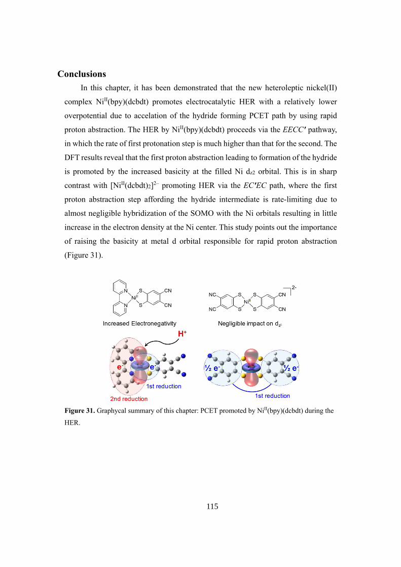
115
����������� ��� ����� ��������� ��� ���� ����� ������������� ����� ���� ����������������� �����������
�������� ����������������� ��������� ����������������� ���� ����� �� ����������� ������
�������������� ���� ��� �������������� ������������ ��������������������������� ������
���������������������������������������������������������������������′����������
�����������������������������������������������������������������������������������������
�����������������������������������������������������������������������������������������
��� ��������� ��� ���� ���������� ��������� ��� ���� ���������� ���� �������������� ��� ��� ������
�������������� ����������������� ������������������ ������′��� ������������ ���� ������
������� ������������ ����� ���������� ���� �������� ������������� ��� �������������� ���� ���
�������������������������������������������������������������������������������������
����������������������������������������������������������������������������������������
��� �������� ���� ��������� ��� ������ �� �������� ������������ ���� ������ ������� ������������
������������
�������������������������������������������������������������������������������������������
����

116
References 1. A. Kudo, Y. Miseki, Chem. Soc. Rev. 2008, 38, 253–278.
2. S. Y. Reece, J. A. Hamel, K. Sung, T. D. Jarvi, A. J. Esswein, J. J. H. Pijpers, D. G.
Nocera, Science 2011, 334, 645–648.
3. J. R. Swierk, T. E. Mallouk, Chem. Soc. Rev. 2013, 42, 2357–2387.
4. T. Hisatomi, J. Kubota, K. Domen, Chem. Soc. Rev. 2014, 43, 7520–7535.
5. A. J. Esswein, D. G. Nocera, Chem. Rev. 2007, 107, 4022–4047.
6. G. W. Brudvig, J. N. H. Reek, K. Sakai, L. Spiccia, L. Sun, ChemPlusChem 2016, 81,
1017–1019.
7. Y. Wang, K. S. Chen, J. Mishler, S. C. Cho, X. C. Adroher, Applied Energy 2011, 88,
981–1007.
8. M. Wang, L. Chen, L. Sun, Energy & Environmental Science 2012, 5, 6763.
9. V. S. Thoi, Y. Sun, J. R. Long, C. J. Chang, Chem. Soc. Rev. 2013, 42, 2388–2400.
10. V. Artero, M. Fontecave, Chem. Soc. Rev. 2013, 42, 2338–2356.
11. J. R. McKone, S. C. Marinescu, B. S. Brunschwig, J. R. Winkler, H. B. Gray, Chem.
Sci. 2014, 5, 865–878.
12. V. Artero, J.-M. Saveant, Energy Environ. Sci. 2014, 7, 3808–3814.
13. M. Frey, ChemBioChem 2002, 3, 153–160.
14. K. A. Vincent, A. Parkin, F. A. Armstrong, Chem. Rev. 2007, 107, 4366–4413.
15. W. Lubitz, H. Ogata, O. Rüdiger, E. Reijerse, Chem. Rev. 2014, 114, 4081–4148.
16. T. Yamaguchi, S. Masaoka, K. Sakai, Chem. Lett. 2009, 38, 434–435.
17. D. Sellmann, M. Geck, M. Moll, J. Am. Chem. Soc. 1991, 113, 5259–5264.
18. H. Lv, T. P. A. Ruberu, V. E. Fleischauer, W. W. Brennessel, M. L. Neidig, R.
Eisenberg, J. Am. Chem. Soc. 2016, 138, 11654–11663.
19. W. R. McNamara, Z. Han, P. J. Alperin, W. W. Brennessel, P. L. Holland, R. Eisenberg,
J. Am. Chem. Soc. 2011, 133, 15368–15371.
20. W. R. McNamara, Z. Han, C.-J. (Madeline) Yin, W. W. Brennessel, P. L. Holland, R.
Eisenberg, Proc. Natl. Acad. Sci. USA 2012, 109, 15594–15599.
21. B. H. Solis, S. Hammes-Schiffer, J. Am. Chem. Soc. 2012, 134, 15253–15256.
22. K. J. Lee, B. D. McCarthy, E. S. Rountree, J. L. Dempsey, Inorg. Chem. 2017, 56,
1988–1998.
23. E. Hontzopoulos, J. Knostantatos, E. Vrachnou-Astra, D. Katakis, J. Mol. Catalysis
1985, 31, 327–333.
24. E. Hontzopoulos, E. Vrachnou-Astra, J. Konstantatos, D. Katakis, J. Photochem. 1985,
30, 117–120.

117
25. M. Fang, M. H. Engelhard, Z. Zhu, M. L. Helm, J. A. S. Roberts, ACS Catal. 2014, 4,
90–98.
26. A. Zarkadoulas, M. J. Field, C. Papatriantafyllopoulou, J. Fize, V. Artero, C. A.
Mitsopoulou, Inorg. Chem. 2016, 55, 432–444.
27. A. Zarkadoulas, M. J. Field, V. Artero, C. A. Mitsopoulou, ChemCatChem 2017, 9,
2308–2317.
28. K. Koshiba, K. Yamauchi, K. Sakai, Angew. Chem. Int. Ed. 2017, 56, 4247–4251.
29. A. Zarkadoulas, E. Koutsouri, E. Semidalas, V. Psycharis, C. P. Raptopoulou, C. A.
Mitsopoulou, Polyhedron 2018, 152, 138–146.
30. Y. Aimoto, K. Koshiba, K. Yamauchi, K. Sakai, Chem. Commun. 2018, 54, 12820-
12823.
31. K. Koshiba, K. Yamauchi, K. Sakai, Dalton Trans. 2019, 48, 635-640.
32. W. T. Eckenhoff, W. W. Brennessel, R. Eisenberg, Inorg. Chem. 2014, 53, 9860–9869.
33. A. Vlček, A. A. Vlček, Inorg. Chim. Acta 1980, 41, 123–131.
34. R. Humphry-Baker, C. A. Mitsopoulou, D. Katakis, E. Vrachnou, J. Photochem.
Photobiol. A 1998, 114, 137–144.
35. M. Gomez-Mingot, J.-P. Porcher, T. K. Todorova, T. Fogeron, C. Mellot-Draznieks, Y.
Li, M. Fontecave, J. Phys. Chem. B 2015, 119, 13524–13533.
36. A. Kochem, T. Weyhermüller, F. Neese, M. van Gastel, Organometallics 2015, 34,
995–1000.
37. D. Simão, H. Alves, D. Belo, S. Rabaça, E. B. Lopes, I. C. Santos, V. Gama, M. T.
Duarte, R. T. Henriques, H. Novais, et al., Eur. J. Inorg. Chem. 2001, 2001, 3119–3126.
38. C. L. Linfoot, P. Richardson, K. L. McCall, J. R. Durrant, A. Morandeira, N. Robertson,
Solar Energy 2011, 85, 1195–1203.
39. D. G. Yakhvarov, E. Hey-Hawkins, R. M. Kagirov, Y. H. Budnikova, Y. S.
Ganushevich, O. G. Sinyashin, Russ. Chem. Bull. 2007, 56, 935–942.
40. Gaussian 16, Revision A.03, M. J. Frisch, G. W. Trucks, H. B. Schlegel, G. E. Scuseria,
M. A. Robb, J. R. Cheeseman, G. Scalmani, V. Barone, G. A. Petersson, H. Nakatsuji, X.
Li, M. Caricato, A. V. Marenich, J. Bloino, B. G. Janesko, R. Gomperts, B. Mennucci, H.
P. Hratchian, J. V. Ortiz, A. F. Izmaylov, J. L. Sonnenberg, D. Williams-Young, F. Ding,
F. Lipparini, F. Egidi, J. Goings, B. Peng, A. Petrone, T. Henderson, D. Ranasinghe, V. G.
Zakrzewski, J. Gao, N. Rega, G. Zheng, W. Liang, M. Hada, M. Ehara, K. Toyota, R.
Fukuda, J. Hasegawa, M. Ishida, T. Nakajima, Y. Honda, O. Kitao, H. Nakai, T. Vreven,
K. Throssell, J. A. Montgomery, Jr., J. E. Peralta, F. Ogliaro, M. J. Bearpark, J. J. Heyd,
E. N. Brothers, K. N. Kudin, V. N. Staroverov, T. A. Keith, R. Kobayashi, J. Normand, K.
Raghavachari, A. P. Rendell, J. C. Burant, S. S. Iyengar, J. Tomasi, M. Cossi, J. M. Millam,

118
M. Klene, C. Adamo, R. Cammi, J. W. Ochterski, R. L. Martin, K. Morokuma, O. Farkas,
J. B. Foresman, and D. J. Fox, Gaussian, Inc., Wallingford CT, 2016.
41. (a) J. P. Perdew, Phys. Rev. B 1986, 33, 8822–8824.; (b) A. D. Becke, J. Chem. Phys.
1993, 98, 5648–5652.
42. (a) V. Barone, M. Cossi, J. Phys. Chem. A 1998, 102, 1995–2001.; (b) M. Cossi, N.
Rega, G. Scalmani, V. Barone, J. Comput. Chem. 2003, 24, 669–681.
43. (a) B. H. Solis, S. Hammes-Schiffer, Inorg. Chem. 2014, 53, 6427–6443.; (b) B. H.
Solis, A. G. Maher, D. K. Dogutan, D. G. Nocera, S. Hammes-Schiffer, Proc. Natl. Acad.
Sci. USA 2016, 113, 485–492.; (c) M. T. Huynh, W. Wang, T. B. Rauchfuss, S. Hammes-
Schiffer, Inorg. Chem. 2014, 53, 10301–10311.; (d) D. K. Bediako, B. H. Solis, D. K.
Dogutan, M. M. Roubelakis, A. G. Maher, C. H. Lee, M. B. Chambers, S. Hammes-
Schiffer, D. G. Nocera, Proc. Natl. Acad. Sci. USA 2014, 111, 15001–15006.
44. (a) B. H. Solis, S. Hammes-Schiffer, Inorg. Chem. 2011, 50, 11252–11262.; (b) S.
Horvath, L. E. Fernandez, A. M. Appel, S. Hammes-Schiffer, Inorg. Chem. 2013, 52,
3643–3652.; (c) B. H. Solis, A. G. Maher, T. Honda, D. C. Powers, D. G. Nocera, S.
Hammes-Schiffer, ACS Catal. 2014, 4, 4516–4526.; (d) B. H. Solis, S. Hammes-Schiffer,
J. Am. Chem. Soc. 2011, 133, 19036–19039.; (e) S. Chen, R. Rousseau, S. Raugei, M.
Dupuis, D. L. DuBois, R. M. Bullock, Organometallics 2011, 30, 6108–6118. (f)B. A.
Anjali, F. B. Sayyed, C. H. Suresh, J. Phys. Chem. A 2016, 120, 1112–1119.
45. V. Fourmond, P.-A. Jacques, M. Fontecave, V. Artero, Inorg. Chem. 2010, 49, 10338–
10347.
46. C. Costentin, J.-M. Savéant, ChemElectroChem 2014, 1, 1226–1236.
47. E. S. Rountree, D. J. Martin, B. D. McCarthy, J. L. Dempsey, ACS Catal. 2016, 6, 3326–
3335.
48. G. A. N. Felton, R. S. Glass, D. L. Lichtenberger, D. H. Evans, Inorg. Chem. 2006, 45,
9181–9184.
49. J.-M. Savéant, Elements of Molecular and Biomolecular Electrochemistry: An
Electrochemical Approach to Electron Transfer Chemistry, J. Wiley & Sons, Inc, Hoboken,
NJ, 2006.

119
Concluding Remarks
Development of the energy conversion process from electricity to hydrogen or
other chemical has been widely studied to realize the clean and renewable energy
society. Inspired by the reaction centers of hydrogenases in nature, which show
similar catalytic activities for hydrogen evolution reaction (HER) to noble metal
heterogeneous catalysts, molecular catalysts for HER having 1st row metal ions have
been studied in the last decades. Among these studies, redox-active ligands including
dithiolenes were found to enhance the proton-coupled electron transfer (PCET)
process, which is essential to establish the effective molecular catalysts for HER.
However, in the previous studies of metal bis(dithiolene) complexes as the catalysts
for HER, the PCET triggered by the ligand-based reduction is rate-determining
during the catalysis, especially under neutral acidic conditions. In this context, the
author has attempted to develop nickel(II) dithiolene molecular catalysts for
electrochemical HER by promoting the ligand-based PCET reductions. Furthermore,
the mechanisms of HER were elucidated by electrochemical and computational
studies.
In Chapter 1, a nickel pyrazinedithiolate ([NiII(dcpdt)2]2‒�� ������ �� ���-
dicyanopyrazine-2,3-dithiolate), having a dithiolene structure, is shown to serve as
an efficient molecular catalyst for HER in fully aqueous media. This catalyst shows
effectively low overpotentials for HER (330-400 mV at pH = 4-6). Moreover, the
turnover number of catalysis reaches 20000 over the 24-h electrolysis with a high
Faradaic efficiency of 92-100%. The electrochemical and DFT studies reveal that
diprotonated one-electron-reduced species forms at pH < 6.4 via ligand-based PCET
pathways, leading to electrocatalytic HER without applying highly negative potential
required to generate low-valent nickel intermediates.
Chapter 2 successfully clarifies the mechanism of HER catalyzed by
[Ni II(dcpdt)2]2– in water, which proceeds via formation of a square-planar
hydridonickel(II) intermediate given by unprecedented structural transformation of a
doubly-reduced triply-protonated species [NiII(dcpdtH2)(dcpdtH)]–, afforded as a
result of two consecutive ligand-based reductions of [Ni II(dcpdt)(dcpdtH)]– through

120
PCET pathways. DFT caluculations also indicate that the transition state (TS) during
HER, optimized at open-shell singlet state, forms via the intramolecular PCET from
pyrazine to nickel center. This is a rare example of catalyst exhibiting such a behavior.
In Chapter 3, a square-planar NiII(bpy)(dcbdt) hydrogen evolution catalyst is
shown to exhibit a substantial acceleration in the proton abstraction rate due to the
increased basicity at the filled Ni dz2 orbital after formation of [NiI(bpy–•)(dcbdt)]2–
via consecutive two one-electron reductions (bpy = 2,2’-������������ ������ �� ���-
dicyanobenzene-1,2-dithiolate). This catalyst adopts the EECC′ mechanism in which
the rate of the first protonation step is by far higher than that of the second step. The
DFT calculations reveal that the first and second reductions are correlated with the
electron injection into the metal-ligand anti-bonding and π*(bpy) orbitals,
respectively, where the latter orbital shows non-negligible hybridization with the
nickel d orbital. In addition, a homoleptic catalyst [Ni II(dcbdt)2]2– is shown to adopt
the EC′EC mechanism with the rate-determing step being a hydride forming step,
consistent with the largely delocalized nature of the injected electron over the two
dcbdt ligands (π*(dcbdt) orbital). This work demonstrates the importance of raising
the basicity of a metal d orbital relevant to proton abstraction in order to promote
PCET which significantly lowers the overpotential for H2 evolution.
The results demonstrated in this thesis are expected to provide important
strategies towards the molecular designs and development of highly effective
hydrogen evolution catalysts bearing redox-active ligands, which can be realized by
promoting ligand-based PCET pathways.

121
Acknowledgements
This thesis is the summary of the author’s studies obtained during April 2013 to
March 2019, at the Department of Chemistry, Faculty of Science, Kyushu University,
under the direction of Dr. Ken Sakai, Professor at Kyushu University.
The author expresses his sincere gratitude to Professor Ken Sakai and Dr. Kosei
Yamauchi for their significant guidance, continuous encouragement and valuable
discussions. The author had the opportunity to learn various important knowledge
and experimental skills, which have had a great impact on how he designed and
conducted the research topics summarized in this thesis. The author wishes to express
his sincere thanks to Dr. Hironobu Ozawa for his kind support for his research
activities in Sakai Laboratory and the Leading Graduate School Program.
The author is deeply grateful to Professor Andrew A. Gewirth and Professor
Thomas B. Rauchfuss at the University of Illinois at Urbana-Champaign for giving
him the valuable opportunities to study in their laboratories.
The author is also grateful to Professor Sharon Hammes-Schiffer and Dr. Mioy
Huynh at the University of Illinois at Urbana-Champaign for their kindness and
valuable discussion. The aouthor could learn a lot about computational chemistry
from them.
Acknowledgement is made to all the former and present members of Sakai
Laboratory for their valuable suggestions, heartfelt encouragements and friendship.
The author is much indebted for the financial support of Research Fellowship of
the Japan Society for the Promotion of the Science for Young Scientists (DC1). The
author is also much indebted for the financial support from the Advanced Graduate
Course on Molecular Systems for Devices at Kyushu University. The author is also
much indebted for the financial support from the International Institute for Carbon-

122
Neutral Energy Research (WPI-I2CNER), sponsored by the World Premier
International Research Center Initiative (WPI), MEXT, Japan.
Finally, the author wishes to offer his thanks to his family for their continuous,
warm-hearted encouragements and for their financial support.
Keita Koshiba
March, 2019

123
List of Publications
Chapter 1
“A Nickel Dithiolate Water Reduction Catalyst Providing Ligand-Based Proton-
Coupled Electron-Transfer Pathways”
Keita Koshiba, Kosei Yamauchi, and Ken Sakai
Angew. Chem. Int. Ed. 2017, 56, 4247-4251.
Chapter 2
“Consecutive Ligand-based PCET Processes Affording a Doubly Reduced Nickel
Pyrazinedithiolate which Transforms into a Metal Hydride Required to Evolve H2”
Keita Koshiba, Kosei Yamauchi, and Ken Sakai
Dalton Trans., 2019, 48, 635-640.
Chapter 3
“Ligand-based PCET Reduction in an Heteroleptic Ni(bpy)(dcbdt) Electrocatalyst
Leading to a Lower Overpotential for Hydrogen Evolution”
Keita Koshiba, Kosei Yamauchi, and Ken Sakai
Submitted to ChemElectroChem.

124
Other Publications
“電極材料、電極材料の製造方法および還元反応装置”
黄文しん、小柴慧太、古川晴一、宮島友博
特願 K2017-0119、出願日 2017年 11月 6日
“A family of molecular nickel hydrogen evolution catalysts providing tunable
overpotentials using ligand-centered proton-coupled electron transfer paths”
Yutaro Aimoto, Keita Koshiba, Kosei Yamauchi, and Ken Sakai
Chem. Commun. 2018, 54, 12820-12823.