Embed Size (px)
Citation preview

Electrifying
The Midget
Mustang 60
Converting this
high performance
thriller to electric
was surprisingly
simple.
Distributor’s Supplied Specificatins (See Bench Test at End of Article)
Wing Span: 59.5 in / 1510 mm
Wing Area: 6657 sq in / 43.0 sq dm
Flying Weight: 7.5 / 3400 g
Fuselage Length: 51.0 in / 1290 mm
Engine: 2-stroke 0.61 or 4-stroke 0.91
Radio: 4-channel radio with 5 standard servos
Available from The Wings Maker.com
By David Blensky
Page 1 of 1Mustang Page 1
7/1/2011http://www.electricflyermagazine.com/mustang-page-1.html

e’re not really big on “what’s in the box” reviews. In fact, most of them
bore us. So we’re not gong to do that
here. However, when we did open the
box and after carefully examining the
parts, and studying the overall
construction, it became apparent that
this is one hell of a high quality product
that The Wings Maker people have
made available.
So how did we arrive at that conclusion
before even building the kit? By
checking the manufacturer’s attention
to details, the little things, like the way
holes have already been drilled to
accept the control horns, how the pre-
drilled hole for the canopy screws fit
the holes in the canopy
for the fibreglass cowling and wheel
pants. Note how considered were the
designers in supplying grommets for
the screw heads to protect the canopy
and fuselage surfaces.
The included control horns and
connectors are all first class–EZ Links
that connect the push rods to the
servos. No need for a Z Bender
here–just, a 90-degree bend and
snap on the links.
Surely we should be able to find
some glaring fault in this kit? After all,
it IS just an ARF. So we had a look
at the hinge lines. No gaps to be
seen in the elevators; the same can
be said for the ailerons.
The instructions manual that comes
with the Midget Mustang 60 consists
of 11 pages of some of the clearest
instructions we have ever seen with
just one exception: Nowhere does it
indicate the amount of dihedral in
the wings, nor if any is even
necessary. However, the wing joiners
are canted, so if you glue ‘em right I
guess it will be ok. We hope! Any
how, with such great instructions–
other than how we did the electric
conversion–we are not going to bore
you with a step-by-step build. But
some of the design and construction
features are particularly interesting.
Page 1 of 1Mustang Page 2
7/1/2011http://www.electricflyermagazine.com/mustang-page-2.html

The high-quality control horn mounts
are pre-drilled as are the holes in the
control surfaces to receive them. The
trick here is to run the screws about
half way through the mount as shown
in the photo bottom left. Then simply
push them through the holes in the
control surface, elevator or aileron,
and then screw to the mount on the
opposite side. If you have never used
this type of connector before, note that
you screw the rod connection down
for more throw, screw it up for less.
More in photo photo below:
This is a bottom view of the tail wheel
assembly and control connector to the
rudder. Screw the connection down for
more throw, up for less. Note the high-
quality metal pin in the white clevis
providing a more secure connection.
Installing the wing servos:
Wing servo openings are already
prepared with a cover for each. The
cover is slotted for the servo arm to
stick through. Note the strings in the
photo below: Their purpose is to
assist you in pulling the servo wires
through the wing to the receiver
located in the fuselage.
Below is how–after opening the round
holes in the wing covering–we pulled
the strings through. Careful: If you lose
control of those strings you are in for a
fishing trip.
Our servo wires turned out to be a bit
short, so we had to lengthen them.
Covering is already stripped from the
horizontal stap to provide a gluing
surface. But before you glue on either
of the tail stabs you must, of course,
remove the fitted balsa blocks that fill
the slots, placed there to protect those
areas in shipping. Just another
indicator of the care that went into this
kit.
Page 1 of 1Mustang Page 3
7/1/2011http://www.electricflyermagazine.com/mustange-page-3.html

Below is one of the wing servos
mounted on it side and attached to the
cover and two wood blocks provided
in the kit.
The connector that joins the two push
rods leading to the split elevators
(right photo) comes in two parts, top
and bottom and three screws. The
push rods are over-long to
accommodate various servo positions.
Once you have determined the correct
length, cut to fit. But be sure to
account for the “L” bends that you
must make for them to fit into the
three pre-drilled holes in the bottom
part. Fit the top and tighten the
screws. See the above right photo.
Now Let’s Make It Electric
There really isn’t much more to say
about the basic construction, so lets
now move on to converting this glow-
powered Midget Mustang 60 to
electric.
With any electric conversion, the
builder must first decide on what kind
of power system he will use and why.
On this Midget Mustang 60 we will
deal with the specifics of those
decisions on a separate page.
Meanwhile consider the primary
construction problems that must be
solved. They are: Where and how to
install the battery for easy removal for
charging. Mounting the motor with its
connectors to the ESC, and mounting
the ESC where it will receive as much
cooling air as possible. Let’s start with
installing the battery:
Cutting the Battery Hatch
On most low wing electric ARFs the
canopy and cockpit are often
removable for inserting batteries. We
considered that, but it would have
meant chopping out a nine-inch hatch
in the top of this beautiful fuselage,
and the original construction did not
make that option easy. Also, the
batteries would have wound up behind
the CG, never a good idea. And
anyhow, we were afraid it would have
been sin ugly, so that was out.
This meant not only cutting through the
bottom of the cowling but the flat
plywood fuselage section ABOVE it.
Note: As you look at the following
photographs keep in mind that you
are looking at the bottom, not the
top.
Page 1 of 1Mustang Page 4
7/1/2011http://www.electricflyermagazine.com/mustang-page4.html

We cut the hatch between the first former and the firewall and
installed the battery tray. Once the cowling is on, it would have been
a deep reach to get a hold of the batteries and our fingers are not
that long, so we raised the front end of the tray. Of course this
meant that the batteries are going to slide down the sloping tray. See
next photo. On the firewall in this photo you can see a section of
PVC pipe that we first attempted to use as the motor standoff. As you
shall see, we later changed this.
Below, wall installed to prevent tray from sliding backward. Note
in this photo and the one below it that the cowling is fully in
place.
Another Battery Tray Problem
In level flight the rear end of the
battery would fall. (Remember,
this is a bottom view.) So we put
a block over it to prevent that.
Also note the small blocks on
each side to prevent the battery
from shifting side to side.
Looking into the back of the cowling you can see
how we mounted the ESC directly in the airflow
through the cooling vent in the front of the cowling.
Note: Unlike most of these photos, this one is
right side up as is the one below it.
Below you see the 100 amp Futur-E speed
controller mounted directly in front of the bottom
cooling air inlet. and the ESC plug that goes to the
battery. Also the 4130/6 Gunther motor. Both from
from Dymond Model Sport
Futur-E speed controller from Dymond Model
Sports. It is 100 amp, opto coupled–no BEC. Here
the plugs have not yet been soldered on.
Page 1 of 1Mustang Page 5
7/1/2011http://www.electricflyermagazine.com/mustang-page5.html

Below are the two Dymond 5000 mAh,
11.1 volt batteries with the series
harness in place. Wiring in series in
this way turns the two 11.1 volt
batteries into one 22.2 volt. The 5000
mAh remains the same. This series
harness is available from Atlanta
Hobby.com. They also have available
a parallel harness. For installation in
the Midget Mustang 60 the batteries
are bound together with tape and
stacked one on top of the other.
Note that in this photo the cowling is only partially installed.
In the photo below the cowling is fully installed.
Page 1 of 1Mustang Page 6
7/1/2011http://www.electricflyermagazine.com/mustang-page6.html

Installing the Motor
Below is the original firewall for
mounting a glow engine. We would
very much like to make use of the blind
nuts already installed in this firewall
After mounting the cowling and taking
a measurement (see next photo
below) we found a 2 ¼ inch standoff
would be necessary for the spinner and
propeller to clear the front of the
cowling. Of course, the cross mount
provided with the Dymond Gunther
4130/6 motor from Dymond Model
Sport would not fit those blind nuts.
We used nylon standoffs available
from Hobby Lobby. They come in
various lengths, so we were able to
get a perfect fit as you can see in the
spinner photo at right.
Switch harness. Plug on right is
inserted to power-up system. Harness
available from
Atlanta Hobby.com
Remove plug to disconnect power.
Page 1 of 1Mustang Page 7
7/1/2011http://www.electricflyermagazine.com/mustang-page7.html
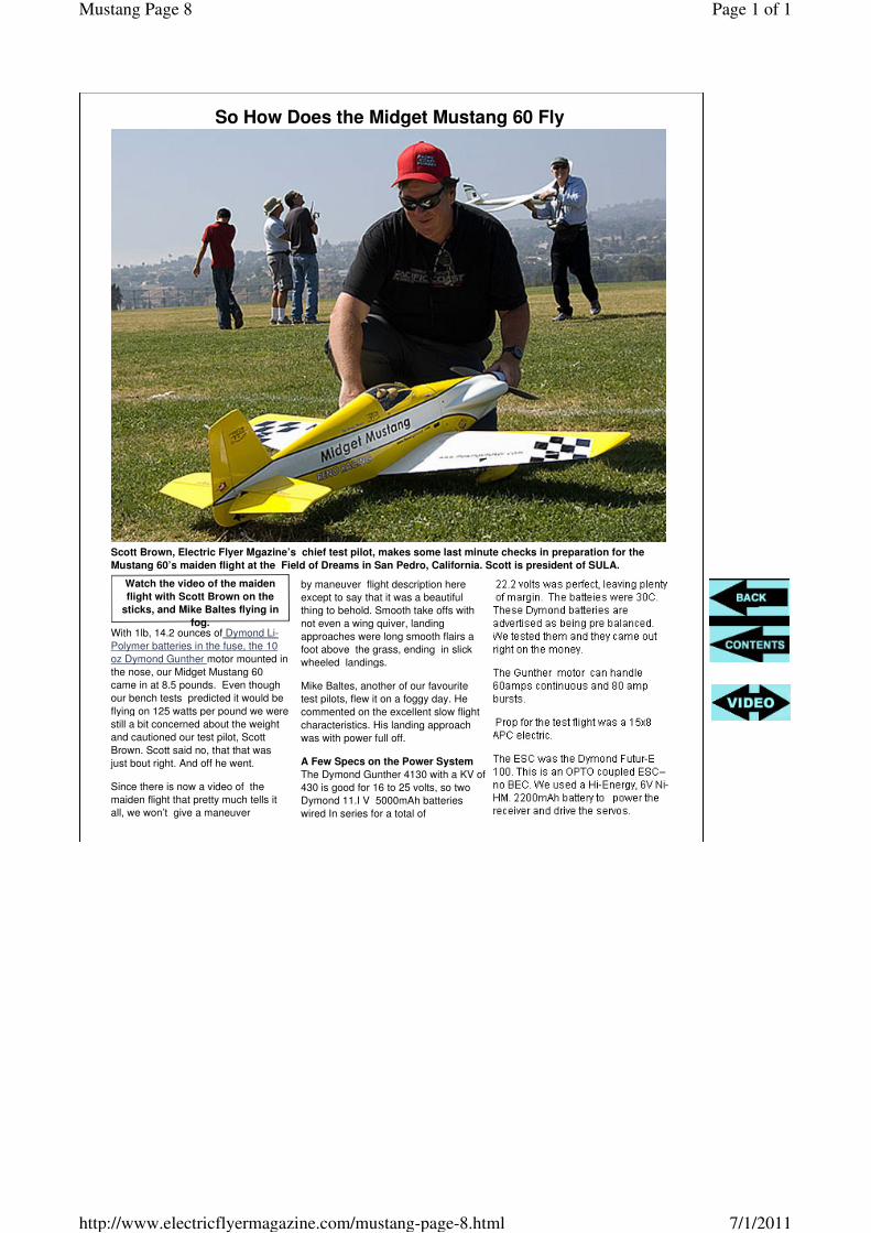
So How Does the Midget Mustang 60 Fly
Scott Brown, Electric Flyer Mgazine’s chief test pilot, makes some last minute checks in preparation for the
Mustang 60’s maiden flight at the Field of Dreams in San Pedro, California. Scott is president of SULA.
With 1lb, 14.2 ounces of Dymond Li-
Polymer batteries in the fuse, the 10
oz Dymond Gunther motor mounted in
the nose, our Midget Mustang 60
came in at 8.5 pounds. Even though
our bench tests predicted it would be
flying on 125 watts per pound we were
still a bit concerned about the weight
and cautioned our test pilot, Scott
Brown. Scott said no, that that was
just bout right. And off he went.
Since there is now a video of the
maiden flight that pretty much tells it
all, we won’t give a maneuver
Watch the video of the maiden
flight with Scott Brown on the
sticks, and Mike Baltes flying in
fog.
by maneuver flight description here
except to say that it was a beautiful
thing to behold. Smooth take offs with
not even a wing quiver, landing
approaches were long smooth flairs a
foot above the grass, ending in slick
wheeled landings.
Mike Baltes, another of our favourite
test pilots, flew it on a foggy day. He
commented on the excellent slow flight
characteristics. His landing approach
was with power full off.
A Few Specs on the Power System
The Dymond Gunther 4130 with a KV of
430 is good for 16 to 25 volts, so two
Dymond 11.I V 5000mAh batteries
wired In series for a total of
Page 1 of 1Mustang Page 8
7/1/2011http://www.electricflyermagazine.com/mustang-page-8.html