Embed Size (px)
Citation preview

ELECTRICAL SYSTEM
CONTENTS
CAUTIONS IN SERVICING 8- 2CONNECTOR 8- 2COUPLER 8- 2CLAMP 8- 2FUSE 8- 2SEMI-CONDUCTOR EQUIPPED PART 8- 3BATTERY 8- 3CONNECTING THE BATTERY 8- 3WIRING PROCEDURE 8- 3USING THE MULTI CIRCUIT TESTER 8- 4
LOCATION OF ELECTRICAL COMPONENTS 8- 5CHARGING SYSTEM 8- 7
TROUBLE SHOOTING 8- 7INSPECTION 8- 9
STARTER SYSTEM AND SIDE-STAND/IGNITION INTERLOCKSYSTEM 8-12
TROUBLE SHOOTING 8-12STARTER MOTOR REMOVAL AND DISASSEMBLY8-14STARTER MOTOR INSPECTION 8-15STARTER MOTOR REASSEMBLY 8-16STARTER RELAY INSPECTION 8-19SIDE-STAND/IGNITION INTERLOCK SYSTEM PARTSINSPECTION 8-20
IGNITION SYSTEM 8-23TROUBLESHOOTING 8-23INSPECTION 8-25
COMBINATION METER 8-29REMOVAL 8-29INSPECTION 8-32ENGINE COOLANT TEMPERATURE METER ANDINDICATOR 8-34
SPEED SENSOR 8-37REMOVAL 8-37INSTALLATION 8-37INSPECTION 8-38
LAMPS 8-39HEADLIGHT (SV650) 8-39HEADLIGHT (SV650S) 8-41BRAKE LIGHT/TAILLIGHT 8-43

ELECTRICAL SYSTEM 8-1
TURN SIGNAL LIGHTS 8-44RELAYS 8-45
TURN SIGNAL/SIDE-STAND RELAY 8-45STARTER RELAY 8-45FUEL PUMP RELAY 8-45
SWITCHES 8-46IGNITION SWITCH REMOVAL/INSTALLATION8-46INSPECTION 8-47
BATTERY 8-48SPECIFICATIONS 8-48INITIAL CHARGING 8-48SERVICING 8-50RECHARGING OPERATION 8-50
8

8-2 ELECTRICAL SYSTEM
CAUTIONS IN SERVICINGCONNECTOR•
When connecting a connector, be sure to push it in until aclick is felt .
•
Inspect the connector for corrosion, contamination and break-age in its cover .
COUPLER• With a lock type coupler, be sure to release the lock beforedisconnecting it and push it in fully till the lock works whenconnecting it.
•
When disconnecting the coupler, be sure to hold the coupleritself and do not pull the lead wires .
•
Inspect each terminal on the coupler for being loose or bent .•
Inspect each terminal for corrosion and contamination .
CLAMP•
Clamp the wire harness at such positions as indicated in"WIRE HARNESS ROUTING" . (r-79-14 to 9-16)
•
Bend the clamp properly so that the wire harness is clampedsecurely .
•
In clamping the wire harness, use care not to allow it to hangdown .
•
Do not use wire or any other substitute for the band typeclamp .
FUSE•
When a fuse blows, always investigate the cause, correct itand then replace the fuse .
•
Do not use a fuse of a different capacity .•
Do not use wire or any other substitute for the fuse .i

SEMI-CONDUCTOR EQUIPPED PART•
Be careful not to drop the part with a semi-conductor built insuch as a ECM .
•
When inspecting this part, follow inspection instruction strictly .Neglecting proper procedure may cause damage to this part .
BATTERY• The MF battery used in this motorcycle does not require main-tenance (e.g ., electrolyte level inspection, distilled waterreplenishment) .
•
During normal charging, no hydrogen gas is produced . How-ever, if the battery is overcharged, hydrogen gas may be pro-duced. Therefore, be sure there are no fire or spark sources(e .g ., short circuit) nearby when charging the battery .
•
Be sure to recharge the battery in a well-ventilated and openarea .
• Note that the charging system for the MF battery is differentfrom that of a conventional battery . Do not replace the MFbattery with a conventional battery .
CONNECTING THE BATTERY• When disconnecting terminals from the battery for disassem-bly or servicing, be sure to disconnect the O battery leadwire, first .
•
When connecting the battery lead wires, be sure to connectthe OO battery lead wire, first .
•
If the terminal is corroded, remove the battery, pour warmwater over it and clean it with a wire brush .
•
After connecting the battery, apply a light coat of grease to thebattery terminals .
•
Install the cover over the O battery terminal .
WIRING PROCEDURE•
Properly route the wire harness according to the "WIREROUTING" section . (C'9-14 to 9-16)
ELECTRICAL SYSTEM 8-3

8-4 ELECTRICAL SYSTEM
USING THE MULTI CIRCUIT TESTER• Properly use the multi circuit tester O and O probes .Improper use can cause damage to the motorcycle andtester .
•
If the voltage and current values are not known, begin mea-suring in the highest range .
•
When measuring the resistance, make sure that no voltage isapplied . If voltage is applied, the tester will be damaged .
•
After using the tester, be sure to turn the switch to the OFFposition .
CAUTION
Before using the multi circuit tester, read its instructionmanual .
J
j

LOCATION OF ELECTRICAL COMPONENTS
90 Battery•
Fuse box•
Side-stand/turn signal relay
•
Starter relay•
Fuel pump relay•
ECM (Engine Control Module)07 Ignition coil (No .1)
•
Fuel injector (P-74-42)•
STP sensor (r-74-38)
410 TP sensor (("74-28)11 STV actuator (174-37)© Generator13 CKP sensor14 Side stand switch15 Gear position switch16 Horn17 IAT sensor
ELECTRICAL SYSTEM 8-5

8-6 ELECTRICAL SYSTEM
90 ECT sensor ( r--~-4-31)
~2 IAP sensor (r7'4-25)03 Starter motor
® Oil pressure switch
O5 Fuel pump (['75-9)
© Cooling fan thermo-switch (F--76-9)O7 Cooling fan (r-76-8)© Ignition coil (No .2)
09 Regulator/rectifier7o PAIR control valve
14.

CHARGING SYSTEM
ELECTRICAL SYSTEM 8-7
Generator
L JRegulator/rectifier
1"~- ---~~~
-'7
Ignition switch1
1I 1O
1
A 1 A
Battery
1
a0J
Main fuse
TROUBLE SHOOTINGBattery runs down quicklyStep11) Check accessories which use excessive amounts of electricity .
Are accessories being installed?
YESNO
Remove accessories .Go to Step2 .
Step21) Check the battery for current leaks . (r-78-9)
Is the battery for current leaks OK?
Step31) Measure the charging voltage between the battery terminals . ( C-7'8-9)
Is the battery charging of voltage OK?
YES Go to Step3 .
NO •
Short circuit of wire harness .•
Faulty electrical equipment .
YES •
Faulty battery .•
Abnormal driving condition .NO Go to Step4 .

8-8 ELECTRICAL SYSTEM
Step41) Measure the continuity of the generator coil . (=8-10)
Is the resistance of generator coil OK?
Step51) Measure the generator no-load voltage . (r-78-1 0)
Is generator no-load performance OK?
YESNO
Go to Step6 .Faulty generator .
Step61) Inspect the regulator/rectifier . (r7-8-1 1)
Is the regulator/rectifier OK?
YESNO
Go to Step7 .Faulty regulator/rectifier .
Step71) Inspect the wire harness .
Is the wire harness OK?
Battery overchargesFaulty regulator/rectifier .Faulty battery .Poor contact of generator lead wire coupler .
1
LI
YES Go to Step5 .
NO •
Faulty generator coil .•
Disconnected lead wires .
YES Faulty battery
NO •
Short circuit of wire harness .•
Poor contact of coupler .

61. ~
INSPECTIONBATTERY CURRENT LEAKAGE•
Remove the front seat . (Cr7-4)
•
Turn the ignition switch to the OFF position .•
Disconnect the battery 8 lead wire .
Measure the current between O battery terminal and the 8 bat-
tery lead wire using the multi circuit tester . If the reading
exceeds the specified value, leakage is evident .
. . 09900-25008: Multi circuit tester set
•
Battery current (leak) : 3 mA and less
Tester knob indication : Current (-, 20 mA)
CAUTION
•
Because the current leak might be large, turn the
tester to high range first to avoid tester damage .
•
Do not turn the ignition switch to the "ON" position
when measuring current .
When checking to find the excessive current leakage, remove
the couplers and connectors, one by one, checking each part .
REGULATED VOLTAGE•
Remove the front seat . (r-_77-4) .
•
Start the engine and keep it running at 5 000 r/min . with the
dimmer switch turned HI position .
Measure the DC voltage between the +) and O battery termi-
nals using the multi circuit tester. If the voltage is not within the
specified value, inspect the generator and regulator/rectifier .
(=8-1 0 and 8-11)
NOTE:
When making this test, be sure that the battery is in fully-
charged condition .
. . 09900-25008 : Multi circuit tester set
7 1711 Tester knob indication : Voltage (-)
•
Charging output (Regulated voltage) :
14.0 - 15.5 V at 5 000 r/min .
ELECTRICAL SYSTEM 8-9

8-1 0 ELECTRICAL SYSTEM
GENERATOR COIL RESISTANCE•
Remove the seat tail cover . (fl77-5)•
Disconnect the generator coupler .
Measure the resistance between the three lead wires .If the resistance is out of the specified value, replace the statorwith a new one . Also, check that the generator core is insulatedproperly .
09900-25008: Multi circuit tester set
Tester knob indication : Resistance (S2)
•
Generator coil resistance : 0.2 - 0.7 S2 (Black - Black)- SZ (Black - Ground)
NOTE:When making above test, it is not necessary to remove the gen-erator.
GENERATOR NO-LOAD PERFORMANCE•
Remove the seat tail cover . (01'7-5)•
Disconnect the generator coupler .•
Start the engine and keep it running at 5 000 r/min .
Using the multi circuit tester, measure the voltage between threelead wires .If the tester reads under the specified value, replace the genera-tor with a new one .
09900-25008 : Multi circuit tester set
Tester knob indication : Voltage (-)•
Generator no-load performance :More than 60 V at 5 000 r/min (When engine is cold)
V

REGULATOR/RECTIFIER• Lift and support the fuel tank . (1'5-6)
•
Remove the air cleaner box . (C_~--5-16)
•
Disconnect the regulator/rectifier couplers .
Measure the voltage between the terminals using the multi cir-
cuit tester as indicated in the table below . If the voltage is not
within the specified value, replace the regulator/rectifier with a
new one .
.: 09900-25008: Multi circuit tester set
1711 Tester knob indication : Diode test (-W)
Unit: V
* More tham 1 .4 V (tester's battery voltage)
NOTE:
If the tester reads under 1 .4 V when the tester probes are not con-nected, replace its battery.
ELECTRICAL SYSTEM 8-11
O Tester probe
m B/R 131 B2 B3 B/W
o B/R 0.4 - 0.7 0 .4 - 0.7 0.4 - 0 .7 0 .5 - 1 .2
° 131 0 .4-0.7mn B2 * * 0 .4-0.7w
B3 * * * 0 .4-0.7O B/W * * * * \

8-12 ELECTRICAL SYSTEM
STARTER SYSTEM AND SIDE-STAND/IGNITION INTERLOCKSYSTEM
Engine stopswitch
Ignitionswitch
M
TROUBLE SHOOTINGMake sure that the fuses are not blown and the battery is fully-charged before diagnosing .
Starter motor will not run .Step11) Grasp the clutch lever, turn on the ignition switch with the engine stop switch in the "RUN" position and
side-stand switch in the "ON" position .2) Listen for a click from the starter relay when the starter button is pushed .
Is a click sound heard?
YESNO
Go to Step2 .Go to Step3 .
Step21) Check if the starter motor runs when its terminal is connected to the O battery terminal (Do not use a thin
wire because a large amount of current flows .)Does the starter motor run?
l .IYES
•••
Faulty starter relay .Loose or disconnected starter motor lead wire .Loose or disconnected between starter relay and O battery terminal .
NO Faulty starter motor .

i
ELECTRICAL SYSTEM 8-13
Step31) Measure the starter relay voltage at the starter relay connectors (between B/Y and Y/G) when the starter
button is pushed .Is a voltage OK?
Step41) Inspect the starter relay . (C P8-19)
Is the starter relay OK?
YESNO
Poor starter relay connection .Fa a v starter relay .
Step5The starter motor runs when the transmission is neutral with the side-stand up or down, but does not runwhen the transmission is in any position other than neutral with the side-stand down .1) Inspect the side-stand switch . (("78-20)
Is the side-stand switch OK?
Engine does not turn though the starter motor runs .Faulty starter clutch . ( C-73-82)
YES Go to Step4 .
NO
•
Faulty gear position switch .•
Faulty starter button .•
Faulty engine stop switch .•
Faulty turn signal/side-stand relay .•
Faulty ignition switch .•
Faulty clutch lever position switch .•
Faulty side-stand switch .•
Improper connector contact .•
Open circuit in wire harness .
YES •
Open circuit in wire harness .•
Poor contact of connector .NO •
Faulty side-stand switch .

8-14 ELECTRICAL SYSTEM
STARTER MOTOR REMOVAL ANDDISASSEMBLY•
Remove the starter motor and disconnect the starter motor
lead wire 90 .
•
Disassemble the starter motor as shown in the illustration .
1O Housing end (rear bracket)
® Terminal
OO Starter motor case
10 0-ring (2 pcs)
O2 Brush spring (2 pcs)
05 Washer
® Seal ring (2 pcs)
11 0-ring
O Brush holder66 Armature
O Washer
,12 Housing end (front bracket)
1

STARTER MOTOR INSPECTION
CARBON BRUSHInspect the brushes for abnormal wear, cracks, or smoothnessin the brush holder .If any damage is found, replace the brush assembly with a newone .
COMMUTATORInspect the commutator for discoloration, abnormal wear orundercut OA .If abnormal wear is found, replace the armature with a new one .If the commutator surface is discolored, polish it with #400 sandpaper and wipe it using a clean dry cloth .If there is no undercut, scrape out the insulator 1D with a sawblade .
ARMATURE COIL INSPECTIONCheck for continuity between each segment and between eachsegment and the armature shaft using the multi circuit tester .If there is no continuity between the segments or there is conti-nuity between the segments and shaft, replace the armaturewith a new one .:.
oe
09900-25008: Multi circuit tester set
Tester knob indication : Continuity test (•1 )))
OIL SEAL INSPECTIONCheck the oil seal lip for damage or leakage .If any damage is found, replace the housing end .
ELECTRICAL SYSTEM 8- 15
Segment

8-16 ELECTRICAL SYSTEM
STARTER MOTOR REASSEMBLYReassemble the starter motor in the reverse order of disassem-bly. Pay attention to the following points :
CAUTION
Replace the 0-rings with new ones to prevent oil leak-age and moisture .
•
Apply SUZUKI SUPER GREASE "A" to the lip of the oil seal .
99000-25030 : SUZUKI SUPER GREASE "A" (USA)99000-25010 : SUZUKI SUPER GREASE "A" (Others)
•
Apply a small quantity of SUZUKI MOLY PASTE to the arma-ture shaft .
99000-25140 : SUZUKI MOLY PASTE
•
Install the spacer 9) to brush terminal .
• When installing the brush holder on the rear bracket, set theprojection © of the brush holder into the groove ) of the rearbracket .

la
4V
•
Install the washers 02 (12 x 6 .5 x 2), washer ® (16 x 6.5 x 1),washer ® (14 x 6.5 x 1) and nut ($) .
CAUTION
Replace the 0-rings with new ones to prevent oil leak-age and moisture .
•
Install the washers © .
NOTE:The number of washer © varies according to individual .
•
Install the seal rings © to starter motor case O7 .•
When install the rear bracket to starter motor case, align themarks OA on the rear bracket with cut point © at the startermotor case .
CAUTION
Replace the seal rings with new ones to prevent oilleakage and moisture .
•
Install the washers © slip washer 0 and thrust stopper 11 .
NOTE:The number of washer ©9 varies according to individual .
•
Install the front bracket .•
Align the marks © on the front bracket with the marks © onthe starter motor case .
ELECTRICAL SYSTEM 8- 1 7

8-18 ELECTRICAL SYSTEM
•
Apply SUZUKI SUPER GREASE to the starter motor 0-rings .
99000-25030 : SUZUKI SUPER GREASE "A" (USA)99000-25010 : SUZUKI SUPER GREASE "A" (Others)
CAUTION
0 Starter motor housing bolt : 3.5 N.m (0.4 kgf-m 2.45 Ib-ft)
•
Install the starter motor .
•
First tighten the starter motor lower mounting bolt i , then
tighten the starter motor upper mounting bolt (W .
•
Connect the starter motor read wire as shown .
•
Tighten the nut 15 and fit the cap 16 .
19
Use new O-rings to prevent oil leakage .
*Tighten the starter motor housing bolts to the specified
torque .
1110 i~
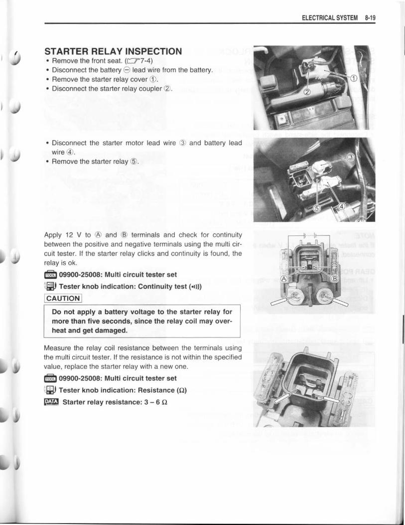
STARTER RELAY INSPECTION•
Remove the front seat . (('77-4)•
Disconnect the battery O lead wire from the battery .•
Remove the starter relay cover 1O .•
Disconnect the starter relay coupler C2) .
•
Disconnect the starter motor lead wire (3 and battery leadwire ® .
•
Remove the starter relay O5 .
Apply 12 V to OA and © terminals and check for continuitybetween the positive and negative terminals using the multi cir-cuit tester. If the starter relay clicks and continuity is found, therelay is ok .
. . 09900-25008 : Multi circuit tester set
Tester knob indication : Continuity test ( •) )))
CAUTION
Do not apply a battery voltage to the starter relay formore than five seconds, since the relay coil may over-heat and get damaged .
Measure the relay coil resistance between the terminals usingthe multi circuit tester . If the resistance is not within the specifiedvalue, replace the starter relay with a new one .
. . 09900-25008 : Multi circuit tester set
Tester knob indication : Resistance (S2)
[
Starter relay resistance : 3 - 6 S2
ELECTRICAL SYSTEM 8- 19

8-20 ELECTRICAL SYSTEM
SIDE-STAND/IGNITION INTERLOCKSYSTEM PARTS INSPECTIONCheck the interlock system for proper operation . If the interlock
system does not operate properly, check each component for
damage or abnormalities . If any abnormality is found, replace
the component with a new one .
SIDE-STAND SWITCH•
Lift and support the fuel tank with its prop stay . (['"'5-6)•
Disconnect the side-stand switch coupler and measure the
voltage between Green and Black/White lead wires .
09900-25008: Multi circuit tester set
Tester knob indication : Diode test (-W)
NOTE:
If the tester reads under 1 .4 V when the tester probes are notconnected, replace its battery.
GEAR POSITION SWITCH•
Lift and support the fuel tank with the fuel tank prop stay .
(=5-6)• Disconnect the gear position switch coupler and check the
continuity between Blue and Black/White with the transmis-sion in "NEUTRAL" .
09900-25008 : Multi circuit tester set
Tester knob indication : Continuity test (•~ )))
ON (Neutral)
OFF (Expect neutral)
CAUTION
Blue
0
Black/White
0
When disconnecting and connecting the gear position
switch coupler, make sure to turn OFF the ignition
switch, or electronic parts may get damaged .
Green
(OO probe)
Black/White
(0 probe)
Side-stand up 0.4 - 0.6 V
Side-stand down1 .4 V and more
(Tester's battery voltage)

l
•
Connect the gear position switch coupler to the wiring har-
ness .
•
Turn the ignition switch to "ON" position and side-stand to
upright position .
Measure the voltage between Pink and Black lead wires using
the multi circuit tester when shifting the gearshift lever from low
to top .
.: 09900-25008 : Multi circuit tester set
09900-25009 : Needle pointed probe set
Tester knob indication : voltage (V)
[
Gear position switch voltage
NOTE:* When connecting the multi circuit tester, use the needle
pointed probe to the back side of the lead wire coupler and
connect the probes of tester to them .
* Use a needle pointed probe outer diameter being below 0.5
mm to prevent the rubber of the waterproof coupler from dam-
age .
TURN SIGNAUSIDE-STAND RELAYThe turn signal/side-stand relay is composed of the turn signal
relay, side-stand relay and diode .
•
Remove the front seat. (=7-4)7-4)
•
Remove the fuse box cover .
•
Remove the fuse box from the rear fender .
ELECTRICAL SYSTEM 8-2 1
Gear
position1st 2nd 3rd 4th 5th 6th
Voltage Approx .1 .36V
Approx .
1 .77V
Approx .
2 .49V
Approx.
3.23V
Approx .
4.10V
Approx .
4.55V

8-22 ELECTRICAL SYSTEM
•
Remove the turn signal/Side-stand relay O .
SIDE-STAND RELAY INSPECTIONFirst check the insulation between 0 and © terminals with thetester. Then apply 12 V to terminals © and © (O to OD and O to©) and check the continuity between © and © . If there is nocontinuity, replace the turn signal/Side-stand relay with a newone .
. .
oe
09900-25008 : Multi circuit tester set
Tester knob indication: Continuity test ( •) l))
DIODE INSPECTIONMeasure the voltage between the terminals using the multi cir-cuit tester . Refer to the following table .
Unit: V
. .
0m ooa- U)
OI .2
©,
O Probe of tester to :
DA
0.4-0.6
A
More than 1 .4 V
09900-25008: Multi circuit tester set
~W Tester knob indication : Diode test (-W)
NOTE:If the multi circuit tester reads under 1 .4 V when the testerprobes are not connected, replace its battery .
SIDE-STAND RELAY •TURNDIODE
N E
j SIGNALRELAY8 0
0 © © © (F) 0
hB II
u i
1*

I
bo 'it
I GNITION SYSTEM
Throttlepositionsensor
Enginecoolant temp .sensor
Gearpositionswitch
m m
TROUBLESHOOTINGNo spark or poor spark
Make sure the engine stop switch is in the "RUN" position and side-stand is in up-right position . Make surethe fuse is not blown and the battery is fully-charged before diagnosing .
Step11) Check ignition system couplers for poor connections .
Is there connection in the ignition switch couplers?
ELECTRICAL SYSTEM 8-23
YESNO
Go to Step2 .Improper coupler connection .
Step 21) Measure the battery voltage between input lead wire (O/G and B/W) at the ECM with the ignition switch
in the "ON" position .Is the voltage OK?
J
YES Go to Step3 .• Faulty ignition switch .
NO • Faulty turn signal/Side-stand switch relay .• Faulty engine stop switch .• Broken wire harness or poor connection of related circuit couplers .
Engine stopo~
switch
ECM Side-
Ignition
°stand
° relayPowercircuit
source
CKPsensor
coilplug Fuse
taa o Spark
°pp
#1I Wave form0I
IDV, arrangementcircuit °oO 0
Ignitionswitch
CPU#2r
Fuse
T
Battery

8-24 ELECTRICAL SYSTEM
Step31) Measure the ignition coil primary peak voltage . (1'8-25)
NOTE:The ignition coil peak voltage inspection method is applicable only with the multi circuit tester and peak voltadaptor.
Is the peak voltage OK?
YESNO
Go to Step4 .Go to Step5 .
Step41) Inspect the spark plug . (=2-6)2-6)
Is the spark plug OK?
Steps1) Inspect the ignition coil . (=8-26)
Is the ignition coil OK?
Go to Step6 .YESNO Faulty i nition coil .
Step61) Measure the CKP sensor peak voltage and its resistance .
NOTE:The CKP sensor peak voltage inspection is applicable only with the multi circuit tester and peak volt adaptor .
Is the peak voltage and resistance OK?
1
_J
YES •
Improper spark plug connection .•
Go to Step5 .NO Faulty spark plug .
YES•••
Faulty ECM .Faulty wire harness .Improper ignition coupler connection .
NO Faulty CKP sensor .

i
INSPECTIONIGNITION COIL PRIMARY PEAK VOLTAGE•
Lift and support the fuel tank . (07-5-6)
•
Loosen the radiator lower mounting bolt and then swing the
radiator up .
•
Disconnect the two spark plug caps .
•
Connect new two spark plugs to each spark plug cap and
ground them .
•
Remove the air cleaner box .
NOTE:Make sure that all couplers and spark plugs are connected prop-
erly and the battery used is in fully-charged condition .
Measure the No.1 and No.2 ignition coils primary peak voltage
in the following procedure .
•
Connect the multi circuit tester with peak voltage adaptor as
follows .
No.1 ignition coil :
OO Probe: White/Blue terminal
•
Probe: Ground
No .2 ignition coil :
O Probe: Black terminal
•
Probe: Ground
NOTE:Do not disconnect the ignition coil primary wire coupler.
. . 09900-25008: Multi circuit tester set
CAUTION
Before using the multi circuit tester and peak voltadaptor, be sure to refer to the appropriate instruction
manual .
•
Shift the transmission into the neutral and then turn the igni-
tion switch to the "ON" position .
•
Pull the clutch lever .
• Press the starter button and allow the engine to crank for a
few seconds, and then measure the ignition coil primary peak
voltage .
ELECTRICAL SYSTEM 8-25

8-26 ELECTRICAL SYSTEM
•
Repeat the above procedure a few times and measure the
highest ignition coil primary peak voltage .
J Tester knob indication : Voltage (-)
•
Ignition coil primary peak voltage : 150 V and more
A WARNING
While testing, do not touch the tester probes and
spark plugs to prevent receiving an electric shock .
•
If the peak voltage is lower than the specified values, inspect
the ignition coil . (=8-26)
IGNITION COIL RESISTANCE•
Remove the fuel tank. (=5-6)
•
Disconnect the spark plug caps and coupler .
Measure the ignition coil resistance in both the primary and sec-
ondary windings . If the resistance is not within the standard
range, replace the ignition coil with a new one .
. . 09900-25008: Multi circuit tester set
(.011 Tester knob indication : Resistance (S2)
•
Ignition coil resistance
Primary
: 2 - 5 S ((O terminal - O terminal)
Secondary : 24 - 37 kS2, (Plug cap - (+ terminal)

CKP SENSOR PEAK VOLTAGE•
Remove the front seat . ( l"77-4)•
Disconnect the ECM coupler .
NOTE:Make sure that all of the couplers are connected properly andthe battery used is in fully-charged condition .
Measure the CKP sensor peak voltage in the following proce-dures .
•
Connect the multi circuit tester with peak volt adaptor as fol-lows .•
Probe: White lead wire•
Probe: Black/White lead wire
• 09900-25008 : Multi circuit tester set
FCAUTIONBefore using the multi circuit tester and peak voltadaptor, be sure to refer to the appropriate instructionmanual.
•
Shift the transmission into the neutral, and then turn the igni-tion switch to the "ON" position .
•
Pull the clutch lever .• Press the starter button and allow the engine to crank for afew seconds, and then measure the CKP sensor peak volt-age
•
Repeat the above procedure a few times and measure thehighest peak voltage .
Tester knob indication : Voltage (-)
[
CKP sensor peak voltage : 3 .7 V and more
If the peak voltage is lower than the specified values, check thepeak voltage at the CKP sensor lead wire coupler .
•
Remove the seat tail cover . (E i7-5)•
Disconnect the CKP sensor lead wire coupler and connect themulti circuit tester with the peak volt adaptor .•
Probe: Green lead wire•
Probe: Blue lead wire•
Measure the CKP sensor peak voltage at the CKP sensorlead wire coupler in the same manner as on the ECM coupler .
Tester knob indication : Voltage (-)
CKP sensor peak voltage : 3.7 V and more
ELECTRICAL SYSTEM 8-27

8-28 ELECTRICAL SYSTEM
If the peak voltage on the CKP sensor lead wire coupler is ok buton the ECM coupler is out of specification, the wire harnessmust be replaced . If both peak voltages are out of specification,the CKP sensor must be replaced and re-checked .
CKP SENSOR RESISTANCEMeasure the resistance between the lead wires and ground . Ifthe resistance is not specified value, the CKP sensor must bereplaced .
. • 09900-25008 : Multi circuit tester set
1 Tester knob indication : Resistance (0)
'
CKP sensor resistance : 130 - 240 92 (White - Green)S2 (White - Ground)
CKP sensorcoupler
G
'
wCKP sensor

I
L
COMBINATION METERREMOVAL(SV650S)•
Remove the cowling . (r-77-6)
•
Remove the combination meter .
NOTE:
"k" indicates hook location.
(SV650)•
Remove the headlight . (("77-29)
•
Remove the cover 90 .
•
Disconnect the combination meter coupler (Z .•
Remove the bracket (3 .
•
Remove the combination meter .
NOTE:" indicates hook location .
ELECTRICAL SYSTEM 8-29

8-30 ELECTRICAL SYSTEM
•
Disassemble the combination meter as shown in the illustration .
O Meter cover® Molding
OO Combination meter50 Cover
03 Housing

i
1.1
10 Meter cover OO Combination meter 03 Housing
ELECTRICAL SYSTEM 8-3 1

8-32 ELECTRICAL SYSTEM
INSPECTIONLED (LIGHT EMITTING DIODE)Check that the LED lights immediately after turning the ignitionswitch on .If the LED fails in operation, replace the combination meter unitwith a new one after checking its wire harness/coupler .
TACHOMETER• The tachometer pointer operates onetimes as shown below toreset tachometer pointer, when connecting the battery orcombination meter coupler .
1 . When the tachometer pointer is normal position .
2. When the tachometer pointer is top position .
NOTE:* This sweep motion is not performed when reconnecting coupler within 40 seconds .
•
If it do not operate correctly, check the wiring harness or replace combination meter with a new one .
it
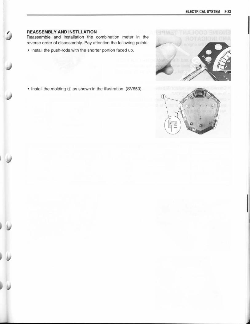
REASSEMBLY AND INSTILLATION IReassemble and installation the combination meter in the
reverse order of disassembly . Pay attention the following points .
•
Install the push-rods with the shorter portion faced up .
d
•
Install the molding ® as shown in the illustration . (SV650)
ELECTRICAL SYSTEM 8-33

8-34 ELECTRICAL SYSTEM
ENGINE COOLANT TEMPERATURE METERAND INDICATOR•
Disconnect the engine coolant temperature sensor coupler .
CAUTION
When connecting and disconnecting the engine cool-ant temp . sensor lead wire coupler, make sure to turnOFF the ignition switch, or electronic parts may getdamaged.
•
Connect the variable resistor WA between the terminals .•
Turn the ignition switch "ON" .• Check the display of engine coolant temperature meter asshown below. If any abnormality is found, replace the combi-nation meter with a new one .
Variable resister
Enginecoolanttemp.sensor
FI
12 ;
FI~ )\ x1000r/min ~~SEL `©
4' ~srsn mhFI ~J ~ l Of kmp/h
ODO iBBSC, lTRIP LI LI ~l LI LLLI1i1 •!1i1 i1i1/IoE1 LI •LI LI LI LI !
1'C
Water temperatureUnder 19 °C
(67 °F)Approx. 60 °C
(140 °F)120 - 129 °C(248 - 265 °F)
Over 130 °C(266 °F)
Resistance 2.45 kQ and more Approx. 0 .587 kQ 0 .1 kQ and less 0 QLCD © OFF OFF ON ONLCD © OFF OFF ON ON
LCD OD ---60
(140)120 - 129/Flicker(248 - 265/Flicker)
HI/Flicker

k
FUEL LEVEL SWITCH INSPECTION•
Remove the fuel pump assembly . (r-75-1 0)
• Connect 12 V battery f9 and test bulb (12 V, 3 .4 W) to the fuellevel switch as shown in the right illustrations . The bulb should
come on after several seconds if the switch is in good condi-tion .
• When the switch is immersed in water O under the above
condition, the bulb should go out. If the bulb remains lit,
replace the unit with a new one .
FUEL LEVEL INDICATOR•
Lift and support the fuel tank with the fuel tank prop stay .
(=5-6)5-6)•
Connect jumper wire between the Yellow/Black and Black/White lead wires at the wire harness .
•
Turn the ignition switch "ON" position and wait for approx . 5seconds .
Check the fuel level indicator lights .If not, replace the combination meter with a new one .
NOTE:After disconnecting the jump wire, it takes 30 seconds that thefuel level indicator comes off .
ELECTRICAL SYSTEM 8-35

8-36 ELECTRICAL SYSTEM
OIL PRESSURE INDICATOR
Before inspecting the oil pressure switch, check the engine oillevel . (r-_72-14)
•
Disconnect the oil pressure switch lead wire from the oil pres-sure switch .
•
Turn the ignition switch "ON" position .
Check the oil pressure indicator lights, when grounding the leadwire .If the oil pressure indicator does not come on, check the wiringharness or replace the combination meter with a new one .
1W
I
Vft
IV

SPEED SENSORREMOVALSV650•
Remove the headlight with two screws .
j
• Disconnect the speed sensor coupler.
SV650S•
Lift up and support the fuel tank . (=5-6)•
Remove the air cleaner box . (r-7-5-16)•
Disconnect the speed sensor coupler .
INSTALLATION•
Installation is in the reverse of removal .•
Connect the speed sensor coupler and check the wire har-ness routing . ( ("79-17)
ELECTRICAL SYSTEM 8-37

8-38 ELECTRICAL SYSTEM
INSPECTION•
Connect four 1 .5 V dry cells, 1 kQ resistance and the tester to
the speed sensor lead coupler as shown .
:. 09900-25008: Multi-circuit tester set
(W Tester knob indication : Voltage (=)
Lift and turn the front wheel and check that voltage varies be-
tween 0 - 6 V.
If any abnormal condition is noted, replace the sensor .
MAN nnUU V
MAN
i°- °°O
O/R
~ 0
0-B/w
0

0
LAMPS
HEADLIGHT (SV650)
O Rim 02 Reflector ©3 Bulb (60/50 W)
HEADLIGHT BEAM ADJUSTMENT•
Adjust the headlight beam, both vertical and horizontal .DA : Vertical adjuster
©: Horizontal adjuster
NOTE.
To adjust the headlight beam, adjust the beam horizontally first,
then adjust the vertically.
BULB REPLACEMENT•
Remove the headlight with two screws .
® Socket cover
ELECTRICAL SYSTEM 8-39
($ Bulb (5 W)

8-40 ELECTRICAL SYSTEM
•
Disconnect the coupler 90 .•
Disconnect the position light coupler (2) .
•
Remove the socket cover (1-
•
Unhook the bulb holder spring ® and pull out the bulb O5 .
CAUTION
If you touch the bulb with your bare hands, clean the
bulb with a cloth moistened with alcohol or soapy
water to prevent premature bulb failure .
•
Reassemble the bulb in the reverse order of removal .

J
Ij
HEADLIGHT (SV650S)
0 Headlight
O Position light
Headlight bulb
O : 12 V 60/55 WPosition light bulb O : 12 V 5 W
HEADLIGHT BEAM ADJUSTMENT•
Adjust the headlight beam, both vertical and horizontal .OA : Vertical adjuster© : Horizontal adjuster
NOTE:To adjust the headlight beam, adjust the beam horizontally first,then adjust the vertically .
ELECTRICAL SYSTEM 8-4 1

8-42 ELECTRICAL SYSTEM
BULB REPLACEMENT•
Disconnect the coupler and remove the rubber cap 02 .•
Remove the headlight bulb ® by unhooking the bulb holderspring (1 .
•
Reassemble the bulb in the reverse order of removal .

BRAKE LIGHT/TAILLIGHT
ELECTRICAL SYSTEM 8- 43
License lamp bulb ® : 12 V 5 W
The brake light/taillight is equipped LED. If LED fails in operation, replace the brake light/taillight as assem-bly .
1~ Brake light/taillight (2 License lamp O Bulb~A Brake light © Tail light C GND

8-44 ELECTRICAL SYSTEM
TURN SIGNAL LIGHTS
O Lens
02 Bulb
33 Bulb
Front turn signal light bulb 20 : . . . 12 V 21 WRear turn signal light bulb O :12 V 21 W
CAUTION
Do not overtighten the lens fitting screws .If you touch the bulb with your bare hands, clean the bulb with a cloth moistened with alcoholor soapy water to prevent premature bulb failure .

1j)RELAYSTURN SIGNAL/SIDE-STAND RELAYThe turn signal/side-stand relay is composed of the turn signalrelay, side-stand relay and diode .
INSPECTIONBefore removing the turn signal/side-stand relay, check theoperation of the turn signal light .If the turn signal light does not illuminate, inspect the bulb, turn
signal switch and circuit connection .If the bulb, turn signal switch and circuit connection are OK, theturn signal relay may be faulty; therefore, replace the turn signal/
side-stand relay with a new one .
NOTE:* Make sure that the battery is fully charged .* Refer to the page 8-22 for the side-stand relay and diodeinspection .
STARTER RELAY=8-19
FUEL PUMP RELAY=5-1 0
ELECTRICAL SYSTEM 8-45
® O
7
SIDE-STAND RELAY--------------
D_ LODE
TURN
SIGNAL
RELAY
4)

8-46 ELECTRICAL SYSTEM
SWITCHESIGNITION SWITCH REMOVAL/INSTALLATION•
Lift up and support the fuel tank . (C75-6)•
Remove the air cleaner box . (F-7 5-16)•
Disconnect the ignition switch coupler .
•
Remove the ignition switch mounting bolts using the specialtools .
09930-11920 : Torx bit JT40H09930-11940 : Bit holder
•
Install the ignition switch in the reverse order of removal .
.®
CAUTION
When reusing the ignition switch bolt, clean thread andapply the THREAD LOCK SUPER "1322" or THREADLOCK "1342" .
99000-32050 : THREAD LOCK "1342" (USA)
99000-32110: THREAD LOCK SUPER "1322" (Others)

i
0
INSPECTIONInspect each switch for continuity with a tester . If any abnormality is found, replace the respective switchassemblies with new ones .
IGNITION SWITCH
DIMMER SWITCH
TURN SIGNAL SWITCH
PASSING LIGHT SWITCH
ENGINE STOP SWICH
STARTER BUTTONColor
Position
PUSH
O/W
0
Y/G
0
HORN BUTTONColor
Position
PUSH
O/G B/W
HAZARD
FRONT BRAKE SWITCH
ColorPosition O/G W/13
OFFON 00
ColorPosition
B/Y B/Y
OFFON 0 0
REAR BRAKE SWITCH
CLUTCH LEVER POSITION SWITCH
OIL PRESSURE SWITCH
ELECTRICAL SYSTEM 8- 47
NOTE:Before inspecting the oil pressure switch, check theengine oil level . (r--72-14)
WIRE COLOR
B
: BlackBr : BrownGr : GrayLbI : Light blueLg : Light greenO : OrangeR : RedY
: YellowW : WhiteBI
: BlueG : Green
B/BI : Black with Blue tracerB/W : Black with White tracerB/Y : Black with Yellow tracerB/R : Black with Red tracerG/Y : Green with Yellow tracerO/B : Orange with Black tracerO/BI : Orange with Blue tracerO/G : Orange with Green tracerO/W : Orange with White tracerON : Orange with Yellow tracerW/B : White with Black tracerY/G : Yellow with Green tracer
ColorPosition R 0 ON Br
ON 0 00OFFLOCK
P 0 0
ColorPosition
W Y 0
HI (=D) 00LO (=D) 00
ColorPosition G/Y GroundON (engineis stopped) OO
OFF (engineis running)
ColorPosition ---- Lg Lbl B
L 00PUSH
R 00
ColorPosition O/B O/W
OFF (
)RUN (C))
ColorPosition B Lbl Lg
ON 0 00OFF
ColorPosition B/R 13/131
OFFON 0
ColorPosition 0 Y
PUSH 0

8-48 ELECTRICAL SYSTEM
BATTERYSPECIFICATIONS
Type designation
Capacity
YTX12 - BS
2'u' . 36 3 k:C (IG A-, , F R
INITIAL CHARGINGFilling electrolyte•
Remove the aluminum tape 10 sealing the battery electrolyte
filler holes .
NOTE:
When filling electrolyte, the battery must be removed from the
vehicle and must be put on the level ground.
•
Remove the caps 02 .NOTE:
* After filling the electrolyte completely, use the removed cap O2
as the sealed caps of battery-filler holes .* Do not remove or pierce the sealed areas OO of the electrolytecontainer.
• Insert the nozzles of the electrolyte container ® into the bat-
tery's electrolyte filler holes, holding the container firmly so
that it does not fall. Take precaution not to allow any of the
fluid to spill .
• Make sure air bubbles are coming up each electrolyte con-
tainer, and leave in this position for about more than 20 min-
utes .
of I>n I1
I
VIr
Jo °JO°
O
°°UU oQ0
Uo°
o 0 0UUO
0o°
Jo_)0
Vo
vU0UOUo°
° °0Uo°UGo
I

NOTE:
If no air bubbles are coming up from a filler port, tap the bottomof the electrolyte container two or three times .
Never remove the container from the battery .
• After confirming that the electrolyte has entered the batterycompletely, remove the electrolyte containers from the bat-
tery . Wait for about 20 minutes .
• Insert the caps ($ into the filler holes, pressing in firmly so thatthe top of the caps do not protrude above the upper surface of
the battery's top cover .
CAUTION
•
Never use anything except the specified battery .
•
Once install the caps to the battery ; do not remove
the caps .
•
Do not tap the caps with a hammer when installingthem .
For initial charging, use the charger specially designed for MF battery .
CAUTION
ELECTRICAL SYSTEM 8-49
•
For charging the battery, make sure to use the charger specially designed for MF battery. Other-wise, the battery may be overcharged resulting in shortened service life .
•
Do not remove the cap during charging .•
Position the battery with the cap facing upward during charging .

8-50 ELECTRICAL SYSTEM
SERVICINGVisually inspect the surface of the battery container. If any signsof cracking or electrolyte leakage from the sides of the battery
have occurred, replace the battery with a new one . If the batteryterminals are found to be coated with rust or an acidic white
powdery substance, then this can be cleaned away with sandpa-
per .
RECHARGING OPERATION
from the motorcycle .
* Do not remove the caps on the battery top while
recharging .
Recharging time: 1 .4 A for 5 to 10 hours or 6 A for one hour
CAUTION
Be careful not to permit the charging current toexceed 6 A at any time .
•
After recharging, wait for more than 30 minutes and check the
battery voltage with a multi circuit tester .
•
If the battery voltage is less than the 12 .5 V, recharge the bat-tery again .
•
If battery voltage is still less than 12 .5 V, after recharging,replace the battery with a new one .
•
When the motorcycle is not used for a long period, check the
battery every 1 month to prevent the battery discharge .
Charging period
0 10 20 30 40 50 60Time
(Minutes)
•
Using the multi circuit tester, check the battery voltage. If the (V)18
Stop charging
voltage reading is less than the 12 .0 V (DC), recharge the bat- 17
tery with a battery charger . 1615
CAUTION 1413
* 12When recharging the battery, remove the battery