Embed Size (px)
Citation preview
meltric.com
Electrical Safety Guide
Helping Employers Protect Workers from Arc Flash and other Electrical Hazards
Why an Effective Safety Program is Essential
National Safety Council statistics show that electrical injuries still occur in US industry with alarming frequency:
▼ 30,000 electrical shock accidents occur each year
▼ 1,000 fatalities due to electrocution occur each year
Recent studies also indicate that more than half of all fatal electrocutions occurred during routine construction, maintenance, cleaning, inspection or painting activities at industrial facilities. Although electrical shock accidents are frequent and electrocutions are the fourth leading cause of industrial fatalities, few are aware of how little current is actually required to cause severe injury or death. In this regard, even the current required to light just a 7 1/2 watt, 120 volt lamp is enough to cause a fatality – if it passes across a person’s chest.
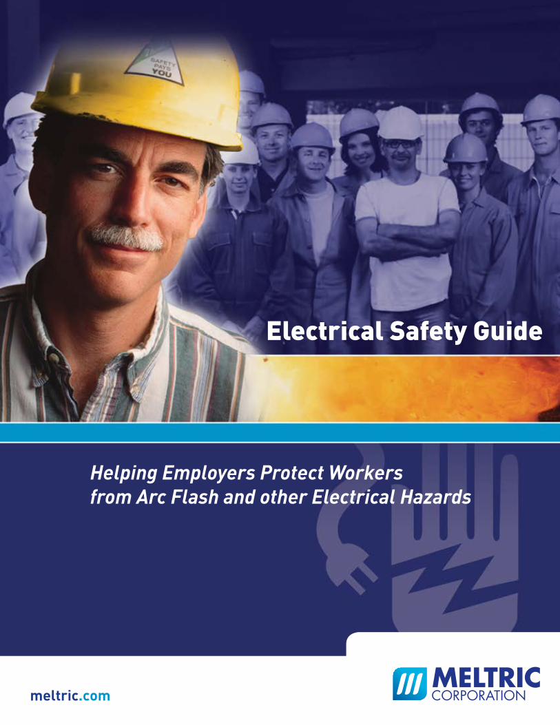
The arc flash and arc blasts that occur when short circuit currents flow through the air are violent and deadly events.
▼ Temperatures shoot up dramatically, reaching levels 4 times as hot as the sun’s surface and instantly vaporizing surrounding components.
▼ Ionized gases, molten metal from vaporized conductors and shrapnel from damaged equipment explode through the air under enormous pressure.
Anyone or anything in the path of an arc flash or arc blast is likely to be severely injured or damaged.
Statistics indicate that five to ten arc flash explosions occur in electrical equipment every day in the United States and that these accidents send more than 2,000 workers to burn centers with severe injuries each year.2
2 Capschell, Inc.
Electrical Shocks
2
Copper vapor instantly expands to 67,000 times the volume of copper
35,000°F temperatures cause severe burns
Thermoacoustic shock waves cause ruptured ear drums, collapsed lungs or other fatal injuries
Expelled shrapnel causes physical trauma
Blinding light causes vision damage
Consequences of an Arc Fault Event
The Hazards are Real
Arc Flash & Arc Blasts
When serious electrical accidents occur, the cost to a business often exceeds $1 million, and the cost to the injured person is immeasurable.
In 2010, OSHA issued almost 94,000 safety citations. Penalties for serious violations may be ten’s or even hundred’s of thousands of dollars, depending upon the situation.
In addition to the financial impacts of legal and settlement costs, the lost time and productivity disruptions caused by personal injury lawsuits can be a significant burden.
Injury Costs
OSHA Citations
Lawsuits
3
As an official act of Congress, the Occupational Safety and Health Act of 1970 is the law. Section 5(a) mandates that each employer shall:
1. Furnish to each of his employees employment and a place of employment which are free from recognized hazards that are causing or are likely to cause death or serious harm to his employees.
2. Comply with occupational safety and health standards promulgated under the act.
One of the key OSHA regulations that employers must comply with is 29 CFR 1910 ‘Occupational Safety & Health Standards.’ These standards establish the legal obligation requiring employers to proactively assess workplace hazards and take appropriate actions to advise and protect their employees from the hazards.
In situations where electrical injury has occurred, OSHA uses compliance with NFPA 70E as a key test in determining whether or not appropriate precautions have been taken. If they have not been, the employer may be subject to substantial fines and management personnel may be held criminally liable.
29 CFR 1910 – Occupational Safety & Health Standards
Key Electrical Safety Requirements
General requirements. – 1910.132
1910.132(d)(1) The employer shall assess the workplace to determine if hazards are present, or are likely to be present, which necessitate the use of personal protective equipment (PPE). If such hazards are present, or likely to be present, the employer shall:
1910.132(d)(1)(i)–(iii) Select, and have each affected employee use, the types of PPE that will protect the affected employee from the hazards identified in the hazard assessment; Communicate selection decisions to each affected employee; and, Select PPE that properly fits each affected employee.
1910.132(f)(1)(i) The employer shall provide training to each employee who is required by this section to use PPE.
Safeguards for personnel protection. – 1910.335
1910.335(a)(1)(i) Employees working in areas where there are potential electrical hazards shall be provided with, and shall use, electrical protective equipment that is appropriate for the specific parts of the body to be protected and for the work to be performed.
It’s Your Responsibility & It’s the Law
The Costs of Electrical Accidents can be Enormous
As the foremost consensus standard for electrical safety in the workplace, NFPA 70E is the primary resource for employers to use in determining how to comply with OSHA’s electrical safety regulations. It is also used by OSHA and the courts in workplace injury investigations to assess whether or not the involved employers took reasonable precautions to protect their employees.
The key elements of the standard are summarized below. Complete details should be obtained from the standard itself. In Canada, CSA published CSA Z462 ‘Workplace Electrical Safety’ which is based on and is harmonized with NFPA 70E. Key elements in CSA Z462 are essentially the same as those found in NFPA 70E.
Training Requirements
Employees who may be exposed to electrical hazards must be specifically trained to understand the hazards associated with electrical energy as well as the safety-related work practices and procedures required to provide protection from them. The level of training provided determines the tasks that an employee is qualified to perform. Only specially ‘Qualified Persons’ may perform work on or near exposed and energized electrical conductors or circuit parts. The training require-ments include:
▼ How to recognize the potential hazards that exist
▼ How to distinguish energized from non-energized parts
▼ How to determine the voltage of exposed energized electrical conductors
▼ The relationship between the hazard and potential injury
▼ How to avoid exposure to the hazards
▼ How to select appropriate personal protective equipment
▼ Specific work practices and procedures to be followed
▼ Emergency procedures for assisting victims of electrical incidents
▼ How to perform a hazard/risk analysis
▼ How to determine approach and flash protection boundaries
Electrical Safety Program
Employers are required to implement and document an electrical safety program to direct employee activities in a manner that is appropriate for the different voltage, energy level and circuit conditions that may be encountered. This safety program shall include all electrical safety procedures, be documented in writing, and be made available to all employees. If work
4
Key Elements of NFPA 70E®
The Standard for Electrical Safety in the Workplace
Article 110General Requirements for Electrical Safety–Related Work Practices
National Electric CodeSection 110.16 Flash ProtectionFPN No. 1:NFPA 70E-2009, Standard for Electrical Safety in the Workplace, provides assistance in determining the severity of potential exposure, planning safe work practices, and selecting personal protective equipment.
NFPA 70E is a registered trademark of the National Fire Protection Association, Quincy, MA 02169
on or near energized electrical conductors and circuit parts operating at 50V or more is required, the safety program must: ▼ Include a procedure that defines requirements and provides guidance for workers as they perform work on or near live parts.
▼ Identify the hazard/risk evaluation procedure to be used before work is started within the limited approach boundary of energized electrical conductors and circuit parts operating at 50 volts or more.
▼ Include a job briefing process to inform employees of the hazards, proper procedures, special precautions, energy source controls and PPE requirements.
Working While Exposed to Electrical Hazards
Safety work practices consistent with the nature and extent of the associated electrical hazards shall be used to safeguard employees from injury while working on or near exposed electrical or circuit parts that are or can become energized. Two primary conditions are identified and addressed:
(1) Energized Electrical Conductors and Circuit Parts – Safe Work Condition. Live parts to which an employee might be exposed shall be put into an electrically safe work condition before employees can work on or near them, unless work on energized components can be justified according to section 130.1.
(2) Energized Electrical Conductors and Circuit Parts – Unsafe Work Condition. Only qualified persons may work on electrical conductors or circuit parts that have not been put into an electrically safe work condition.
The requirements for establishing an electrically safe work condition are indicated in Article 120, while the requirements for work involving electrical hazards are covered in Article 130.
The most effective way to prevent an electrical injury is to completely remove the source of electrical energy and eliminate the possibility of its reappearance. To do so, workers must identify and disconnect all possible sources of electricity.
Process of Achieving an Electrically Safe Work Condition
(1) Identify all possible sources of electric supply. Care should be taken to identify the possible presence of secondary sources.
(2) Properly interrupt the load current(s) and open the disconnecting device(s). Not all disconnecting devices are rated to interrupt load currents; this should only
be done with a properly rated device.
(3) Verify deenergization through visual inspection of the disconnect contacts. Disconnecting means may sometimes fail to open all phase conductors when the
handle is operated, so it is necessary to verify physical contact separation. If this requires removing the disconnect door or cover, appropriate PPE must be used.
Article 120Establishing an Electrically Safe Work Condition
5
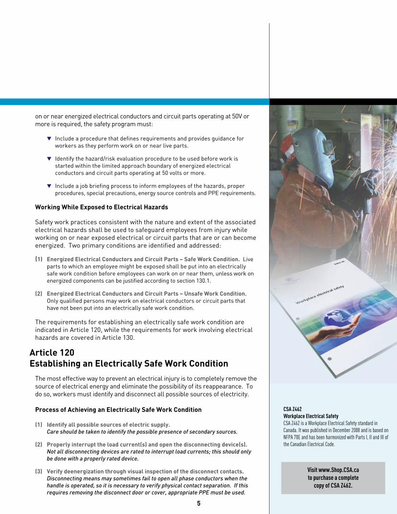
CSA Z462Workplace Electrical SafetyCSA Z462 is a Workplace Electrical Safety standard in Canada. It was published in December 2008 and is based on NFPA 70E and has been harmonized with Parts I, II and III of the Canadian Electrical Code.
Visit www.Shop.CSA.ca to purchase a complete
copy of CSA Z462.
Flash protection boundary
Limited approach boundary
Limited space
Any point on an exposed,energized electrical
conductor or circuit part
Restricted approach boundary
Restricted space
Prohibited approach boundary
Prohibited space
(4) Apply lockout/tagout devices. This should be done in accordance with a formally established company policy.
(5) Use a voltage detector to test each conductor to which the worker may be exposed in order to verify deenergization.
The voltage detecting device must be functionally tested both before and after taking the measurements in order to ensure that it is working satisfactorily.
(6) Circuit parts with induced voltages or stored electrical energy must be grounded. If the conductors being deenergized could contact other energized conductors or circuit parts, grounding devices rated for the available fault duty should be applied.
Justification
Deciding to work on or near energized electrical conductors and circuit parts should be a last resort in the workplace, after all other opportunities for establishing an electrically safe work condition have been exhausted. Work on energized parts at 50V or more should only be performed if the employer can demonstrate that deenergizing will introduce additional hazards or is not feasible due to equipment design or operational limitations.
When non-routine work must be performed on energized parts, a detailed work permit must be prepared before the work can start. The work permit must document the following elements and be approved by a responsible manager or safety officer:
▼ A description of the circuit and equipment to be worked on
▼ Justification for performing the work in an energized condition
▼A description of the safe work practices to be employed
▼Results of the shock hazard analysis
▼Determination of shock protection boundaries
▼Results of the flash hazard analysis
▼The flash protection boundary
▼The personnel protective equipment required for worker safety
▼Restricted access of unqualified persons from the work area
▼Evidence that the job briefing has been completed
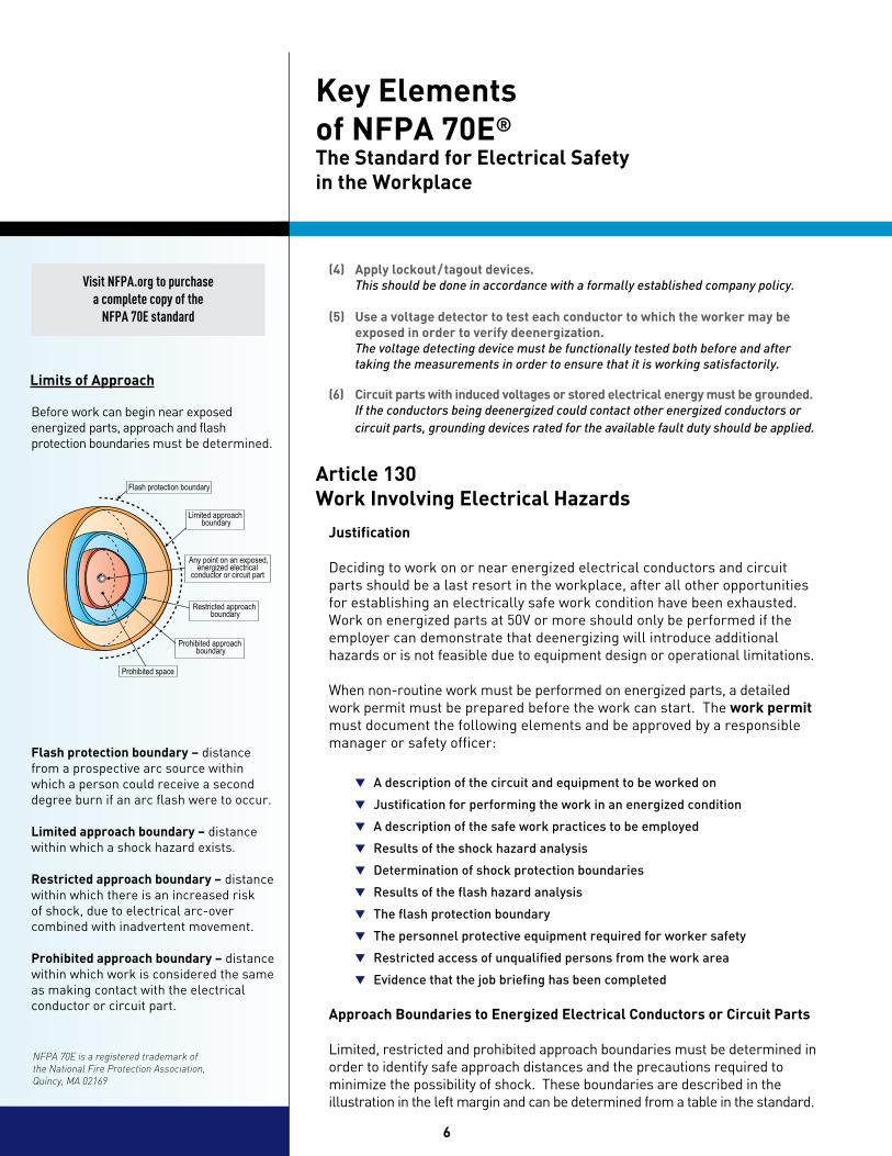
Approach Boundaries to Energized Electrical Conductors or Circuit Parts
Limited, restricted and prohibited approach boundaries must be determined in order to identify safe approach distances and the precautions required to minimize the possibility of shock. These boundaries are described in the illustration in the left margin and can be determined from a table in the standard.
6
Key Elements of NFPA 70E®
The Standard for Electrical Safety in the Workplace
Article 130Work Involving Electrical Hazards
Limits of Approach
Visit NFPA.org to purchase a complete copy of the
NFPA 70E standard
Flash protection boundary – distance from a prospective arc source within which a person could receive a second degree burn if an arc flash were to occur.
Limited approach boundary – distance within which a shock hazard exists.
Restricted approach boundary – distance within which there is an increased risk of shock, due to electrical arc-over combined with inadvertent movement.
Prohibited approach boundary – distance within which work is considered the same as making contact with the electrical conductor or circuit part.
Before work can begin near exposed energized parts, approach and flash protection boundaries must be determined.
NFPA 70E is a registered trademark of the National Fire Protection Association, Quincy, MA 02169
Arc Flash Hazard Analysis
An arc flash hazard analysis shall be done in order to protect personnel from the possibility of being injured by an arc flash. As part of this analysis, flash protection boundaries must be determined based on available bolted fault currents and the incident energy exposure level for personnel working within this boundary must be calculated.
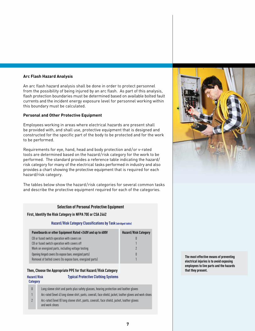
Personal and Other Protective Equipment
Employees working in areas where electrical hazards are present shall be provided with, and shall use, protective equipment that is designed and constructed for the specific part of the body to be protected and for the work to be performed.
Requirements for eye, hand, head and body protection and/or v-rated tools are determined based on the hazard/risk category for the work to be performed. The standard provides a reference table indicating the hazard/risk category for many of the electrical tasks performed in industry and also provides a chart showing the protective equipment that is required for each hazard/risk category. The tables below show the hazard/risk categories for several common tasks and describe the protective equipment required for each of the categories.
Then, Choose the Appropriate PPE for that Hazard / Risk Category
Hazard / Risk Typical Protective Clothing Systems Category
0 Long sleeve shirt and pants plus safety glasses, hearing protection and leather gloves
1 Arc-rated (level 4) long sleeve shirt, pants, coverall, face shield, jacket, leather gloves and work shoes
2 Arc-rated (level 8) long sleeve shirt, pants, coverall, face shield, jacket, leather gloves and work shoes
7
First, Identify the Risk Category in NFPA 70E or CSA Z462
Hazard / Risk Category Classifications by Task (abridged table)
Selection of Personal Protective Equipment
Panelboards or other Equipment Rated >240V and up to 600V Hazard / Risk Category
CB or fused switch operation with covers on 0 CB or fused switch operation with covers off 1 Work on energized parts, including voltage testing 2
Opening hinged covers (to expose bare, energized parts) 0 Removal of bolted covers (to expose bare, energized parts) 1
The most effective means of preventing electrical injuries is to avoid exposing employees to live parts and the hazards that they present.
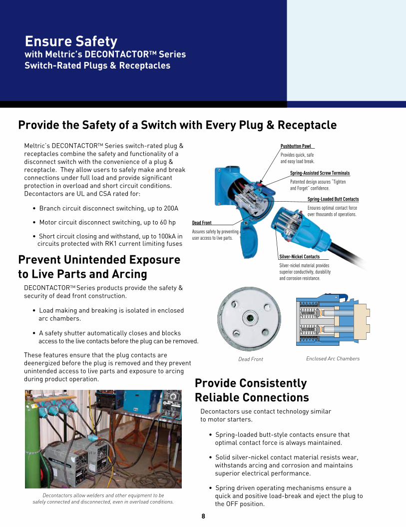
Decontactors use contact technology similar to motor starters.
• Spring-loaded butt-style contacts ensure that optimal contact force is always maintained.
• Solid silver-nickel contact material resists wear, withstands arcing and corrosion and maintains superior electrical performance.
• Spring driven operating mechanisms ensure a quick and positive load-break and eject the plug to the OFF position.
Meltric’s DECONTACTORTM Series switch-rated plug & receptacles combine the safety and functionality of a disconnect switch with the convenience of a plug & receptacle. They allow users to safely make and break connections under full load and provide significant protection in overload and short circuit conditions. Decontactors are UL and CSA rated for:
• Branch circuit disconnect switching, up to 200A
• Motor circuit disconnect switching, up to 60 hp
• Short circuit closing and withstand, up to 100kA in circuits protected with RK1 current limiting fuses
Provide the Safety of a Switch with Every Plug & Receptacle
8
DECONTACTORTM Series products provide the safety & security of dead front construction.
• Load making and breaking is isolated in enclosed arc chambers.
• A safety shutter automatically closes and blocks access to the live contacts before the plug can be removed.
These features ensure that the plug contacts are deenergized before the plug is removed and they prevent unintended access to live parts and exposure to arcing during product operation.
Ensure Safetywith Meltric’s DECONTACTORTM Series Switch-Rated Plugs & Receptacles
Provide Consistently Reliable Connections
Spring-Loaded Butt Contacts
Ensures optimal contact force over thousands of operations.
Spring-Assisted Screw Terminals
Patented design assures “Tighten and Forget” confidence.
Silver-Nickel Contacts
Silver-nickel material provides superior conductivity, durability and corrosion resistance.
Dead Front
Assures safety by preventing user access to live parts.
Pushbutton Pawl
Provides quick, safe and easy load break.
Decontactors allow welders and other equipment to be safely connected and disconnected, even in overload conditions.
Prevent Unintended Exposureto Live Parts and Arcing
Dead Front Enclosed Arc Chambers
9
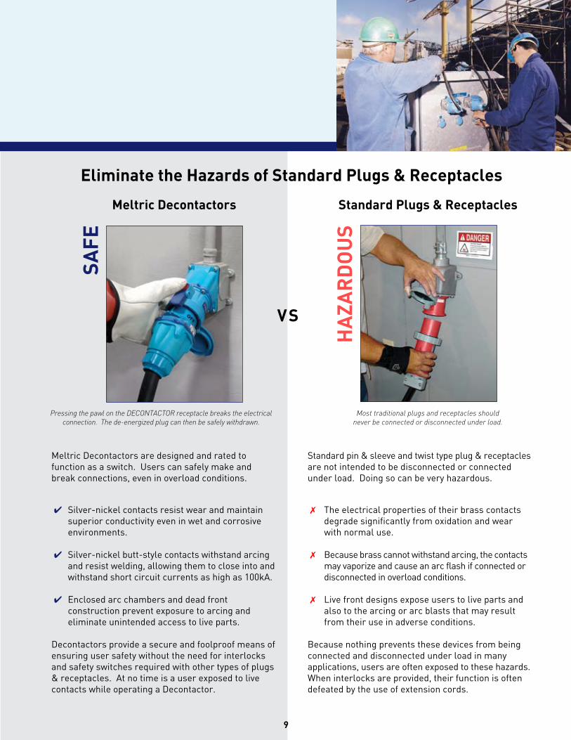
Meltric Decontactors are designed and rated to function as a switch. Users can safely make and break connections, even in overload conditions.
✔ Silver-nickel contacts resist wear and maintain superior conductivity even in wet and corrosive environments.
✔ Silver-nickel butt-style contacts withstand arcing and resist welding, allowing them to close into and withstand short circuit currents as high as 100kA.
✔ Enclosed arc chambers and dead front construction prevent exposure to arcing and eliminate unintended access to live parts.
Decontactors provide a secure and foolproof means of ensuring user safety without the need for interlocks and safety switches required with other types of plugs & receptacles. At no time is a user exposed to live contacts while operating a Decontactor.
Standard pin & sleeve and twist type plug & receptacles are not intended to be disconnected or connected under load. Doing so can be very hazardous.
✗ The electrical properties of their brass contacts degrade significantly from oxidation and wear with normal use.
✗ Because brass cannot withstand arcing, the contacts may vaporize and cause an arc flash if connected or disconnected in overload conditions.
✗ Live front designs expose users to live parts and also to the arcing or arc blasts that may result from their use in adverse conditions.
Because nothing prevents these devices from being connected and disconnected under load in many applications, users are often exposed to these hazards. When interlocks are provided, their function is often defeated by the use of extension cords.
Eliminate the Hazards of Standard Plugs & Receptacles
Standard Plugs & ReceptaclesMeltric Decontactors
Pressing the pawl on the DECoNtACtor receptacle breaks the electrical connection. the de-energized plug can then be safely withdrawn.
Most traditional plugs and receptacles should never be connected or disconnected under load.
SAFE
VS
HA
ZAR
DO
US
Simplify NFPA 70E® Compliancewith Meltric’s DECONTACTORTM Series Switch Rated Plugs & Receptacles
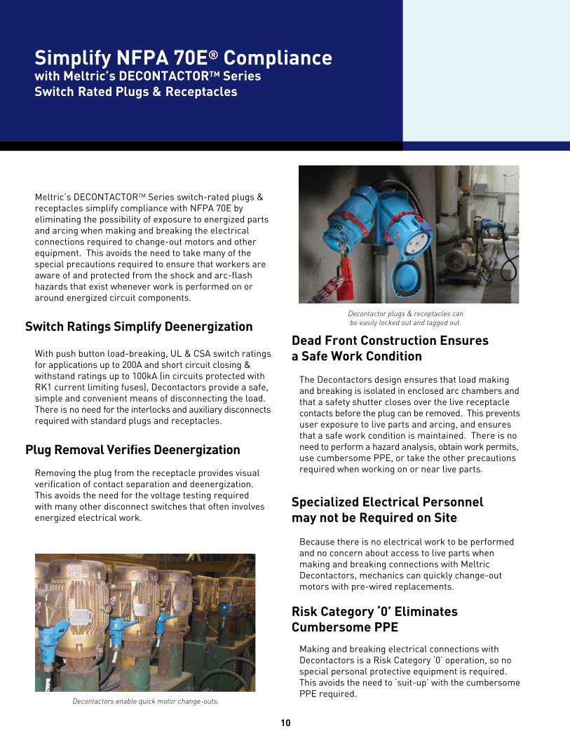
Meltric’s DECONTACTORTM Series switch-rated plugs & receptacles simplify compliance with NFPA 70E by eliminating the possibility of exposure to energized parts and arcing when making and breaking the electrical connections required to change-out motors and other equipment. This avoids the need to take many of the special precautions required to ensure that workers are aware of and protected from the shock and arc-flash hazards that exist whenever work is performed on or around energized circuit components.
With push button load-breaking, UL & CSA switch ratings for applications up to 200A and short circuit closing & withstand ratings up to 100kA (in circuits protected with RK1 current limiting fuses), Decontactors provide a safe, simple and convenient means of disconnecting the load. There is no need for the interlocks and auxiliary disconnects required with standard plugs and receptacles.
Removing the plug from the receptacle provides visual verification of contact separation and deenergization. This avoids the need for the voltage testing required with many other disconnect switches that often involves energized electrical work.
The Decontactors design ensures that load making and breaking is isolated in enclosed arc chambers and that a safety shutter closes over the live receptacle contacts before the plug can be removed. This prevents user exposure to live parts and arcing, and ensures that a safe work condition is maintained. There is no need to perform a hazard analysis, obtain work permits, use cumbersome PPE, or take the other precautions required when working on or near live parts.
Because there is no electrical work to be performed and no concern about access to live parts when making and breaking connections with Meltric Decontactors, mechanics can quickly change-out motors with pre-wired replacements.
Making and breaking electrical connections with Decontactors is a Risk Category ‘0’ operation, so no special personal protective equipment is required. This avoids the need to ‘suit-up’ with the cumbersome PPE required.
Switch Ratings Simplify DeenergizationDead Front Construction Ensures a Safe Work Condition
Specialized Electrical Personnel may not be Required on Site
Risk Category ‘0’ Eliminates Cumbersome PPE
Plug Removal Verifies Deenergization
10
Decontactors enable quick motor change-outs.
Decontactor plugs & receptacles can be easily locked out and tagged out.
11
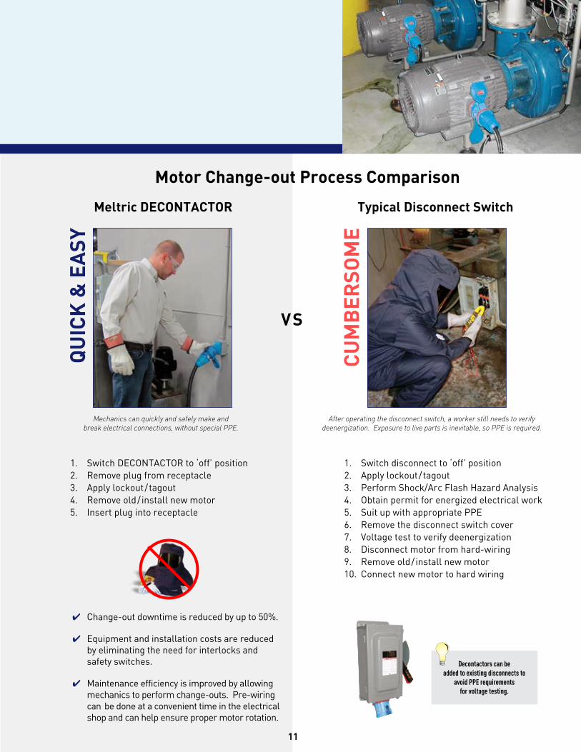
1. Switch DECONTACTOR to ‘off’ position2. Remove plug from receptacle3. Apply lockout/tagout4. Remove old/ install new motor5. Insert plug into receptacle
✔ Change-out downtime is reduced by up to 50%.
✔ Equipment and installation costs are reduced by eliminating the need for interlocks and safety switches.
✔ Maintenance efficiency is improved by allowing mechanics to perform change-outs. Pre-wiring can be done at a convenient time in the electrical shop and can help ensure proper motor rotation.
1. Switch disconnect to ‘off’ position2. Apply lockout/tagout3. Perform Shock/Arc Flash Hazard Analysis4. Obtain permit for energized electrical work 5. Suit up with appropriate PPE6. Remove the disconnect switch cover7. Voltage test to verify deenergization8. Disconnect motor from hard-wiring9. Remove old/ install new motor10. Connect new motor to hard wiring
Mechanics can quickly and safely make and break electrical connections, without special PPE.
After operating the disconnect switch, a worker still needs to verify deenergization. Exposure to live parts is inevitable, so PPE is required.
VS
QU
ICK
& E
ASY
CU
MB
ERSO
ME
Motor Change-out Process Comparison
Typical Disconnect SwitchMeltric DECONTACTOR
Decontactors can be added to existing disconnects to
avoid PPE requirements for voltage testing.
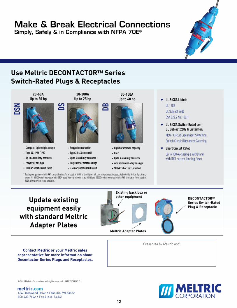
▼ UL & CSA Listed: UL 1682
UL Subject 2682
CSA C22.2 No. 182.1
▼ UL & CSA Switch-Rated per UL Subject 2682 & Listed for: Motor Circuit Disconnect Switching
Branch Circuit Disconnect Switching
▼ Short Circuit Rated Up to 100kA closing & withstand with RK1 current limiting fuses
Use Meltric DECONTACTORTM Series Switch-Rated Plugs & Receptacles
Contact Meltric or your Meltric sales representative for more information about Decontactor Series Plugs and Receptacles.
Presented by Meltric and:
Existing back box or other equipment
Meltric Adapter Plates
DECONTACTORTM Series Switch-Rated Plug & Receptacle
20-60AUp to 20 hp
20-200AUp to 25 hp
30-100AUp to 60 hp
• Compact, lightweight design
• Type 4X, IP66 / IP67
• Up to 4 auxiliary contacts
• Polyester casings
• 100kA+ short circuit rated
• Rugged construction
• Type 3R (4X optional)
• Up to 6 auxiliary contacts
• Polyester or Metal casings
• ≥65kA+ short circuit rated
• High horsepower capacity
• IP67
• Up to 4 auxiliary contacts
• Zinc aluminum alloy casings
• 100kA+ short circuit rated
Update existing equipment easily
with standard Meltric Adapter Plates
DSN DS DB
Make & Break Electrical ConnectionsSimply, Safely & in Compliance with NFPA 70E®
+ Testing was performed with RK1 current limiting fuses sized at 400% of the highest full load motor ampacity associated with the devices hp ratings, except for DB100 which was tested with 250A fuses. Non-horsepower rated DS100 and DS200 devices were tested with RK5 time delay fuses sized at 100% of the devices rated ampacity.
meltric.com4640 Ironwood Drive • Franklin, WI 53132800.433.7642 • Fax 414.817.6161
© 2013 Meltric Corporation. All rights reserved. SAFETYGUIDE E
12