Embed Size (px)
Citation preview

SECTION IIMODEL 750 AIRPLANE AND SYSTEMS
ELECTRICALGENERAL
Electrical power is made available through the use of batteries, DC power generators, anAuxiliary Power Unit (APU) located in the tail section, and two engine driven alternators (whichprovide AC power). The battery system uses two, twenty cell, 44 ampere-hour nickelcadmium or the optional lead-acid batteries. There are two brushless engine-drivengenerators that provide DC power (rated at 400 amperes up to 41,000 feet and 300 amperesabove 41,000 feet). DC power is controlled by the use of two generator control units (GCUs).AC power, which is used only for the windshield anti-ice system, is generated by two engine-driven, three phase, 115/200 volt, three kilovolt-ampere (KVA) alternators (having a variablefrequency of 200-400 cycles, depending on engine speed) controlled by an two altenratorcontrol units.. The 400 ampere on-board Auxiliary Power Unit (APU) provides DC electricalpower and is equipped with its own DC ammeter, providing current drain information to theflight crew. The APU can be started and used up to an altitude of 31,000 feet.
Two battery ON-OFF switches and an emergency (EMER) switch provide power to theelectrical system when battery power is desirable or in the event of a generator failure.
A Ground Power Unit (GPU) receptacle facilitates use of a GPU. Power from a GPU ismade available by the external power switch located in the cockpit.
DIRECT CURRENT (DC) POWER
DC power required to operate the airplane and all DC operated equipment is provided bythe engine-driven generators, the dual battery installation, and the on board auxiliary powerunit (APU). Generator power is selected by the LH and RH GEN switches and the APUGENERATOR switch. In the LH GEN, RH GEN or APU ON position, the GCUs will place therespective generator on line when the engines or APU are running. The left and right enginegenerators operate independently. There is no load paralleling. The APU generator will notcome on line or will drop off line if the right engine generator is on line. The reset switchposition is momentary and resets the GCU after a system trip has occurred. The left andright generators supply 28.5 VDC power to the RH feed bus through the RH isolation relay, tothe RH battery bus through the crosstie relay and the LH isolation relay, to the LH battery bus.
DIRECT CURRENT (DC) POWER INDICATORS
The voltage and amperage of the engine-driven DC generators can be read on the crewalerting system (CAS) section of the EICAS display unit. In order to read the information, theELEC bezel button must be depressed. The voltage and amperage of both generators andthe temperature of both batteries may be then read simultaneously. Eight different digitalEICAS messages may be annunciated to apprise the crew of abnormal electrical systemoperation. The ELEC bezel button can then be pressed to read the specific system condition.The APU has its own ammeter which is located on the copilot's meter panel.
Unless the ELEC bezel button is depressed, routine monitoring of the electrical system isnot available, however, any abnormal condition will be presented on the EICAS display as ared, amber, or cyan digital message. When a red message appears, the message will alsoappear on the cross-side multifunction display (MFD) and the master warning. The messagewill flash until it is acknowledged. An amber message will cause the master caution light toilluminate steadily, and the message will flash until it is acknowledged. Cyan advisorymessages will appear and flash for five seconds then annunciate steadily. The messageswhich can be presented are: BATT 1-2 O'TEMP (red), GEN OFF L-R (red or amber,depending on whether 1 or 2 generators have failed), BUS CTRL 1-2 FAIL (amber), BUS ISOOPEN L-R (amber), REMOTE CB TRIPPED (cyan), and DC BEARING L-R-APU (cyan).
75OMA-00 Configuration AA 2-93

SECTION IIAIRPLANE AND SYSTEMS MODEL 750
� � � � � � � � � � � � � � � � � � � � � � � � � � � � � � � � � � � � � � � � � � � � � � � � � � � � � � � � � � � � � � � � � � � � � � � � � � � � � � � � � � � � � � � � � � � � � � � � � � � � � � � � � � � � � � � � � � � � � � � � � � � � � �
� � � � � � � � � � � � � � � � � � � � � � � � � � � � � � � � � � � � � � � � � � � � � � � � � � � � � � � � � � � � � � � � � � � � � � � � � � � � � � � � � � � � � � � � � � � � � � � � � � � � � � � � � � � � � � � � � � � � � � � � � � � � � �
� � � � � � � � � � � � � � � � � � � � � � � � � � � � � � � � � � � � � � � � � � � � � � � � � � � � � � � � � � � � � � � � � � � � � � � � � � � � � � � � � � � � � � � � � � � � � � � � � � � � � � � � � � � � � � � � � � � � � � � � � � � � � �
� � � � � � � � � � � � � � � � � � � � � � � � � � � � � � � � � � � � � � � � � � � � � � � � � � � � � � � � � � � � � � � � � � � � � � � � � � � � � � � � � � � � � � � � � � � � � � � � � � � � � � � � � � � � � � � � � � � � � � � � � � � � � �
Figure 2-34 Electrical Block Diagram and Power Distribution (Sheet 1 of 3)
� � � � � � � � � � � � � � � � � � � � � � � � � � � � � � � � � � � � � � � � � � � � � � � � � � � � � � � � � � � � � � � � � � � � � � � � � � � � � � � � � � � � � � � � � � � � � � � � � � � � � � � � � � � � � � � � � � � � � � � � � � � � � �
� � � � � � � � � � � � � � � � � � � � � � � � � � � � � � � � � � � � � � � � � � � � � � � � � � � � � � � � � � � � � � � � � � � � � � � � � � � � � � � � � � � � � � � � � � � � � � � � � � � � � � � � � � � � � � � � � � � � � � � � � � � � � �
� � � � � � � � � � � � � � � � � � � � � � � � � � � � � � � � � � � � � � � � � � � � � � � � � � � � � � � � � � � � � � � � � � � � � � � � � � � � � � � � � � � � � � � � � � � � � � � � � � � � � � � � � � � � � � � � � � � � � � � � � � � � � �
� � � � � � � � � � � � � � � � � � � � � � � � � � � � � � � � � � � � � � � � � � � � � � � � � � � � � � � � � � � � � � � � � � � � � � � � � � � � � � � � � � � � � � � � � � � � � � � � � � � � � � � � � � � � � � � � � � � � � � � � � � � � � �
� � � � � � � � � � � � � � � � � � � � � � � � � � � � � � � � � � � � � � � � � � � � � � � � � � � � � � � � � � � � � � � � � � � � � � � � � � � � � � � � � � � � � � � � � � � � � � � � � � � � � � � � � � � � � � � � � � � � � � � � � � � � � �
� � � � � � � � � � � � � � � � � � � � � � � � � � � � � � � � � � � � � � � � � � � � � � � � � � � � � � � � � � � � � � � � � � � � � � � � � � � � � � � � � � � � � � � � � � � � � � � � � � � � � � � � � � � � � � � � � � � � � � � � � � � � � �
ELECTRICAL SYSTEM BLOCK DIAGRAM
2-94 Configuration AA 75OMA-00

SECTION IIMODEL 750 AIRPLANE AND SYSTEMS
ELECTRICAL SYSTEM (Continued)
Figure 2-34 Electrical Block Diagram and Power Distribution (Sheet 2)
75OMA-00 Configuration AA 2-95

SECTION IIAIRPLANE AND SYSTEMS MODEL 750
ELECTRICAL SYSTEM (Continued)
LEFT MAIN
L LANDING LIGHTCOCKPIT ECU GRD RECOG LIGHTSIRS 1 (primary)L FAIRING HTFLAPSIRS 2 AUXEICAS
IAC 1MFD 1EICAS DISPDAU 1 / 2 ADISP CONT 1
LEFT BATT
ENTRY LIGHTSBATT SENSE 1
LEFT EMER L START LOGICAUX PANEL LTSL W/S A/I CONTL BLD PRECOOLERSEC STAB TRIMAILERON TRIMPITCH FEELUPPER RUD/YAW DAMP ARUD LIMIT ABAT 1 AMMETERWARN AUDIO 1COM / NAV / RMU 1TRANSPONDER 1 (opt)
STANDBY HSIIRS 1 AUXL FIRE DET / EXTL F/W SHUTOFFL & R FADEC AL EMER LTSAUDIO AMP 1MADC 1L. FUEL PUMP
LEFT HAND DISTRIBUTION RIGHT HAND DISTRIBUTION
RIGHT MAIN
R. LANDING LTTAXI LTSCAB ECU (PAC)BAG FANR. FAIRING HTSTBY INST (primary)STBY BAT (charge)IRS 2 (primary)RIGHT BATT
BATT SENSE 2
APU
APU PWR / SENSEAPU ECUAPU FIRE
RIGHT EMER
R START LOGICUPPER RUD/YAW DAMP BR BLD PRECOOLERHF 1AUDIO AMP 2AUDIO WARN 2MADC 2R EMER LTSSTBY P/S HTRUD TRIMLDG GEARRUD LIM BA AUX HYD PUMPR FIRE DET / EXTR FIREWALL SHUTOFFL & R FADEC BBAT 2 AMMETER
RIGHT EXTENSION
MAP LTSR W/S A/I CONTR RAT, P/S, AOA HTR A/I (valves fail open)PRI STAB TRIMR FUEL BOOSTF FUEL TRANSFER (fails current position)R START VALVER FUEL QTYR TLA DISCRETESR STALL WARN / AOANOSE STEERINGR TR (deploy & stow)HYD CONT B (Fails on)PCU MONISOTRUD STBY HYDCOM / NAV / RMI 2TRANSPONDER 2ADF 2DME 2HF 2GPS / FMS 2AP / FGC BPFD / MFD 2DISP CONT 2DAU 2 BNAV LTSR & CTR PANEL LTS
STANDBY BUS
STBY ALT/AS VIBSTBY ATT INDICATORSTBY ENG INSTSTBY INST/LIGHTING
LEFT EXTENSION
GPWSANTI-COL STROBE LTSL WING INSP LTL PANEL LTCKPT FLOOD LTL RAT, P/S, AOA HTL A/I (fail valves open)L FUEL TRANSFER (fails current position)L START VALVEL/CTR FUEL QTYL TLA DISCRETESL STALL WARN/AOAPAX OXY AUTO DROPANTI SKIDLH TR (deploy & stow)HYD CONT A (fails on)FLAPSSLAT CONT ARADAR / LTG DETL ENG BLEED (valves fail open) CKPT TEMP CONTCABIN DOOR MONITORADF 1DME 1RADALT 1FLT PH / CAB INTCOMGPS 1 / FMS 1AP / FGC 1DAU 1 BFDRTCASNORMAL PRESSURIZATION
Figure 2-34 Electrical Block Diagram and Power Distribution (Sheet 3)
2-96 Configuration AA 75OMA-00

SECTION IIMODEL 750 AIRPLANE AND SYSTEMS
Specific causes for the appearance of the above messages are covered under EngineIndicating and Crew Alerting System (EICAS) in this section. The ammeters function asloadmeters indicating the load being carried by each generator or by the onboard auxiliarypower unit. When the auxiliary power unit is in operation output current can be monitored atall times on the APU ammeter (DC AMPS APU) which is mounted on the copilot's meterpanel.
AUXILIARY POWER UNIT AMMETER
GENERATORS
Each engine is equipped with a generator rated at 400 amperes (300 amperes above41,000 feet) that is self cooled on the ground and is cooled by ram air when in flight. Thegenerator serves two functions: (1) to generate direct current (DC) power to the airplanesystems and, (2) to charge the airplane batteries and the standby battery.
The generators normally provide 28.5 volts direct current (DC) to their own busses;generator number one to bus number one (left main bus) and generator number two to busnumber two (right main bus). An overvoltage of approximately 32 volts will result in agenerator being tripped off the line. The generators have an overcapacity of 150% for 5minutes and 200% for 20 seconds, which will normally give the crew time to consider therequired load shedding in case of loss of one generator.
The engines are normally started with the generator switches (DC POWER LHGEN/OFF/RESET and RH GEN/OFF/RESET) in the GEN position, however, if external poweris used during the start, the GEN switch may be positioned to OFF, if desired. If the enginesare started with the generator switches in the GEN position, the generator control units (GCU)will bring their respective generators on line automatically when they reach a minimum RPM.When an airplane engine driven generator or the APU generator comes on line, the groundpower unit (GPU) is automatically disconnected.
The RESET position of the generator control switches is a momentary position, and isused to reset the generators before placing them into operation when there has been asystem trip.
� � � � � � � � � � � � � � � � � � � � � � � � � � � � � � � � � � � � � � � � � � � � � � � � � � � � � � � � � � � � � � � � � � � � � � � � � � � � � � � � � � � � � � � � � � � � � � � � � � � � � � � � � � � � � � � � � � � � � � � � � � � � � �
� � � � � � � � � � � � � � � � � � � � � � � � � � � � � � � � � � � � � � � � � � � � � � � � � � � � � � � � � � � � � � � � � � � � � � � � � � � � � � � � � � � � � � � � � � � � � � � � � � � � � � � � � � � � � � � � � � � � � � � � � � � � � �
� � � � � � � � � � � � � � � � � � � � � � � � � � � � � � � � � � � � � � � � � � � � � � � � � � � � � � � � � � � � � � � � � � � � � � � � � � � � � � � � � � � � � � � � � � � � � � � � � � � � � � � � � � � � � � � � � � � � � � � � � � � � � �
� � � � � � � � � � � � � � � � � � � � � � � � � � � � � � � � � � � � � � � � � � � � � � � � � � � � � � � � � � � � � � � � � � � � � � � � � � � � � � � � � � � � � � � � � � � � � � � � � � � � � � � � � � � � � � � � � � � � � � � � � � � � � �
� � � � � � � � � � � � � � � � � � � � � � � � � � � � � � � � � � � � � � � � � � � � � � � � � � � � � � � � � � � � � � � � � � � � � � � � � � � � � � � � � � � � � � � � � � � � � � � � � � � � � � � � � � � � � � � � � � � � � � � � � � � � � �
Figure 2-35
75OMA-00 Configuration AA 2-97
SECTION IIAIRPLANE AND SYSTEMS MODEL 750
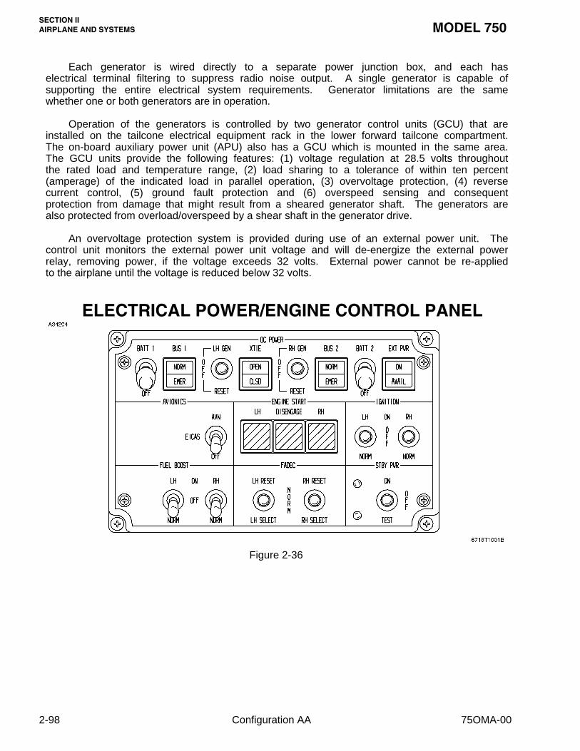
Each generator is wired directly to a separate power junction box, and each haselectrical terminal filtering to suppress radio noise output. A single generator is capable ofsupporting the entire electrical system requirements. Generator limitations are the samewhether one or both generators are in operation.
Operation of the generators is controlled by two generator control units (GCU) that areinstalled on the tailcone electrical equipment rack in the lower forward tailcone compartment.The on-board auxiliary power unit (APU) also has a GCU which is mounted in the same area.The GCU units provide the following features: (1) voltage regulation at 28.5 volts throughoutthe rated load and temperature range, (2) load sharing to a tolerance of within ten percent(amperage) of the indicated load in parallel operation, (3) overvoltage protection, (4) reversecurrent control, (5) ground fault protection and (6) overspeed sensing and consequentprotection from damage that might result from a sheared generator shaft. The generators arealso protected from overload/overspeed by a shear shaft in the generator drive.
An overvoltage protection system is provided during use of an external power unit. Thecontrol unit monitors the external power unit voltage and will de-energize the external powerrelay, removing power, if the voltage exceeds 32 volts. External power cannot be re-appliedto the airplane until the voltage is reduced below 32 volts.
ELECTRICAL POWER/ENGINE CONTROL PANEL
� � � � � � � � � � � � � � � � � � � � � � � � � � � � � � � � � � � � � � � � � � � � � � � � � � � � � � � � � � � � � � � � � � � � � � � � � � � � � � � � � � � � � � � � � � � � � � � � � � � � � � � � � � � � � � � � � � � � � � � � � � � � � �
� � � � � � � � � � � � � � � � � � � � � � � � � � � � � � � � � � � � � � � � � � � � � � � � � � � � � � � � � � � � � � � � � � � � � � � � � � � � � � � � � � � � � � � � � � � � � � � � � � � � � � � � � � � � � � � � � � � � � � � � � � � � � �
� � � � � � � � � � � � � � � � � � � � � � � � � � � � � � � � � � � � � � � � � � � � � � � � � � � � � � � � � � � � � � � � � � � � � � � � � � � � � � � � � � � � � � � � � � � � � � � � � � � � � � � � � � � � � � � � � � � � � � � � � � � � � �
� � � � � � � � � � � � � � � � � � � � � � � � � � � � � � � � � � � � � � � � � � � � � � � � � � � � � � � � � � � � � � � � � � � � � � � � � � � � � � � � � � � � � � � � � � � � � � � � � � � � � � � � � � � � � � � � � � � � � � � � � � � � � �
Figure 2-36
2-98 Configuration AA 75OMA-00

SECTION IIMODEL 750 AIRPLANE AND SYSTEMS
GENERATOR CONTROLS AND SWITCHES
A three position generator switch, located on the tilted panel (DC Power Panel),immediately to the left of the pedestal, is provided for each generator. The switch is labeledLH (RH) GEN, OFF and RESET. Selecting the GEN (ON) position with the engine running willextinguish the amber GEN OFF L-R EICAS annunciation and will supply a signal to thegenerator control unit which monitors the battery bus voltage. It will connect the generator tothe bus, unless voltage or amperage is such that the generator control unit (GCU) will notparallel the generator with other(s) which may be on the line, or voltage is otherwise out oftolerance. Placing the switch to the OFF position will disable the signal to the generatorcontrol unit, the generator will be dropped offline, and the amber GEN OFF L-R annunciationwill appear. The RESET position is a momentary position that will momentarily connect thearmature directly to the field creating a rapid buildup to 28.5 volts. The switch is springloaded from the RESET back to the OFF position; therefore, it must be manually positioned toGEN when the RESET feature is utilized, and the generator will then come back on line. TheRESET position will reset a generator that has been tripped as a result of an overvoltage,feeder fault, or if the fuel and hydraulic firewall shutoff valves have been activated. Generatoroperation will again be disabled during reset attempts if the fault still exists or until firewallshutoff valves have been de-activated. The MASTER WARNING indicator will flash at anytime both generators have faulted or have been tripped off the line for any reason, and a redEICAS message GEN OFF L-R will appear in the flashing mode. An attention tone will alsobe heard, and if the voice warning system is installed a voice synthesis will be heard until theannunciation is acknowledged.
DIRECT CURRENT (DC) POWER GENERATION AND DISTRIBUTION
DC power originating from the batteries, airplane generators, on board auxiliary powerunit or ground external power sources, is initially controlled with different main DC powerbusses being activated by current switching relays located in the aft power junction box. Thejunction box is constructed in three sections and is located at the forward end of the baggagecompartment on the aft side of a pressure bulkhead. A small isolated section of the mainelectrical power junction box contains components of the electrical emergency system. Threeseparate cables from each section of the junction box route DC power to the right and leftcircuit breaker panels in the cockpit. “Crossover” busses are used to permit convenientgrouping of related equipment. The entire system is protected by current limiters and circuitbreakers. Current limiters of 275 amperes capacity protect each connection between thecrossfeed bus, and the left and right main generator busses. An isolation relay separates theDC emergency bus from the crossfeed bus so that, if required, the emergency bus may beseparated from the other busses and their loads.
The left and right feed busses are connected through a crosstie (XTIE) relay. Thecrosstie relay is closed on the ground during initial power up and then opens automatically,when the second generator comes on line after engine start on the ground, to allow the leftand right electrical systems to operate independently. The crosstie relay can be pilotcontrolled using a XTIE/OPEN, CLSD switch annunciator in the electrical switch panel. In theevent that a generator overcurrent causes a generator to be automatically shut off, thecrosstie relay will be latched open and cannot be selected closed.
75OMA-00 Configuration AA 2-99

SECTION IIAIRPLANE AND SYSTEMS MODEL 750
Safety and Protective Features of the System Are:
f When any generator is connected to the distribution bus, application of external powerwill be prevented.
f Ground external power overvoltage protection is provided.
f Two separate and distinct distribution systems, and related subsystems, supply power.
f No malfunctioning power source can prevent the remaining power sources fromfurnishing power to essential loads.
f Individual, or collective disconnection of the electrical power sources, including batteries,is available in flight to the flight crew.
f When fuel and hydraulic firewall shutoffs are activated, the respective generators arede-activated, and cannot be re-activated until the fuel and firewall shutoffs are reopened.
f Generator overvoltage protection at 32.5, +0.5, -0.5 volts is provided.
f All circuit breakers are “trip free” and cannot be reset if a fault is present in the circuit.
f Each battery is provided with a separate switch to provide for individual batterydisconnection.
f Electric engine starting, which can result in high battery temperature, is used only on thesmall APU engine. The airplane engines are started pneumatically.
f Generators are monitored for impending primary bearing failures by the EICAS system.If the system senses that a bearing will fail within ten operating hours a cyan EICASmessage DC BEARING L-R-APU will be annunciated.
f The generators are equipped with secondary bearings which will maintain operation forup to twenty hours.
f Failure of bus tie fuse limiters will trigger an EICAS message.
2-100 Configuration AA 75OMA-00

SECTION IIMODEL 750 AIRPLANE AND SYSTEMS
� � � � � � � � � � � � � � � � � � � � � � � � � � � � � � � � � � � � � � � � � � � � � � � � � � � � � � � � � � � � � � � � � � � � � � � � � � � � � � � � � � � � � � � � � � � � � � � � � � � � � � � � � � � � � � � � � � � � � � � � � � � � � � �
� � � � � � � � � � � � � � � � � � � � � � � � � � � � � � � � � � � � � � � � � � � � � � � � � � � � � � � � � � � � � � � � � � � � � � � � � � � � � � � � � � � � � � � � � � � � � � � � � � � � � � � � � � � � � � � � � � � � � � � � � � � � � � �
� � � � � � � � � � � � � � � � � � � � � � � � � � � � � � � � � � � � � � � � � � � � � � � � � � � � � � � � � � � � � � � � � � � � � � � � � � � � � � � � � � � � � � � � � � � � � � � � � � � � � � � � � � � � � � � � � � � � � � � � � � � � � � �
� � � � � � � � � � � � � � � � � � � � � � � � � � � � � � � � � � � � � � � � � � � � � � � � � � � � � � � � � � � � � � � � � � � � � � � � � � � � � � � � � � � � � � � � � � � � � � � � � � � � � � � � � � � � � � � � � � � � � � � � � � � � � � �
Figure 2-37
� � � � � � � � � � � � � � � � � � � � � � � � � � � � � � � � � � � � � � � � � � � � � � � � � � � � � � � � � � � � � � � � � � � � � � � � � � � � � � � � � � � � � � � � � � � � � � � � � � � � � � � � � � � � � � � � � � � � � � � � � � � � � � �
� � � � � � � � � � � � � � � � � � � � � � � � � � � � � � � � � � � � � � � � � � � � � � � � � � � � � � � � � � � � � � � � � � � � � � � � � � � � � � � � � � � � � � � � � � � � � � � � � � � � � � � � � � � � � � � � � � � � � � � � � � � � � � �
� � � � � � � � � � � � � � � � � � � � � � � � � � � � � � � � � � � � � � � � � � � � � � � � � � � � � � � � � � � � � � � � � � � � � � � � � � � � � � � � � � � � � � � � � � � � � � � � � � � � � � � � � � � � � � � � � � � � � � � � � � � � � � �
� � � � � � � � � � � � � � � � � � � � � � � � � � � � � � � � � � � � � � � � � � � � � � � � � � � � � � � � � � � � � � � � � � � � � � � � � � � � � � � � � � � � � � � � � � � � � � � � � � � � � � � � � � � � � � � � � � � � � � � � � � � � � � �
� � � � � � � � � � � � � � � � � � � � � � � � � � � � � � � � � � � � � � � � � � � � � � � � � � � � � � � � � � � � � � � � � � � � � � � � � � � � � � � � � � � � � � � � � � � � � � � � � � � � � � � � � � � � � � � � � � � � � � � � � � � � � � �
� � � � � � � � � � � � � � � � � � � � � � � � � � � � � � � � � � � � � � � � � � � � � � � � � � � � � � � � � � � � � � � � � � � � � � � � � � � � � � � � � � � � � � � � � � � � � � � � � � � � � � � � � � � � � � � � � � � � � � � � � � � � � � �
ELECTRICAL COMPONENTS LOCATION
75OMA-00 Configuration AA 2-101/2-102


SECTION IIMODEL 750 AIRPLANE AND SYSTEMS
BATTERIESTwo 44 ampere-hour nickel-cadmium batteries are connected directly to their respective
left and right battery busses, which are connected, through isolation relays, to the emergencybattery bus.
Battery power is selected by the BATT 1 and BATT 2 switches. Battery 1 is located inthe left aft fuselage fairing and Battery 2 is located in the right aft fuselage fairing. They arevented overboard through tubes located on the belly beneath the batteries. Selecting BATT 1or BATT 2 supplies battery power to the respective LH and RH battery busses and alsoallows battery charging. The batteries are a secondary source of direct current (DC) powerthat is used to provide power during the engine starting sequence and to provide power to theemergency battery bus in the event of a dual generator failure. With no generator on line andthe BUS 1 and BUS 2 switches set to NORM, the batteries will provide power to all aircraftsystems, except interior master, for approximately 14 minutes. Selecting both bus switches toEMER within 5 minutes after loss of generator power will allow the battery busses to supplypower for approximately 60 minutes to the emergency bus equipment.
The main batteries are supplemented by a 2.5 ampere-hour, 28 VDC lead-acid powerpack, located in the airplane nose compartment, which provides emergency electrical powerto the standby instruments.
External power is applied to the external power bus when the ground power unit (GPU) isconnected to the airplane and the GPU is started. When the external power relay is closedby placing the EXT PWR switch to EXT PWR (ON) the external power is applied to thecrossfeed bus, and is available to the complete airplane electrical system. Ground externalpower will automatically be disconnected by the external power relay when a generator switchis placed to the GEN position after an engine has been started.
Both airplane batteries will charge from the ground power unit. With either battery switchin BATT and the ground power unit connected and in operation, external power will be appliedto the airplane busses and the respective battery will be charged. The ground power unitshould have the voltage adjusted to maintain 28.5 volts, +0.5 or -0.5 volts.
Nickel cadmium battery temperature should remain below 60°C (140°F). A thermalmonitoring system is installed as an integral part of each battery. The system providescontinual monitoring of the internal thermal condition of the batteries and will warn the pilot ifbattery overheat condition exists. If a temperature of 62.8°C or greater is sensed, it willilluminate a flashing red BATT 1-2 O'TEMP annunciation in the crew alerting system (CAS)area of the EICAS display unit. The master warning will also flash, and a double chime willsound. If the battery temperature continues to climb to 71°C, or if the second battery were toalso exceed 62.8°C, the system will re-activate and will annunciate again. Refer to theEmergency Procedures section of the FAA Approved Airplane Flight Manual, or to SectionThree of this manual for specific action to be taken when a battery overheat condition exists.Lead-acid batteries do not have temperature monitoring; therefore, these procedures do notapply.
If the ELEC bezel button on the EICAS display unit (DU) is pressed, the electrical systemcan be continuously monitored on the one section (page) of the DU that is selectable by thepilots. The battery temperature can be monitored digitally as well as the generator voltage,battery voltage, and DC amperage. A battery temperature of greater than 20°C to 62.7°C willbe digitally annunciated in green. A temperature of less than 20°C will be annunciated inamber. A temperature of 62.8°C will be annunciated in red; if the temperature rises above71°C the same message will be triggered again.
The batteries must be serviced per the maintenance manual when the batterytemperature exceeds 60°C (140°F).
75OMA-00 Configuration AA 2-103

SECTION IIAIRPLANE AND SYSTEMS MODEL 750
The OFF position of the BATT switches disconnects battery power from all the electricalbusses except the hot battery bus. Selection of BATT 1 or BATT 2 supplies power to theemergency bus, and through the emergency isolation relay, to the rest of the airplane busses.
When the battery switch is in the OFF position, certain electrical equipment will stilloperate, such as BATT 1 and BATT 2 sensing, certain forward and aft compartment lights,EICAS emergency power, and emergency exit lights, since power is taken directly from thehot battery bus.
INTERIOR MASTER SWITCH
A covered interior master switch, located just aft of the right circuit breaker panel, can beused to electrically isolate the cabin area, shutting off all power to it except emergency andexit lighting. Its primary purpose is to shut off power to the cabin in case of a cabin electricalfire, or of a generator failure. This amount of reduction will lower the electrical load to thepoint that a single generator will carry it, although a single generator will normally carry theregular electrical load of the airplane.
STANDBY POWER SWITCH
The STBY PWR switch controls power distribution from the standby battery, located inthe nose compartment, to the standby equipment bus. This switch must be selected to ONfor the standby equipment to operate. Electrical power will normally be supplied to thestandby equipment bus from the emergency bus if either airplane battery, generator orexternal power is on-line. After loss of battery, generator and/or external power, with theswitch ON, power will be drawn from the standby battery pack. This will be indicated by anamber light adjacent to the switch. In the OFF position, the standby equipment bus is notpowered, regardless of other airplane electrical configuration. The TEST position permits thecrew to test the lead-acid standby battery pack.
NOTE
Following loss of electrical power, the standby equipment battery pack willcontinue to supply electrical power to the following equipment for 60 minutes:standby altimeter/airspeed vibrator, standby attitude indicator, standby engineindicators and standby instrument lighting. If the airplane is on the ground,turning the standby power switch to OFF will turn off IRS power.
2-104 Configuration AA 75OMA-00

SECTION IIMODEL 750 AIRPLANE AND SYSTEMS
EMERGENCY LIGHTING BATTERIES
Two 1.5 ampere-hour, 18-cell, nickel-cadmium battery packs are installed in the airplane;one in the pilot's console and one in the left side of the raised aisle at the aft end of the cabin.The battery packs are connected to the airplane charging system and are being charged anytime the main airplane power is on. An emergency lighting switch (EMERG LTARM/ON/OFF), located at the left end of the pilot's tilt panel, is used to control the emergencylighting system and the emergency battery packs. The ON position directs power to theemergency lighting system from the main batteries/generators. The ARM position will providepower to the emergency lighting system from the emergency battery packs in the event theairplane should experience a 5G longitudinal deceleration, or if there is a loss of normalairplane power. The OFF position disables the emergency lighting system and theemergency battery packs. An amber warning light, located adjacent to the EMER LT switch,will illuminate when power is on the airplane, signifying the emergency lighting is off and thatthe EMER LT switch should be placed to the ARM position.
The battery packs provide the power for the cabin emergency lights, selected readinglights, cabin exit signs, and escape path lighting. One pack is dedicated to the cockpit andforward cabin while the second pack powers the mid and aft cabin emergency lighting. Thebatteries also provide power for the SEAT BELT and NO SMOKING illuminated signs.
75OMA-00 Configuration AA 2-105
SECTION IIAIRPLANE AND SYSTEMS MODEL 750
AUXILIARY POWER UNIT
An auxiliary power unit (APU) is mounted in the stinger of the airplane. The APU turbinepowers a DC generator which has a rated capacity of 200 amperes in flight and 300 ampereson the ground. It may be started and used up to an altitude of 31,000 feet. It may also beused to provide engine starting air, auxiliary bleed air for the air conditioning system and doorseal inflation, and therefore makes the airplane largely self sustaining on the ground.
Engine power for the APU is provided by a simple turbine using a single-stage centrifugalcompressor and a single-stage radial inflow turbine. Turbine maximum rated speed is 58,737RPM with a maximum continuous exhaust gas temperature of 665°C; a temperature of 718°Cconstitutes an overtemperature condition. Maximum start temperature is 973°C.
APU electrical power is controlled by a generator control unit (GCU) which is mounted inthe tailcone aft of the cabin pressure bulkhead, with the engine generator GCUs. Fuel for theAPU operation is provided from the left wing fuel hopper by the left fuel boost pump. The fuelboost pump is started, if not already running, any time the APU is put into operation. The APUis so designed that shaft loads (electricity generation) will have priority over an air bleed load.If the APU load is excessive, with air bleed and generator output being used, the amount ofair output will be reduced by the load control valve (LCV) in order to maintain the APU loadwithin its capacity.
The APU control panel is mounted in the cockpit, forward of the right circuit breakerpanel. APU RELAY ENGAGED and APU FAIL annunciator lights are mounted on the rightmeter panel. A logic control module, which provides an interface for the aircraft mountedcontrols and the APU digital engine sequencing unit (ESU), is located in the right main powerjunction box. The ESU is essentially a microprocessor that has been programmed to controland initiate a series of events necessary for satisfactory operation of the auxiliary power unit.Functions which are controlled by this logic are: auxiliary power unit start and sequence tooperation, malfunction indication and automatic shutdown during start, and malfunctionindication and shutdown during auxiliary power unit operation. The logic also sequences itselfto restart condition on re-application of power to the system after a shutdown.
The APU MASTER ON/OFF switch controls electrical power to the APU. TheTEST/PUSH switch causes the APU to repeat its internal tests. The APU/START/NORM/STOPswitch is spring loaded to NORM and is used to start or shut down the APU. The APUSTARTER DISENGAGE/NORMAL switch is spring loaded to NORMAL and is used todisengage the APU starter if it does not disengage normally. A READY TO LOAD annunciatorwill illuminate when the APU has started and is ready for the generator to be put on-line. TheBLEED AIR MAX COOL/ON/OFF switch controls the APU bleed air. The ON position is usedfor normal environmental bleed air extraction and for cooling. The maximum flow valvebypasses the bi-level flow control valves and, therefore, will not shut off environmental airduring engine start. The APU MAX COOL bleed air is not approved for engine start; the startpressure could be low, which would result in a hung start.
2-106 Configuration AA 75OMA-00

SECTION IIMODEL 750 AIRPLANE AND SYSTEMS
On starting, when the engine speed reaches approximately ten percent, the APUelectronic control box (ECB) completes a circuit to the fuel shutoff valve, ignition unit, andsurge control valve. The fuel shutoff valve is then energized open to permit fuel flow to thefuel nozzle assemblies, and the ignition fires the fuel-air charge in the combustion chamber.The surge control valve is energized open to permit reaction to compressor dischargepressure. When engine speed reaches 50 percent, the controller provides a signal for starterdisengagement. At approximately 60 percent RPM compressor discharge pressure opensthe surge control valve and dumps a small percentage of compressor discharge airoverboard, preventing engine surge. At 99 percent the controller opens the circuits to theignition unit, and acceleration continues to the no-load govern speed point. At governedengine speed the turbine discharge temperature is automatically regulated to withinestablished limits by the load control valve.
NOTE
Refer to the FAA Approved Airplane Flight Manual for Auxiliary Power UnitOperating Limitations and Procedures.
Fire protection is provided by a fire detector system and a fire extinguisher system. Anassociated warning light/switch (APU FIRE) located on the copilot's instrument panel willilluminate in case of an APU fire. An aural tone will also sound. The fire detector sensor isof the continuous loop gas filled type, which is routed around the APU at strategic points, andis connected to an alarm responder and to an integrity responder. A dedicated fire bottle isinstalled below the APU. The fire bottle is fired by lifting the cover on the illuminated APUFIRE switch/light and pressing the switch. The fire extinguishing system does not dischargeautomatically.
The APU is designed to handle full cabin loads prior to main engine starts. The APU isstarted electrically and can be started and operated up to a maximum altitude of 31,000 feet.It can be paralleled with the engine driven generators. Parallel operation is considered to bea variance of ten percent of the amount of the maximum rated amperage; therefore, a loadvariation of 40 amperes is acceptable. The APU ESU stores APU system fault data in anonvolatile memory and retains it from the last five APU cycles. If the APU is on-line oroperating in parallel with the engine generators, the automatic load shedding function of theelectrical system is inhibited. The APU directly feeds the crossfeed/emergency bus. At leastone battery switch must be on to operate the APU.
An APU shutdown switch is located inside the tailcone access door on the right aft sideof the door frame, to permit APU shutdown without requiring cockpit access.
AVIONICS POWER
Power to the avionics is controlled by an AVIONICS POWER ON/OFF switch located onthe AVIONICS POWER control panel, which is immediately to the right of the DC POWERcontrol panel. When in the ON position all avionics equipment receives power. AnEICAS/OFF switch, just to the right of the ON/OFF switch, supplies power only to the engineinstrument and crew alerting system (EICAS) bus (partial power). Only the left multifunctiondisplay (MFD) and EICAS system will then be powered. This switch allows the essentialEICAS equipment to be powered for maintenance, and for other functions which require onlyengine information or EICAS readings, thereby saving power-up cycles and operating time onthe complete EICAS system and the electronic flight instrument system (EFIS). The EICAS,EFIS, and other avionics systems of the Model 750 are direct current (DC), and thereforesystem inverters are not required.
75OMA-00 Configuration AA 2-107

SECTION IIAIRPLANE AND SYSTEMS MODEL 750
EXTERNAL POWER SWITCH
An external power switch (EXT PWR/OFF) is mounted on the DC power control panel. Itsfunction is to control the power from a ground power unit (GPU). In the EXT PWR position,external power is applied to the airplane busses, and overvoltage and undervoltage protectionis provided, but the batteries will not charge unless the battery switch(es) is/are turned on.
WINDSHIELD ALTERNATING CURRENT (AC) ELECTRICAL ANTI-ICESYSTEM
Windshield and forward cockpit side window anti-icing is provided by two 3.0 kilovolt-ampere alternators, one of which is mounted on the accessory drive case of each engine.They deliver three-phase alternating current (AC) power. The speed of the alternators is notgoverned, so their speed varies with engine speed, which causes the current cycle rate tovary. The cycle variations have no effect on the windshield heaters.
The windshields are divided into three heating sections: power from the left alternator isapplied to the left outboard and center sections of the left windshield, to the right windshieldinboard section, and to the right side window.
Power from the right alternator is applied to the right outboard and center sections of theright windshield, to the inboard section of the left windshield, and to the left side window.
Control switches for the system are located on the ANTI-ICE control panel which islocated to the right of the center pedestal on the tilt panel (WINDSHIELD ANTI-ICE LH/RH).The three position toggle switches are labeled OFF/HT ON/O'RIDE. Placing the switches toHT ON (center position) will initiate a ramp heating function which will gradually warm thewindshield to operating temperature. If anti-icing is needed immediately, such as whenunexpected icing is encountered, the switches may be placed immediately to O'RIDE positionand the ramp heating function will be bypassed. The switches are spring loaded out of theO'RIDE position and will automatically be positioned back to ON. The HT ON position shouldbe used for normal operation.
Three integral temperature sensors are incorporated in each windshield assembly. Onesensor is used as a primary sensor, one as a secondary or backup sensor, and the third is aspare. There is a control unit for each windshield side, mounted in the respective pilot orcopilot side console. The control units monitor the windshield temperature through theprimary sensor. If the primary sensor should develop a fault, the system will revertautomatically to the secondary sensor, and temperature monitoring will not be interrupted.The left and right main windshields are regulated to a temperature of 110°F.
The engine and crew alerting system (EICAS) constantly monitors the windshield heatand will alert the crew of a fault or overtemperature condition. An amber EICAS message,WSHLD O'TEMP L-R will illuminate, and electric power to the windshield will automatically becut off if windshield surface temperature exceeds 140°F. Power will be restored and anamber message will extinguish when the windshield surface temperature drops below 115°F.Another amber EICAS message, WSHLD HEAT INOP L-R, will illuminate if the electricalwindshield controller is unable to supply current to the heater elements. When any of theabove messages appear, a chime will sound.
The windshield anti-ice must be turned ON any time icing is detected. It may beoperated full time from engine start to shutdown and will improve cockpit comfort at highaltitude, particularly at night. Windshield anti-ice is also required for defogging the windshield.
2-108 Configuration AA 75OMA-00

SECTION IIMODEL 750 AIRPLANE AND SYSTEMS
CIRCUIT BREAKERS
Push-to-reset, pull-off type circuit breakers with the amperage rating marked on eachbreaker, are installed in panels located on both sides of the cockpit. The panels are readilyaccessible to the flight crew during flight. Panel configurations may vary from airplane toairplane due to differences in installed equipment; therefore, the panels shown are typicalinstallations.
Additional circuit breakers, to which flight crew access is not essential, are located in thetailcone junction boxes.
75OMA-00 Configuration AA 2-109

SECTION II MODEL 750 AIRPLANE AND SYSTEMS
2-110 Configuration AA 75OMA-00
CIRCUIT BREAKER PANEL
Figure 2-39 (Sheet 1 of 2)

MODEL 750 SECTION II AIRPLANE AND SYSTEMS
75OMA-00 Configuration AA 2-111
CIRCUIT BREAKER PANEL
Figure 2-39 (Sheet 2)