Embed Size (px)
Citation preview

Electrical MethodologyA methodology to size the electrical equipment and the powercables of a photovoltaic plantMarch 2, 2021
Ignacio Álvarez Iberlucea,Álvaro Pajares Barroso,Hassan Farhat,Félix Ignacio Pérez Cicala,Miguel Ángel Torrero Rionegro

Abstract
Abstract
This electrical methodology explains the electrical calculations that the software does throughoutthe PV plant. It also explains the di�erent criteria of each of the electrical cabling standards thatpvDesign o�ers. The following topics are introduced in the methodology:
• The calculation of the maximum and minimum number of modules per string.• The types of PV plant electrical con�gurations that pvDesign o�ers.• The sizing of the equipment’s protective devices such as fuses and breakers.• The model that has been followed to size cables according to IEC and NEC standards.
Electrical Methodology 1

Contents
Contents
Abstract 1
1 Electrical equipment calculation 61.1 Number of modules per string calculation . . . . . . . . . . . . . . . . . . . . . . 6
1.1.1 Consequences of considering minimum historical temperature as cell tem-perature . . . . . . . . . . . . . . . . . . . . . . . . . . . . . . . . . . . . 8
1.2 Electrical con�guration . . . . . . . . . . . . . . . . . . . . . . . . . . . . . . . . 101.3 Protective devices . . . . . . . . . . . . . . . . . . . . . . . . . . . . . . . . . . . 11
1.3.1 Fuses . . . . . . . . . . . . . . . . . . . . . . . . . . . . . . . . . . . . . . 111.3.2 Breakers . . . . . . . . . . . . . . . . . . . . . . . . . . . . . . . . . . . . 11
2 Electrical Sizing Criteria 122.1 Introduction . . . . . . . . . . . . . . . . . . . . . . . . . . . . . . . . . . . . . . 122.2 Cable selection based on the maximum current-carrying capacity . . . . . . . . 13
2.2.1 IEC standard . . . . . . . . . . . . . . . . . . . . . . . . . . . . . . . . . 142.2.2 NEC standard . . . . . . . . . . . . . . . . . . . . . . . . . . . . . . . . . 152.2.3 Australian standard . . . . . . . . . . . . . . . . . . . . . . . . . . . . . . 162.2.4 National Standard of the People’s Republic of China . . . . . . . . . . . 162.2.5 Temperature of the cable . . . . . . . . . . . . . . . . . . . . . . . . . . . 17
2.3 Cable selection based on short-circuit temperature rise . . . . . . . . . . . . . . 172.3.1 IEC standard . . . . . . . . . . . . . . . . . . . . . . . . . . . . . . . . . 192.3.2 NEC standard . . . . . . . . . . . . . . . . . . . . . . . . . . . . . . . . . 192.3.3 Australian standard . . . . . . . . . . . . . . . . . . . . . . . . . . . . . . 202.3.4 National Standard of the People’s Republic of China . . . . . . . . . . . 212.3.5 Consequences of taking the cable heat dissipation factor = 1 . . . . . . . 21
2.4 Cable selection based on voltage drop . . . . . . . . . . . . . . . . . . . . . . . . 232.4.1 Consequences of taking the maximum operational temperature of the
insulation for cable sizing based on voltage drop . . . . . . . . . . . . . 242.4.2 Consequences of taking the AC resistance equals to the DC resistance . 252.4.3 Consequences of not considering the reactive power . . . . . . . . . . . 26
Bibliography 29
A Determining cable cross-sections 31A.1 Medium voltage cables . . . . . . . . . . . . . . . . . . . . . . . . . . . . . . . . 31
A.1.1 IEC standard . . . . . . . . . . . . . . . . . . . . . . . . . . . . . . . . . 31A.1.2 NEC standard . . . . . . . . . . . . . . . . . . . . . . . . . . . . . . . . . 33
A.2 Low voltage cables. String level . . . . . . . . . . . . . . . . . . . . . . . . . . . 34A.2.1 IEC standard . . . . . . . . . . . . . . . . . . . . . . . . . . . . . . . . . 34
Electrical Methodology 2

Contents
A.2.2 NEC standard . . . . . . . . . . . . . . . . . . . . . . . . . . . . . . . . . 36
B Determining electrical characteristics of the cable 38B.1 Determining the electrical characteristics of a medium voltage cable . . . . . . . 38
B.1.1 Temperature of the cable . . . . . . . . . . . . . . . . . . . . . . . . . . . 38B.1.2 Voltage drop . . . . . . . . . . . . . . . . . . . . . . . . . . . . . . . . . . 38B.1.3 Withstand short-circuit current . . . . . . . . . . . . . . . . . . . . . . . 39
Electrical Methodology 3

List of Figures
List of Figures
1.1 Maximum number of modules per string with module temperature from -10 ºCto -8 ºC. Source: Own elaboration. . . . . . . . . . . . . . . . . . . . . . . . . . . 9
1.2 Maximum number of modules per string with module temperature from 5 ºC to7 ºC. Source: Own elaboration. . . . . . . . . . . . . . . . . . . . . . . . . . . . . 9
1.3 Maximum number of modules per string with module temperature from 10 ºC to12 ºC. Source: Own elaboration. . . . . . . . . . . . . . . . . . . . . . . . . . . . 9
1.4 Maximum number of modules per string with module temperature from 20 ºC to22 ºC. Source: Own elaboration. . . . . . . . . . . . . . . . . . . . . . . . . . . . 10
2.1 Dissipation factor and Cu XLPE cross-section based on short-circuit temperaturerise [<<2]. Source: Own elaboration. . . . . . . . . . . . . . . . . . . . . . . . . 22
2.2 Dissipation factor and Al XLPE cross-section based on short-circuit temperaturerise [<<2]. Source: Own elaboration. . . . . . . . . . . . . . . . . . . . . . . . . 23
2.3 Al XLPE cable cross-section based on resistivities at di�erent temperatures [<<2].Source: Own elaboration. . . . . . . . . . . . . . . . . . . . . . . . . . . . . . . . 25
2.4 AC and DC resistivities for a Cu cable based on IEC. Source: Own elaboration. . 262.5 AC and DC resistivities for a Cu cable based on Tables 8 and 9 of the NEC stan-
dard. Source: Own elaboration. . . . . . . . . . . . . . . . . . . . . . . . . . . . . 262.6 Average increase of cross-sections for Al cables considering di�erent voltage
drops for cos phi = 0.95, 0.9 and 0.85, and di�erent cable lengths. Source: Ownelaboration . . . . . . . . . . . . . . . . . . . . . . . . . . . . . . . . . . . . . . . 27
2.7 Average increase of cross-sections for Cu cables considering di�erent voltagedrops for cos phi = 0.95, 0.9 and 0.85, and di�erent cable lengths. Source: Ownelaboration . . . . . . . . . . . . . . . . . . . . . . . . . . . . . . . . . . . . . . . 28
Electrical Methodology 4

List of Tables
List of Tables
2.1 Correction factors applied according to IEC standards, [4] and [5]. . . . . . . . . 142.2 Correction factors applied according to NEC standard [2] . . . . . . . . . . . . . 162.3 Correction factors applied according to Australian standards, [6] and [7]. . . . . 162.4 Correction factors applied according to GB 50217-2018 [8] . . . . . . . . . . . . 172.5 Constants that depend on the nature of the conductor . . . . . . . . . . . . . . . 192.6 Maximum conductor temperatures for di�erent types of insulating compound
according to IEC [4] and [5]. . . . . . . . . . . . . . . . . . . . . . . . . . . . . . 192.7 Maximum conductor temperatures for di�erent types of insulating compound
according to NEC [2]. . . . . . . . . . . . . . . . . . . . . . . . . . . . . . . . . . 202.8 Maximum conductor temperatures for di�erent types of insulating compound
according to Australian standards [6]. . . . . . . . . . . . . . . . . . . . . . . . . 202.9 Di�erences between the : used in pvDesign and the one given by the Australian
standard [6]. . . . . . . . . . . . . . . . . . . . . . . . . . . . . . . . . . . . . . . 202.10 Maximum conductor temperatures for di�erent types of insulating compound
according to [8]. . . . . . . . . . . . . . . . . . . . . . . . . . . . . . . . . . . . . 212.11 Di�erences between the : used in pvDesign and the one given by the Chinese
standard [8]. . . . . . . . . . . . . . . . . . . . . . . . . . . . . . . . . . . . . . . 212.12 Maximum conductor temperatures for di�erent types of insulating in normal
condition to electrical standards . . . . . . . . . . . . . . . . . . . . . . . . . . . 24
A.1 Correction factors according to IEC standard for MV cables. . . . . . . . . . . . 32A.2 Correction factors according to NEC standard for MV cables. . . . . . . . . . . . 34A.3 Correction factors according to IEC standard for LV cables. . . . . . . . . . . . . 35A.4 Correction factors according to NEC standard for LV cables. . . . . . . . . . . . 36
Electrical Methodology 5

Chapter 1. Electrical equipment calculation
Chapter 1
Electrical equipment calculation
1.1 Number of modules per string calculationThe number of modules that can be connected in series in a PV plant is constrained by twoconditions. The �rst condition is that the voltage of the modules must always be lower than themaximum input voltage of the inverter and the maximum module voltage. The second conditionis that the voltage of the modules must be within the voltage range that maximizes the e�ciencyof the inverter.
The upper limit of the number of modules per string is constrained by both conditions, and thesecond condition marks the lower limit.
The maximum voltage will be reached in low-temperature conditions when the modules operatein open-circuit. Therefore, based on the minimum operating temperature, the expression used tocalculate the maximum number of modules in series according to the �rst condition mentionedabove is given by Equation 1.1.
#Bmax(+max DC system) =+max DC system
+oc()cell min)(1.1)
It is necessary to calculate the open-circuit voltage of the PV cells as a function of their temper-ature using Equation 1.2.
+oc()cell min) = +oc(25◦�) + ()cell min − 25) ·+oc(25◦�) ·`
100(1.2)
And the cell temperature is obtained from the minimum air temperature at the location, as rec-ommended in IEC 62548 [1] and NEC 2017 [2] standards, which is calculated using Equation 1.3.
)cell min = )air min (1.3)
Where:
Electrical Methodology 6

Chapter 1. Electrical equipment calculation
• #Bmax)(+max DC system) is the maximum number of modules per string that can be de�nedwithout exceeding the maximum DC voltage.
• +max DC system is the minimum of the following values: maximum input voltage at the in-verter and maximum approved voltage of the module in [V].
• +oc()cell min) is the open-circuit voltage of the cell at its minimum temperature in [V].• +oc(25◦�) is the open-circuit voltage of the cell at standard conditions in [V].• ` is the module temperature coe�cient of Voc in [%/ºC].• )cell min is the minimum temperature of the solar cells in [ºC].• )air min is the minimum historical value of air temperature at the location in [ºC].
To determine the maximum number of modules per string, the second condition must be alsotaken into consideration. The expression used to calculate the maximum number of modules perstring that satis�es this condition is given by Equation 1.4.
#Bmax(+max MPPT inverter) =+max MPPT inverter
+mp(25◦�)(1.4)
Where:
• #Bmax(+max MPPT inverter) is the maximum number of modules per string that can be de�nedto work within the voltage range that maximizes inverter’s e�ciency.
• +max MPPT inverter is the maximum voltage of the MPPT voltage range of the inverter in [V].• +mp(25◦�) is the voltage at the maximum power of the cell at standard conditions in [V].
Once both conditions have been evaluated, the most restrictive value of maximum number ofmodules per string is considered as the �nal one.
The second condition, which will de�ne the minimum number of modules in series, is a functionof the maximum temperature of the module cell. This temperature will be reached when themodules generate a higher voltage, in low ambient temperature conditions. Therefore, based onthe maximum operating temperature, the expression used to calculate the minimum number ofmodules is given by Equation 1.5.
#Bmin =+min MPPT inverter
+mp()cell max)(1.5)
The voltage at the maximum power of the photovoltaic cells and cell temperature are calculatedusing Equation 1.6.
+mp()cell max) = +mp(25◦�) + ()cell max − 25) ·+mp(25◦�) ·`
100(1.6)
And, the cell temperature is obtained from Equation 1.7.
)cell max = )air max + �max ·)#$�) (◦�)−20◦�
800, /<2 (1.7)
Electrical Methodology 7

Chapter 1. Electrical equipment calculation
Where:
• #Bmin is the minimum number of modules per string.• +min MPPT inverter is the minimum voltage of the MPPT voltage range of the inverter in [V].• +mp()cell max) is the voltage at the maximum power of the module at the maximum cell
temperature in [V].• +mp(25◦�) is the open-circuit voltage of the cell at standard conditions in [V].• ` is the module temperature coe�cient of Voc in [%/ºC].• )cell max is the maximum temperature of the solar cells in [ºC].• )air max is the maximum historical value of air temperature at the location in [ºC].• )#$�) (◦�)−20◦� is the nominal operating cell temperature (45 °C), measured at 800 W/<2
irradiance, with spectral distribution AM 1.5 G, air temperature 20 °C and wind speed 1m/s.
• �max is the maximum irradiance in [W/<2]. It equals 1000 [W/<2].
1.1.1 Consequences of consideringminimumhistorical temperature ascell temperature
When the �rst condition is approached, deviations from the method above mentioned can beapplied with engineering justi�cation. A method that is commonly applied in ground-mountedPV plant designs is the one de�ned by IEC TS 62738 [3], which recommends to take as celltemperature the minimum historical temperature limited to sunlight hours when irradiance is10 W/<2 or less.
The minimum historical temperature normally occurs after the sunrise, when the atmosphere hasbeen longer without the sun heating it up. For this reason, di�erences between both temperatures(minimum historical temperature and minimum historical temperature limited to sunlight hours)do not normally cause di�erences in the maximum number of modules per string.
Considering a system where the DC maximum voltage is 1500 V,+oc of the module is 49.6 V andthe module temperature coe�cient is -0.233 %/ºC and minimum historical temperatures of -10ºC, 0 ºC, 10ºC and 20 ºC, Figure 1.1, Figure 1.2, Figure 1.3 and Figure 1.4 represent the temperaturevariation needed in the module to increase the recommended value of modules per string.
Electrical Methodology 8

Chapter 1. Electrical equipment calculation
Figure 1.1: Maximum number of modules per string with module temperature from -10 ºC to -8ºC. Source: Own elaboration.
Figure 1.2: Maximum number of modules per string with module temperature from 5 ºC to 7 ºC.Source: Own elaboration.
Figure 1.3: Maximum number of modules per string with module temperature from 10 ºC to 12ºC. Source: Own elaboration.
Electrical Methodology 9

Chapter 1. Electrical equipment calculation
Figure 1.4: Maximum number of modules per string with module temperature from 20 ºC to 22ºC. Source: Own elaboration.
These �gures show that the di�erences between minimum historical temperature and the min-imum historical temperature limited to sunlight hours must be 0.6 ºC, 1.7 ºC, 11. 6 ºC and 1.6ºC for the cases where the minimum historical temperature is -10 ºC, 5 ºC, 10 ºC and 20 ºC, re-spectively, to denote an increase in the maximum recommended number of modules per string.Moreover, in a range of 30 ºC (from -10 ºC to 20 ºC), 2 units in the number of modules per stringwere increased (from 27 to 29).
Due to the small di�erences in the results obtained with both methods and to be in compliancewith NEC 2017[2], pvDesign will use as cell temperature the minimum historical temperature tocalculate the maximum number of modules per string.
1.2 Electrical configurationpvDesign o�ers four types of electrical con�gurations in the case of central inverters and two inthe case of string inverters.
In the case of central inverters, the con�gurations are as follows:
• String Box: The strings of modules are connected to a string box. Then groups of stringboxes are connected to central inverters. The number of strings per string box ranges from4 to 36.
• Bus System: The strings are connected to a DC Bus collector and the connections reachthe inverters. The number of strings per DC Bus collector ranges from 4 to 36.
• String Box L2 (Field): The strings are connected to string boxes which are connected toanother level of string boxes which we call L2 that are located in the �eld. Finally, groupsof these are boxes are connected to the central inverters. The number of strings per level1 string box varies from 4 to 16. And the number of level 1 string boxes per level 2 stringbox ranges between 12 and 16.
• String Box L2 (Station): The strings are connected to string boxes which are connected toanother level of string boxes which we call L2 that are located in the power stations. Andgroups of these are �nally connected to the central inverters.
Electrical Methodology 10

Chapter 1. Electrical equipment calculation
In the case of string inverters, the two possible con�gurations are:
• String Inverter (Field): The strings are connected directly to the string inverters. The stringinverters are located in the �eld (outside the power stations).
• String Inverter (Station): The string inverters, in this case, are located in the power stations.
1.3 Protective devices1.3.1 FusesThe fuses of the LV DC side must meet the following conditions:
1. The fuse current must be greater than or equal to 1.56 times the module’s short circuitcurrent.
�fuse ≥ 1.56 · �sc (1.8)
2. The fuse current must have a value between the cable’s load current and its maximumcurrent capacity.
�load ≤ �fuse ≤ �ccc (1.9)
Where:
• �fuse is the rated current of the fuse in [A].• �sc is the short-circuit current of the PV module for string cables and the short-circuit
current of the PV module multiplied by the number of strings per box/DC bus collector forupper PV plant levels in [A].
• �load is the load current through the cable in [A].• �ccc is the maximum current capacity of the cable in [A].
1.3.2 BreakersTo size the on-load circuit breaker, the following conditions must be considered:
1. The switch current rating must be greater than or equal to 1.25 times the module’s shortcircuit current.
�breaker ≥ 1.25 · �sc (1.10)
2. The switch current rating must be less than or equal to the maximum current capacity ofcables.
�breaker ≤ �ccc (1.11)
Where:
• �breaker is the rated current of the breaker in [A].• �sc is the short-circuit current of the PV module for string cables and the short-circuit
current of the PV module multiplied by the number of strings per box/DC bus collector forupper PV plant levels in [A].
• �ccc is the maximum current capacity of the cable in [A].
Electrical Methodology 11
Chapter 2. Electrical Sizing Criteria
Chapter 2
Electrical Sizing Criteria
This section explains the di�erent criteria followed by each of the electrical standards that pvDe-sign o�ers.
2.1 IntroductionTo size the cables of the PV plant based on the electrical standards, the following criteria mustbe satis�ed:
• Current-carrying capacity criterion: The operating current is corrected based on the dif-ferent characteristics of the installation and the site. This corrected value must then belower than the maximum current-carrying capacity that the cable can withstand. Thesemaximum current-carrying capacity values are based on standard tables.
• Short-circuit temperature rise criterion: The short-circuit current must be lower than thelimit supported by the cabling. This criterion is taking into account only for medium volt-age cables.
• Voltage drop criterion: The criterion states that the voltage drop in each cable should belower than the maximum values established by the user in pvDesign. AAlthough thiscriterion is considered to size the cable, not complying with it doesn’t imply the damageof the cable; however, it implies that the losses will be greater.
The constraints considered when calculating the low voltage (LV) and medium voltage (MV)cables are:
• To minimize the costs using the minimum valid cable cross-section(s). We tend to limitthe number of cross-sections to a maximum of two in each sub-system of the PV plant(standardize the cable cross-sections).
• Copper is proposed as the conducting material for the LV DC string cables. Aluminium isproposed as the conducting material for the rest of cables (DC, AC and MV).
The assumptions made when sizing and rating the cables are the following:
• The soil temperature equals 25°C, if no information is available.
Electrical Methodology 12

Chapter 2. Electrical Sizing Criteria
• The ambient temperature is the maximum historical temperature of the site (provided bythe meteo data source).
• The soil resistivity is equal to 1 K·m/W, if no information is available.• The depth of cables are 700 mm for buried LV cables and 900 mm for MV cables.• There is no space between LV cables, and the MV cables are spaced 0.2 m between group
centres.• String cables are fastened to the structures. The rest of LV cables are directly buried in
trenches. MV radial networks from the power stations to the substation are directly buriedin trenches.
2.2 Cable selectionbasedon themaximumcurrent-carryingcapacity
The current-carrying capacity is de�ned as the maximum current that can �ow through an elec-tric conductor without damaging it. This value varies depending on the conductor, environ-mental conditions, cross-section, insulating material, the number of grouped conductors, amongothers.
The operating current is corrected based on the di�erent characteristics of the installation andthe site. This corrected value must then be lower than the maximum current-carrying capacitythat the cable can withstand.
The equation for the corrected allowed current is given by Equation 2.1.
�sizing ≤ �ccc (2.1)
Where:
• �sizing is the sizing current for the current-carrying capacity criterion in [A].• �ccc are the current values standardized for each cable cross-section based on the cable and
the installation characteristics in [A]
As it is presented in the following sections, the operating current of the cable is corrected withsome factors:
1. An ambient air temperature correction factor is only applied when the cables are exposedto air or installed in trays fastened to the structures.
2. A soil temperature correction factor is only applied when the cables are directly buried intrenches or underground cable ducts.
3. A soil resistivity correction factor is only applied when the cables are directly buried intrenches or underground cable ducts.
4. A depth of burial correction factor is only applied when the cables are directly buried intrenches or underground cable ducts.
5. Grouping cables together leads to additional heating of the cables which increases thecurrent passing through them.
Electrical Methodology 13

Chapter 2. Electrical Sizing Criteria
2.2.1 IEC standardBased on IEC standards [4] and [5], the sizing current is given by Equation 2.2.
�sizing =�operating
��(2.2)
Where:
• �sizing is the sizing current for the current-carrying capacity criterion in [A].• �operating is the load current running through the cable in [A].• �� is the product of all the applied correction factors.
The ambient and soil temperature correction factors are calculated using Equation 2.3.
��temp =
[\ i − \a
\ ′i − \ ′a·V + \ ′iV + \ i
] 12
(2.3)
Where:
• ��temp is the ambient or soil temperature correction factor.• V is the reciprocal of the temperature coe�cient of resistivity at 0ºC. This parameter equals
234.5 ºC for copper (Cu) and 228 ºC for aluminium (Al).• \ ′i is the conductor rated temperature at which the base ampacity is speci�ed in [ºC].• \ i is the maximum allowable conductor temperature in [ºC]. It equals the maximum oper-
ational insulator temperature in normal operation.• \ ′a is the ambient or soil temperature at which the base ampacity is speci�ed in [ºC].• \a is the actual soil or ambient temperature in [ºC]. It equals the maximum historical air
temperature of the site or a temperature of 25 ºC underground cables.
The other correction factors that are used to size a cable according to IEC standards are given inTable 2.1.
Table 2.1: Correction factors applied according to IEC standards, [4] and [5].
Correction Factors For MV cables:IEC 60502-2
For LV cables:IEC 60364-5-52
For soil thermal resistivities Table B.14, B.15, B.16, and B.17 Table B.52.16For depths of laying Table B.12 and B.13 Not applied
For groups of cables Table B.18, B.19, B.20,B.21, B.22, and B.23 Table B.52.17, B.52.18, B.52.19
According to IEC standards [4] and [5], in order to compute the correction factor for a group ofcables, there are some considerations depending on the current running through the cable:
• For DC cables: Two single-core cables or one multi-core cable are considered as one current-carrying conductor.
Electrical Methodology 14

Chapter 2. Electrical Sizing Criteria
• For AC cables: Three single-core cables or one multi-core cable are considered as onecurrent-carrying conductor.
2.2.2 NEC standardBased on the Article 690 of the NEC standard [2], the sizing current for the output circuit of aPV plant (from inverters to the substation) is given by Equation 2.4.
�sizing =�operating
��(2.4)
Where:
• �sizing is the sizing current for the current-carrying capacity criterion in [A].• �operating is the load current running through the cable in [A]. It is the inverter continuous
output current for string inverters and the operating current for the MV system.• �� is the product of all the applied correction factors.
The sizing current for the photovoltaic source circuit (from modules to the inverters) is given byEquation 2.5.
�sizing =<0G (�corrected , �OCPD) (2.5)
Where �corrected is calculated using Equation 2.6.
�corrected =1.25 · �sc
��(2.6)
Where:
• �corrected is the current corrected by factors in [A].• �sc is the short-circuit current of the PV module for the string cables and the short-circuit
current of the module multiplied by the number of strings per box/DC bus in [A].• �� is the product of all the applied correction factors.
And the �OCPD is calculated by Equation 2.7.
1.25 · (1.25 · �sc) = 1.56 · �sc ⇒ �OCPD (2.7)
After that, we raise the result to the next standard fuse or circuit breaker size de�ned in section240.6 of the NEC. The obtained current will be denoted as �OCPD.
Where:
• �OCPD is the protective device rated current de�ned in section 240.6 of the NEC in [A].• �sc is the short-circuit current of the PV module for the string cables and the short-circuit
current of the module multiplied by the number of strings per box/DC bus in [A].
Electrical Methodology 15

Chapter 2. Electrical Sizing Criteria
The ambient and soil temperature correction factors are calculated using Equation 2.3. The othercorrection factors that are used to size a cable according to NEC standards are given in Table 2.2.
Table 2.2: Correction factors applied according to NEC standard [2]
Correction Factors For MV and LV cables:NEC 2017
For soil thermal resistivities IEEE Std 399-1997Table 13-5, 13-6, 13-7
For depths of laying NEC Annex B, Section B.3(b)For groups of cables NEC Annex B, Table B.310.15(B)(2)(11)
According to NEC standards, in order to compute the correction factor for a group of cables,there are some considerations depending on the current running through the cable:
• For DC cables: Two single-core cables or one multi-core cable are considered as twocurrent-carrying conductors.
• For AC cables: Three single-core cables or one multi-core cable are considered as threecurrent-carrying conductors.
2.2.3 Australian standardBased on [6] and [7], the sizing current is given by Equation 2.2, where the ambient and soilresistivity correction factors are calculated using Equation 2.3. and the other correction factorsare given by the tables mentioned in Table 2.3.
Table 2.3: Correction factors applied according to Australian standards, [6] and [7].
Correction Factors For MV cables:Prysmian Guide
For LV cables:AS 3008.1.1
For soil thermal resistivities Ratings information (page 135-136) Table 29For depths of laying Ratings information (page 135-137) Table 28
For groups of cables Ratings information(page 136-137)
Table 22, Table 25and Table 26
The Australian standard considers one circuit to compute the correction factor for a group ofcables as any multicore cable with 2 or 3 current-carrying cores or a group of single core cableswith 2 or 3 current-carrying cables.
2.2.4 National Standard of the People’s Republic of ChinaThis standard has been implemented according to [8], being the sizing current calculated byusing Equation 2.2. The ambient and soil temperature correction factors have been calculated byusing Equation 2.3, and the other correction factors considered are de�ned in Table 2.4.
Electrical Methodology 16
Chapter 2. Electrical Sizing Criteria
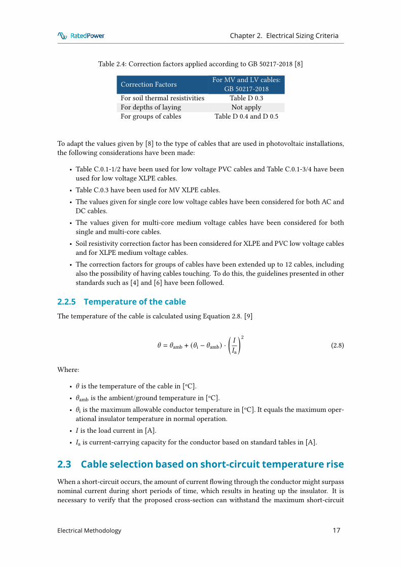
Table 2.4: Correction factors applied according to GB 50217-2018 [8]
Correction Factors For MV and LV cables:GB 50217-2018
For soil thermal resistivities Table D 0.3For depths of laying Not applyFor groups of cables Table D 0.4 and D 0.5
To adapt the values given by [8] to the type of cables that are used in photovoltaic installations,the following considerations have been made:
• Table C.0.1-1/2 have been used for low voltage PVC cables and Table C.0.1-3/4 have beenused for low voltage XLPE cables.
• Table C.0.3 have been used for MV XLPE cables.• The values given for single core low voltage cables have been considered for both AC and
DC cables.• The values given for multi-core medium voltage cables have been considered for both
single and multi-core cables.• Soil resistivity correction factor has been considered for XLPE and PVC low voltage cables
and for XLPE medium voltage cables.• The correction factors for groups of cables have been extended up to 12 cables, including
also the possibility of having cables touching. To do this, the guidelines presented in otherstandards such as [4] and [6] have been followed.
2.2.5 Temperature of the cableThe temperature of the cable is calculated using Equation 2.8. [9]
\ = \amb + (\ i − \amb) ·(�
�a
)2(2.8)
Where:
• \ is the temperature of the cable in [ºC].• \amb is the ambient/ground temperature in [ºC].• \ i is the maximum allowable conductor temperature in [ºC]. It equals the maximum oper-
ational insulator temperature in normal operation.• � is the load current in [A].• �a is current-carrying capacity for the conductor based on standard tables in [A].
2.3 Cable selection based on short-circuit temperature riseWhen a short-circuit occurs, the amount of current �owing through the conductor might surpassnominal current during short periods of time, which results in heating up the insulator. It isnecessary to verify that the proposed cross-section can withstand the maximum short-circuit
Electrical Methodology 17

Chapter 2. Electrical Sizing Criteria
current. This criterion is only applied in the case of MV cables and the equation that is appliedis valid for all the electrical standards. [10]
The cross-section of the cable is given by Equation 2.9.
( =�AD ·
√C
:=�sc ·√C
Y · : (2.9)
Where:
• ( the cable cross-section in [<<2].• �AD is the short-circuit current for adiabatic conditions.• �sc is the short-circuit current. The complete calculation of this short-circuit current is
presented in [11].• Y is the cable heat dissipation factor. For adiabatic conditions Y = 1.• C is the short-circuit duration in [s]. It is equal to 1 [s].• : is given by Equation 2.10.
: = ·
√;=
(\f + V\ i + V
)(2.10)
Where:
• is a constant that depends on the nature of the conductor and the temperature limitof the insulator in [�B0.5/<2]. This parameter equals 226�B0.5/<<2 for copper (Cu) and148�B0.5/<<2 for aluminium (Al).
• V is the reciprocal of the temperature coe�cient of resistivity at 0ºC. This parameter equals234.5 ºC for copper (Cu) and 228 ºC for aluminium (Al).
• \f is the �nal short circuit temperature of the conductor in [ºC]. Its value depends on thestandard.
• \ i is the maximum allowable conductor temperature in [ºC]. It is equal to the maximumoperational insulator temperature in normal operation.
Hence, the cross-section of the cable is given by Equation 2.11.
( =�sc ·√C
·
√;=
(\f + V\ i + V
) (2.11)
Where the that is a constant that depends on the nature of the conductor and the temperaturelimit of the insulator and V is the reciprocal of the temperature coe�cient of resistivity at 0ºC,are shown in Table 2.5.
Electrical Methodology 18

Chapter 2. Electrical Sizing Criteria
Table 2.5: Constants that depend on the nature of the conductor
Conductor material K [�B0.5/<2] V [ºC]Copper 226 234.5Aluminium 148 228
2.3.1 IEC standardThe IEC standards that have been followed to perform this calculation are [4] and [5]. The IEC60502-2 presents the maximum conductor temperatures for di�erent types of insulating com-pound and they can be seen in Table 2.6.
Table 2.6: Maximum conductor temperatures for di�erent types of insulating compound accord-ing to IEC [4] and [5].
Maximum conductor temperature [ºC] XLPE EPRin normal operation, \ i 90 90in short-circuit conditions, \f 250 250
2.3.2 NEC standardAccording to Table 240.92(B) in [2], conductors are considered to be protected under short-circuitconditions when their short-circuit temperature limit is not exceeded. Conductors heating undershort-circuit conditions is determined by Equation 2.12 or Equation 2.13.
� 2sc · C = 0.0297 · (2Cu · ;>610(\f + 234.5\ i + 234.5
)(2.12)
� 2sc · C = 0.0125 · (2Al · ;>610(\f + 228\ i + 228
)(2.13)
Where:
• ( the cable cross-section in [cmils].• �sc the maximum short-circuit current in [A].• \f is the �nal short circuit temperature of the conductor in [ºC]. Its value depends on the
standard.• \ i is the initial short circuit temperature of the conductor in [ºC]. Its value depends on the
standard.• C is the short-circuit duration in [s]. It is equal to 1 seconds.
However, by applying Equation 2.14 and Equation 2.15, the NEC equations to calculate the sectionbased on the short-circuit rise criterion are the same as the method followed by the IEC.
;>610(G) =;=(G)2.3
(2.14)
1<<2 = 1973.5 2<8; (2.15)
Electrical Methodology 19

Chapter 2. Electrical Sizing Criteria
(Cu =�sc ·√C√
0.02972.3
· 1973.5 ·
√;=
(\f + 234\ i + 234
) ⇒ Cu = 224.1 ≈ 226�B0.5/<<2 (2.16)
(Al =�sc ·√C√
0.01252.3
· 1973.5 ·
√;=
(\f + 228\ i + 228
) ⇒ Al = 145.4 ≈ 148�B0.5/<<2 (2.17)
The NEC presents the maximum conductor temperatures for di�erent types of insulating com-pound and they can be seen in Table 2.7.
Table 2.7: Maximum conductor temperatures for di�erent types of insulating compound accord-ing to NEC [2].
Maximum conductor temperature [ºC] THHN XHHNin normal operation , \ i 75 90in short-circuit conditions, \f 150 250
2.3.3 Australian standardThe standard [6] presents in its Table 53 the temperature limits according to the type of insulationused. These are summed up in Table 2.8.
Table 2.8: Maximum conductor temperatures for di�erent types of insulating compound accord-ing to Australian standards [6].
Maximum conductor temperature [ºC] XLPE/EPR PVCin normal operation, \ i 90 75in short-circuit conditions, \f 250 160
Apart from these temperature limits, the Australian Standard provides the value of : required inits Table 52. The di�erences between those values and the ones calculated using the constantspresented in Table 2.5 are outlined in Table 2.9. As the di�erences are negligible, the constantsfrom Table 2.5 have been used to apply this criterion. By using Equation 2.10, the values aregiven in Table 2.9.
Table 2.9: Di�erences between the : used in pvDesign and the one given by the Australian stan-dard [6].
Conductor and insulator : pvDesign [�B0.5/<2] : Australian standard [�B0.5/<2]Cu PVC 111.3 111.0Al PVC 73.6 73.6Cu XLPE/EPR 143.1 143.0Al XLPE/EPR 94.5 94.5
Electrical Methodology 20

Chapter 2. Electrical Sizing Criteria
2.3.4 National Standard of the People’s Republic of ChinaThe maximum operating temperatures are given in Table A in [8], being the presented in Ta-ble 2.10.
Table 2.10: Maximum conductor temperatures for di�erent types of insulating compound ac-cording to [8].
Maximum conductor temperature [ºC] XLPE PVCin normal operation, \ i 90 70in short-circuit conditions, \f 250 140
Applying the recommended values from this standard for copper and aluminium, and the maxi-mum temperature allowed by insulating materials, the value of : between Table 2.5 and the onesgiven by this standard are the presented in Table 2.11. As per [8], the values are very similar andthe constants from Table 2.5 have been used to apply this standard.
Table 2.11: Di�erences between the: used in pvDesign and the one given by the Chinese standard[8].
Conductor and insulator : pvDesign [�B0.5/<2] : Chinese standard [�B0.5/<2]Cu PVC 102.8 112.82Al PVC 68.0 67.07Cu XLPE/EPR 143.1 143.37Al XLPE/EPR 94.5 93.22
2.3.5 Consequences of taking the cable heat dissipation factor = 1According to [12], the cable heat dissipation factor is given by Equation 2.18.
Y =
√1 + � · � ·
√C
(+ � 2 · � ·
( C(
)(2.18)
Where:
• Y is the cable heat dissipation factor.• � is a factor that considers the irregularity of the thermal contacts between conductors. It
equals to 0.7.• ( the cable cross-section in [<<2].• C is the short-circuit duration in [s]. It is equal to 1 seconds.• �, � are empirical constants.
In order to analyse the error that is made by estimating a dissipation factor equals to 1, the nextprocess has been followed.
1. The cross-section of the cable is calculated with a dissipation factor equals to 1.2. Then, the cross-section is introduced in Equation 2.18 and the real dissipation factor is
obtained.
Electrical Methodology 21

Chapter 2. Electrical Sizing Criteria
3. If the real dissipation factor is close to 1, the error made would be negligible.
As presented in Figure 2.1 and Figure 2.2, the real dissipation factor for short-circuit currentshigher than 10 kA (more common short-circuit currents for the MV system of a PV plant), isalmost 1. In conclusion, the dissipation factor can be taken as 1 and the error made would benegligible.
Figure 2.1: Dissipation factor and Cu XLPE cross-section based on short-circuit temperature rise[<<2]. Source: Own elaboration.
Electrical Methodology 22

Chapter 2. Electrical Sizing Criteria
Figure 2.2: Dissipation factor and Al XLPE cross-section based on short-circuit temperature rise[<<2]. Source: Own elaboration.
2.4 Cable selection based on voltage dropVoltage drop limitations impose the use of bigger cable cross-sections. However, not to ful�lthis criterion only derives in higher losses. To calculate the cable cross-section that respects thevoltage drop limit chosen by the user, the following equations are used. These equations varyslightly depending on the type of current running through the cable.
In the case of AC cables, in both LV and MV sub-systems, the minimum cable cross-section perthe voltage drop criterion is given by Equation 2.19.
( =
√3 · d · ! · �Δ+ ·+ (2.19)
Where:
• ( the cable cross-section in [<<2].• d is the conducting material resistivity at the cable’s insulator maximum operational tem-
perature in [Ω<2/<].• ! is the cable length in [m].• � is the operating current running through the cable in [A].• Δ+ is the voltage drop in parts per one.
Electrical Methodology 23
Chapter 2. Electrical Sizing Criteria
• + is the voltage of the system of the PV plant in [V].
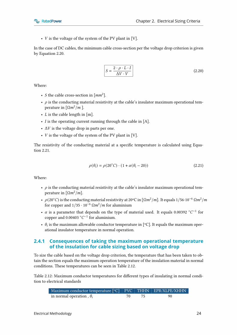
In the case of DC cables, the minimum cable cross-section per the voltage drop criterion is givenby Equation 2.20.
( =2 · d · ! · �Δ+ ·+ (2.20)
Where:
• ( the cable cross-section in [<<2].• d is the conducting material resistivity at the cable’s insulator maximum operational tem-
perature in [Ω<2/< ].• ! is the cable length in [m].• � is the operating current running through the cable in [A].• Δ+ is the voltage drop in parts per one.• + is the voltage of the system of the PV plant in [V].
The resistivity of the conducting material at a speci�c temperature is calculated using Equa-tion 2.21.
d (\ i) = d (20◦�) · (1 + U (\ i − 20)) (2.21)
Where:
• d is the conducting material resistivity at the cable’s insulator maximum operational tem-perature in [Ω<2/<].
• d (20◦�) is the conducting material resistivity at 20ºC in [Ω<2/<]. It equals 1/56·10−6 Ω<2/<for copper and 1/35 · 10−6 Ω<2/< for aluminium
• U is a parameter that depends on the type of material used. It equals 0.00392 ◦�−1 forcopper and 0.00403 ◦�−1 for aluminium.
• \ i is the maximum allowable conductor temperature in [ºC]. It equals the maximum oper-ational insulator temperature in normal operation.
2.4.1 Consequences of taking the maximum operational temperatureof the insulation for cable sizing based on voltage drop
To size the cable based on the voltage drop criterion, the temperature that has been taken to ob-tain the section equals the maximum operation temperature of the insulation material in normalconditions. These temperatures can be seen in Table 2.12.
Table 2.12: Maximum conductor temperatures for di�erent types of insulating in normal condi-tion to electrical standards
Maximum conductor temperature [ºC] PVC THHN EPR/XLPE/XHHNin normal operation , \ i 70 75 90
Electrical Methodology 24

Chapter 2. Electrical Sizing Criteria
Sometimes, this temperature is taken as the maximum ambient temperature: 30 ºC or 35 ºC.This decision can cause up to 25% error when sizing a cable. Taking the maximum operationaltemperature causes more conservative results as it is seen in Figure 2.3.
Figure 2.3: Al XLPE cable cross-section based on resistivities at di�erent temperatures [<<2].Source: Own elaboration.
2.4.2 Consequences of taking the AC resistance equals to the DC resis-tance
There is a slight di�erence between the DC cable resistance and the AC cable resistance. Thelatest is a�ected by the skin e�ect and the proximity of other conductors. The AC resistance iscalculated using Equation 2.22. [12]
'AC = 'DC · (1 + ~s + ~p) (2.22)
Where:
• 'AC is the AC cable resistance Ω/<.• 'DC is the DC cable resistance Ω/<.• ~s represents the skin e�ect.• ~p represents how other close conductors a�ect the cable.
Considering that the DC cable resistance equals to the AC cable resistance can produce a maxi-mum of 7% error for sections from 300 to 630<<2. For sections lower than 300<<2, this erroris negligible. Taking both resistances as equal gives less conservative results as it is seen inFigure 2.4 and Figure 2.5.
Electrical Methodology 25

Chapter 2. Electrical Sizing Criteria
Figure 2.4: AC and DC resistivities for a Cu cable based on IEC. Source: Own elaboration.
Figure 2.5: AC and DC resistivities for a Cu cable based on Tables 8 and 9 of the NEC standard.Source: Own elaboration.
2.4.3 Consequences of not considering the reactive powerThe formula to calculate the cross-section of a cable taking into account the reactance in a ACsystem is given by Equation 2.23.
Electrical Methodology 26

Chapter 2. Electrical Sizing Criteria
( =
√3 · d · ! · � · 2>Bi
Δ+ −√3 · G/= · ! · � · B8=i
(2.23)
Where:
• ( the cable cross-section in [<<2].• ! is the cable length in [m].• � is the operating current running through the cable in [A].• Δ+ is the voltage drop in parts per one.• d is the conducting material resistivity at the cable’s insulator maximum operational tem-
perature in [Ω<2/< ].• G is the reactance of the cable in [Ω/<].• = is the number of conductor per phase.
At this moment, pvDesign is not able to size the cable using the cosine of phi. For that reason, astudy about how the reactance of the line will a�ect the selection of the cross-section of Al andCu cables has been performed. A reactance of 0.08 Ω/:< has been selected.
In Figure 2.6 and Figure 2.7, the results that have been presented show the increase of sectionthat would be necessary if the reactance of the line is considered in comparison with the sectionsobtained using Equation 2.19.
Hence, it is recommended to rise the allowed voltage drop for MV lines as the PV plant surfaceincreases in order to have more realistic cross-sections. In conclusion, not taking into accountthe reactance of the line implies less conservative results.
Figure 2.6: Average increase of cross-sections for Al cables considering di�erent voltage dropsfor cos phi = 0.95, 0.9 and 0.85, and di�erent cable lengths. Source: Own elaboration
Electrical Methodology 27

Chapter 2. Electrical Sizing Criteria
Figure 2.7: Average increase of cross-sections for Cu cables considering di�erent voltage dropsfor cos phi = 0.95, 0.9 and 0.85, and di�erent cable lengths. Source: Own elaboration
Electrical Methodology 28

Bibliography
Bibliography
[1] Technical Committee 84, “Photovoltaic (pv) arrays - design requirements,” InternationalElectrotechnical Commision, IEC 62548:2016, 2016.
[2] National Electrical Code Committee, “Nfpa 70 national electrical code,” International Stan-dard, 2017.
[3] Technical Committee 82, “Ground-mounted photovoltaic power plants - design guidelinesand recommendations,” International Electrotechnical Commision, IEC TS 62738:2018, 2018.
[4] Technical Committee 20, “Power cables with extruded insulation and their accessories forrated voltages from 1 kv (um = 1,2 kv) up to 30 kv (um = 36 kv) - part 2: Cables for ratedvoltages from 6 kv (um = 7,2 kv) up to 30 kv (um = 36 kv),” International ElectrotechnicalCommision, IEC 60502-2:2014, 2014.
[5] Technical Committee 64, “Low-voltage electrical installations - part 5-52: Selection anderection of electrical equipment - wiring systems,” International Electrotechnical Commi-sion, IEC 60364-5-52:2009, 2009.
[6] EL-001, “Electrical installations. selection of cables cables for alternating voltages up toand including 1 kv. typical australian installation conditions,” Standards Australia, AS3008.1.1:2017, 2017.
[7] Prysmian Australia Pty Ltd, “Medium voltage cables,” Technical report, 2015.
[8] “Standard for design of cables of electric power engineering,” National Standard of thePeople’s Republic of China, GB 50217-2018, 2018.
[9] Prysmian Group, “Manual tecnico y practico de cables y accesorios para media tension,”White paper, 2008.
[10] Technical Committee 20, “Calculation of thermally permissible short-circuit currents, tak-ing into account non-adiabatic heating e�ects,” International Electrotechnical Commision,IEC 60949:1988, 1988.
[11] RatedPower, “Substation methodology. a methodology to design an air-insulated substa-tion,” RatedPower, 2020.
[12] Technical Committee 20, “Electric cables - calculation of the current rating - part 1-1: Cur-rent rating equations and calculation of losses - general,” International ElectrotechnicalCommision, IEC 60287-1-1:2006, 2006.
[13] IEEE, “IEEE Recommended Practice for Industrial and Commercial Power Systems Anal-ysis,” no. IEEE Std 399-1997, 1997.
Electrical Methodology 29

Bibliography
[14] Technical Committee 20, “Electric cables - calculation of the current rating - part 3-1: Op-erating conditions - site reference conditions,” International Electrotechnical Commision,IEC 60287-3-1:2017, 2017.
[15] Technical Committee 64, “Low-voltage electrical installations - part 5-54: Selection anderection of electrical equipment - earthing arrangements and protective conductors,” In-ternational Electrotechnical Commision, IEC 60364-5-54:2011, 2006.
Electrical Methodology 30

Appendix A. Determining cable cross-sections
Appendix A
Determining cable cross-sections
The assumptions made for the following examples are the following ones:
• The soil temperature equals 25°C.• The ambient temperature equals 40°C.• The soil resistivity equals 1 Km/W.• The depth of cables are 700 mm for buried LV cables and 900 mm for MV cables.• The MV cables are spaced 0.2 m between group centres and there is no space between LV
cables.• String cables are single core Cu cables fastened to the structures. XLPE is chosen for IEC
and XHHN for NEC.• Medium voltage cables are single core Al cables directly buried in trenches. XLPE is chosen
for IEC and XHHN for NEC.• The voltage drop is considered as 0.5 % for LV and MV cables.
A.1 Medium voltage cablesThe power of the cable is 12 MVA. The voltage level is 30 kV and the length is 500 m. In addition,there are 10 lines that are grouped together to connect the plant with the substation. The short-circuit current equals 25 kA and the short-circuit time equals 1 s.
A.1.1 IEC standardThe operating current is calculated as:
�load =(VA
+ ·√3=
12 · 106
30 · 103 ·√3= 230� (A.1)
The IEC standard followed to size a medium voltage cable is the IEC 60502-2. The referenceconditions that the IEC standard takes as basis for its tables are the following ones:
• A maximum conductor temperature of 90 °C
Electrical Methodology 31

Appendix A. Determining cable cross-sections
• An ambient air temperature of 30 °C• A ground temperature of 20 °C• A depth of laying of 0.8 m• A thermal resistivity of soil of 1.5 Km/W
As the medium voltage cable is directly buried, the ground temperature correction factor is givenby Equation 2.3. The conductor is aluminium whose V equals 228 ºC. The insulator material isXLPE whose operational temperature in normal conditions is \ i = 90 ºC.
��temp =
[\ i − \a
\ ′i − \ ′a·V + \ ′iV + \ i
] 12
=
[90 − 2590 − 20 ·
228 + 90228 + 90
] 12
= 0.928 (A.2)
The other corrections factors are given in the following table. In order to �nd them in the tables,there are few parameters that need to be taken into account.
First of all, this medium voltage cable is a single core cable. There are 10 circuits that are groupedtogether to link the power stations to the substations. In this case, according to IEC, a value of10 current-carrying conductors should be considered to obtain the correction factor for a groupof cables. Second, the cable is installed at a depth of 0.9 m and they are spaced 0.2 m betweengroup centres. Last, the soil resistivity that is considered is equal to 1 Km/W.
Table A.1: Correction factors according to IEC standard for MV cables.
Correction Factors For MV cables:IEC 60502-2
Correction factors
For soil thermal resistivities Table B.14 ≈ 1.19For depths of laying Table B.12 ≈ 0.975For groups of cables Table B.19 0.54
Then, the sizing current is given by Equation 2.2.
�sizing =�operating
��=
2300.928 · 1.19 · 0.975 · 0.54 =
2300.58
= 395� (A.3)
According to table B.3 of the IEC standard, the section chosen is 300<<2.
( = 300<<2 ⇒ �ccc = 414� > �sizing = 395� (A.4)
According to the short-circuit current criterion, the section is obtained using Equation 2.11. Theshort-circuit temperature of the XLPE is 250 ºC.
( =�sc ·√C
·
√;=
(\f + V\ i + V
) =25000 ·
√1
148 ·
√;=
(250 + 22890 + 228
) = 266<<2 (A.5)
Electrical Methodology 32

Appendix A. Determining cable cross-sections
According to the voltage drop criterion, the section is obtained using Equation 2.19.
( =
√3 · d (20◦�) · (1 + U (\ i − 20)) · ! · �
Δ+ ·+ =
√3 · 1/35 · (1 + 0.00403(90 − 20)) · 500 · 230
0.005 · 30000 = 48<<2
(A.6)
Finally, the section of the cable is given by the following expression:
( =<0G(300<<2, 266<<2, 48<<2) = 300<<2 (A.7)
A.1.2 NEC standardThe operating current is calculated as:
�load =(VA
+ ·√3=
12 · 106
30 · 103 ·√3= 230� (A.8)
The reference conditions that the NEC standard takes as basis for its tables of MV cables are thefollowing ones:
• A maximum conductor temperature of 90 °C• An ambient air temperature of 40 °C• A ground temperature of 20 °C• A depth of laying of 0.9 m• A thermal resistivity of soil of 0.9 Km/W
As the medium voltage cable is directly buried, the ground temperature correction factor is givenby Equation 2.3. The conductor is aluminium whose V equals 228 ºC. The insulator material isXHHN whose operational temperature in normal conditions is \ i = 90 ºC.
��temp =
[\ i − \a
\ ′i − \ ′a·V + \ ′iV + \ i
] 12
=
[90 − 2590 − 20 ·
228 + 90228 + 90
] 12
= 0.928 (A.9)
The other corrections factors are given in the following table. In order to �nd them in the tables,there are few parameters that need to be taken into account.
First of all, this medium voltage cable is a single core cable. There are 10 circuits that are groupedtogether to link the power stations to the substations. In this case, according to NEC, a value of30 current-carrying conductors should be considered to obtain the correction factor for a groupof cables. Second, the cable is installed at a depth of 0.9 m and they are spaced 0.2 m betweengroup centres. Last, the soil resistivity that is considered is equal to 1 Km/W.
Electrical Methodology 33

Appendix A. Determining cable cross-sections
Table A.2: Correction factors according to NEC standard for MV cables.
Correction Factors For MV cables:NEC
Correction factors
For soil thermal resistivities IEEE Std 399-1997 - Table 13-7 ≈ 0.91For depths of laying NEC Annex B, Section B.3(b) 1For groups of cables NEC Table B.310.15(B)(2)(11) 0.6
Then, the sizing current is given by Equation 2.6.
�sizing =�operating
��=
2300.928 · 0.91 · 1 · 0.6 = 453� (A.10)
According to table 310.60(C)(86) of the NEC standard, the section chosen is 750 kcmil.
( = 750:2<8; ⇒ �ccc = 550� > �sizing = 453� (A.11)
According to the short-circuit current criterion, the section is obtained using Equation 2.11. Theshort-circuit temperature of the XHHN is 250 ºC.
( =�sc ·√C
·
√;=
(\f + V\ i + V
) =25000 ·
√1
148 ·
√;=
(250 + 22890 + 228
) = 266<<2 (A.12)
According to the voltage drop criterion, the section is obtained using Equation 2.19.
( =
√3 · d (20◦�) · (1 + U (\ i − 20)) · ! · �
Δ+ ·+ =
√3 · 1/35 · (1 + 0.00403(90 − 20)) · 500 · 230
0.005 · 30000 = 48<<2
(A.13)
Finally, the section of the cable is given by the following expression:
( =<0G(750:2<8;, 266<<2, 48<<2) = 750:2<8; ≈ 380<<2 (A.14)
A.2 Low voltage cables. String levelThe power of the string is 10.585 kW. The MPP voltage is 1145 V and the length is 30 m. Inaddition, there are 24 strings that are grouped together to connect the structures to a string box.The short-circuit current of the modules equals 9.75 A.
A.2.1 IEC standardThe operating current is calculated as:
Electrical Methodology 34

Appendix A. Determining cable cross-sections
�load =(VA
+ ·√3=10.585 · 103
1145· = 9.24� (A.15)
The IEC standard followed to size a low voltage cable is the IEC 60364-5-52. The reference con-ditions that the IEC standard takes as basis for its tables are the following ones:
• A maximum conductor temperature of 90 °C for XLPE and 70 ºC for PVC.• An ambient air temperature of 30 °C• A ground temperature of 20 °C• The depth of laying is not considered.• A thermal resistivity of soil of 2.5 Km/W
As the low voltage cable is fastened to a structure, the ambient temperature correction factor isgiven by Equation 2.3. The conductor is copper whose V equals 234.5 ºC. The insulator materialis XLPE whose operational temperature in normal conditions is \ i = 90 ºC.
��temp =
[\ i − \a
\ ′i − \ ′a·V + \ ′iV + \ i
] 12
=
[90 − 4090 − 30 ·
234.5 + 90234.5 + 90
] 12
= 0.83 (A.16)
The other corrections factors are given in the following table. In order to �nd them in the tables,there are few parameters that need to be taken into account.
First of all, this low voltage cable is a single core cable. There are 24 circuits that are groupedtogether to link the structures to a string box. In this case, according to IEC, a value of 24 current-carrying conductors should be considered to obtain the correction factor for a group of cables.Second, the cable is fastened to a structure and they are touching among each other.
Table A.3: Correction factors according to IEC standard for LV cables.
Correction Factors For MV cables:IEC 60502-2
Correction factors
For groups of cables Table B.52.17 0.72
Then, the sizing current is given by Equation 2.2.
�sizing =�operating
��=
9.240.833 · 0.72 = 15.4� (A.17)
According to table B.52.12 of the IEC standard, the section chosen is 1.5<<2.
( = 1.5<<2 ⇒ �ccc = 29� > �sizing = 15.4� (A.18)
According to the voltage drop criterion, the section is obtained using Equation 2.20.
Electrical Methodology 35

Appendix A. Determining cable cross-sections
( =2 · d (20◦�) · (1 + U (\ i − 20)) · ! · �
Δ+ ·+ =2 · 1/56 · (1 + 0.00392(90 − 20)) · 30 · 15.4
0.005 · 1145 = 3.7<<2
(A.19)
Finally, the section of the cable is given by the following expression:
( =<0G(1.5<<2 , 3.7<<2) = 3.7<<2 ⇒ 4<<2 (2><<4A280; B42C8>=) (A.20)
A.2.2 NEC standardThe sizing current is calculated by Equation 2.5.
�sizing =<0G (�corrected , �OCPD) (A.21)
The reference conditions that the NEC standard takes as basis for its tables of LV cables are thefollowing ones:
• A maximum conductor temperature of 90 °C for XHHN insulation and 75 ºC for THHNinsulation.
• An ambient air temperature of 30 °C• A ground temperature of 20 °C• A thermal resistivity of soil of 0.9 Km/W
As the low voltage cable is fastened to a structure, the ambient temperature correction factor isgiven by Equation 2.3. The conductor is copper whose V equals 234.5 ºC. The insulator materialis XHHN whose operational temperature in normal conditions is Cℎ4C0i = 90 ºC.
��temp =
[\ i − \a
\ ′i − \ ′a·V + \ ′iV + \ i
] 12
=
[90 − 4090 − 30 ·
234.5 + 90234.5 + 90
] 12
= 0.83 (A.22)
The other corrections factors are given in the following table. In order to �nd them in the tables,there are few parameters that need to be taken into account.
First of all, this low voltage cable is a single core cable. There are 24 circuits that are groupedtogether to link the structures to a string box. In this case, according to NEC, a value of 48current-carrying conductors should be considered to obtain the correction factor for a group ofcables. Second, the cable is fastened to a structure and they are touching among each other.
Table A.4: Correction factors according to NEC standard for LV cables.
Correction Factors For MV cables:NEC
Correction factors
For groups of cables NEC Table B.310.15(B)(2)(11) 0.5
Then, the corrected current is given by Equation 2.6.
Electrical Methodology 36

Appendix A. Determining cable cross-sections
�corrected =1.25 · �sc
��=1.25 · 9.750.83 · 0.5 = 29� (A.23)
On the other hand, the �OCPD is calculated based on Equation 2.7.
1.25 · (1.25 · �sc) = 1.56 · 9.75 = 15.21�⇒ �OCPD = 20� (A.24)
Then, the sizing current is calculated as:
�sizing =<0G (29� , 20�) = 29� (A.25)
According to table 310.15(B)(17) of the NEC standard, the section chosen is 14 AWG.
( = 14�,� ⇒ �ccc = 35� > �sizing = 29� (A.26)
According to the voltage drop criterion, the section is obtained using Equation 2.20.
( =2 · d (20◦�) · (1 + U (\ i − 20)) · ! · �
Δ+ ·+ =2 · 1/56 · (1 + 0.00392(90 − 20)) · 30 · 15.4
0.005 · 1145 = 3.7<<2
(A.27)
Finally, the section of the cable is given by the following expression:
( =<0G(14�,� , 3.7<<2) = 3.7<<2 ⇒ 10�,� (2><<4A280; B42C8>=) (A.28)
Electrical Methodology 37

Appendix B. Determining electrical characteristics of the cable
Appendix B
Determining electricalcharacteristics of the cable
After selecting the cross-section based on the three criteria that have been presented in thismethodology, the electrical characteristics of the cable are computed. These are the voltage drop,the temperature and the short-circuit current that the cables can withstand.
B.1 Determining the electrical characteristics of a mediumvoltage cable
The following example is based on the cable that was calculated in Subsection A.1.1. At the end,the cable cross-section was 300<<2.
B.1.1 Temperature of the cableThe temperature of the cable is calculated using Equation 2.8.
\ = \amb + (\ i − \amb) ·(�
�a
)2(B.1)
\ = 25 + (90 − 25) ·(
230414 · 0.58
)2= 84 ◦� < \ i = 90 ◦� ⇒ $ (B.2)
B.1.2 Voltage dropThe voltage drop is calculated using the following formula:
Δ+ =
√3 · d (20◦�) · (1 + U (84◦� − 20)) · ! · �
( ·+ (B.3)
Δ+ =
√3 · 0.0359 · 500 · 230
300 · 30000 = 0.08% < Δ+input = 0.5%⇒ $ (B.4)
Electrical Methodology 38

Appendix B. Determining electrical characteristics of the cable
B.1.3 Withstand short-circuit currentThe withstand short-circuit current that the cable can withstand is calculated as follows:
�sc =
( · ·
√;=
(\f + V\ i + V
)√C
(B.5)
�sc =
300 · 148 ·
√;=
(250 + 22890 + 228
)√1
= 28.2:� > �sc grid = 25:�⇒ $ (B.6)
Electrical Methodology 39