Embed Size (px)
Citation preview
Electric Actuator/Slider TypeBall Screw Drive
Series 25A-LEFSLEFS16, 25, 32, 40
Step Motor (Servo/24 VDC) Servo Motor (24 VDC)
Applicable stroke table Standard
50 100 150 200 250 300 350 400 450 500 550 600 650 700 750 800 850 900 950 1000 Manufacturablestroke range [mm]
LEFS16 — — — — — — — — — — 50 to 500
LEFS25 — — — — — — — — 50 to 600
LEFS32 — — — — 50 to 800
LEFS40 — — 150 to 1000
* Strokes are manufacturable in 1 mm increments. Refer to the manufacturable stroke range. However, strokes other than those shown above are produced as special orders. Consult with SMC for lead times and prices.
How to Order
r Motor type
Symbol TypeApplicable size Compatible
controllers/driverLEFS16 LEFS25 LEFS32 LEFS40
Nil Step motor(Servo/24 VDC)
LECP6LECP1LECPA
LECPMJ
A Servo motor(24 VDC) — — LECA6
t Lead [mm]Symbol LEFS16 LEFS25 LEFS32 LEFS40
A 10 12 16 20B 5 6 8 10
e Motor mounting positionNil In-lineR Right side parallelL Left side parallel
w Size16253240
y Stroke [mm]50 50to to
1000 1000
* Refer to the applicable stroke table.
ModelStroke
[mm]
Caution[CE-compliant products]qEMC compliance was tested by combining the electric actuator LEF series and the controller
LEC series.The EMC depends on the configuration of the customer’s control panel and the relationship with other electrical equipment and wiring. Therefore conformity to the EMC directive cannot be certified for SMC components incorporated into the customer’s equipment under actual operating conditions. As a result it is necessary for the customer to verify conformity to the EMC directive for the machinery and equipment as a whole.
wFor the servo motor (24 VDC) specification, EMC compliance was tested by installing a noise filter set (LEC-NFA).Refer to the WEB catalog for the noise filter set. Refer to the LECA Operation Manual for installation.
[UL-compliant products]When conformity to UL is required, the electric actuator and controller/driver should be used with a UL1310 Class 2 power supply.
Series compatible withsecondary batteries
The actuator and controller/driver are sold as a package.Confirm that the combination of the controller/driver and the actuator is correct.
<Check the following before use.>qCheck the actuator label for model number (after "25A-"). This matches the controller/driver.
wCheck Parallel I/O configuration matches (NPN or PNP).
* Refer to the operation manual for using the products. Please download it via our website, http://www.smcworld.com
RoHS
®
q w
q AccuracyNil Basic typeH High precision type
25A-LEFS 25w
200y
6N!0
Si
1o
Re
Hq r
Bt u
1!1 !2
153
25A-P-B-P153-web修正-CS3e.indd 153 14.10.10 5:01:34 PM
A

u Motor optionNil Without optionB With lock
i Actuator cable type*1
Nil Without cableS Standard cable*2
R Robotic cable (Flexible cable)
*1 The standard cable should be used on fixed parts. For using on moving parts, select the robotic cable.
*2 Only available for the motor type “Step motor”.
!1 I/O cable length [m]*1, Communication plugNil Without cable (Without communication plug connector*3)1 1.53 3*2
5 5*2
S Straight type communication plug connector*3
T T-branch type communication plug connector*3
*1 When “Without controller/driver” is selected for controller/driver types, I/O cable cannot be selected. When the I/O cable is required, order it separately.
*2 When “Pulse input type” is selected for controller/driver types, pulse input usable only with differential. Only 1.5 m cables usable with open collector.
*3 When “CC-Link direct input type” is selected for controller/driver types, I/O cable is not included. Only “Nil”, “S” or “T” can be selected.
!2 Controller/Driver mountingNil Screw mountingD DIN rail mounting*
* DIN rail is not included. Order it separately.
o Actuator cable length [m]Nil Without cable 1 1.53 35 58 8*
A 10*
B 15*
C 20*
* Produced upon receipt of order (Robotic cable only)
!0 Controller/Driver type*1
Nil Without controller/driver6N LECP6/LECA6
(Step data input type)NPN
6P PNP1N LECP1*2
(Programless type)NPN
1P PNP
MJ LECPMJ*2 *3
(CC-Link direct input type) —
AN LECPA*2 *4
(Pulse input type)NPN
AP PNP
*1 For details about controllers/driver and compatible motors, refer to the compatible controllers/driver below.
*2 Only available for the motor type “Step motor”.*3 Not applicable to CE.*4 When pulse signals are open collector, order
the current limit resistor (LEC-PA-R-l) separately.
Compatible Controllers/Driver
Type
Step datainput type
Step datainput type
CC-Link direct input type
Programless type Pulse input type
Series LECP6 LECA6 LECPMJ LECP1 LECPA
FeaturesValue (Step data) input
Standard controllerCC-Link direct input
Capable of setting up operation (step data) without using a PC or teaching box
Operation by pulse signals
Compatible motorStep motor
(Servo/24 VDC)Servo motor
(24 VDC)Step motor
(Servo/24 VDC)
Maximum number of step data 64 points 64 points 14 points —
Power supply voltage 24 VDC
* Copper and zinc materials are used for the motors, cables, controllers/drivers.
* Specifications and dimensions for the 25A-series are the same as standard products.
Motor mounting position: Right side parallel
Motor mounting position: In-line
154
Electric Actuator/Slider TypeBall Screw Drive Series 25A-LEFS
25A-P-B-P154-web修正-CS3e.indd 154 14.10.9 7:30:15 PM
Air C
ylin
ders
Air
Grip
pers
Dire
ctio
nal
Cont
rol V
alve
sR
elat
edP
rod
uct
sR
ota
ryA
ctu
ato
rsV
acuu
mE
quip
men
tAi
r Pre
para
tion
Equi
pmen
tAir
Filte
rs/Pre
ssure
Contr
ol Eq
uipme
ntFit
tings
/Flow
Contr
ol Eq
uipme
ntD
etec
tio
nS
wit
ches
Flui
d Co
ntro
lEq
uipm
ent
Ele
ctri
cA
ctu
ato
rsA
uto
Sw
itch
esC
lean
Air
Filt
ers
A
Electric Actuator/Slider TypeBall Screw Drive
Series 25A-LEFSLEFS25, 32, 40
How to Order
RoHS
!0 Driver typeCompatible
driversPower supply
voltage (V)Size
25 32 40Nil Without driver — A1 LECSA1-S 100 to 120 —A2 LECSA2-S 200 to 230 B1 LECSB1-S 100 to 120 —B2 LECSB2-S 200 to 230 C1 LECSC1-S 100 to 120 —C2 LECSC2-S 200 to 230 S1 LECSS1-S 100 to 120 —S2 LECSS2-S 200 to 230
* When the driver type is selected, the cable is included. Select cable type and cable length.Example) S2S2: Standard cable (2 m) + Driver (LECSS2)
S2 : Standard cable (2 m)Nil : Without cable and driver
AC Servo Motor
Series compatible withsecondary batteries
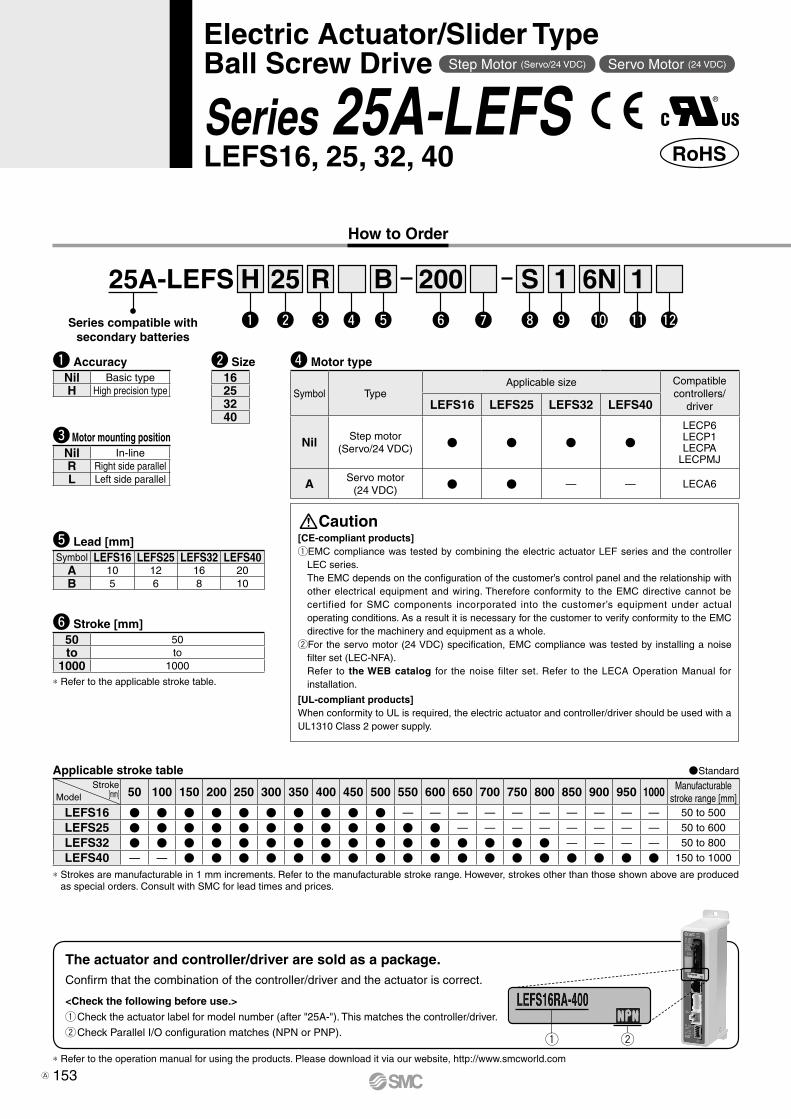
Applicable stroke table Standard
50 100 150 200 250 300 350 400 450 500 550 600 650 700 750 800 850 900 950 1000Manufacturable
stroke range[mm]
LEFS25 — — — — — — — — 50 to 600
LEFS32 — — — — 50 to 800
LEFS40 — — 150 to 1000
* Strokes are manufacturable in 1 mm increments. Refer to the manufacturable stroke range. However, strokes other than those shown above are produced as special orders. Consult with SMC for lead times and prices.
Model
Stroke[mm]
r Motor typeSymbol Type Output [W] Actuator size Compatible driversS2*1 AC servo motor
(Incrementalencoder)
100 25 LECSA-S1S3 200 32 LECSA-S3S4 400 40 LECSA2-S4
S6*1
AC servo motor(Absoluteencoder)
100 25LECSB-S5LECSC-S5LECSS-S5
S7 200 32LECSB-S7LECSC-S7LECSS-S7
S8 400 40LECSB2-S8LECSC2-S8LECSS2-S8
*1 For motor type “S2” and “S6”, the compatible driver part number suffixes are “S1” and “S5” respectively.
*2 For details about the driver, refer to the WEB catalog.
e Motor mounting position
Nil In-lineR Right side parallelL Left side parallel
i Cable type*1, *2
Nil Without cableS Standard cable
R Robotic cable(Flexible cable)
*1 The motor and encoder cables are included. (The lock cable is also included when the motor with lock option is selected.)
*2 Standard cable entry direction is· Parallel: (A) Axis side· In-line: (B) Counter axis side
w Size253240
t Lead [mm]Symbol LEFS25 LEFS32 LEFS40
A 12 16 20B 6 8 10
o Cable length* [m]Nil Without cable2 25 5A 10
* The length of the encoder, motor and lock cables are the same.
u Motor optionNil Without optionB With lock
y Stroke [mm]50 50to to
1000 1000
* Refer to the applicable stroke table.
* Specifications and dimensions for the 25A-series are the same as standard products.
!1 I/O cable length [m]*3
Nil Without cableH Without cable (Connector only)1 1.5
*3 When “Without driver” is selected for driver type, only “Nil: Without cable” can be selected.Refer to the WEB catalog if I/O cable is required.
25A-LEFS 32w
Re
Hq
S3r
200y
A2!0
Si
2o
Bt u !1
q AccuracyNil Basic typeH High precision type
155
Compatible Drivers
Driver type
Pulse input type/Positioning type
Pulse input type CC-Link direct input type
SSCNET# type
Series LECSA LECSB LECSC LECSSNumber of point tables Up to 7 — Up to 255 (2 stations occupied) —Pulse input — —Applicable network — — CC-Link SSCNET3
Control encoder Incremental17-bit encoder
Absolute18-bit encoder
Absolute18-bit encoder
Absolute18-bit encoder
Communication function USB communication USB communication, RS422 communication USB communication, RS422 communication USB communication
Power supply voltage (V)100 to 120 VAC (50/60 Hz)200 to 230 VAC (50/60 Hz)
* Copper and zinc materials are used for the motors, cables, controllers/drivers.
25A-P-B-P155-web修正-CS3e.indd 155 14.10.10 5:02:30 PM
A

Series compatible withsecondary batteries
* Specifications and dimensions for the 25A-series are the same as standard products.
AC Servo Motor
How to Order
156
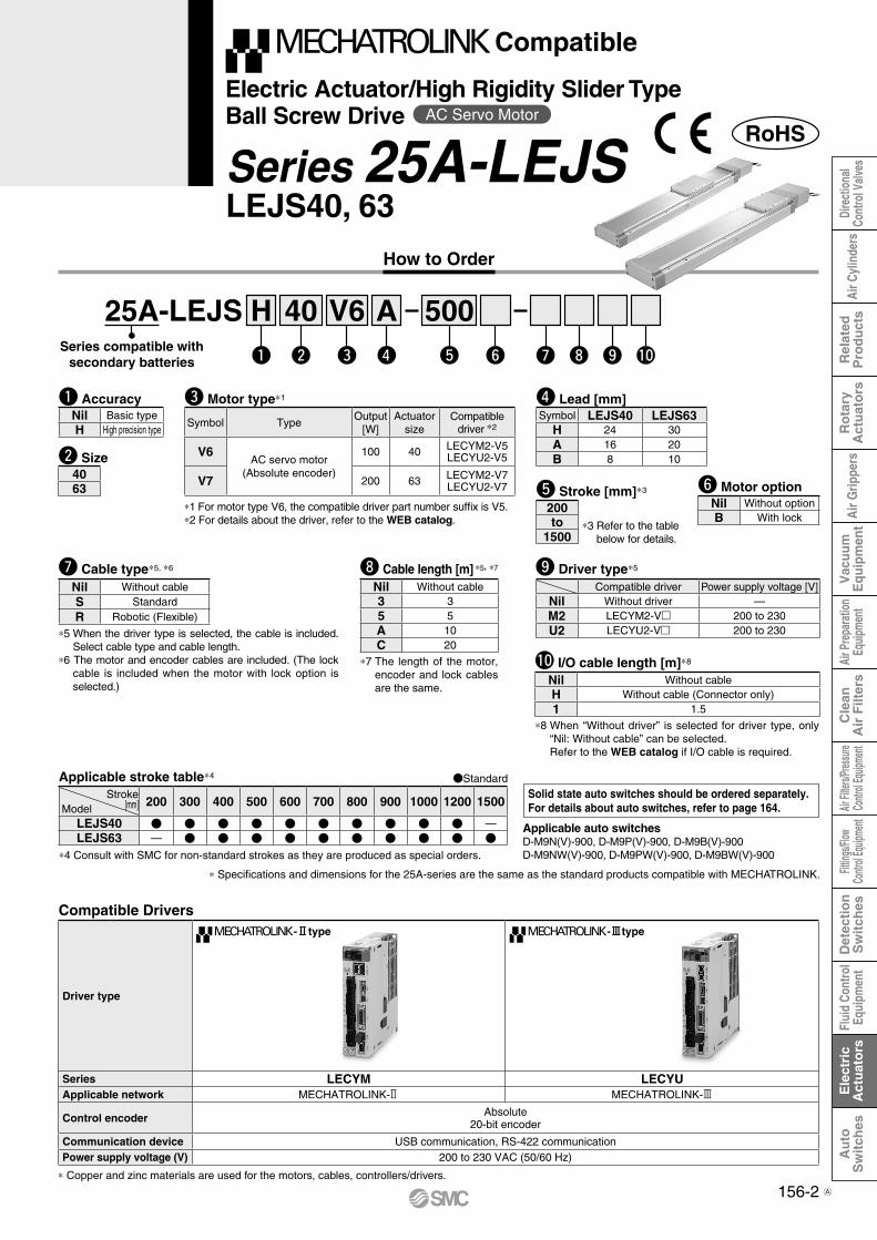
Electric Actuator/High Rigidity Slider TypeBall Screw Drive
Series 25A-LEJSLEJS40, 63
Compatible Drivers
Solid state auto switches should be ordered separately.For details about auto switches, refer to page 164.
Applicable stroke table*4 Standard
*4 Consult with SMC for non-standard strokes as they are produced as special orders.
*1 For motor type “S2” and “S6”, the compatible driver part number suffixes are “S1” and “S5” respectively.
*2 For details about the driver, refer to the WEB catalog.
w Size
*6 The motor and encoder cables are included. (The lock cable is included when the motor with lock option is selected.)
*7 Standard cable entry is “(A) Axis side”.
*8 The length of the motor, encoder and lock cables are the same.
u Cable type*5, *6, *7
i Cable length [m]*5, *8
e Motor type*1
o Driver type*5
*5 When the driver type is selected, the cable is included. Select cable type and cable length.Example)S2S2: Standard cable (2 m) +
Driver (LECSS2)S2 : Standard cable (2 m)Nil : Without cable and driver
Applicable auto switchesD-M9N(V)-900, D-M9P(V)-900, D-M9B(V)-900D-M9NW(V)-900, D-M9PW(V)-900, D-M9BW(V)-900
RoHS
Compatible drivers Power supply voltage (V)Nil Without driver —A1 LECSA1-S 100 to 120A2 LECSA2-S 200 to 230B1 LECSB1-S 100 to 120B2 LECSB2-S 200 to 230C1 LECSC1-S 100 to 120C2 LECSC2-S 200 to 230S1 LECSS1-S 100 to 120S2 LECSS2-S 200 to 230
Symbol TypeOutput
[W]Actuator
sizeCompatibledrivers *2
S2 AC servo motor(Incremental encoder)
100 40 LECSA-S1
S3 AC servo motor(Incremental encoder)
200 63 LECSA-S3
S6 AC servo motor(Absolute encoder)
100 40LECSB-S5LECSC-S5LECSS-S5
S7 AC servo motor(Absolute encoder)
200 63LECSB-S7LECSC-S7LECSS-S7
Nil Without cableS Standard cableR Robotic cable (Flexible cable)
Nil Without cable2 25 5A 10
*3 Refer to the table below for details.
t Stroke [mm]*3
200to
1500
Stroke[mm]Model
200 300 400 500 600 700 800 900 1000 1200 1500
LEJS40 —LEJS63 —
y Motor optionNil Without optionB With lock
r Lead [mm]Symbol LEJS40 LEJS63
H 24 30A 16 20B 8 10
4063
Driver type
Pulse input type/Positioning type
Pulse input type CC-Link directinput type
SSCNET# type
Series LECSA LECSB LECSC LECSSNumber of point tables Up to 7 — Up to 255 —Pulse input — —Applicable network — — CC-Link SSCNET3
Control encoder Incremental17-bit encoder
Absolute18-bit encoder
Absolute18-bit encoder
Absolute18-bit encoder
Communication function USB communication USB communication, RS422 communication USB communication, RS422 communication USB communication
Power supply voltage (V)100 to 120 VAC (50/60 Hz)200 to 230 VAC (50/60 Hz)
* Copper and zinc materials are used for the motors, cables, controllers/drivers.
25A-LEJS 40 500AHw e rq t y u i o !0
q Accuracy
S2
Nil Basic typeH High precision type
!0 I/O cable length [m]*9
Nil Without cableH Without cable (Connector only)1 1.5
*9 When “Without driver” is selected for driver type, only “Nil: Without cable” can be selected.Refer to the WEB catalog if I/O cable is required.
25A-P-B-P156-web修正-CS3e.indd 156 14.10.9 8:40:31 PM
Air C
ylin
ders
Air
Grip
pers
Dire
ctio
nal
Cont
rol V
alve
sR
elat
edP
rod
uct
sR
ota
ryA
ctu
ato
rsV
acuu
mE
quip
men
tAi
r Pre
para
tion
Equi
pmen
tAir
Filte
rs/Pre
ssure
Contr
ol Eq
uipme
ntFit
tings
/Flow
Contr
ol Eq
uipme
ntD
etec
tio
nS
wit
ches
Flui
d Co
ntro
lEq
uipm
ent
Ele
ctri
cA
ctu
ato
rsA
uto
Sw
itch
esC
lean
Air
Filt
ers
A

Series compatible withsecondary batteries
How to Order
156-1
Electric Actuator/High Rigidity Slider TypeBall Screw Drive
Series 25A-LEJSAC Servo Motor
LEJS40, 63
Compatible
Compatible Drivers
Driver type
type
Series LECSS-TApplicable network SSCNET3/H
Control encoderAbsolute
22-bit encoder
Communication function USB communicationPower supply voltage (V) 200 to 240 VAC (50/60Hz)
* Copper and zinc materials are used for the motors, cables, controllers/drivers.
Solid state auto switches should be ordered separately.For details about auto switches, refer to page 164.
Applicable stroke table*4 Standard
*4 Consult with SMC for non-standard strokes as they are produced as special orders.
Applicable auto switchesD-M9N(V)-900, D-M9P(V)-900, D-M9B(V)-900D-M9NW(V)-900, D-M9PW(V)-900, D-M9BW(V)-900
RoHS
e Motor type*1
Symbol TypeOutput
[W]Actuator
sizeCompatible
driver *2
T6 AC servo motor(Absolute encoder)
100 40 LECSS2-T5T7 200 63 LECSS2-T7
*1 For motor type T6, the compatible driver part number suffix is T5.*2 For details about the driver, refer to the WEB catalog.
*3 Refer to the table below for details.
t Stroke [mm]*3
200to
1500
Stroke[mm]Model
200 300 400 500 600 700 800 900 1000 1200 1500
LEJS40 —LEJS63 —
y Motor optionNil Without optionB With lock
r Lead [mm]Symbol LEJS40 LEJS63
H 24 30A 16 20B 8 10w Size
4063
25A-LEJS 40 500AHw e rq t y u i o !0
T6
q AccuracyNil Basic typeH High precision type
u Cable type*5, *6, *7
Nil Without cableS StandardR Robotic (Flexible)
*5 When the driver type is selected, the cable is included. Select cable type and cable length.
Example)S2S2 : Standard cable (2 m) + Driver (LECSS2)S2 : Standard cable (2 m)Nil: Without cable and driver
*6 The motor and encoder cables are included. (The lock cable is included when the motor with lock option is selected.)
*7 Standard cable entry is “(A) Axis side”.
!0 I/O cable length [m]*9
Nil Without cableH Without cable (Connector only)1 1.5
*9 When “Without driver” is selected for driver type, only “Nil: Without cable” can be selected.Refer to the WEB catalog if I/O cable is required.
o Driver type*5
Compatible driver Power supply voltage [V]Nil Without driver —S2 LECSS2-Tm 200 to 240
i Cable length [m] *5, *8
Nil Without cable2 25 5A 10
*8 The length of the motor, encoder and lock cables are the same.
* Specifications and dimensions for the 25A-series are the same as the standard products compatible with SSCNET#/H.
25A-P-B-P156~1-webA修正-CS3e.indd 1 15.2.9 4:14:10 PM
A
156-2
Electric Actuator/High Rigidity Slider TypeBall Screw Drive
Series 25A-LEJSAC Servo Motor
Driver type
-@type -#type
Series LECYM LECYUApplicable network MECHATROLINK-2 MECHATROLINK-3
Control encoder Absolute20-bit encoder
Communication device USB communication, RS-422 communicationPower supply voltage (V) 200 to 230 VAC (50/60 Hz)
* Copper and zinc materials are used for the motors, cables, controllers/drivers.
Compatible
Compatible Drivers
Solid state auto switches should be ordered separately.For details about auto switches, refer to page 164.
Applicable stroke table*4 Standard
*4 Consult with SMC for non-standard strokes as they are produced as special orders.
w Size
e Motor type*1
Applicable auto switchesD-M9N(V)-900, D-M9P(V)-900, D-M9B(V)-900D-M9NW(V)-900, D-M9PW(V)-900, D-M9BW(V)-900
RoHS
Symbol TypeOutput
[W]Actuator
sizeCompatible
driver *2
V6AC servo motor
(Absolute encoder)
100 40 LECYM2-V5LECYU2-V5
V7 200 63 LECYM2-V7LECYU2-V7
*1 For motor type V6, the compatible driver part number suffix is V5.*2 For details about the driver, refer to the WEB catalog. *3 Refer to the table
below for details.
t Stroke [mm]*3
200to
1500
Stroke[mm]Model
200 300 400 500 600 700 800 900 1000 1200 1500
LEJS40 —LEJS63 —
y Motor optionNil Without optionB With lock
r Lead [mm]Symbol LEJS40 LEJS63
H 24 30A 16 20B 8 10
4063
25A-LEJS 40 500AHw e rq t y u i o !0
q Accuracy
V6
Nil Basic typeH High precision type
How to Order
Series compatible withsecondary batteries
LEJS40, 63
u Cable type*5, *6
Nil Without cableS StandardR Robotic (Flexible)
*5 When the driver type is selected, the cable is included. Select cable type and cable length.
*6 The motor and encoder cables are included. (The lock cable is included when the motor with lock option is selected.)
o Driver type*5
Compatible driver Power supply voltage [V]Nil Without driver —M2 LECYM2-Vm 200 to 230U2 LECYU2-Vm 200 to 230
i Cable length [m] *5, *7
Nil Without cable3 35 5A 10C 20
*7 The length of the motor, encoder and lock cables are the same.
!0 I/O cable length [m]*8
Nil Without cableH Without cable (Connector only)1 1.5
*8 When “Without driver” is selected for driver type, only “Nil: Without cable” can be selected.Refer to the WEB catalog if I/O cable is required.
* Specifications and dimensions for the 25A-series are the same as the standard products compatible with MECHATROLINK.
25A-P-B-P156~2-webA修正-CS3e.indd 2 15.2.2 6:43:03 PM
Air C
ylin
ders
Air
Grip
pers
Dire
ctio
nal
Cont
rol V
alve
sR
elat
edP
rod
uct
sR
ota
ryA
ctu
ato
rsV
acuu
mE
quip
men
tAi
r Pre
para
tion
Equi
pmen
tAir
Filte
rs/Pre
ssure
Contr
ol Eq
uipme
ntFit
tings
/Flow
Contr
ol Eq
uipme
ntD
etec
tio
nS
wit
ches
Flui
d Co
ntro
lEq
uipm
ent
Ele
ctri
cA
ctu
ato
rsA
uto
Sw
itch
esC
lean
Air
Filt
ers
A

Series compatible withsecondary batteries
How to Order
157
Series 25A-LEYLEY16, 25, 32, 40
Confirm that the combination of the controller/driver and the actuator is correct.
The actuator and controller/driver are sold as a package.
<Check the following before use.>qCheck the actuator label for model number (after "25A-"). This matches the controller/driver.wCheck Parallel I/O configuration matches (NPN or PNP)
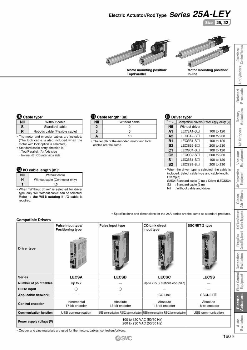
Electric Actuator/Rod Type
25A-LEY 16 100B C 11 6N
* Refer to the applicable stroke table.
* When “With lock/motor cover” is selected for the top mounting and right/left side parallel types, the motor body will stick out of the end of the body for size 16 with strokes 30 or less. Check for interference with workpieces before selecting a model.
* Refer to the operation manual for using the products. Please download it via our website, http://www.smcworld.com
Sq w e r t y u i o !0 !1 !2 !3
* Applicable stroke table
* Consult with SMC for non-standard strokes as they are produced as special orders.
q Size
r Lead [mm] t Stroke [mm]
y Motor option u Rod end thread
w Motor mounting position e Motor type
[CE-compliant products]q�EMC compliance was tested by
combining the electric actuator LEY series and the controller LEC series.The EMC depends on the configu-ration of the customer’s control panel and the relationship with other electrical equipment and wir-ing. Therefore conformity to the EMC directive cannot be certified for SMC components incorporated into the customer’s equipment un-der actual operating conditions. As a result it is necessary for the customer to verify conformity to the EMC directive for the machinery and equipment as a whole.
w�For the servo motor (24 VDC) specification, EMC compliance was tested by installing a noise filter set (LEC-NFA). Refer to the WEB catalog for the noise filter set. Refer to the LECA Operation Manual for installation.
[UL-compliant products]When conformity to UL is required, the electric actuator and controller/driver should be used with a UL1310 Class 2 power supply.
Caution
Standard
Symbol TypeSize Compatible
controllers/driverLEY16 LEY25 LEY32/40
Nil Step motor(Servo/24 VDC)
LECP6LECP1LECPA
LECPMJ
A Servo motor(24 VDC) — LECA6
Stroke[mm]
Model30 50 100 150 200 250 300 350 400 450 500
Manufacturablestroke range
[mm]
LEY16 — — — — 10 to 300
LEY25 — — 15 to 400
LEY32/40 20 to 500
30 30to to
500 500
Nil Female rod end
M Male rod end(1 rod end nut is included.)
C With motor cover
W With lock/motor cover
Symbol LEY16 LEY25 LEY32/40A 10 12 16
B 5 6 8
C 2.5 3 4
Nil Top mounting
R Right side parallel
L Left side parallel
D In-line
16253240
Solid state auto switches should be ordered separately.For details about auto switches, refer to page 164.
Applicable auto switchesD-M9N(V)-900, D-M9P(V)-900, D-M9B(V)-900D-M9NW(V)-900, D-M9PW(V)-900, D-M9BW(V)-900
Mounting Bracket Part No. for Series 25A-
*1 When ordering foot brackets, order 2 pieces per actuator.*2 Parts belonging to each bracket are as follows.
Foot, Flange: Body mounting bolt, Double clevis: Clevis pin, Type C retaining ring for axis, Body mounting bolt
Applicable size Foot *1 Flange Double clevis
16 25-LEY-L016 25-LEY-F016 25-LEY-D016
25 25-LEY-L025 25-LEY-F025 25-LEY-D025
32, 40 25-LEY-L032 25-LEY-F032 25-LEY-D032
Surface treatment RAYDENT® RAYDENT® Coating
(Size 16: Electroless nickel plating)
Step Motor (Servo/24 VDC) Servo Motor (24 VDC)
RoHS
q w
®
25A-P-B-P157-web-CS3e.indd 157 15.2.13 2:06:16 PM

Compatible Controllers/Driver
Type
Step data input type
Step data input type
CC-Link direct input type
Programless type Pulse input type
Series LECP6 LECA6 LECPMJ LECP1 LECPA
FeaturesValue (Step data) input
Standard controllerCC-Link direct input
Capable of setting up operation(step data) without using a
PC or teaching box
Operation bypulse signals
Compatible motorStep motor
(Servo/24 VDC)Servo motor
(24 VDC)Step motor
(Servo/24 VDC)
Maximum number of step data 64 points 64 points 14 points —
Power supply voltage 24 VDC
* Copper and zinc materials are used for the motors, cables, controllers/drivers.
* Specifications and dimensions for the 25A-series are the same as standard products.
158
Electric Actuator/Rod Type Series 25A-LEY
NilD
Screw mountingDIN rail mounting*1
* Produced upon receipt of order (Robotic cable only)*1 Mounting bracket is shipped together, (but not assembled).
*2 For horizontal cantilever mounting with the rod flange, head flange and ends tapped, use the actuator within the following stroke range. · LEY25: 200 or less · LEY32/40: 100 or less
*3 For mounting with the double clevis, use the actuator within the following stroke range. · LEY16: 100 or less · LEY25: 200 or less · LEY32/40: 200 or less
*4 Head f lange is not avai lab le for the LEY32/40.
*1 For details about controllers/driver and compatible motors, refer to the compatible controllers/driver below.
*2 Only available for the motor type “Step motor”.
*3 Not applicable to CE.*4 When pulse signals are open collector, order
the current limit resistor (LEC-PA-R-) separately.
*1 DIN rail is not included. Order it separately.
i Mounting*1 o Actuator cable type*1 !0 Actuator cable length [m]
!1 Controller/Driver type*1 !2 I/O cable length [m]*1, Communication plug
!3 Controller/Driver mounting
Motor mounting position: Top/Parallel
*1 The standard cable should be used on fixed parts. For using on moving parts, select the robotic cable.
*2 Only available for the motor type “Step motor”.
*1 When “Without controller/driver” is selected for controller/driver types, I/O cable cannot be selected. Refer to the catalog CAT. E102 if I/O cable is required.
*2 When “Pulse input type” is selected for controller/driver types, pulse input usable only with differential. Only 1.5 m cables usable with open collector.
*3 When “CC-Link direct input type” is selected for controller/driver types, I/O cable is not included. Only “Nil”, “S” or “T” can be selected.
Motor mounting position: In-line
Nil Without controller/driver
6N LECP6/LECA6(Step data input type)
NPN
6P PNP
1N LECP1*2
(Programless type)NPN
1P PNP
MJ LECPMJ*2 *3
(CC-Link direct input type)—
AN LECPA*2 *4
(Pulse input type)NPN
AP PNP
Symbol TypeMotor mounting positionTop/Parallel In-line
Nil Ends tapped (Standard)*2 U Body bottom tapped L Foot —
F Rod flange*2 G Head flange*2 *4 —
D Double clevis*3 —
Nil Without cable
S Standard cable*2
R Robotic cable (Flexible cable)
Nil Without cable
1 1.5
3 3
5 5
8 8*
A 10*
B 15*
C 20*
Nil Without cable (Without communication plug connector*3)
1 1.5
3 3*2
5 5*2
S Straight type communication plug connector*3
T T-branch type communication plug connector*3
25A-P-B-P158-web修正-CS3e.indd 158 14.9.11 5:55:39 PM
Air C
ylin
ders
Air
Grip
pers
Dire
ctio
nal
Cont
rol V
alve
sR
elat
edP
rod
uct
sR
ota
ryA
ctu
ato
rsV
acuu
mE
quip
men
tAi
r Pre
para
tion
Equi
pmen
tAir
Filte
rs/Pre
ssure
Contr
ol Eq
uipme
ntFit
tings
/Flow
Contr
ol Eq
uipme
ntD
etec
tio
nS
wit
ches
Flui
d Co
ntro
lEq
uipm
ent
Ele
ctri
cA
ctu
ato
rsA
uto
Sw
itch
esC
lean
Air
Filt
ers
A

Series compatible withsecondary batteries
RoHS
AC Servo Motor
How to Order
159
Motor
LEY25, 32
* Applicable stroke table
* Consult with SMC for non-standard strokes as they are produced as special orders.
w Size
* Refer to the table below for details.
y Stroke [mm]
* When “With lock” is selected for the top mounting and right/left side parallel types, the motor body will stick out of the end of the body for size 25 with strokes 30 or less. Check for interference with workpieces before selecting a model.
u Motor option
i Rod end thread
e Motor mounting position
*1 Mounting bracket is shipped together, (but not assembled).
*2 For horizontal cantilever mounting with the rod flange, head flange and ends tapped, use the actuator within the following stroke range. · LEY25: 200 or less · LEY32: 100 or less
*3 For mounting with the double clevis, use the actuator within the following stroke range. · LEY25: 200 or less · LEY32: 200 or less
*4 Rod flange is not available for the LEY25 with stroke 30 and motor option “With lock”.
*5 Head flange is not available for the LEY32.
* The values shown in ( ) are the lead for size 32 top mounting, right/left side parallel types. (Equivalent lead which includes the pulley ratio [1.25:1])
t Lead [mm]
Electric Actuator/Rod Type
25, 32Size
o Mounting*1
r Motor type*1
*1 For motor type “S2” and “S6”, the compatible driver part number suffixes are “S1” and “S5” respectively.
*2 For details about the driver, refer to the WEB catalog.
Standard
Symbol Type Output [W] Actuator size Compatible drivers*2
S2 AC servo motor(Incremental encoder) 100 25 LECSA-S1
S3 AC servo motor(Incremental encoder) 200 32 LECSA-S3
S6 AC servo motor(Absolute encoder) 100 25
LECSB-S5LECSC-S5LECSS-S5
S7 AC servo motor(Absolute encoder) 200 32
LECSB-S7LECSC-S7LECSS-S7
Symbol TypeMotor mounting positionTop/Parallel In-line
Nil Ends tapped (Standard)*2 U Body bottom tapped L Foot —
F Rod flange*2 *4 G Head flange*2 *5 —
D Double clevis*3 —
Symbol LEY25 LEY32*
A 12 16 (20)
B 6 8 (10)
C 3 4 (5)
Nil Top mounting
R Right side parallel
L Left side parallel
D In-line
Nil Female rod end
M Male rod end(1 rod end nut is included.)
Nil Without option
B With lock*30 30
to to
500 500
Stroke[mm]Model 30 50 100 150 200 250 300 350 400 450 500 Manufacturable
stroke range [mm]
LEY25 — — 15 to 400
LEY32 20 to 500
2532
Solid state auto switches should be ordered separately.For details about auto switches, refer to page 164.
Applicable auto switchesD-M9N(V)-900, D-M9P(V)-900, D-M9B(V)-900D-M9NW(V)-900, D-M9PW(V)-900, D-M9BW(V)-900
Mounting Bracket Part No. for Series 25A-
*1 When ordering foot brackets, order 2 pieces per actuator.*2 Parts belonging to each bracket are as follows.
Foot, Flange: Body mounting bolt, Double clevis: Clevis pin, Type C retaining ring for axis, Body mounting bolt
Applicable size Foot*1 Flange Double clevis
25 25-LEY-L025 25-LEY-F025 25-LEY-D025
32 25-LEY-L032 25-LEY-F032 25-LEY-D032
Surface treatment RAYDENT® RAYDENT® Coating
(Size 16: Electroless nickel plating)
Series 25A-LEY
25A-LEY 25 100BH 2 A1Sw e r tq y u i o !0 !1 !2 !3
S2
q AccuracyNil Basic typeH High precision type
25A-P-B-P159-webA-CS3e.indd 159 15.2.13 2:05:19 PM
A
* Specifications and dimensions for the 25A-series are the same as standard products.
160
Electric Actuator/Rod Type Series 25A-LEY
Motor mounting position: Top/Parallel
Motor mounting position: In-line
* The motor and encoder cables are included. (The lock cable is also included when the motor with lock option is selected.)
* Standard cable entry direction is· Top/Parallel: (A) Axis side· In-line: (B) Counter axis side
!0 Cable type*
* The length of the encoder, motor and lock cables are the same.
!1 Cable length* [m]
Compatible Drivers
!2 Driver type*
* When the driver type is selected, the cable is included. Select cable type and cable length.Example)S2S2: Standard cable (2 m) + Driver (LECSS2)S2 : Standard cable (2 m)Nil : Without cable and driver
25, 32Size
Compatible drivers Power supply voltage (V)Nil Without driver —
A1 LECSA1-S 100 to 120
A2 LECSA2-S 200 to 230
B1 LECSB1-S 100 to 120
B2 LECSB2-S 200 to 230
C1 LECSC1-S 100 to 120
C2 LECSC2-S 200 to 230
S1 LECSS1-S 100 to 120
S2 LECSS2-S 200 to 230
Driver type
Pulse input type/Positioning type
Pulse input type CC-Link directinput type
SSCNET# type
Series LECSA LECSB LECSC LECSS
Number of point tables Up to 7 — Up to 255 (2 stations occupied) —
Pulse input — —
Applicable network — — CC-Link SSCNET3
Control encoder Incremental17-bit encoder
Absolute18-bit encoder
Absolute18-bit encoder
Absolute18-bit encoder
Communication function USB communication USB communication, RS422 communication USB communication, RS422 communication USB communication
Power supply voltage (V) 100 to 120 VAC (50/60 Hz)200 to 230 VAC (50/60 Hz)
* Copper and zinc materials are used for the motors, cables, controllers/drivers.
Nil Without cable
2 2
5 5
A 10
Nil Without cable
S Standard cable
R Robotic cable (Flexible cable)
!3 I/O cable length [m]*
Nil Without cable
H Without cable (Connector only)
1 1.5
* When “Without driver” is selected for driver type, only “Nil: Without cable” can be selected.Refer to the WEB catalog if I/O cable is required.
25A-P-B-P160-web修正-CS3e.indd 160 14.10.9 9:08:32 PM
Air C
ylin
ders
Air
Grip
pers
Dire
ctio
nal
Cont
rol V
alve
sR
elat
edP
rod
uct
sR
ota
ryA
ctu
ato
rsV
acuu
mE
quip
men
tAi
r Pre
para
tion
Equi
pmen
tAir
Filte
rs/Pre
ssure
Contr
ol Eq
uipme
ntFit
tings
/Flow
Contr
ol Eq
uipme
ntD
etec
tio
nS
wit
ches
Flui
d Co
ntro
lEq
uipm
ent
Ele
ctri
cA
ctu
ato
rsA
uto
Sw
itch
esC
lean
Air
Filt
ers
A