Embed Size (px)
Citation preview

ELEC 2200-002Digital Logic Circuits
Fall 2015Switching Algebra (Chapter 2)
Vishwani D. AgrawalJames J. Danaher Professor
Department of Electrical and Computer EngineeringAuburn University, Auburn, AL 36849http://www.eng.auburn.edu/~vagrawal
Fall 2015, Sep 30 . . . ELEC2200-002 Lecture 4 1
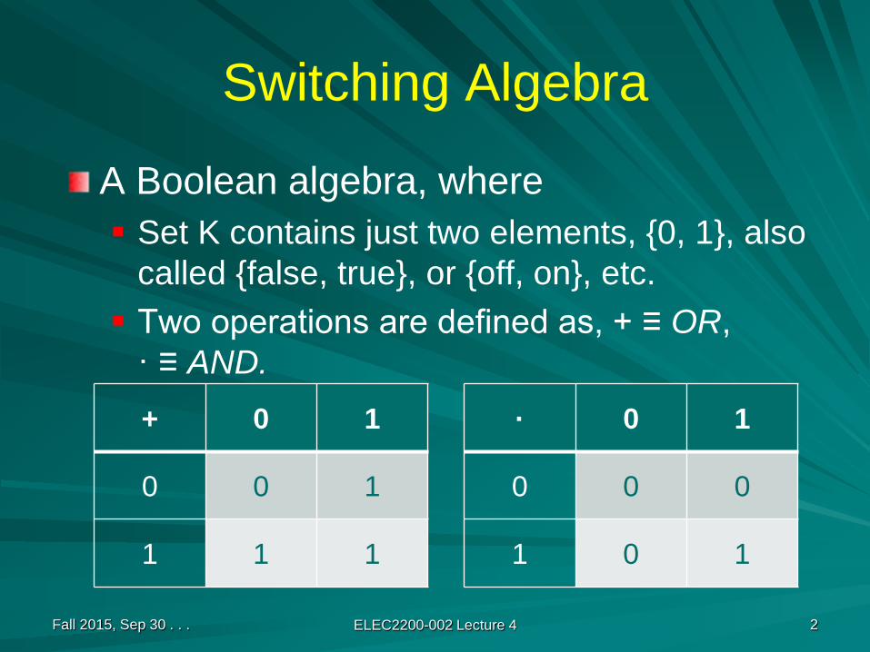
Switching Algebra
A Boolean algebra, where Set K contains just two elements, {0, 1}, also
called {false, true}, or {off, on}, etc. Two operations are defined as, + ≡ OR,
· ≡ AND.
Fall 2015, Sep 30 . . . ELEC2200-002 Lecture 4 2
+ 0 1
0 0 1
1 1 1
· 0 1
0 0 0
1 0 1
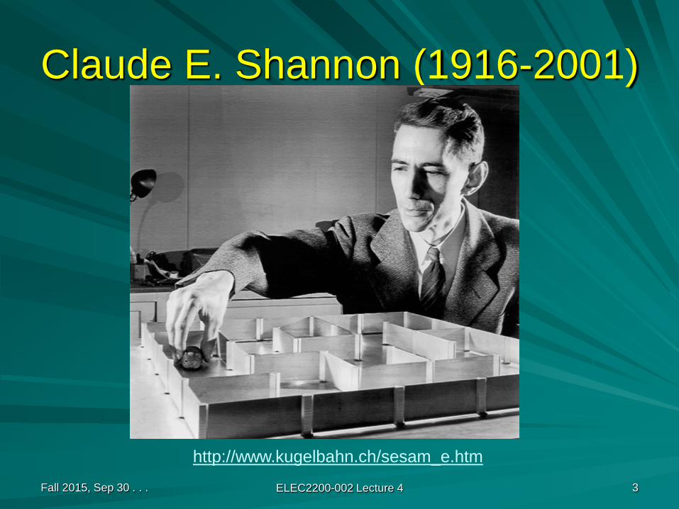
Claude E. Shannon (1916-2001)
Fall 2015, Sep 30 . . . ELEC2200-002 Lecture 4 3
http://www.kugelbahn.ch/sesam_e.htm

Shannon’s Legacy
A Symbolic Analysis of Relay and Switching Circuits, Master’s Thesis, MIT, 1940. Perhaps the most influential master’s thesis of the 20th
century.An Algebra for Theoretical Genetics, PhD Thesis, MIT, 1940.Founded the field of Information Theory.C. E. Shannon and W. Weaver, The Mathematical Theory of Communication, University of Illinois Press, 1949. A “must read.”
Fall 2015, Sep 30 . . . ELEC2200-002 Lecture 4 4

Switching Devices
Electromechanical relays (1940s)Vacuum tubes (1950s)Bipolar transistors (1960 - 1980)Field effect transistors (1980 - )Integrated circuits (1970 - )Nanotechnology devices (future)
Fall 2015, Sep 30 . . . ELEC2200-002 Lecture 4 5
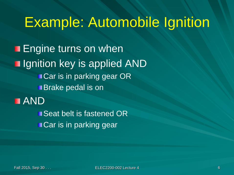
Example: Automobile Ignition
Engine turns on whenIgnition key is applied AND
Car is in parking gear ORBrake pedal is on
ANDSeat belt is fastened ORCar is in parking gear
Fall 2015, Sep 30 . . . ELEC2200-002 Lecture 4 6

Switching logic
Fall 2015, Sep 30 . . . ELEC2200-002 Lecture 4 7
Battery
Key
Parking gear
Brake pedal Parking gear
Seat belt
Motor
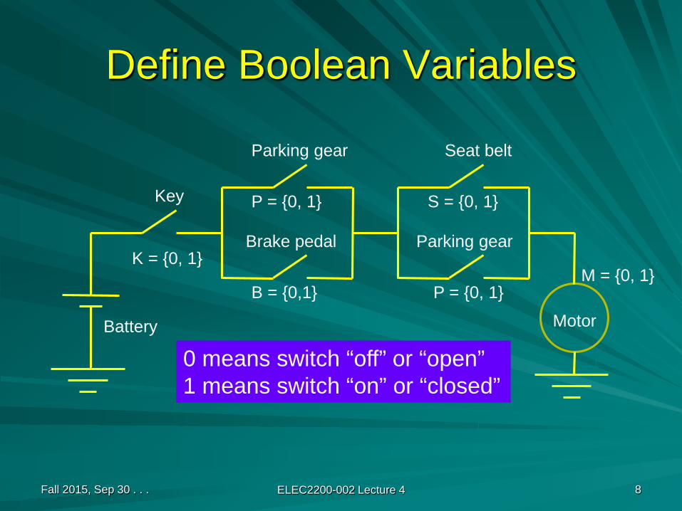
Define Boolean Variables
Fall 2015, Sep 30 . . . ELEC2200-002 Lecture 4 8
Battery
Key
Parking gear
Brake pedal Parking gear
Seat belt
Motor
K = {0, 1}
P = {0, 1}
B = {0,1} P = {0, 1}
S = {0, 1}
0 means switch “off” or “open”1 means switch “on” or “closed”
M = {0, 1}
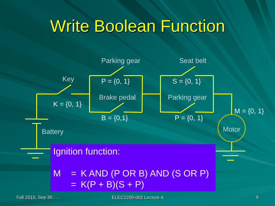
Write Boolean Function
Fall 2015, Sep 30 . . . ELEC2200-002 Lecture 4 9
Battery
Key
Parking gear
Brake pedal Parking gear
Seat belt
Motor
K = {0, 1}
P = {0, 1}
B = {0,1} P = {0, 1}
S = {0, 1}
Ignition function:
M = K AND (P OR B) AND (S OR P)= K(P + B)(S + P)
M = {0, 1}

Simplify Boolean Function
Fall 2015, Sep 30 . . . ELEC2200-002 Lecture 4 10
M = K AND (P OR B) AND (S OR P)
= K(P + B)(S + P)
= K(P + B)(P + S) Commutativity
= K (P + B S) Distributivity
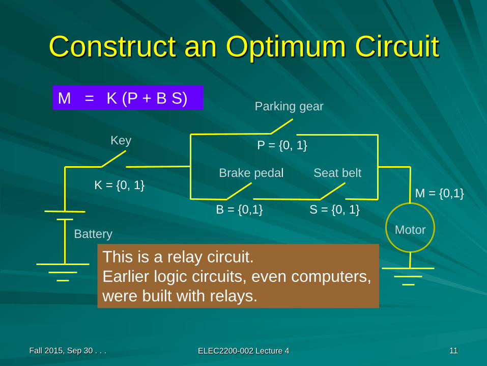
Construct an Optimum Circuit
Fall 2015, Sep 30 . . . ELEC2200-002 Lecture 4 11
Battery
Key
Parking gear
Brake pedal Seat belt
Motor
K = {0, 1}
P = {0, 1}
B = {0,1} S = {0, 1}
M = K (P + B S)
M = {0,1}
This is a relay circuit.Earlier logic circuits, even computers,were built with relays.
Implementing with Relays
An electromechanical relay contains:ElectromagnetCurrent sourceA switch, spring-loaded, normally open or closed
Switch has two states, open (0) or closed (1).The state of switch is controlled by “not applying” or “applying” current to electromagnet.
Fall 2015, Sep 30 . . . ELEC2200-002 Lecture 4 12

One Switch Controlling Other
Switches X and Y are normally open.Y cannot close unless a current is applied to X.
Fall 2015, Sep 30 . . . ELEC2200-002 Lecture 4 13
XY
Y = X
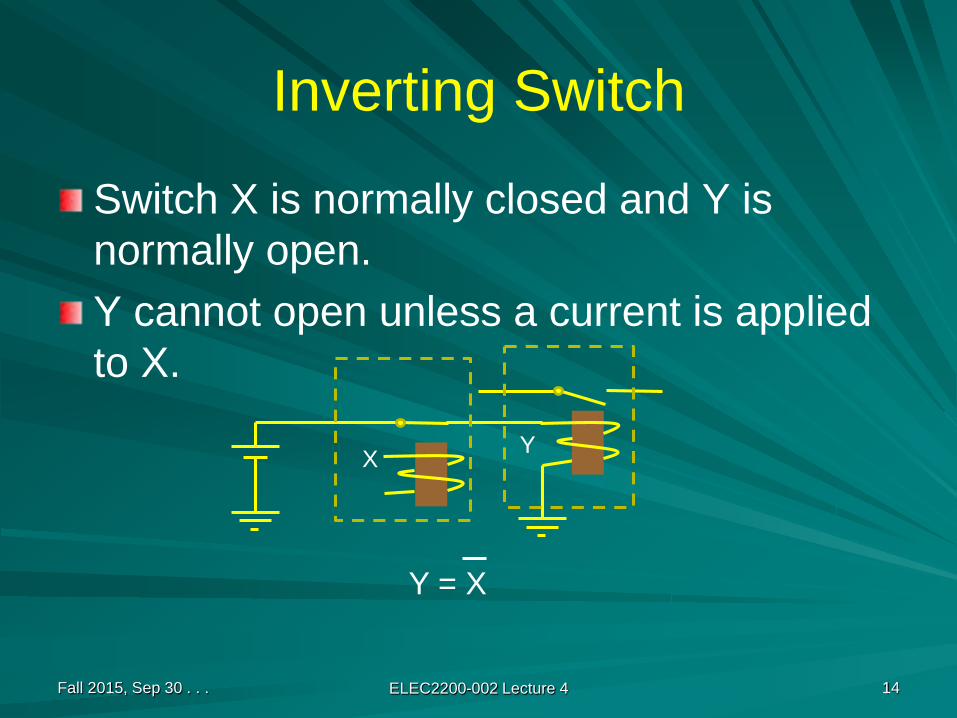
Inverting Switch
Switch X is normally closed and Y is normally open.Y cannot open unless a current is applied to X.
Fall 2015, Sep 30 . . . ELEC2200-002 Lecture 4 14
X Y
Y = X
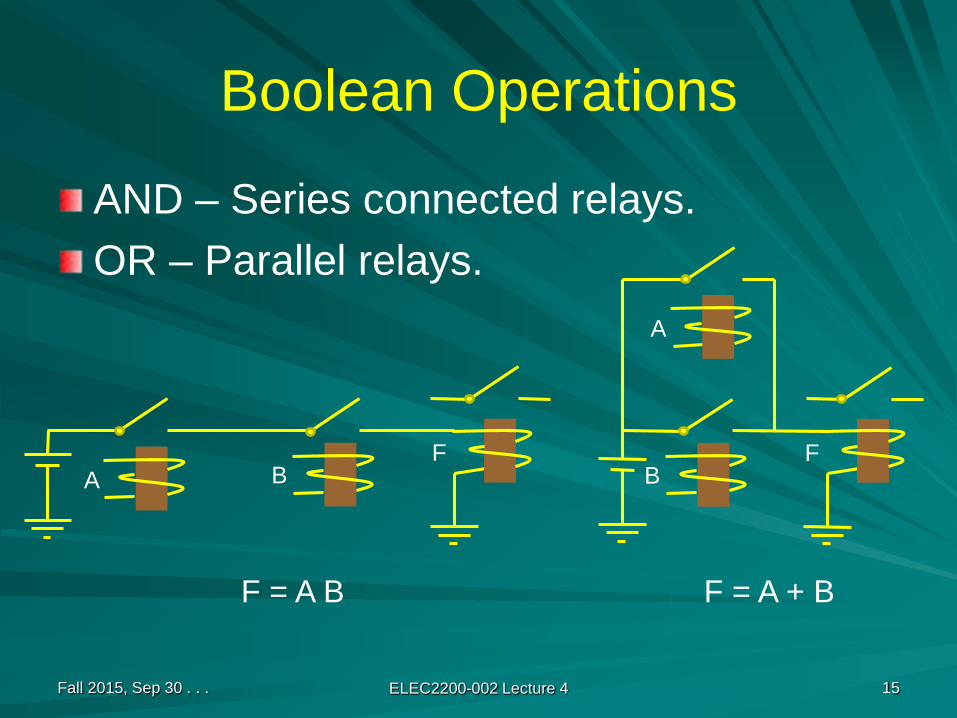
Boolean Operations
AND – Series connected relays.OR – Parallel relays.
Fall 2015, Sep 30 . . . ELEC2200-002 Lecture 4 15
A BF
F = A B
BF
A
F = A + B

Complement (Inversion)
Fall 2015, Sep 30 . . . ELEC2200-002 Lecture 4 16
AF
F = A
BF
A
F = A + B
= A · B

Relay ComputersConrad Zuse (1910-1995)
Fall 2015, Sep 30 . . . ELEC2200-002 Lecture 4 17
Z1 (1938)
Z3 (1941)

Electronic Switching Devices
Fall 2015, Sep 30 . . . ELEC2200-002 Lecture 4 18
Electron TubeFleming, 1904
de Forest, 1906
Point Contact TransistorBardeen, Brattain, Shockley, 1948
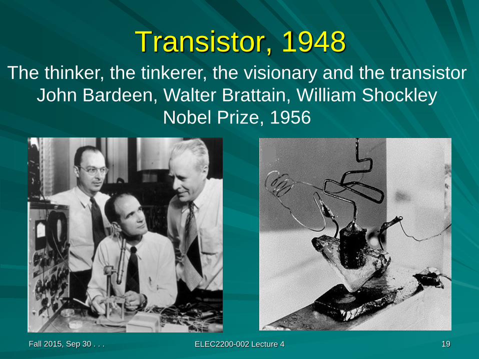
Transistor, 1948
Fall 2015, Sep 30 . . . ELEC2200-002 Lecture 4 19
The thinker, the tinkerer, the visionary and the transistorJohn Bardeen, Walter Brattain, William Shockley
Nobel Prize, 1956

Bell Laboratories, Murray Hill, New Jersey
Fall 2015, Sep 30 . . . ELEC2200-002 Lecture 4 20

Fall 2015, Sep 30 . . . ELEC2200-002 Lecture 4 21
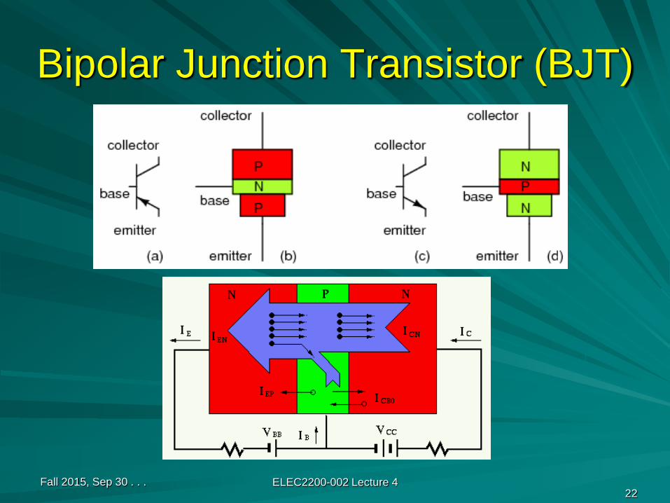
Bipolar Junction Transistor (BJT)
Fall 2015, Sep 30 . . . ELEC2200-002 Lecture 422

Field Effect Transistor (FET)
Fall 2015, Sep 30 . . . ELEC2200-002 Lecture 4 23
a.k.a.metal oxidesemiconductor(MOS) FET.
(metaloxide)
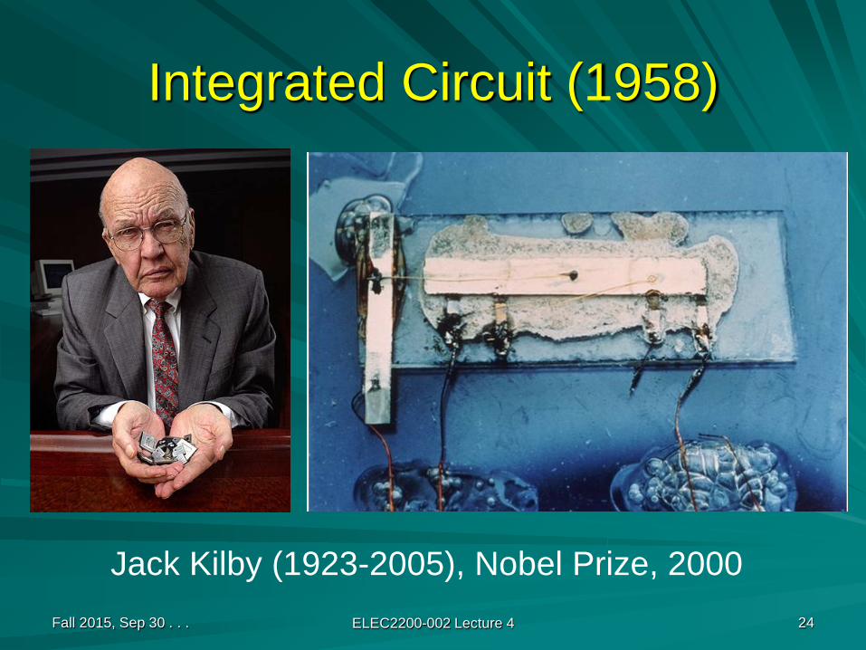
Integrated Circuit (1958)
Fall 2015, Sep 30 . . . ELEC2200-002 Lecture 4 24
Jack Kilby (1923-2005), Nobel Prize, 2000
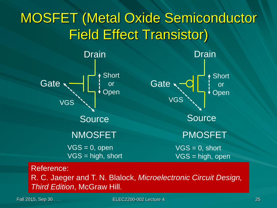
MOSFET (Metal Oxide Semiconductor Field Effect Transistor)
Fall 2015, Sep 30 . . . ELEC2200-002 Lecture 4 25
Gate
Drain
Source
Gate
Drain
Source
NMOSFET PMOSFET
Shortor
Open
Shortor
OpenVGS VGS
VGS = 0, openVGS = high, short
VGS = 0, shortVGS = high, open
Reference:R. C. Jaeger and T. N. Blalock, Microelectronic Circuit Design, Third Edition, McGraw Hill.
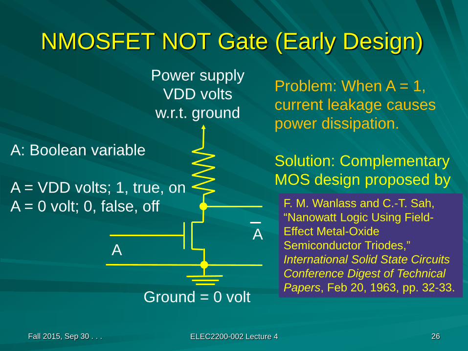
NMOSFET NOT Gate (Early Design)
Fall 2015, Sep 30 . . . ELEC2200-002 Lecture 4 26
Ground = 0 volt
Power supplyVDD volts
w.r.t. ground
AA
Problem: When A = 1,current leakage causespower dissipation.
Solution: ComplementaryMOS design proposed by
F. M. Wanlass and C.-T. Sah, “Nanowatt Logic Using Field-Effect Metal-Oxide Semiconductor Triodes,” International Solid State Circuits Conference Digest of Technical Papers, Feb 20, 1963, pp. 32-33.
A: Boolean variable
A = VDD volts; 1, true, onA = 0 volt; 0, false, off
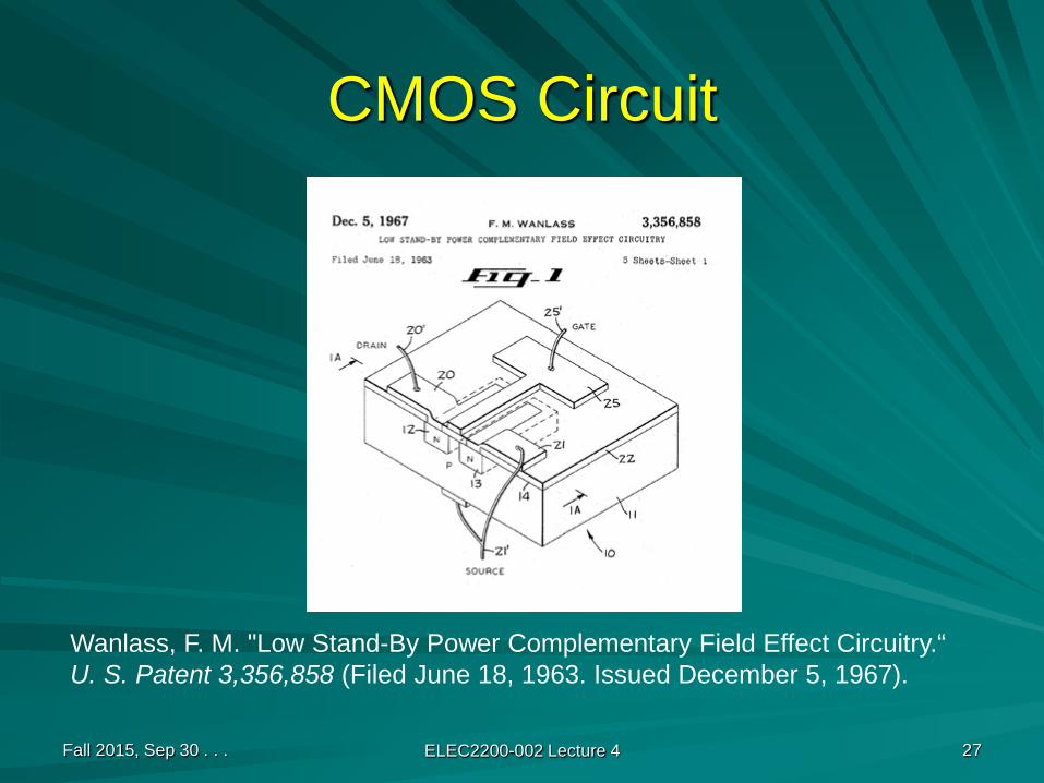
CMOS Circuit
Fall 2015, Sep 30 . . . ELEC2200-002 Lecture 4 27
Wanlass, F. M. "Low Stand-By Power Complementary Field Effect Circuitry.“U. S. Patent 3,356,858 (Filed June 18, 1963. Issued December 5, 1967).

CMOS NOT Gate (Modern Design)
Fall 2015, Sep 30 . . . ELEC2200-002 Lecture 4 28
VDD = 1 volt; voltage depends on technology.
Ground
A A
A = VDD = 1 volt is state “1”A = GND = 0 volt is state “0”
Power supply
GND
Truth Table
A A
0 1
1 0
A A
ElectricalCircuit
Symbol
Boolean Function
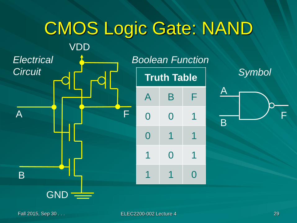
CMOS Logic Gate: NAND
Fall 2015, Sep 30 . . . ELEC2200-002 Lecture 4 29
VDD
A F
GND
Truth Table
A B F
0 0 1
0 1 1
1 0 1
1 1 0
A
B
B
F
ElectricalCircuit
Boolean FunctionSymbol

CMOS Logic Gate: NOR
Fall 2015, Sep 30 . . . ELEC2200-002 Lecture 4 30
VDD
A
F
GND
Truth Table
A B F
0 0 1
0 1 0
1 0 0
1 1 0
A
B
B
F
ElectricalCircuit
Boolean FunctionSymbol
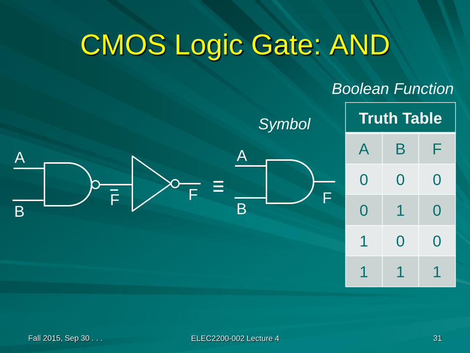
CMOS Logic Gate: AND
Fall 2015, Sep 30 . . . ELEC2200-002 Lecture 4 31
Truth Table
A B F
0 0 0
0 1 0
1 0 0
1 1 1
A
BF
Boolean Function
Symbol
A
BFF ≡

CMOS Logic Gate: OR
Fall 2015, Sep 30 . . . ELEC2200-002 Lecture 4 32
Truth Table
A B F
0 0 0
0 1 1
1 0 1
1 1 1
F
Boolean Function
Symbol
FF ≡A
B
A
B

CMOS Gates
Logic functionNumber of transistors
1 or 2 inputs N inputs
NOT 2 -
AND 6 2N + 2
OR 6 2N + 2
NAND 4 2N
NOR 4 2N
Fall 2015, Sep 30 . . . ELEC2200-002 Lecture 4 33

Optimized Ignition Logic
Fall 2015, Sep 30 . . . ELEC2200-002 Lecture 4 34
M = K (P + B S)= KP + KBS
K
P
KP
SB
KBS
M
3 gates, 20 transistors. Can we reduce transistors?

Further Optimization
Fall 2015, Sep 30 . . . ELEC2200-002 Lecture 4 35
M = K (P + B S) = KP + KBS (Distr. law)
= KP + KBS (Theorem 3, involution)
= KP · KBS (De Morgan’s theorem)
K
PKP
SB
KBS
M
3 gates, 14 transistors.
NAND gates4+6 transistors

Digital Systems
Fall 2015, Sep 30 . . . ELEC2200-002 Lecture 4 36
DIGITALCIRCUITS

Digital Logic Design
Representation of switching function:Truth tableCanonical formsKarnaugh map
Logic minimization: Minimize number of literals.Technology mapping: Implement logic function using predesigned gates or building blocks from a technology library.
Fall 2015, Sep 30 . . . ELEC2200-002 Lecture 4 37
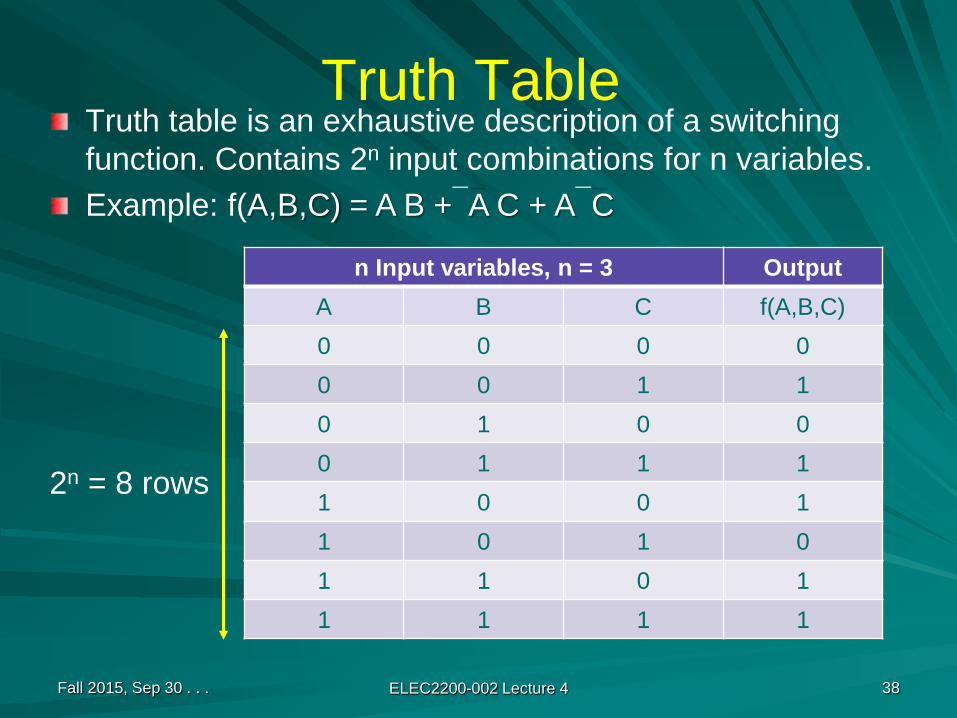
Truth TableTruth table is an exhaustive description of a switching function. Contains 2n input combinations for n variables.Example: f(A,B,C) = A B +A C + AC
Fall 2015, Sep 30 . . . ELEC2200-002 Lecture 4 38
n Input variables, n = 3 OutputA B C f(A,B,C)0 0 0 00 0 1 10 1 0 00 1 1 11 0 0 11 0 1 01 1 0 11 1 1 1
2n = 8 rows
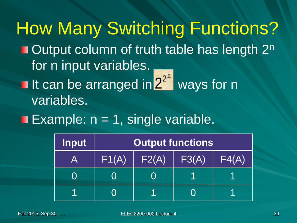
How Many Switching Functions?Output column of truth table has length 2n
for n input variables.It can be arranged in ways for n variables.Example: n = 1, single variable.
Fall 2015, Sep 30 . . . ELEC2200-002 Lecture 4 39
n22
Input Output functionsA F1(A) F2(A) F3(A) F4(A)
0 0 0 1 1
1 0 1 0 1

DefinitionsBoolean variable: A variable denoted by a symbol; can assume a value 0 or 1.Literal: Symbol for a variable or its complement.Product or product term: A set of literals, ANDed together. Example, a bc.Cube: Same as a product term.Sum: A set of literals, Ored together. Example, a + b +c.
Fall 2015, Sep 30 . . . ELEC2200-002 Lecture 4 40

More DefinitionsSOP (sum of products): A Boolean function expressed as a sum of products.Example: f(A,B,C) = A B +A C + ACPOS (product of sums): A Boolean function expressed as a product of sums.Example:f(A,B,C) = (A +B +C) (A + B +C) ( A +B + C)
Fall 2015, Sep 30 . . . ELEC2200-002 Lecture 4 41
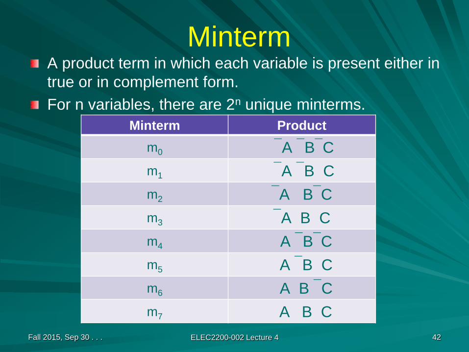
MintermA product term in which each variable is present either in true or in complement form.For n variables, there are 2n unique minterms.
Fall 2015, Sep 30 . . . ELEC2200-002 Lecture 4 42
Minterm Productm0 A BCm1 A B Cm2 A BCm3 A B Cm4 A BCm5 A B Cm6 A B Cm7 A B C
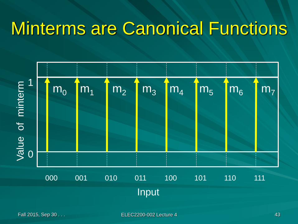
Minterms are Canonical Functions
Fall 2015, Sep 30 . . . ELEC2200-002 Lecture 4 43
000 001 010 011 100 101 110 111
Input
Valu
e o
f m
inte
rm
1
0
m0 m1 m2 m3 m4 m5 m6 m7
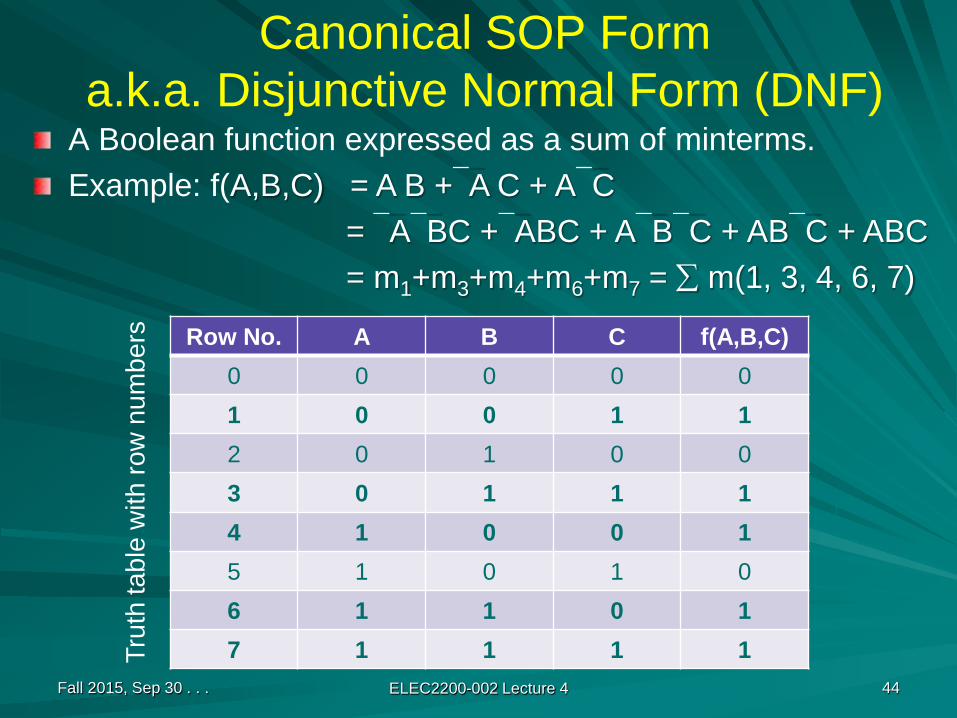
Canonical SOP Forma.k.a. Disjunctive Normal Form (DNF)
A Boolean function expressed as a sum of minterms.Example: f(A,B,C) = A B +A C + AC
= ABC +ABC + ABC + ABC + ABC= m1+m3+m4+m6+m7 = ∑ m(1, 3, 4, 6, 7)
Fall 2015, Sep 30 . . . ELEC2200-002 Lecture 4 44
Row No. A B C f(A,B,C)0 0 0 0 01 0 0 1 12 0 1 0 03 0 1 1 14 1 0 0 15 1 0 1 06 1 1 0 17 1 1 1 1Tr
uth
tabl
e w
ith ro
w n
umbe
rs

MaxtermA summation term in which each variable is present either in true or in complement form.For n variables, there are 2n unique maxterms.
Fall 2015, Sep 30 . . . ELEC2200-002 Lecture 4 45
Maxterm SumM0 A + B + CM1 A + B +CM2 A +B + CM3 A +B +CM4 A + B + C M5 A + B +C M6 A +B + C M7 A + B + C
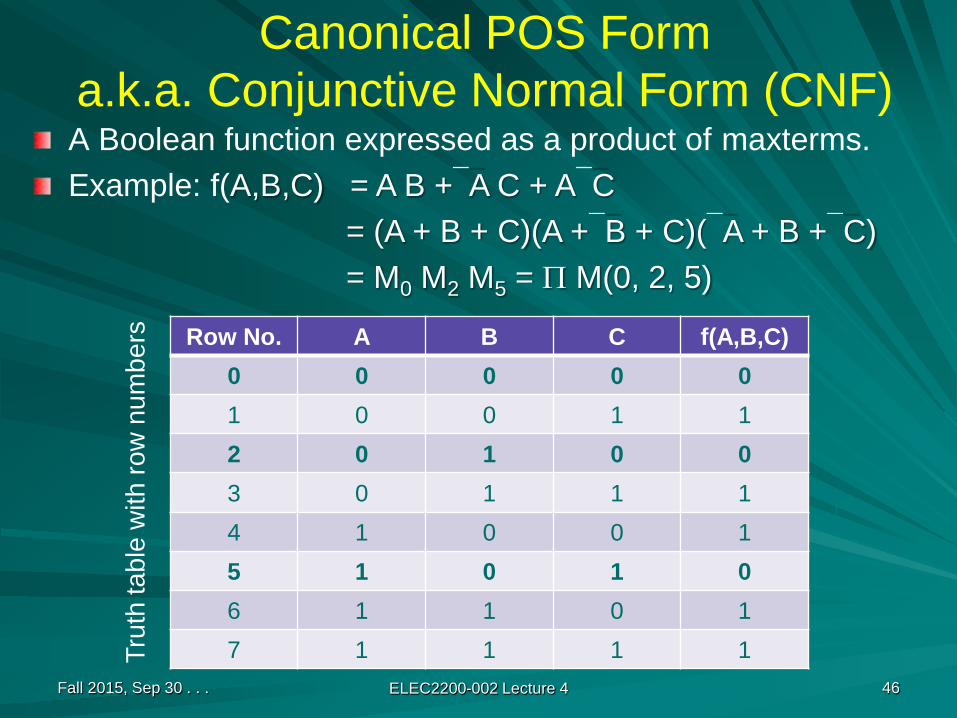
Canonical POS Forma.k.a. Conjunctive Normal Form (CNF)A Boolean function expressed as a product of maxterms.Example: f(A,B,C) = A B +A C + AC
= (A + B + C)(A +B + C)(A + B +C)= M0 M2 M5 = Π M(0, 2, 5)
Fall 2015, Sep 30 . . . ELEC2200-002 Lecture 4 46
Row No. A B C f(A,B,C)0 0 0 0 01 0 0 1 12 0 1 0 03 0 1 1 14 1 0 0 15 1 0 1 06 1 1 0 17 1 1 1 1Tr
uth
tabl
e w
ith ro
w n
umbe
rs
Canonical Forms are UniqueA canonical form completely defines a Boolean function. That is, for every input the canonical form specifies the value of the function.To determine canonical form:
Construct truth table and sum minterms corresponding to 1 outputs, or multiply maxterms corresponding to 0 outputs.Alternatively, use Shannon’s expansion theorem (see Section 2.2.3, page 101).
Two Boolean functions are identical if and only if their canonical forms are identical.
Fall 2015, Sep 30 . . . ELEC2200-002 Lecture 4 47
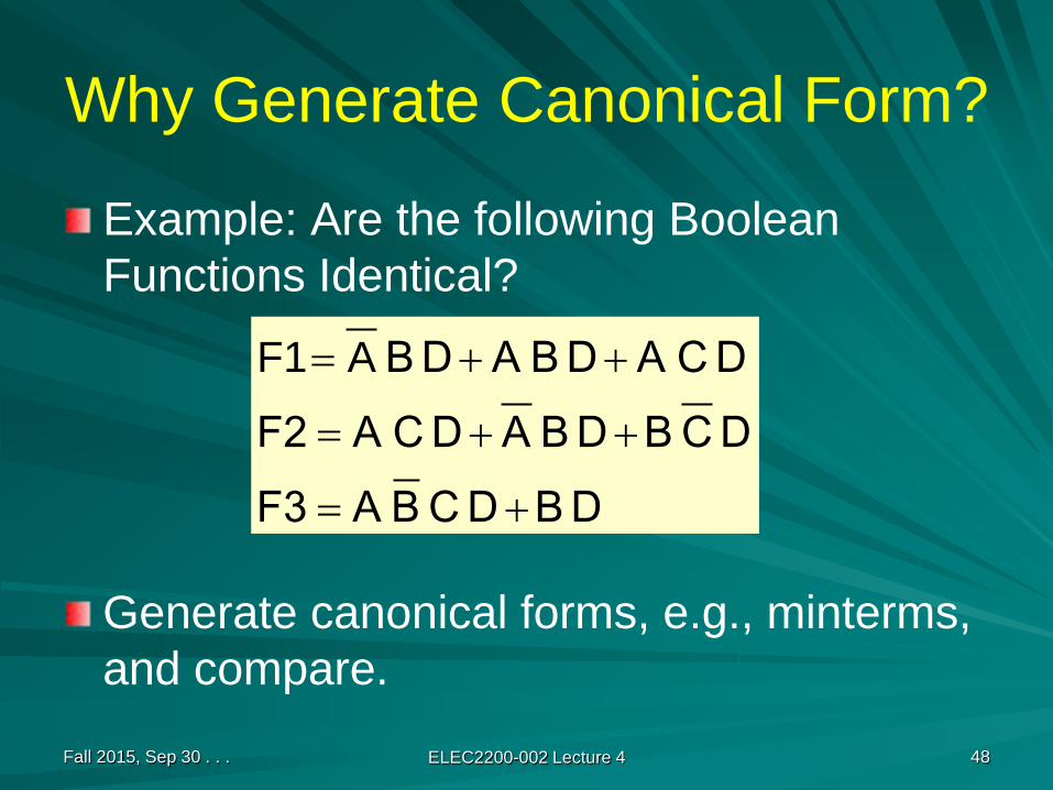
Why Generate Canonical Form?
Example: Are the following Boolean Functions Identical?
Generate canonical forms, e.g., minterms, and compare.
Fall 2015, Sep 30 . . . ELEC2200-002 Lecture 4 48
D BD C B AF3D C BD B AD C AF2D C AD B AD B
+=
++=
++= AF1
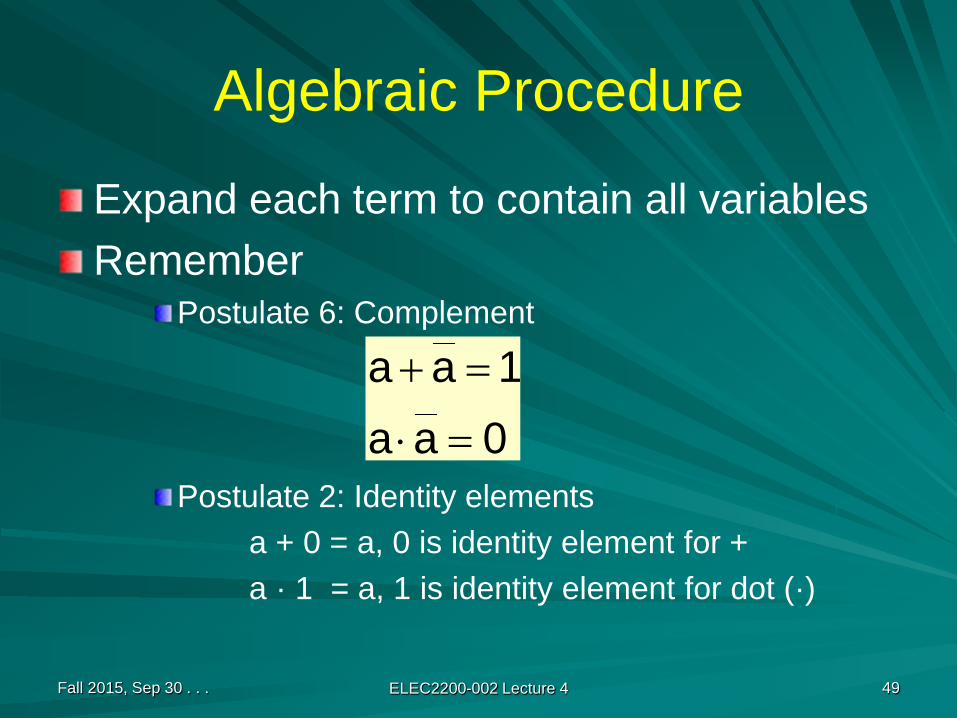
Algebraic Procedure
Expand each term to contain all variablesRemember
Postulate 6: Complement
Postulate 2: Identity elementsa + 0 = a, 0 is identity element for +a · 1 = a, 1 is identity element for dot (·)
Fall 2015, Sep 30 . . . ELEC2200-002 Lecture 4 49
0aa1aa
=⋅
=+
Fall 2015, Sep 30 . . . ELEC2200-002 Lecture 4 50
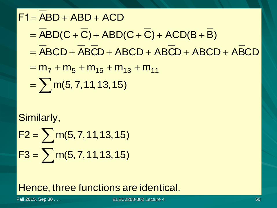
identical. are functions three ,Hence
)15 ,13 ,11 ,7 ,5(m3F
)15 ,13 ,11 ,7 ,5(mF2
Similarly,
)15 ,13 ,11 ,7 ,5(m
mmmmm CDBAABCDDCABABCDDCBABCD
)BB(ACD)CC(ABD)CC(BD
ACDABDBD
11131557
∑∑
∑
=
=
=
++++=+++++=
+++++=
++=
AAA F1

Karnaugh Map
1952: Edward M. Veitch invented a graphical procedure for digital circuit optimization.1953: Maurice Karnaugh perfected the map procedure:
“The Map Method for Synthesis of Combinational Logic Circuits,” Trans. AIEE, pt I, 72(9):593-599, November 1953.
Fall 2015, Sep 30 . . . ELEC2200-002 Lecture 4 51

Karnaugh Map: 2 Variables, A, B
Fall 2015, Sep 30 . . . ELEC2200-002 Lecture 4 52
A = 0 A = 1
B = 0
B = 1
m0
m1
m2
m3
m3 = AB = 11(numericalinterpretation)
00
01
10
11
UnitHammingdistancebetweenadjacent cells
Each cell isa minterm
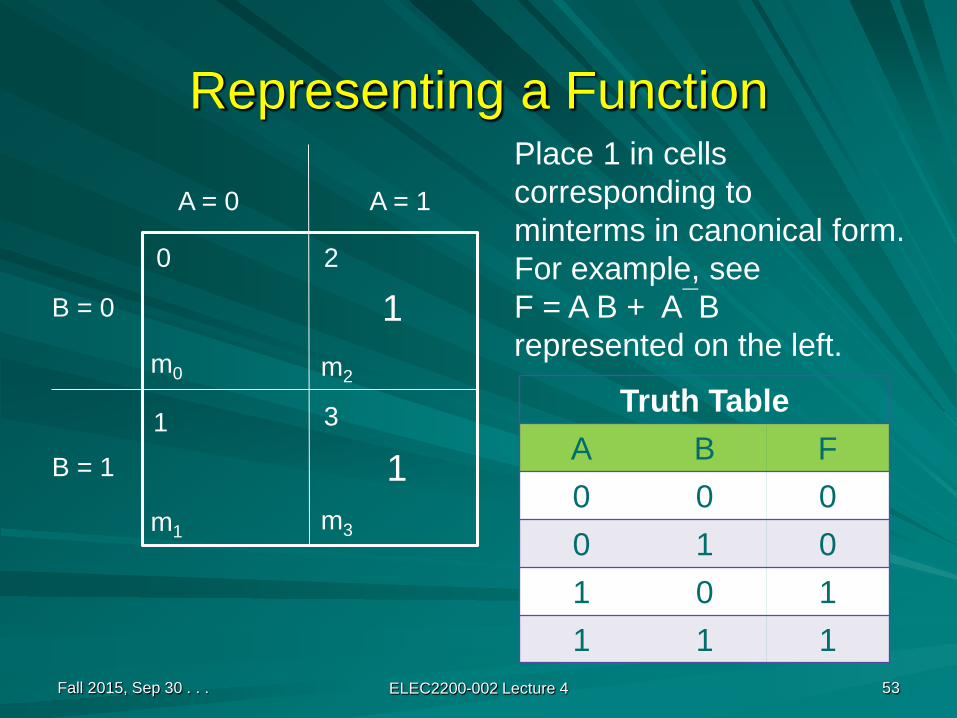
Representing a Function
Fall 2015, Sep 30 . . . ELEC2200-002 Lecture 4 53
A = 0 A = 1
B = 0
B = 1
m0
m1
m2
m3
0
1
2
3
Place 1 in cellscorresponding tominterms in canonical form.For example, see F = A B + ABrepresented on the left.
1
1
Truth TableA B F0 0 00 1 01 0 11 1 1
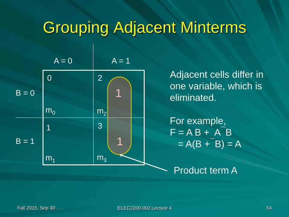
Grouping Adjacent Minterms
Fall 2015, Sep 30 . . . ELEC2200-002 Lecture 4 54
A = 0 A = 1
B = 0
B = 1
m0
m1
m2
m3
0
1
2
3
Adjacent cells differ inone variable, which iseliminated.
For example, F = A B + AB
= A(B +B) = A1
1
Product term A
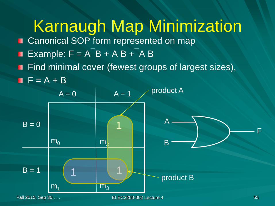
Karnaugh Map MinimizationCanonical SOP form represented on mapExample: F = AB + A B +A BFind minimal cover (fewest groups of largest sizes),F = A + B
Fall 2015, Sep 30 . . . ELEC2200-002 Lecture 4 55
A = 0 A = 1
B = 0
B = 1
m0
m1
m2
m3
1
11
product A
product B
A
BF
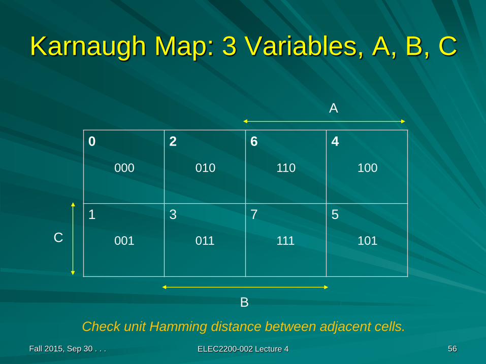
Karnaugh Map: 3 Variables, A, B, C
Fall 2015, Sep 30 . . . ELEC2200-002 Lecture 4 56
0 2 6 4
1 3 7 5
A
B
C
000
001
010
011
110
111
100
101
Check unit Hamming distance between adjacent cells.
Synthesizing a Digital FunctionStart with specification.Create a truth table from specification.Minimize (SOP with fewest literals):
Either write canonical SOPReduce using postulates and theoremsOr find largest cubes from Karnaugh map
Minimized SOP gives a two-level AND-OR circuit.NAND or NOR circuit for CMOS technology can be found using de Morgan’s theorem.
Fall 2015, Sep 30 . . . ELEC2200-002 Lecture 4 57

Example: Multiplexer
Inputs: A, B, COutput: FFunction:
F = A, when C = 1F = B, when C = 0
Fall 2015, Sep 30 . . . ELEC2200-002 Lecture 4 58
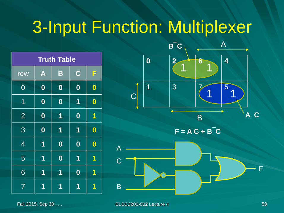
3-Input Function: Multiplexer
Truth Table
row A B C F
0 0 0 0 0
1 0 0 1 0
2 0 1 0 1
3 0 1 1 0
4 1 0 0 0
5 1 0 1 1
6 1 1 0 1
7 1 1 1 1
Fall 2015, Sep 30 . . . ELEC2200-002 Lecture 4 59
0 2 6 4
1 3 7 5
A
B
C
1
1
1
1
F = A C + BC
A C
BC
A
C
B
F
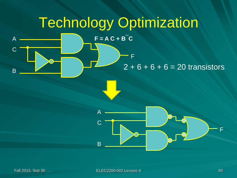
Technology Optimization
Fall 2015, Sep 30 . . . ELEC2200-002 Lecture 4 60
F = A C + BCA
C
B
F
A
C
B
F
2 + 6 + 6 + 6 = 20 transistors
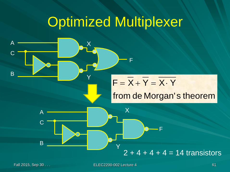
Optimized Multiplexer
Fall 2015, Sep 30 . . . ELEC2200-002 Lecture 4 61
A
C
B
F
X
Y
theorem sMorgan' de fromYXYXF ⋅=+=
A
C
B
F
X
Y2 + 4 + 4 + 4 = 14 transistors
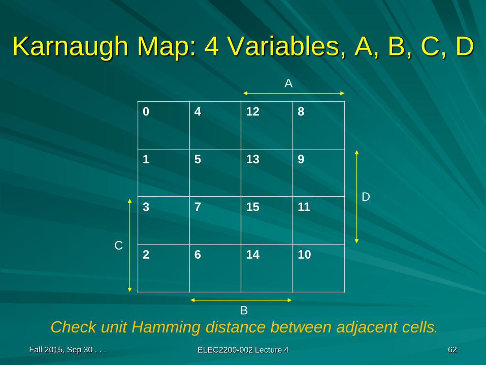
Karnaugh Map: 4 Variables, A, B, C, D
0 4 12 8
1 5 13 9
3 7 15 11
2 6 14 10
Fall 2015, Sep 30 . . . ELEC2200-002 Lecture 4 62
Check unit Hamming distance between adjacent cells.
A
B
D
C

Adjacency of Edge Cells
Fall 2015, Sep 30 . . . ELEC2200-002 Lecture 4 63
0
1
3
2
8
9
11
10
0 4 12 81014 6 2
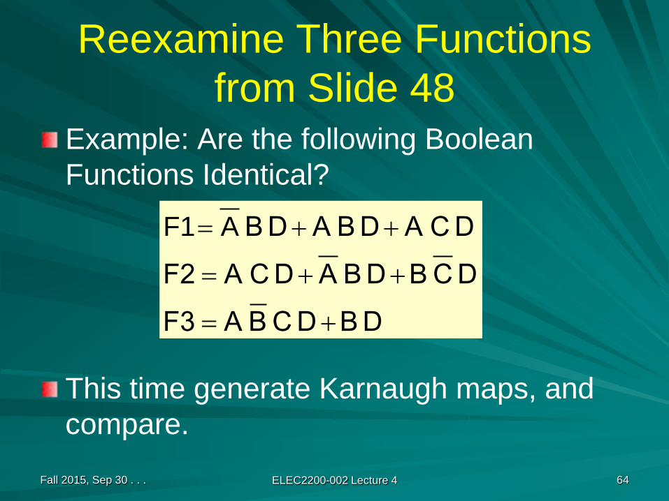
Reexamine Three Functions from Slide 48
Example: Are the following Boolean Functions Identical?
This time generate Karnaugh maps, and compare.
Fall 2015, Sep 30 . . . ELEC2200-002 Lecture 4 64
D BD C B AF3D C BD B AD C AF2D C AD B AD B
+=
++=
++= AF1

Karnaugh Map of F1
0 4 12 8
1 5 13 9
3 7 15 11
2 6 14 10
Fall 2015, Sep 30 . . . ELEC2200-002 Lecture 4 65
.
A
B
D
C
D C AD B AD B ++= AF1
F1 = Σm(5, 7, 11, 13, 15)
1 1
1 1 1
Karnaugh Map of F2
0 4 12 8
1 5 13 9
3 7 15 11
2 6 14 10
Fall 2015, Sep 30 . . . ELEC2200-002 Lecture 4 66
.
A
B
D
C
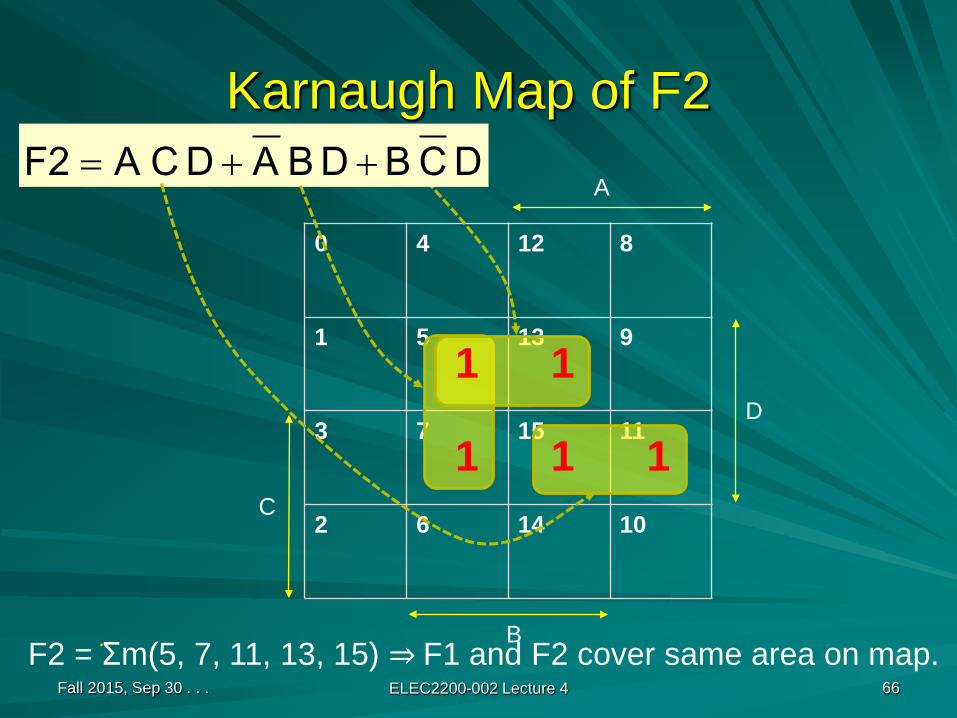
D C BD B AD C AF2 ++=
F2 = Σm(5, 7, 11, 13, 15) ⇒ F1 and F2 cover same area on map.
1 1
1 1 1
Karnaugh Map of F3
0 4 12 8
1 5 13 9
3 7 15 11
2 6 14 10
Fall 2015, Sep 30 . . . ELEC2200-002 Lecture 4 67
.
A
B
D
C
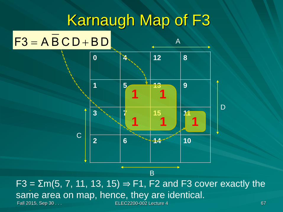
D BD C B AF3 +=
F3 = Σm(5, 7, 11, 13, 15) ⇒ F1, F2 and F3 cover exactly thesame area on map, hence, they are identical.
1 1
1 1 1
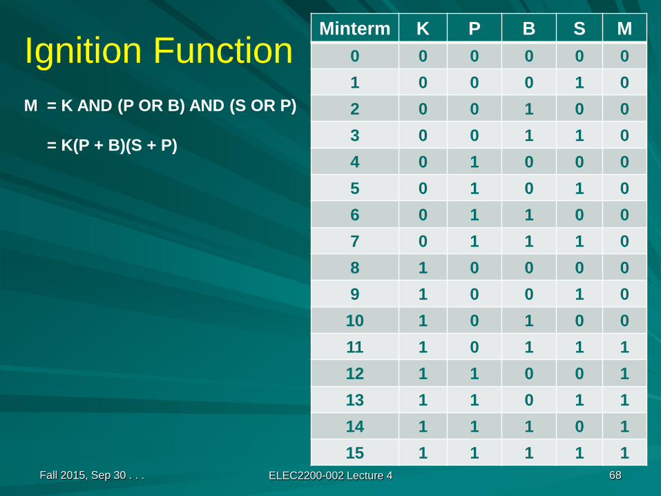
Ignition FunctionMinterm K P B S M
0 0 0 0 0 01 0 0 0 1 02 0 0 1 0 03 0 0 1 1 04 0 1 0 0 05 0 1 0 1 06 0 1 1 0 07 0 1 1 1 08 1 0 0 0 09 1 0 0 1 0
10 1 0 1 0 011 1 0 1 1 112 1 1 0 0 113 1 1 0 1 114 1 1 1 0 115 1 1 1 1 1
Fall 2015, Sep 30 . . . ELEC2200-002 Lecture 4 68
M = K AND (P OR B) AND (S OR P)
= K(P + B)(S + P)
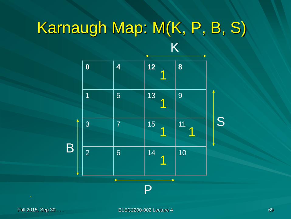
Karnaugh Map: M(K, P, B, S)
0 4 12 8
1 5 13 9
3 7 15 11
2 6 14 10
Fall 2015, Sep 30 . . . ELEC2200-002 Lecture 4 69
.
K
P
S
B
1
1
1 1
1
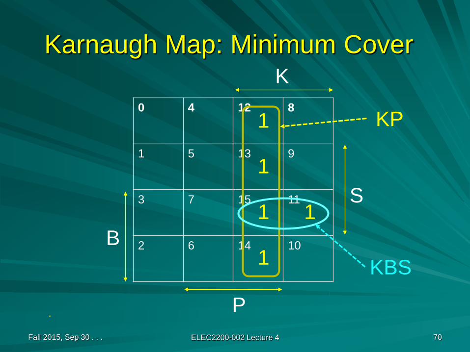
Karnaugh Map: Minimum Cover
0 4 12 8
1 5 13 9
3 7 15 11
2 6 14 10
Fall 2015, Sep 30 . . . ELEC2200-002 Lecture 4 70
.
K
P
S
B
1
1
1 1
1
KP
KBS
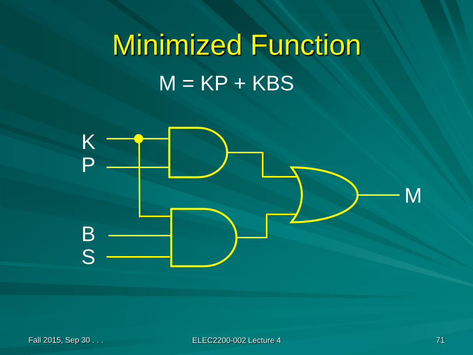
Minimized Function
Fall 2015, Sep 30 . . . ELEC2200-002 Lecture 4 71
M = KP + KBS
KP
BS
M
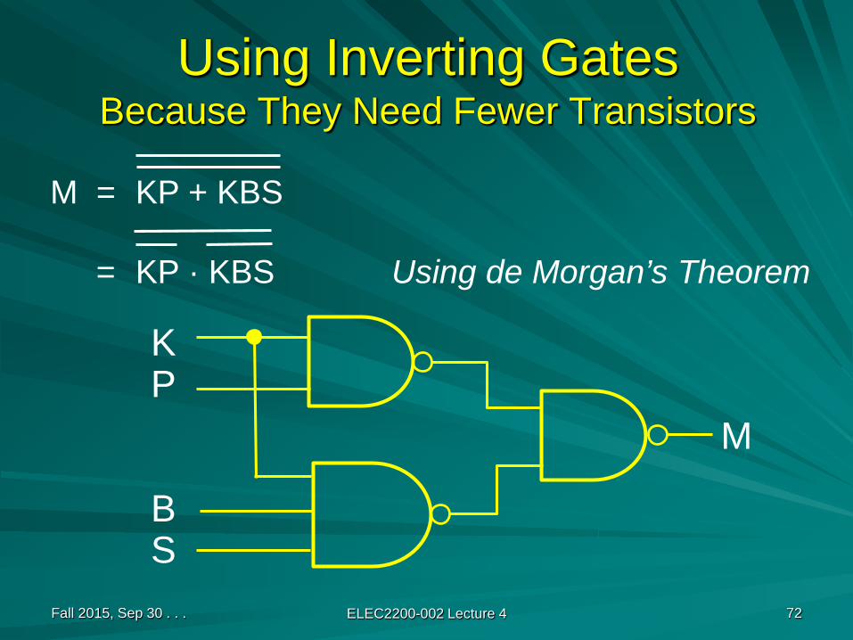
Using Inverting GatesBecause They Need Fewer Transistors
Fall 2015, Sep 30 . . . ELEC2200-002 Lecture 4 72
M = KP + KBS
= KP · KBS Using de Morgan’s Theorem
KP
BS
M

Karnaugh Map on the Web
Fall 2015, Sep 30 . . . ELEC2200-002 Lecture 4 73
http://www.ee.calpoly.edu/media/uploads/resources/KarnaughExplorer_1.html
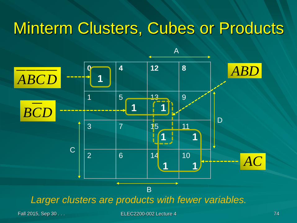
Minterm Clusters, Cubes or Products
01
4 12 8
1 51
131
9
3 7 151
111
2 6 141
101
Fall 2015, Sep 30 . . . ELEC2200-002 Lecture 4 74
Larger clusters are products with fewer variables.
A
B
D
C
DCBA
DCB
AC
ABD
Product
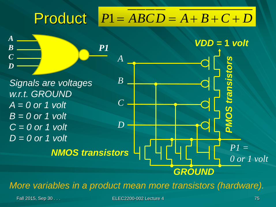
Fall 2015, Sep 30 . . . ELEC2200-002 Lecture 4 75
More variables in a product mean more transistors (hardware).
ABCD
DCBADCBAP +++==1
P1A
B
C
D
GROUND
VDD = 1 volt
PMO
S tr
ansi
stor
s
NMOS transistors
Signals are voltagesw.r.t. GROUNDA = 0 or 1 voltB = 0 or 1 voltC = 0 or 1 voltD = 0 or 1 volt
P1 =0 or 1 volt
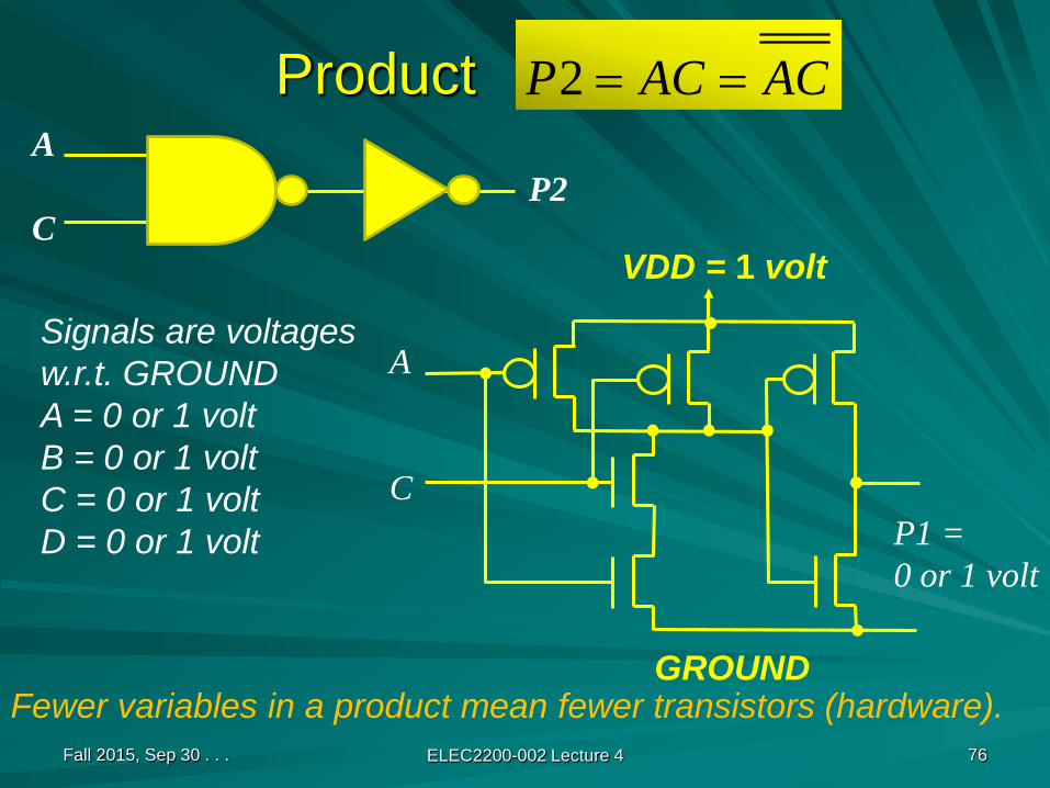
Product
Fall 2015, Sep 30 . . . ELEC2200-002 Lecture 4 76
Fewer variables in a product mean fewer transistors (hardware).
A
C
ACACP ==2
P2
A
C
GROUND
VDD = 1 volt
Signals are voltagesw.r.t. GROUNDA = 0 or 1 voltB = 0 or 1 voltC = 0 or 1 voltD = 0 or 1 volt P1 =
0 or 1 volt
ObservationsA larger minterm cluster is a product with fewer variables; requires fewer transistors.
Each gate input needs two transistors.
Smaller number of clusters is more efficient:
Fewer gates to generate products.Fewer inputs for the OR gate to produce the function.
Direct minterm implementation is most inefficient.
Fall 2015, Sep 30 . . . ELEC2200-002 Lecture 4 77