Embed Size (px)
Citation preview

BASF Polyurethanes GmbH
Elastocoast
Compilation of the
Technical Design Guidelines
for Elastocoast
Report No 90154-01
Hamburg, 30th
June 2010
INGENIEURGESELLSCHAFT MBH

BASF Polyurethanes GmbH IMSTechnical Design Guidelines
for Elastocoast
Report No 90154-01 I Date: 30 June 2010
G:\DAT\Prj\154_Elastogran\08 Plan-Erg\83 Endbericht E\Report 90154-01.doc
Contents Page
1 Introduction 1
1.1 Background and Motive 1
1.2 Task and Objective 1
1.3 Notes Regarding the Application of the Guidelines 2
2 Brief Presentation of the Product “Elastocoast” 3
2.1 Material and Properties 3
2.2 Existing Documents on Elastocoast 4
2.3 Preparation and Construction Process 4
2.4 Application Areas and Reference Projects 6
3 Summary of the Requirements for the Construction of a Revetment in
Germany 7
3.1 General Overview on Revetments 7
3.2 Relevant Codes and Standards for the Design of Revetments in Germany 10
3.3 Procedure for Establishing the Technical Equivalence of an Elastocoast
Revetment 11
3.4 Relevant Design Parameters 12
4 Compilation of the Technical Design Documents for an Elastocoast
Revetment 13
4.1 General 13
4.2 Information on the Design of an Elastocoast Revetment 13
4.3 Design Parameters for Determining the Cover Layer Thickness of an Elastocoast
Revetment 15
4.3.1 Wave Height 15
4.3.2 Wave Pressures 17
4.3.3 Wave Run-Up 19
4.3.4 Wave Run-Down 21
4.3.5 Wave Overtopping and Overflow 22
4.3.6 Current Velocities 22
4.3.7 Wave Reflection 23
4.3.8 Deformations / Flexural Displacements 24
4.3.9 Pore Pressures 25
4.3.10 Ice Loads 28
4.3.11 Traffic Loads 29
4.4 Design of the Revetment Structure 29
4.5 Notes on Construction Details for Transition Zones 30
4.6 Additional Information, Requirements and Properties 32
4.6.1 Stone Types and Stone Sizes Used for Elastocoast Cover Layers 32
4.6.2 Upgrading of Existing Revetments 32
4.6.3 Resistance to Freeze and Thaw 33
4.6.4 Removability 33
4.6.5 Environmental Aspects 33
4.6.6 Planting of Vegetation on Elastocoast Revetments 33

BASF Polyurethanes GmbH IMSTechnical Design Guidelines
for Elastocoast
Report No 90154-01 II Date: 30 June 2010
G:\DAT\Prj\154_Elastogran\08 Plan-Erg\83 Endbericht E\Report 90154-01.doc
4.6.7 Additional Anchoring 34
4.6.8 Porosity 34
4.6.9 Resistance to UV Radiation 34
4.6.10 Resistance to Salt Water 35
5 Notes on the Planning, Design, Approval, Tendering and Construction of
an Elastocoast Revetment 36
5.1 General 36
5.2 Planning and Design 36
5.3 Approval 36
5.4 Tendering 36
5.5 Construction 37
5.6 Monitoring 39
6 Reference Projects 40
6.1 Reference Projects with Elastocoast Revetments 40
6.2 Reference Projects on the German Coast of the North Sea and Baltic Sea 40
6.3 Large-Scale Model Tests in the Large Wave Flume 42
7 Concluding Remarks 44
Tables
Table 3-1: Overview of the codes and standards for the design of revetments
relevant in Germany 10
Table 6-1: Reference projects for Elastocoast revetments [13] (06/2010) 40
Table 6-2: Overview of the most important reference projects of Elastocoast
revetments on the North Sea and Baltic Sea stating essential revetment
parameters 41

BASF Polyurethanes GmbH IMSTechnical Design Guidelines
for Elastocoast
Report No 90154-01 III Date: 30 June 2010
G:\DAT\Prj\154_Elastogran\08 Plan-Erg\83 Endbericht E\Report 90154-01.doc
Page
Figures
Figure 1-1: Procedure 1
Figure 2-1: Basic idea for Elastocoast [12] 3
Figure 2-2: Exemplary photo of an Elastocoast revetment on the Hallig Langeness
(Photo BASF PU) 3
Figure 2-3: Exemplary installation of an Elastocoast revetment (Photos LKN) 5
Figure 2-4: Elastocoast revetment on the Hallig Langeness (Photo LKN) 6
Figure 3-1: Examples of revetments on the coast of the North and Baltic Seas 7
Figure 3-2: Revetment types with open and closed surface on the coastline, EAK
(1993) 8
Figure 3-3: Design alternatives for revetments on the coastline 8
Figure 3-4: Standard revetment types at Federal Waterways according to MAR
(1993) 9
Figure 3-5: Load types and failure mechanisms of revetments [9] 9
Figure 3-6: Design parameters of a revetment 12
Figure 4-1: Elastocoast revetment according to [14] 14
Figure 4-2: Possible design alternatives for Elastocoast revetments 14
Figure 4-3: Alternative model of the Elastocoast revetment for wave loads [20] 15
Figure 4-4: Classification of the soil stiffnesses and attribution to the different
revetment types [20] 16
Figure 4-5: Exemplary determination of the cover layer thickness for an Elastocoast
revetment (according to [20]) 16
Figure 4-6: Classification of wave loads subject to the surf similarity parameter
(breaker type) 17
Figure 4-7: Maximum compressive load on and beneath the revetment due to
dynamic impact loads [28], [16] 18
Figure 4-8: Maximum compressive loads on and beneath the revetment due to non-
impact loads [28], [16] 18
Figure 4-9: Relative wave run-up as function of the surf similarity parameter for the
tests performed at model B and C in the Large Wave Flume in
comparison to an impermeable slope [28] 19
Figure 4-10: Relative wave run-down as function of the surf similarity parameter for
the tests at model B and C in the Large Wave Flume in comparison to
an impermeable slope [28] 21
Figure 4-11: Tests on the inner slope of a dike [13] 22
Figure 4-12: Wave reflection of the Elastocoast revetment [28] 23
Figure 4-13: Maximum displacements of the constructed Elastocoast revetments as
function of the maximum compressive load [28] 24
Figure 4-14: Definition and differentiation of transient and residual pore pressures
[28] 25
Figure 4-15: Relative pore pressure for different layers in the sand core beneath the
Elastocoast revetment as function of the surf similarity parameter [16],
[28] 26
Figure 4-16: Schematic representation of the vertical forces occurring during the
stability analysis 27
Figure 4-17: Exemplary result of the stability analysis 27

BASF Polyurethanes GmbH IMSTechnical Design Guidelines
for Elastocoast
Report No 90154-01 IV Date: 30 June 2010
G:\DAT\Prj\154_Elastogran\08 Plan-Erg\83 Endbericht E\Report 90154-01.doc
Figure 4-18: Design diagram of the cover layer thickness D in the event of
overpressures as function of the significant wave height Hs [20] 28
Figure 4-19: Exemplary transition details according to [20] 31
Figure 4-20: Transition details from the reference project on Amrum (Photos: IMS) 31
Figure 4-21: Resistance of Elastocoast to UV radiation 34
Figure 4-22: Resistance of Elastocoast to salt water (in [20]) 35
Figure 5-1: Example for a quality defect caused by residual moisture on the
granular material during the mixing process (Photos: IMS) 37
Figure 5-2: Recommendations for the design of transition zones and internal
transitions when constructing Elastocoast revetments according to [20] 38
Figure 6-1: Existing situation and Elastocoast revetment on the Hallig Langeness
(Photos: LKN) 42
Figure 6-2: Analyses of Elastocoast revetments in the Large Wave Flume in
Hanover [28] 43
Appendices
Appendix 1 Compilation of the Existing Documents on Elastocoast and its Application in
Revetment Construction
Appendix 2 Design Diagrams on the Wave Height, Excerpts from [20]
Appendix 3 Further Information on the Design of the Elastocoast Revetment on the Wave Height,
Annex 1 from [20]
Authorities Responsible for Coastal Protection
at the German North and Baltic Sea Coast
LKN Landesbetrieb für Küstenschutz, Nationalpark und Meeresschutz (State Corporation for
Coastal Protection, National Park and Sea Protection), Schleswig-Holstein
NLWKN Niedersächsischer Landesbetrieb für Wasserwirtschaft, Küstenschutz und Naturschutz,
Niedersachsen (Lower Saxonian State Corporation for Water Management, Coastal
Protection and Nature Conservation, Lower Saxony)
StAUN Staatliches Amt für Umwelt und Natur (State Office for the Environment and Nature),
Mecklenburg-Vorpommern
Abbreviations
BAW Bundesanstalt für Wasserbau (Federal Waterways Engineering and Research Institute)
WSV Wasser- and Schifffahrtsverwaltung (Federal Waterways and Shipping Administration)
LWI Leichtweiß-Institut für Wasserbau (Leichtweiss-Institute for Hydraulic Engineering and
Water Resources), Technische Universität Braunschweig (Technical University
Braunschweig)
Authors
Dr.-Ing. Karsten Peters
Dr.-Ing. Ulf Teschke

BASF Polyurethanes GmbH IMSTechnical Design Guidelines
for Elastocoast
Report No 90154-01 V Date: 30 June 2010
G:\DAT\Prj\154_Elastogran\08 Plan-Erg\83 Endbericht E\Report 90154-01.doc
Codes and Standards for Revetments
[1] EAU (2004) Empfehlungen des Arbeitsausschusses „Ufereinfassungen“ Häfen und
Wasserstraßen, Verlag Ernst & Sohn
[2] EAK (2002) Empfehlungen für die Ausführung von Küstenschutzwerken, Die Küste, Heft 65,
Publisher: Kuratorium für Forschung im Küsteningenieurwesen, Westholsteinische
Verlagsanstalt Boyens & Co.
[3] EAK (1993) Empfehlungen für die Ausführung von Küstenschutzwerken, Die Küste, Heft 55,
Publisher: Kuratorium für Forschung im Küsteningenieurwesen, Westholsteinische
Verlagsanstalt Boyens & Co.
[4] Bundesanstalt für Wasserbau (2004) Grundlagen zur Bemessung von Böschungs- und
Sohlsicherungen an Binnenwasserstraßen (GBB)
[5] Bundesanstalt für Wasserbau (1993) Merkblatt Anwendung von geotextilen Filtern an
Wasserstraßen (MAG)
[6] Bundesanstalt für Wasserbau (1989) Merkblatt Anwendung von Kornfiltern an Wasserstraßen
(MAK)
[7] Bundesanstalt für Wasserbau (2008) Merkblatt Anwendung von Regelbauweisen für
Böschungs- und Sohlensicherungen an Binnenwasserstraßen (MAR)
[8] Bundesanstalt für Wasserbau (2008) Merkblatt Anwendung von hydraulisch and
bitumengebundenen Stoffen zum Verguss von Wasserbausteinen an Wasserstraßen (MAV)
Further Documents
[9] Herbich, J.B. (2000) Handbook of Coastal Engineering, McGraw-Hill, New York
[10] Bijlsma, E. (2010) Private communication from the 26 April 2010 (Arcadis)
[11] StAUN (2009) Regelwerk Küstenschutz Mecklenburg-Vorpommern, Übersichtsheft,
Staatliches Amt für Umwelt und Natur, 1st
edition, March 2009
Sources on Elastocoast
All documents and sources on Elastocoast are listed and compiled in Appendix 1.

BASF Polyurethanes GmbH IMSTechnical Design Guidelines
for Elastocoast
Report No 90154-01 1 / 44 Date: 30 June 2010
g:\dat\prj\154_elastogran\08 plan-erg\83 endbericht e\report 90154-01.doc
1 Introduction
1.1 Background and Motive
The material “Elastocoast” distributed by BASF Polyurethanes GmbH (BASF
PU) renders it possible to construct revetments in a new way [13]. In this novel
procedure, the revetment stones are completely coated with the material and
bonded together resulting in a porous, stable and also relatively thin plate-type
revetment.
With regard to the use of Elastocoast in constructional hydraulic engineering
(e.g. in revetment construction), BASF PU has commissioned several studies
and model tests in recent years in order to develop design guidelines for the
practical application for such revetments. Numerous documents and technical
data (see Appendix 1) have been compiled. This report will elaborate on this
further. As a consequence of these findings, Elastocoast has been used
successfully for the construction of revetments in Germany and all over the
world (cf. Appendix 2).
1.2 Task and Objective
The task with which IMS Ingenieurgesellschaft mbH (IMS) was commissioned
included the systematic compilation of the available technical design rules for
Elastocoast with regard to its application and technical equivalency in
revetment construction in coastal and estuary areas in Germany.
The objective of the present report is to compile all essential structural
engineering information on Elastocoast in a summary report intended for the
authorities responsible for coastal protection, the executing construction
companies and consulting engineers. This report is to include all information
required for the planning, design, approval and construction of a revetment with
Elastocoast (see following Figure 1-1).
BASF Polyurethanes GmbH
Available technical
documents on
Elastocoast
• Authorities
• Construction companies
• Consulting engineers
• Investors
• Industry
Technical requirements for
revetments in Germany
Preparation of a compact
compilation for the planning,
design, tendering, approval and
construction of revetments with
Elastocoast
Planning, design, tendering, approval and construction of
revetments with Elastocoast in Germany
UserBASF Polyurethanes GmbH
Available technical
documents on
Elastocoast
• Authorities
• Construction companies
• Consulting engineers
• Investors
• Industry
Technical requirements for
revetments in Germany
Preparation of a compact
compilation for the planning,
design, tendering, approval and
construction of revetments with
Elastocoast
Planning, design, tendering, approval and construction of
revetments with Elastocoast in Germany
User
Figure 1-1: Procedure

BASF Polyurethanes GmbH IMSTechnical Design Guidelines
for Elastocoast
Report No 90154-01 2 / 44 Date: 30 June 2010
g:\dat\prj\154_elastogran\08 plan-erg\83 endbericht e\report 90154-01.doc
In detail,
– the requirements for the design of revetments on the basis of relevant
German codes and standards are compiled,
– first coordination talks with the authorities responsible for coastal protection
(amongst others the BAW, LKN, StAUN, NLWKN) are held,
– the available studies and documents on Elastocoast are examined and design
relevant information is extracted,
– all existing information is collected in the present report.
1.3 Notes Regarding the Application of the Guidelines
This report is to be understood as a documentation summarizing the currently
available technical design guidelines for Elastocoast revetments. In this context,
the available basic principles are depicted in a condensed form. More
comprehensive information on the individual topics is detailed in cross
references. This documentation is constructed in a modular way and may be
continued and complemented with further information.
In Section 2, Elastocoast and its possible fields of application are described.
In Section 3, the requirements for the planning, design and construction of a
revetment in Germany are given. On the basis of this, the course of action when
establishing the technical equivalence of the Elastocoast revetment is presented.
On the basis of the technical design criteria compiled in Section 4, this report
may also be applied for the planning, design, approval and installation of an
Elastocoast revetment. That is to say, it is possible to dimension the design of
an Elastocoast revetment according to the location specific design parameters.
Thus, Section 4 is to be understood as instructions for the dimensioning of
Elastocoast revetments.
Further information on the planning, design, approval and installation of an
Elastocoast revetment are given in Section 5.
The reference projects with Elastocoast revetments completed to date are
compiled in Section 6.

BASF Polyurethanes GmbH IMSTechnical Design Guidelines
for Elastocoast
Report No 90154-01 3 / 44 Date: 30 June 2010
g:\dat\prj\154_elastogran\08 plan-erg\83 endbericht e\report 90154-01.doc
2 Brief Presentation of the Product “Elastocoast”
2.1 Material and Properties
Elastocoast is an innovative bonding system with which, on the basis of a two-
component plastic (polyurethane), armour stones are completely coated and
fixed together permanently at their contact points. The environmentally friendly
polyurethane bonds the armour stones to a monolithic, three-dimensional and
stable structure (cf. Figure 2-1). The low ratio of binding material causes the
structure to remain completely porous [12] which, in turn, has a positive effect
on the hydraulic properties of the system.
Figure 2-1: Basic idea for Elastocoast [12]
To date mainly stones with sizes ranging between 20 mm and 80 mm were used
for revetments with Elastocoast (cf. Figure 2-2). According to present findings
by BASF PU, these stone sizes result in an optimum number of contact points,
applied amount of Elastocoast and overall stability. Further developments and
applications are possible.
Figure 2-2: Exemplary photo of an Elastocoast revetment on the Hallig Langeness
(Photo BASF PU)

BASF Polyurethanes GmbH IMSTechnical Design Guidelines
for Elastocoast
Report No 90154-01 4 / 44 Date: 30 June 2010
g:\dat\prj\154_elastogran\08 plan-erg\83 endbericht e\report 90154-01.doc
The following properties and modes of action are attributed to Elastocoast:
– high porosity (open porosity)
– energy dissipation of waves running up
– reduction of the wave run-up
– resistant to cold / heat
– economic advantages
– ecologically compatible
– easy application and installation
– large range of applications.
2.2 Existing Documents on Elastocoast
In recent years, a number of studies were carried out on Elastocoast as well as
on its application in revetment construction. These studies may be divided into
the following fields:
– technology
– ecology
– ecotoxicology
– water quality
– dismantling and removal.
The respective documents are documented in Appendix 1.
2.3 Preparation and Construction Process
Elastocoast can be quickly prepared on site. The clean and surface-dry stones
are mixed with a binding material (approx. 3 vol. %) by a mixer (duration: a
few minutes) and installed at the location.
The stones coated with binding material are installed at the respective location,
mechanically distributed and positioned as stipulated. The Elastocoast/stone
mix remains ready-to-use for about thirty minutes. The Elastocoast revetment
can be accessed after a cure time of one day and will achieve its full load
bearing capacity after two or three days.

BASF Polyurethanes GmbH IMSTechnical Design Guidelines
for Elastocoast
Report No 90154-01 5 / 44 Date: 30 June 2010
g:\dat\prj\154_elastogran\08 plan-erg\83 endbericht e\report 90154-01.doc
In the following Figure 2-3, the manufacturing process is documented by means
of photos by the LKN.
The polyurethane is filled into containers The crushed rocks are filled in the compulsory
mixer
The polyurethane is added to the mixer The rocks are tumbled with the polyurethane and
transported to the construction site
Installation at the construction site Final works
Figure 2-3: Exemplary installation of an Elastocoast revetment (Photos LKN)
Further detailed information on the installation of an Elastocoast revetment may
be found in Section 5.5.

BASF Polyurethanes GmbH IMSTechnical Design Guidelines
for Elastocoast
Report No 90154-01 6 / 44 Date: 30 June 2010
g:\dat\prj\154_elastogran\08 plan-erg\83 endbericht e\report 90154-01.doc
2.4 Application Areas and Reference Projects
Thus far, Elastocoast was mainly used in numerous revetment construction
projects. Reference is made to Figure 2-4 as an example of this. However, other
application areas in the hydraulic engineering sector are possible as well.
A detailed compilation of to date existing reference projects is provided in
Section 6.
Figure 2-4: Elastocoast revetment on the Hallig Langeness (Photo LKN)

BASF Polyurethanes GmbH IMSTechnical Design Guidelines
for Elastocoast
Report No 90154-01 7 / 44 Date: 30 June 2010
g:\dat\prj\154_elastogran\08 plan-erg\83 endbericht e\report 90154-01.doc
3 Summary of the Requirements for the Construction of a
Revetment in Germany
3.1 General Overview on Revetments
The basic task of revetments in coastal protection and within the area of flood
control structures is to protect slopes, transitions between different types of
terrain as well as areas against acting forces (sea state, current and ice), to
counter possible damages or destructions and, thus, to prevent morphological
changes. Due to their construction, weight and the composite effect of the
stones, revetments are able to resist these acting forces.
Revetment Designs in Coastal and Estuary Areas
Along the German coast of the North Sea and Baltic Sea, revetments can be
found as structures running parallel to the coast protecting and safeguarding
dunes, beaches, forelands, dikes and other structures. These revetments with
various designs are dimensioned for the acting and location specific loads and
strains (cf. Figure 3-1).
Hamburg, EAU (2004) Sea dike Hattstedt Marsch, EVU (1990)
Outer Ems, EVU (1990) Outer Jade, EVU (1990)
Standard cross-section of a breakwater, StAUN (2009) Standard design of a revetment, StAUN (2009)
Figure 3-1: Examples of revetments on the coast of the North and Baltic Seas

BASF Polyurethanes GmbH IMSTechnical Design Guidelines
for Elastocoast
Report No 90154-01 8 / 44 Date: 30 June 2010
g:\dat\prj\154_elastogran\08 plan-erg\83 endbericht e\report 90154-01.doc
As a basic principle, revetments consist of an outer cover layer which may be
designed as an open or closed protective layer according to the respective
requirements and an underlying filter layer which may be designed minerally as
a granular filter or geotextile. The different design alternatives of a cover layer
are shown schematically in Figure 3-2 and exemplarily in Figure 3-3.
open revetment types
closed revetment types
Figure 3-2: Revetment types with open and closed surface on the coastline, EAK
(1993)
Figure 3-3: Design alternatives for revetments on the coastline
Revetment Designs in Inland Areas
For the area of inland waterways, in particular within the area of Federal
Waterways under the responsibility of the Federal Waterways and Shipping
Administration (German abbreviation: WSV), standardised revetment
construction methods consisting of a cover and filter layer have become accepted
against the background of the occurring loads and strains. The different cover
layer types are shown in the following Figure 3-4. The filter layer is only hinted
at in Figure 3-4 and may be designed as a granular filter according to MAK [6] or
as a geotextile according to MAG [5].

BASF Polyurethanes GmbH IMSTechnical Design Guidelines
for Elastocoast
Report No 90154-01 9 / 44 Date: 30 June 2010
g:\dat\prj\154_elastogran\08 plan-erg\83 endbericht e\report 90154-01.doc
armourstones
on filter layer
armourstones partially grouted
with impermeable mortar
armourstones fully grouted
with permeable mortar
impermeable covering
permeable lining
e.g. concrete blocks
armourstones fully grouted
with impermeable mortar
Figure 3-4: Standard revetment types at Federal Waterways according to MAR
(1993)
Loads and Relevant Processes of Revetments
The different revetment types also reflect the different loads acting on the
revetments. The possible load types and the failure mechanisms which can be
derived from these are shown schematically in the following Figure 3-5.
Figure 3-5: Load types and failure mechanisms of revetments [9]

BASF Polyurethanes GmbH IMSTechnical Design Guidelines
for Elastocoast
Report No 90154-01 10 / 44 Date: 30 June 2010
g:\dat\prj\154_elastogran\08 plan-erg\83 endbericht e\report 90154-01.doc
Since revetments are normally located in splashing area in the range between
low and high water levels, significant loads caused by
– breaking waves
– currents occurring parallel to the slope during wave run-up and run-down
– pore pressures occurring beneath the revetment and possible resulting soil
displacements
may occur for the revetment itself. In Section 4, these significant loads and their
effect on the dimensioning of the Elastocoast revetment are explained in detail.
3.2 Relevant Codes and Standards for the Design of Revetments in
Germany
In Germany, a number of codes and standards on the design of revetments are in
existence. These codes and standards differentiate between coastal and estuary
areas and inland areas. The following Table 3-1 provides an overview of the
relevant codes and standards including the respective differentiation.
Table 3-1: Overview of the codes and standards for the design of revetments
relevant in Germany
Code of Practice
Use of Cement Bonded and Bituminous Materials for Grouting of
Armourstones on Waterways, 2008
Bundesanstalt für
Wasserbau
MAV
Code of Practice
Use of Geotextile Filters on Waterways, 1993
Bundesanstalt für
Wasserbau
MAG
Code of Practice
Use of Mineral Filters on Waterways, 1989
Bundesanstalt für
Wasserbau
MAK
Code of Practice
Use of Standard Construction Methods for Bank and Bottom
Protection on Waterways, 2008
Bundesanstalt für
Wasserbau
MAR
Rules for Design of Bank and Bottom Protection on Inland
Waterways, Mitteilungsblatt Nr. 87, 2004
Bundesanstalt für
Wasserbau
GBB
inland waterways
− Recommendations E, EAK 1993
− Examples to Recommendations E, EAK 2002
− Revetments with armour layers of quarrystone and common
shaped blocks (Ch. 4.2.6)
EAK
Empfehlungen für die
Ausführung von
Küstenschutzwerken
(1993, 2002)
− Design of revetments (Ch. 12.1)
− Revetments in sea ports with tidal conditions and in inland
ports (Ch. 12.2)
− Application of geotextile filter layers in revetments and bed
protection (Ch. 12.5)
− Design of armour layer (Ch. 7.10.4)
EAU
Recommendation of
the Committee for
Waterfront Structures
Harboursand
Waterways (2004)
Coastal, estuary and inland area
Code of Practice
Use of Cement Bonded and Bituminous Materials for Grouting of
Armourstones on Waterways, 2008
Bundesanstalt für
Wasserbau
MAV
Code of Practice
Use of Geotextile Filters on Waterways, 1993
Bundesanstalt für
Wasserbau
MAG
Code of Practice
Use of Mineral Filters on Waterways, 1989
Bundesanstalt für
Wasserbau
MAK
Code of Practice
Use of Standard Construction Methods for Bank and Bottom
Protection on Waterways, 2008
Bundesanstalt für
Wasserbau
MAR
Rules for Design of Bank and Bottom Protection on Inland
Waterways, Mitteilungsblatt Nr. 87, 2004
Bundesanstalt für
Wasserbau
GBB
inland waterways
− Recommendations E, EAK 1993
− Examples to Recommendations E, EAK 2002
− Revetments with armour layers of quarrystone and common
shaped blocks (Ch. 4.2.6)
EAK
Empfehlungen für die
Ausführung von
Küstenschutzwerken
(1993, 2002)
− Design of revetments (Ch. 12.1)
− Revetments in sea ports with tidal conditions and in inland
ports (Ch. 12.2)
− Application of geotextile filter layers in revetments and bed
protection (Ch. 12.5)
− Design of armour layer (Ch. 7.10.4)
EAU
Recommendation of
the Committee for
Waterfront Structures
Harboursand
Waterways (2004)
Coastal, estuary and inland area

BASF Polyurethanes GmbH IMSTechnical Design Guidelines
for Elastocoast
Report No 90154-01 11 / 44 Date: 30 June 2010
g:\dat\prj\154_elastogran\08 plan-erg\83 endbericht e\report 90154-01.doc
As a result of the list in Table 3-1, it has to be noted that
– in coastal and estuary areas
the revetments may be designed individually by using EAK and EAU, i.e.,
no mandatory standard construction methods exist. The codes and standards
for revetments in inland areas are, in parts, also used for Federal Waterways
in estuary areas.
– in inland areas
the construction and functionality of revetments are clearly specified by
standard construction methods and codes as well as standards by the BAW,
i.e., mandatory/binding standard construction methods exist.
The individual design of revetments in coastal or estuary areas is generally due
to the different location specific design parameters and experiences.
In inland areas on the other hand, standardised design parameters and revetment
construction methods are applied.
3.3 Procedure for Establishing the Technical Equivalence of an
Elastocoast Revetment
From the remarks on revetments in Germany and the relevant codes and
standards for revetments in coastal and estuary areas, it can be inferred that no
revetment type which could be compared with an Elastocoast revetment exists.
Consequently an analysis of its fitness for purpose and the technical equivalence
of an Elastocoast revetment has to be carried out for the external hydraulic loads
and geotechnical boundary conditions existing on each particular site. That is to
say, the occurring loads and boundary conditions are immediately included in
the design of the Elastocoast revetment.
For the design of the Elastocoast revetments, the design parameters (revetment
thickness and design, etc.) specified in Section 3.4 are to be dimensioned
subject to the occurring external loads (design parameter) as well as the subsoil
(cf. Section 4).
This procedure when designing and performing a technical equivalence analysis
of an Elastocoast revetment is also supported by the authorities responsible for
coastal protection.

BASF Polyurethanes GmbH IMSTechnical Design Guidelines
for Elastocoast
Report No 90154-01 12 / 44 Date: 30 June 2010
g:\dat\prj\154_elastogran\08 plan-erg\83 endbericht e\report 90154-01.doc
3.4 Relevant Design Parameters
The relevant design parameters of a revetment – i.e. depending on the soil, the
geotechnical and hydraulic boundary conditions as well as if applicable other
specifications characteristic of geometric and material specific parameters for
the revetment – are to be determined in accordance with Figure 3-6:
– the cover layer and the filter layer, each with design, material and thickness
– the slope angle
– the revetment transitions (at the upper and lower extent of the revetments) and
– the toe support.
In how far a toe support is required has to be examined within the scope of
geotechnical considerations.
The design parameters “slope angle” and “revetment transitions” are
constructional details based on existing geometrical boundary conditions or
structural elements.
Cover layer
- Design
- Material
- Thickness
Slope angle
Upper extent of
the revetment
Lower extent of
the revetment
Toe supportFilter layer
- Design
- Material
- Thickness
Subsoil / geotechnical
boundary conditions
Hydraulic boundary
conditions
Cover layer
- Design
- Material
- Thickness
Slope angle
Upper extent of
the revetment
Lower extent of
the revetment
Toe supportFilter layer
- Design
- Material
- Thickness
Subsoil / geotechnical
boundary conditions
Hydraulic boundary
conditions
Figure 3-6: Design parameters of a revetment
In contrast to this, the design, material and thickness of the cover layer and the
filter layer are to be dimensioned subject to the design parameters. The
following Section 4 systematically refers to the interdependencies between the
design parameters “cover layer” and “filter layer”.

BASF Polyurethanes GmbH IMSTechnical Design Guidelines
for Elastocoast
Report No 90154-01 13 / 44 Date: 30 June 2010
g:\dat\prj\154_elastogran\08 plan-erg\83 endbericht e\report 90154-01.doc
4 Compilation of the Technical Design Documents for an
Elastocoast Revetment
4.1 General
The documents, studies and experts’ reports on Elastocoast revetments (cf.
Section 2.2 as well as the list of all existing documents in Appendix 1) available
at BASF PU which are concerned with the technique and design of Elastocoast
revetments were systematically examined against the background of the
requirements developed for Elastocoast revetments. The present report does not
focus on available documents on other topics such as, for example,
environmental compatibility. Therefore, these documents are only listed as
existing without referring to their contents.
Essential principles for the preparation of the technical design guidelines for
Elastocoast revetments may be taken from [20] and [28], these are
– ARCADIS (2009) Polyurethane bounded aggregate revetment, Design
Manual, Version: 14 September 2009 and
– LWI (2010) Hydraulic Performance, Wave Loading and Response of
Elastocoast Revetments and their Foundation – A Large Scale Model
Study –, Leichtweiß-Institut für Wasserbau, LWI Report No. 988, Final
Report, 8 January 2010.
In the following, the design guidelines for the dimensioning and design of an
Elastocoast revetment are presented on the basis of the above mentioned reports
and subject to the load parameters which are to be taken into account.
4.2 Information on the Design of an Elastocoast Revetment
According to definition (cf. Section 3.1), a revetment consists of a cover layer
and an underlying filter layer (cf. Figure 4-1). This means, only the cover layer
stones are coated with polyurethane and bonded together.
The filter layer beneath the cover layer is loosely placed on top of a geotextile
base and not bonded. This filter layer fulfils an important function during the
hydraulic processes and for the stability of the entire revetment (cf. [28]).
In some reference projects, no filter layer was used and the cover layer was
directly placed on top of a geotextile base. In case of adequate subsoil, the
geotextile could be omitted as well, for example, if an Elastocoast revetment is
laid on top of an existing revetment.

BASF Polyurethanes GmbH IMSTechnical Design Guidelines
for Elastocoast
Report No 90154-01 14 / 44 Date: 30 June 2010
g:\dat\prj\154_elastogran\08 plan-erg\83 endbericht e\report 90154-01.doc
Cover layer with
polyurethane
Levelling layer
(filter layer)
Geotextile
Dike
Cover layer with
polyurethane
Levelling layer
(filter layer)
Geotextile
Dike
Figure 4-1: Elastocoast revetment according to [14]
The following Figure 4-2 shows the two possible design alternatives for an
Elastocoast revetment.
Figure 4-2: Possible design alternatives for Elastocoast revetments
The geotextile on the subsoil serves as a filter as well as a separating layer.
Alternative I shows a filter or levelling layer beneath the cover layer. Normally,
the type of stones used for the filter and cover layer are identical. However, no
standards exist for this.
The cover layer consists of crushed stones which are bonded together by the
polyurethane material “Elastocoast” (in the following referred to as: Elastocoast
cover layer).
The question whether an Elastocoast revetment will be made with or without a
filter layer has to be decided in the course of the individual planning and design
stage and is also subject to the respective geometrical, geotechnical and
hydraulic boundary conditions.
To date, mainly stone sizes ranging between 20 mm and 80 mm of different
stone types (cf. [13] and [20]) were used for Elastocoast cover layers (cf.
Sections 2.3 and 6).

BASF Polyurethanes GmbH IMSTechnical Design Guidelines
for Elastocoast
Report No 90154-01 15 / 44 Date: 30 June 2010
g:\dat\prj\154_elastogran\08 plan-erg\83 endbericht e\report 90154-01.doc
4.3 Design Parameters for Determining the Cover Layer Thickness of
an Elastocoast Revetment
The required thickness of an Elastocoast cover layer depends on certain design
parameters as, for example, the wave height etc.
The location specific design parameters (water levels, wave height etc.) have to
be determined and defined separately in the run-up to the installation works.
With regard to this, reference is made to EAK (2002), Recommendations A.
In the following, the design parameters for the determination of the required
cover layer thickness for an Elastocoast revetment are considered. Effectively,
this results in one specific required thickness of the Elastocoast cover layer for
each relevant design parameter. Ultimately, the largest determined cover layer
thickness is decisive for the revetment design.
4.3.1 Wave Height
The waves breaking on an Elastocoast revetment are one important design
parameter. Especially, collapsing breakers can heavily strain the revetment. In
such a case, the Elastocoast cover layer acts as a stiff plate (with defined
bending stiffness) which is supported in different ways according to the
respective subsoil and revetment design.
The following Figure 4-3 shows the chosen alternative model which is applied
by [20] as a design basis to determine the cover layer thickness of the
Elastocoast revetment with an E-module of E = 4.000 MPa and a flexural
strength of 1.0 MPa.
soil stiffness
bending strength
Elastocoast
Figure 4-3: Alternative model of the Elastocoast revetment for wave loads [20]
Subject to the foundation of the Elastocoast revetment or the respective subsoil
(to be found in Figure 4-4), the required revetment thickness may be taken from

BASF Polyurethanes GmbH IMSTechnical Design Guidelines
for Elastocoast
Report No 90154-01 16 / 44 Date: 30 June 2010
g:\dat\prj\154_elastogran\08 plan-erg\83 endbericht e\report 90154-01.doc
the available design diagrams, as exemplarily shown in Figure 4-5, as a function
of the slope angle and the design wave height Hd.
In Appendix 2, the design diagrams [20] are specified for different foundations
with c = 30 MPa/m, c = 60 MPa/m, c = 100 MPa/m and c = 500 MPa/m (cf.
classification of the subsoil in Figure 4-4)
subsoil /
revetment type
Classification of soil stiffness
soil stiffness
bending strength
Elastocoast
Figure 4-4: Classification of the soil stiffnesses and attribution to the different revetment types [20]
Elastocoast revetment
on geotextile / mineral filter
on sand subsoil
A
A
co
ve
rla
ye
rth
ick
ne
ss
design wave height
A
Figure 4-5: Exemplary determination of the cover layer thickness for an Elastocoast revetment (according
to [20])
For more details on the design of Elastocoast revetments with the parameter
“wave height”, see [20] and Appendix 3 in which the revetment thickness may
be calculated deterministically according to directions and subject to the
occurring wave loads.

BASF Polyurethanes GmbH IMSTechnical Design Guidelines
for Elastocoast
Report No 90154-01 17 / 44 Date: 30 June 2010
g:\dat\prj\154_elastogran\08 plan-erg\83 endbericht e\report 90154-01.doc
4.3.2 Wave Pressures
Within the scope of the model tests in the Large Wave Flume [28],
comprehensive analyses of the wave loads on and beneath the Elastocoast
revetment were performed. In this context, only the most important results are
to be referred to.
It is necessary to differentiate wave loads (see Figure 4-6) with regard to the
different waves, breaker types and loads on and beneath the Elastocoast
revetment. Collapsing breakers result in impact loads. Surging breakers, on the
other hand, tend to non-impact loads.
breaker type
spilling breaker
reflection breaker
plunging breaker
increasin
gb
each
slo
pe
surf similarity parameter
surf similarity parameter
Figure 4-6: Classification of wave loads subject to the surf similarity parameter (breaker type)
The measured data was analysed on the basis of the rendered parameterisations.
The results of the pressure loads on and beneath the Elastocoast revetment for
the two load types impact load (Figure 4-7) and non-impact load (Figure 4-8)
are presented in the following.
In case of the wave impact loads, a differentiation between the load levels on
and beneath the revetment is discernable (cf. Figure 4-7). The difference
between the two curves in Figure 4-7 shows the damping of the wave pressure
by the revetment.
In case of the non-impact loads, virtually the same pressure rates appear on and
beneath the revetment (cf. Figure 4-8).
Further and more detailed studies, analyses and explanations may be found in
[28] to which we would like to refer to at this point.

BASF Polyurethanes GmbH IMSTechnical Design Guidelines
for Elastocoast
Report No 90154-01 18 / 44 Date: 30 June 2010
g:\dat\prj\154_elastogran\08 plan-erg\83 endbericht e\report 90154-01.doc
Figure 4-7: Maximum compressive load on and beneath the revetment due to dynamic impact loads [28],
[16]
Figure 4-8: Maximum compressive loads on and beneath the revetment due to non-impact loads [28], [16]
BASF Polyurethanes GmbH IMSTechnical Design Guidelines
for Elastocoast
Report No 90154-01 19 / 44 Date: 30 June 2010
g:\dat\prj\154_elastogran\08 plan-erg\83 endbericht e\report 90154-01.doc
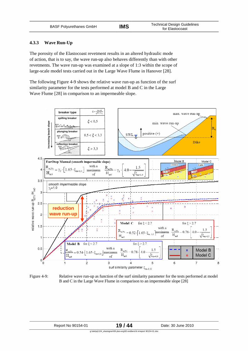
4.3.3 Wave Run-Up
The porosity of the Elastocoast revetment results in an altered hydraulic mode
of action, that is to say, the wave run-up also behaves differently than with other
revetments. The wave run-up was examined at a slope of 1:3 within the scope of
large-scale model tests carried out in the Large Wave Flume in Hanover [28].
The following Figure 4-9 shows the relative wave run-up as function of the surf
similarity parameter for the tests performed at model B and C in the Large
Wave Flume [28] in comparison to an impermeable slope.
reduction
wave run-up
breaker type
spilling breaker
reflection breaker
plunging breaker
inc
re
as
ing
be
ac
hs
lop
e
Figure 4-9: Relative wave run-up as function of the surf similarity parameter for the tests performed at model
B and C in the Large Wave Flume in comparison to an impermeable slope [28]

BASF Polyurethanes GmbH IMSTechnical Design Guidelines
for Elastocoast
Report No 90154-01 20 / 44 Date: 30 June 2010
g:\dat\prj\154_elastogran\08 plan-erg\83 endbericht e\report 90154-01.doc
The surf similarity parameter s a non-dimensional parameter provides
information on the breaking behaviour of the waves (cf. Figure 4-9). It is
defined as follows
0/
tan
LH
α
ξ =
and includes the slope angle tan wave steepness H/L0,
consisting of the wave height H and the wave length L0
in deep water. Small
surf similarity parameters stand for milder slope angles and spilling breakers,
large surf similarity parameters stand for steeper slopes and the corresponding
breaker types such as collapsing or surging breaker (cf. overview of breaker
types in Figure 4-9).
Figure 4-9 indicates that, according to the respective surf similarity parameter,
the wave run-up can be reduced by 25% and up to 50% with an Elastocoast
revetment (blue/red line in Figure 4-9) in comparison to an impermeable slope
(black line in Figure 4-9). The potential reduction of the wave run-up can be
taken into account when designing and planning an Elastocoast revetment.
Comparative values of the reduction coefficient for revetments with other
surfaces are specified in EAK (2002) in Table A 4.2.2. With regard to
comparative considerations, reference is made to the respective sections in EAK
(2002).

BASF Polyurethanes GmbH IMSTechnical Design Guidelines
for Elastocoast
Report No 90154-01 21 / 44 Date: 30 June 2010
g:\dat\prj\154_elastogran\08 plan-erg\83 endbericht e\report 90154-01.doc
4.3.4 Wave Run-Down
With regard to the wave run-down in case of an Elastocoast revetment, the tests
in the Large Wave Flume [28] can also be revert to.
In the following Figure 4-10, the test results for the wave run-down are shown
analogous to Section 4.3.3.
breaker type
spilling breaker
reflection breaker
plunging breaker
increasin
gb
each
slo
pe
Figure 4-10: Relative wave run-down as function of the surf similarity parameter for the tests at model B
and C in the Large Wave Flume in comparison to an impermeable slope [28]
BASF Polyurethanes GmbH IMSTechnical Design Guidelines
for Elastocoast
Report No 90154-01 22 / 44 Date: 30 June 2010
g:\dat\prj\154_elastogran\08 plan-erg\83 endbericht e\report 90154-01.doc
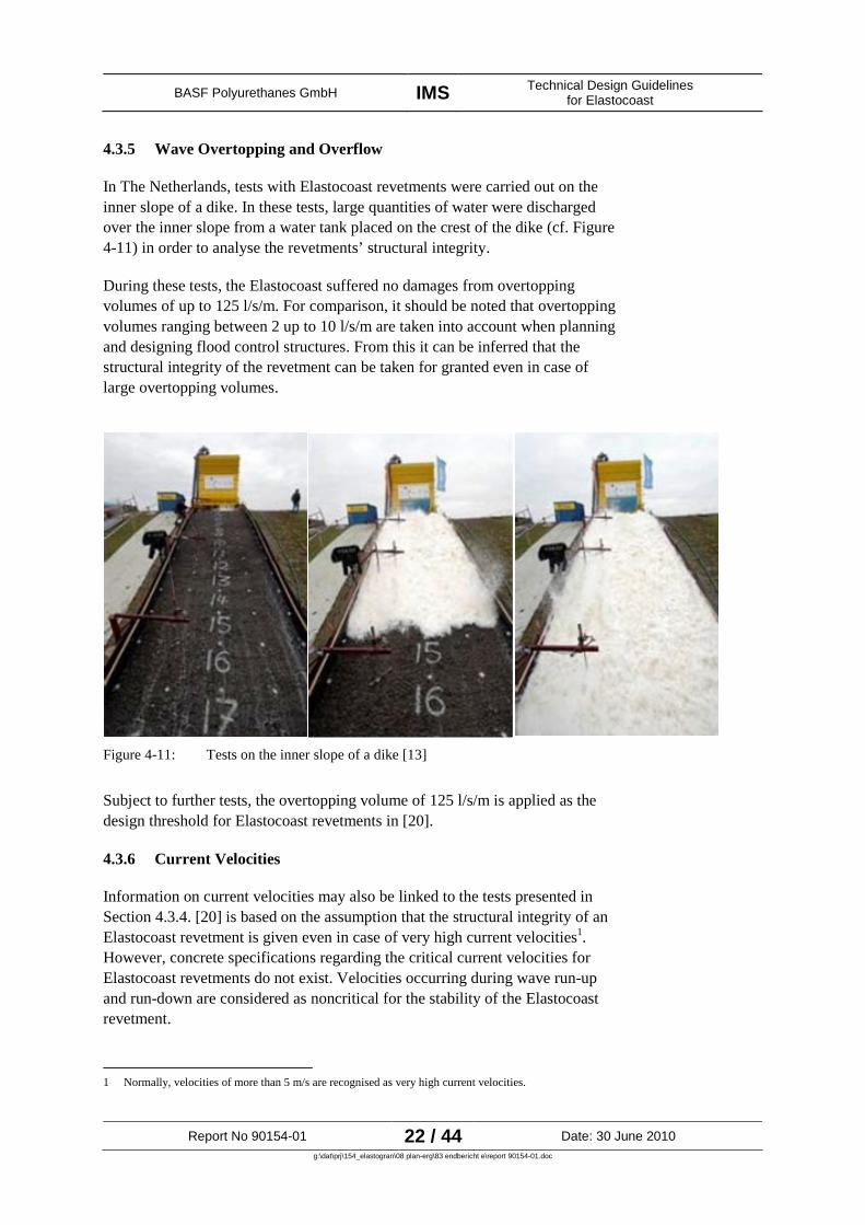
4.3.5 Wave Overtopping and Overflow
In The Netherlands, tests with Elastocoast revetments were carried out on the
inner slope of a dike. In these tests, large quantities of water were discharged
over the inner slope from a water tank placed on the crest of the dike (cf. Figure
4-11) in order to analyse the revetments’ structural integrity.
During these tests, the Elastocoast suffered no damages from overtopping
volumes of up to 125 l/s/m. For comparison, it should be noted that overtopping
volumes ranging between 2 up to 10 l/s/m are taken into account when planning
and designing flood control structures. From this it can be inferred that the
structural integrity of the revetment can be taken for granted even in case of
large overtopping volumes.
Figure 4-11: Tests on the inner slope of a dike [13]
Subject to further tests, the overtopping volume of 125 l/s/m is applied as the
design threshold for Elastocoast revetments in [20].
4.3.6 Current Velocities
Information on current velocities may also be linked to the tests presented in
Section 4.3.4. [20] is based on the assumption that the structural integrity of an
Elastocoast revetment is given even in case of very high current velocities1
.
However, concrete specifications regarding the critical current velocities for
Elastocoast revetments do not exist. Velocities occurring during wave run-up
and run-down are considered as noncritical for the stability of the Elastocoast
revetment.
1 Normally, velocities of more than 5 m/s are recognised as very high current velocities.

BASF Polyurethanes GmbH IMSTechnical Design Guidelines
for Elastocoast
Report No 90154-01 23 / 44 Date: 30 June 2010
g:\dat\prj\154_elastogran\08 plan-erg\83 endbericht e\report 90154-01.doc
4.3.7 Wave Reflection
With regard to the wave reflection of an Elastocoast revetment, tests in the
Large Wave Flume [28] can be revert to.
The following Figure 4-12 shows the reflection behaviour of an Elastocoast
revetment in comparison to a smooth slope and a two-layer rock armour. [28]
also states that the reflection coefficient depends on the wave period. For further
explanations, reference is made to [28]
Figure 4-12: Wave reflection of the Elastocoast revetment [28]
BASF Polyurethanes GmbH IMSTechnical Design Guidelines
for Elastocoast
Report No 90154-01 24 / 44 Date: 30 June 2010
g:\dat\prj\154_elastogran\08 plan-erg\83 endbericht e\report 90154-01.doc
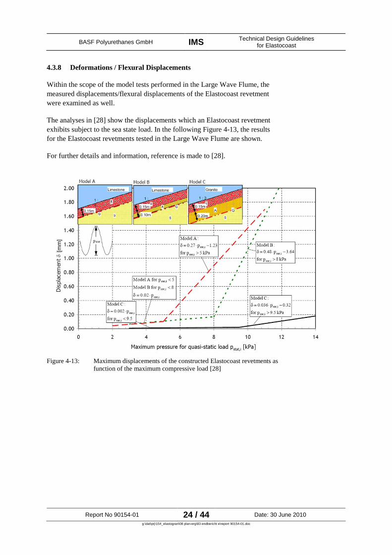
4.3.8 Deformations / Flexural Displacements
Within the scope of the model tests performed in the Large Wave Flume, the
measured displacements/flexural displacements of the Elastocoast revetment
were examined as well.
The analyses in [28] show the displacements which an Elastocoast revetment
exhibits subject to the sea state load. In the following Figure 4-13, the results
for the Elastocoast revetments tested in the Large Wave Flume are shown.
For further details and information, reference is made to [28].
[m
m]
Figure 4-13: Maximum displacements of the constructed Elastocoast revetments as
function of the maximum compressive load [28]

BASF Polyurethanes GmbH IMSTechnical Design Guidelines
for Elastocoast
Report No 90154-01 25 / 44 Date: 30 June 2010
g:\dat\prj\154_elastogran\08 plan-erg\83 endbericht e\report 90154-01.doc
4.3.9 Pore Pressures
Pore pressures are particularly important for the global structural integrity of the
Elastocoast revetment. Pore pressures beneath the revetment are caused by tide
fluctuations (nearly static processes) and sea state conditions (dynamic
processes).
With regard to the resulting pore pressures, it is differentiated between transient
and residual pore pressures (Figure 4-14).
Figure 4-14: Definition and differentiation of transient and residual pore pressures
[28]
Damping in the Soil Body
Pore pressures are damped in the soil body, i.e., as the depth in the soil body
increases, the pore pressure fluctuations decrease strongly.
The damping of the maximum wave-induced pore pressures is shown in the
following Figure 4-15.

BASF Polyurethanes GmbH IMSTechnical Design Guidelines
for Elastocoast
Report No 90154-01 26 / 44 Date: 30 June 2010
g:\dat\prj\154_elastogran\08 plan-erg\83 endbericht e\report 90154-01.doc
Figure 4-15: Relative pore pressure for different layers in the sand core beneath the Elastocoast revetment as
function of the surf similarity parameter [16], [28]
Stability Analysis for Loads to be Expected Due to Pore Pressures
When designing and dimensioning the Elastocoast revetment, it has to be
ensured that the occurring pore pressures (transient and residual) do not result in
liquefaction, shiftings and subsequent damages (cf. Case of Damage A during
the model tests in the Large Wave Flume [28]). This can be guaranteed by
sufficiently dimensioning the filter layer in consideration of the subsoil.
This proof can be furnished and/or examined by means of a stability analysis.
The basic principle of the vertical equilibrium of forces is shown in the
following Figure 4-16.

BASF Polyurethanes GmbH IMSTechnical Design Guidelines
for Elastocoast
Report No 90154-01 27 / 44 Date: 30 June 2010
g:\dat\prj\154_elastogran\08 plan-erg\83 endbericht e\report 90154-01.doc
Figure 4-16: Schematic representation of the vertical forces occurring during the stability analysis
In the end, the lift forces directed upwards due to the pore pressure must not
become larger than the forces directed downwards due to the dead weight of the
Elastocoast revetment and the soil. An exemplary result is provided in Figure
4-17. As soon as soil liquefaction appears in a soil layer beneath the revetment,
damages to the revetment have to be taken into account.
That is to say, the lift forces to be expected have to be bridged by sufficiently
dimensioning the cover layer and filter layer. If pore pressures have to be taken
into account as design parameters, the respective analysis has to be performed.
Figure 4-17: Exemplary result of the stability analysis

BASF Polyurethanes GmbH IMSTechnical Design Guidelines
for Elastocoast
Report No 90154-01 28 / 44 Date: 30 June 2010
g:\dat\prj\154_elastogran\08 plan-erg\83 endbericht e\report 90154-01.doc
Approximate Stability Analysis
ARCADIS (2009) assumes that, due to its porosity, the Elastocoast revetment is
well suited to discharge water level differences and pore water. Under the
assumption that the geotextile is becoming completely impermeable in the soil
due to redistributions of fines, [20] offers the possibility to estimate the required
revetment thickness by means of the design diagram in Figure 4-18. In addition
to this, a corresponding deterministic approach for determining the revetment
thickness is presented in [20] as well.
Figure 4-18: Design diagram of the cover layer thickness D in the event of overpressures as function of
the significant wave height Hs
[20]
4.3.10 Ice Loads
It is generally noted by [20] that ice and ice loads do not pose any problem for
Elastocoast revetments. Due to the relatively smooth surface of Elastocoast
revetments, ice loads cannot become concentrated at individual points and thus
cannot cause any damages.
The following details are provided by [20] with regard to the design of the
revetment:
– rough an uneven surfaces in the revetment design at which ice loads may
become concentrated are to be avoided.
– when planning revetments within areas in which ice loads may occur, slope
angles steeper than 1 : 3 should be avoided.
For further information on ice loads, reference is made to EAK (2002),
Recommendation A, Section 7.

BASF Polyurethanes GmbH IMSTechnical Design Guidelines
for Elastocoast
Report No 90154-01 29 / 44 Date: 30 June 2010
g:\dat\prj\154_elastogran\08 plan-erg\83 endbericht e\report 90154-01.doc
4.3.11 Traffic Loads
Basically, the Elastocoast revetments are designed for occasional traffic loads
which might, for example, occur within the scope of maintenance works. These
vehicles can exert heavy loads on the revetment.
Actual tests at an Elastocoast revetment were carried out with a chain dredger in
The Netherlands. Despite the rotating dredging movements, no significant
damages occurred on the surface of the revetment. For further information,
reference is made to [13].
In case of known traffic loads, ARCADIS (2009) recommends the following
approach for determining the required revetment thickness D for the Elastocoast
revetment.
Parameter
For a traffic load of 1,000 rides per year, a minimum revetment thickness of
– D = 0.20 m in case of a sand foundation and
– D = 0.25 m in case of a clay foundation
is recommended.
4.4 Design of the Revetment Structure
The design parameters specified in Section 4.3 and the design parameters
resulting and derived thereof in particular with regard to the revetment design
and thickness (cf. 3.4) are to be specified in the course of the dimensioning
which has to be carried out. Thus, a stability analysis for the revetments under
the occurring loads and the existing boundary conditions is available.
According to ARCADIS (2009), the cover layer thickness ranges between 0.1 m
and 0.5 m.
With reference to the model tests in the Large Wave Flume with the
documented case of damage [28] as well as the loads occurring at the
revetment, in particular wave and pore pressures (cf. Sections 4.3.2 and 4.3.9),
it is recommended to closely examine the necessity of a filter or levelling layer
beneath the cover layer.

BASF Polyurethanes GmbH IMSTechnical Design Guidelines
for Elastocoast
Report No 90154-01 30 / 44 Date: 30 June 2010
g:\dat\prj\154_elastogran\08 plan-erg\83 endbericht e\report 90154-01.doc
Recommendations on the Design of the Cover Layer
The design parameter for the cover layer thickness determined in Section 4.3
should be rounded to 5 cm.
With regard to the reference projects in Section 6, a minimum thickness of
0.15 m is recommended for the cover layer of the Elastocoast revetment.
According to Section 4.3 , the analysis of the required cover layer thickness has
to be performed also in consideration of the applied type of stones, i.e. in
particular the stone size (cf. Section 4.6.1).
Recommendations on the Design of the Filter or Levelling Layer
In case of Elastocoast revetments with a slope angle of 1:3 or steeper, a
minimum thickness of 0.15 m is recommended for the filter or levelling layer.
In case of milder slope angles, the question whether a filter or levelling layer is
necessary has to be examined in consideration of the existing hydraulic and
geotechnical boundary conditions, the applied stone sizes, the occurring loads
and the influencing processes. A respective analysis of the revetment stability
(cf. Section 4.3.9) has to be performed.
4.5 Notes on Construction Details for Transition Zones
The transitions to other structures and the borders of revetments are very
important areas with regard to the structural integrity of a revetment. They have
to be designed according to the existing boundary conditions as well. In an
extreme case, the transition details of a revetment may be decisive for the
structural integrity of the entire revetment.
ARCADIS (2009) states some particulars regarding the transition details of an
Elastocoast revetment which are shown in the following in Figure 4-19.
Further information on transition details may be gathered from the reference
projects or requested from the responsible authorities (see [13]). Figure 4-20
shows some transition details which were realised in the reference project on
Amrum.
Basic information on the design of revetments in transition zones to existing
structural components are also to be found in the codes and standards by the
BAW (cf. e.g. [7]).

BASF Polyurethanes GmbH IMSTechnical Design Guidelines
for Elastocoast
Report No 90154-01 31 / 44 Date: 30 June 2010
g:\dat\prj\154_elastogran\08 plan-erg\83 endbericht e\report 90154-01.doc
Figure 4-19: Exemplary transition details according to [20]
Figure 4-20: Transition details from the reference project on Amrum (Photos: IMS)
BASF Polyurethanes GmbH IMSTechnical Design Guidelines
for Elastocoast
Report No 90154-01 32 / 44 Date: 30 June 2010
g:\dat\prj\154_elastogran\08 plan-erg\83 endbericht e\report 90154-01.doc
4.6 Additional Information, Requirements and Properties
In the following, some further details on Elastocoast revetments are provided. In
general, reference is made to the statements provided by ARCADIS (2009) as
well as all other available documents and data to be found in Appendix 1.
4.6.1 Stone Types and Stone Sizes Used for Elastocoast Cover Layers
The chosen stone types and the respective grain sizes influence the cover layer
thickness. According to ARCADIS (2009), it is possible to use different stone
types for Elastocoast cover layers.
With regard to already applied stone types, it is referred to the reference projects
in Section 6, BASF PU as well as to [13] .
Basically, the cover layer should have a minimum thickness of
– 2 x D50
from a functional point of view
– 2.5 x Dmax
from a practical point of view
These minimum thicknesses are to be considered against the background of the
dimensioning of the cover layer thickness in Section 4.3.
The material properties of different revetment stones are specified more
precisely by ARCADIS (2009).
4.6.2 Upgrading of Existing Revetments
Basically, it is possible to upgrade existing revetments with an Elastocoast
revetment. In such cases, the planning and design of the Elastocoast revetment
are defined by the respective boundary conditions.
In Chapter 4.3.7, ARCADIS (2009) provides information on Elastocoast
revetments used to upgrade existing revetments. For this purpose, Elastocoast
has to be designed for the prevailing loads. ARCADIS (2009) assumes that no
permanent bonding between the Elastocoast revetment and the other revetment
may be applied. In this regard, reference is made to the associated deterministic
design approach in [20] and other reports and studies.
The LKN has made positive experiences regarding the combination of
Elastocoast revetments with existing rubble revetments in the reference project
on Amrum (cf. Figure 4-19).
It is also very easy to upgrade Elastocoast revetments.

BASF Polyurethanes GmbH IMSTechnical Design Guidelines
for Elastocoast
Report No 90154-01 33 / 44 Date: 30 June 2010
g:\dat\prj\154_elastogran\08 plan-erg\83 endbericht e\report 90154-01.doc
4.6.3 Resistance to Freeze and Thaw
The Prüfinstitut für Baustoffe and Umwelt GmbH has tested the resistance of
Elastocoast to freeze and thaw. According to the test results, Elastocoast is to be
judged as sufficiently resistant against freeze/thaw cycles (see [20]).
4.6.4 Removability
In the event of a removal of the Elastocoast revetment, the data, documents, etc.
on the topic “removal” listed in Appendix 1 are to be applied for the disposal
and subsequent use of Elastocoast [29].
With regard to this, it is stated in [12]:
“The composite composed of the fully cured polyurethane and stones can
be treated like conventional waste at the end of its life cycle. According to
the European Waste Catalogue EAK (German abbreviation) 070213, fully
cured polyurethane and stones do not have to be treated as hazardous
waste. If treated as demolition waste with a ratio of less than 5 vol. %
polyurethane, EAK 170117 or 170504 (mixture of cement, bricks, tiles or
ceramic) applies. In case of more than 5 vol. %, EAK 170904 (mixture of
construction site and demolition waste) is applied. It is possible to re-use
the composite material for road construction.”
4.6.5 Environmental Aspects
Environmental aspects wil not be addressed here in detail. With regard to this, a
number of studies and tests have been carried out on behalf of BASF PU. A
survey of the existing data and documents on ecology, ecotoxicology and water
quality is provided in Appendix 1.
In [12], reference is made to scientific studies on the return of vegetation and
other organisms to Elastocoast revetments in The Netherlands. As a result, it is
said that “the colonisation by microalgae and animals may take place quickly
and permanently under favourable conditions”.
4.6.6 Planting of Vegetation on Elastocoast Revetments
It is basically possible to plant vegetation on an Elastocoast revetment. With
regard to the revetment design, however, it is recommended to act on the
assumption of a reduced porosity and permeability of the Elastocoast revetment.
In this regard, reference is made to the sections on the design of Elastocoast
revetments subject to the existing geotechnical and hydraulic boundary
conditions. If vegetation is planted on Elastocoast revetments, the relevant
analyses have to be performed. An example for natural plantation on the Hallig
Nordstrandischmoor is provided in [12] (cf. Fig. 2.6.2.10).

BASF Polyurethanes GmbH IMSTechnical Design Guidelines
for Elastocoast
Report No 90154-01 34 / 44 Date: 30 June 2010
g:\dat\prj\154_elastogran\08 plan-erg\83 endbericht e\report 90154-01.doc
4.6.7 Additional Anchoring
If an Elastocoast revetment is strained by pore pressures accompanied by
possible subsoil displacements and a lifting of the revetment, it is generally
possible to use additional anchoring systems, e.g. ground anchors. The
respective details on the intended anchoring system and the associated analyses
have to be provided.
4.6.8 Porosity
The porosity of the Elastocoast revetment corresponds to the porosity of the
applied type of stones. The film of polyurethane coating the individual stones
does not reduce the porosity.
4.6.9 Resistance to UV Radiation
The resistance of Elastocoast to UV radiation was tested.
According to ARCADIS (2009), tests by BASF PU have shown that – after
3,000 h of exposure to UV light – no negative influence on the compressive
strength of the tested material was identifiable. This volume of exposure to UV
light corresponds to a three years period of real sun light exposure in Central
Europe.
Figure 4-21 shows the positive effect of sand applied on the surface of the
“fresh” Elastocoast revetment. The additional sand grains not only increase the
revetment’s accessibility but also protect it against UV radiation.
Figure 4-21: Resistance of Elastocoast to UV radiation
For further details, reference is made to [13] and [20].

BASF Polyurethanes GmbH IMSTechnical Design Guidelines
for Elastocoast
Report No 90154-01 35 / 44 Date: 30 June 2010
g:\dat\prj\154_elastogran\08 plan-erg\83 endbericht e\report 90154-01.doc
4.6.10 Resistance to Salt Water
The resistance of Elastocoast to salt water was analysed and confirmed by
means of an accelerated test procedure (EN ISO 2578). In the findings, it was
observed that Elastocoast is fully stable and resistant to sea water. Its life span
ranges between 80 and up to 100 years. For further details, reference is made to
[13] and [20].
Temperature
Tim
e i
n [
ye
ars
] to
th
eA
ch
ieve
me
nt
of
the
Lim
it V
alu
e
Lifetime expectation to the Achievement of the Limit Value
measured
extrapolated
Limit Value: tensile strength
Artificial Sea Water
Figure 4-22: Resistance of Elastocoast to salt water (in [20])

BASF Polyurethanes GmbH IMSTechnical Design Guidelines
for Elastocoast
Report No 90154-01 36 / 44 Date: 30 June 2010
g:\dat\prj\154_elastogran\08 plan-erg\83 endbericht e\report 90154-01.doc
5 Notes on the Planning, Design, Approval, Tendering and
Construction of an Elastocoast Revetment
5.1 General
In consideration of the design rules compiled in Section 4, it is possible to
design an Elastocoast revetment for given hydraulic, geotechnical and
constructional boundary conditions. In the following, some additional notes on
the planning, design, approval and construction of an Elastocoast revetment are
provided.
5.2 Planning and Design
The Elastocoast revetment can and must be designed in consideration of the basic
principles specified in Section 4.
In case the technical equivalence between a conventional revetment and an
Elastocoast revetment has to be established, the same course of action is to be
taken, i.e., the technical equivalence has to be established for the different
design parameters in consideration of the individual, known design parameters.
5.3 Approval
The approval of construction projects and measures in coastal protection has to
be obtained from the responsible Federal State authorities of the coastal states.
Details concerning questions relevant for approval may be inferred from the
document on hand. Further information is not known at present.
5.4 Tendering
The tendering stage for an Elastocoast revetment requires the design and
approval of said structure.
The invitation to tender has to refer precisely to the requested construction
method and the construction materials required in this regard. In addition to
this, it has to name the construction method as is the rule with the invitation to
tender for conventional revetments.
For the precise description of the material “Elastocoast”, BASF PU should be
contacted in order to clarify the exact specification.
In addition to this, it should be inquired in the invitation to tender whether the
executing construction company has already gained any experiences in building
of Elastocoast revetments. In any case, it should be considered and explicitly
tendered that consulting services are to be rendered by BASF PU during the
tender stage as well as the subsequent construction phase.
BASF Polyurethanes GmbH IMSTechnical Design Guidelines
for Elastocoast
Report No 90154-01 37 / 44 Date: 30 June 2010
g:\dat\prj\154_elastogran\08 plan-erg\83 endbericht e\report 90154-01.doc
5.5 Construction
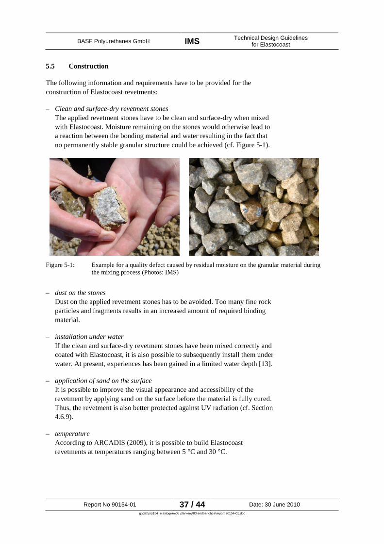
The following information and requirements have to be provided for the
construction of Elastocoast revetments:
– Clean and surface-dry revetment stones
The applied revetment stones have to be clean and surface-dry when mixed
with Elastocoast. Moisture remaining on the stones would otherwise lead to
a reaction between the bonding material and water resulting in the fact that
no permanently stable granular structure could be achieved (cf. Figure 5-1).
Figure 5-1: Example for a quality defect caused by residual moisture on the granular material during
the mixing process (Photos: IMS)
– dust on the stones
Dust on the applied revetment stones has to be avoided. Too many fine rock
particles and fragments results in an increased amount of required binding
material.
– installation under water
If the clean and surface-dry revetment stones have been mixed correctly and
coated with Elastocoast, it is also possible to subsequently install them under
water. At present, experiences has been gained in a limited water depth [13].
– application of sand on the surface
It is possible to improve the visual appearance and accessibility of the
revetment by applying sand on the surface before the material is fully cured.
Thus, the revetment is also better protected against UV radiation (cf. Section
4.6.9).
– temperature
According to ARCADIS (2009), it is possible to build Elastocoast
revetments at temperatures ranging between 5 °C and 30 °C.

BASF Polyurethanes GmbH IMSTechnical Design Guidelines
for Elastocoast
Report No 90154-01 38 / 44 Date: 30 June 2010
g:\dat\prj\154_elastogran\08 plan-erg\83 endbericht e\report 90154-01.doc
– humidity
Basically, humidity does not pose any problems provided it does not have
any influence on the existing moisture remaining on the applied stones.
– working direction
When building an Elastocoast revetment, it is recommended to construct it in
load bearing direction (cf. Figure 5-2).
Figure 5-2: Recommendations for the design of transition zones and internal
transitions when constructing Elastocoast revetments according to [20]
Processing Notes
The manufacturer BASF PU gives the following notes on how to process
Elastocoast:
1. Dry weather conditions
– no precipitation
– ambient temperature at least 10 °C
2. The stones have to be delivered dry and preferably washed
– no dirt on the stones
3. The mixer has to be dry
4. The subsoil has to be prepared according to the planning specification
5. The specified stone quantity has to be determined and filled in the mixer.
Example: 33 kg of PU / 1 m³ of stones (approx. 3 vol. %)
6. B components have to be poured into A components and mixed together
– safety data sheets have to be observed
– protective clothing has to be worn!
7. The ready mixed adhesive has to be added to the stones and tumbled
8. The stone/adhesive mixture has to be applied and distributed on the
designated area
9. Sand has to be applied to the revetment.
10. If the construction process is interrupted, the mixer has to be mechanically
cleaned with new, dry stones.

BASF Polyurethanes GmbH IMSTechnical Design Guidelines
for Elastocoast
Report No 90154-01 39 / 44 Date: 30 June 2010
g:\dat\prj\154_elastogran\08 plan-erg\83 endbericht e\report 90154-01.doc
Recommendation
In order to ensure quality control, it is recommended that the manufacturer
BASF PU renders consulting services and/or technically monitors the
construction works.
Construction companies with, to date, no experience regarding the application
of Elastocoast may gain experience in advance through BASF PU. This
represents another quality management component.
5.6 Monitoring
Monitoring programmes for individual Elastocoast revetments were already
performed. The respective particulars on how to proceed when carrying out
monitoring measures are provided by ARCADIS (2009), Chapter 6.
BASF Polyurethanes GmbH IMSTechnical Design Guidelines
for Elastocoast
Report No 90154-01 40 / 44 Date: 30 June 2010
g:\dat\prj\154_elastogran\08 plan-erg\83 endbericht e\report 90154-01.doc
6 Reference Projects
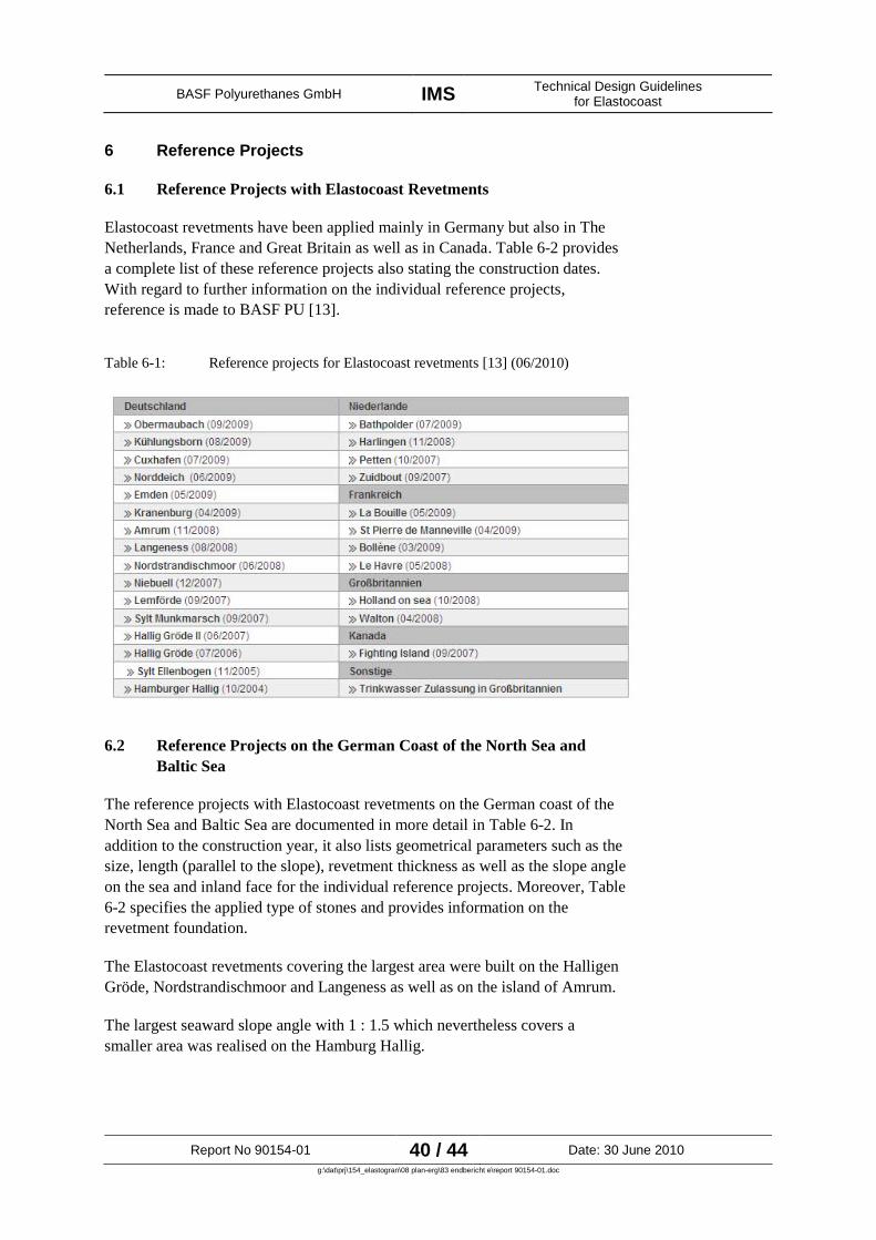
6.1 Reference Projects with Elastocoast Revetments
Elastocoast revetments have been applied mainly in Germany but also in The
Netherlands, France and Great Britain as well as in Canada. Table 6-2 provides
a complete list of these reference projects also stating the construction dates.
With regard to further information on the individual reference projects,
reference is made to BASF PU [13].
Table 6-1: Reference projects for Elastocoast revetments [13] (06/2010)
6.2 Reference Projects on the German Coast of the North Sea and
Baltic Sea
The reference projects with Elastocoast revetments on the German coast of the
North Sea and Baltic Sea are documented in more detail in Table 6-2. In
addition to the construction year, it also lists geometrical parameters such as the
size, length (parallel to the slope), revetment thickness as well as the slope angle
on the sea and inland face for the individual reference projects. Moreover, Table
6-2 specifies the applied type of stones and provides information on the
revetment foundation.
The Elastocoast revetments covering the largest area were built on the Halligen
Gröde, Nordstrandischmoor and Langeness as well as on the island of Amrum.
The largest seaward slope angle with 1 : 1.5 which nevertheless covers a
smaller area was realised on the Hamburg Hallig.

BASF Polyurethanes GmbH IMSTechnical Design Guidelines
for Elastocoast
Report No 90154-01 41 / 44 Date: 30 June 2010
g:\dat\prj\154_elastogran\08 plan-erg\83 endbericht e\report 90154-01.doc
Granite gravel and iron silicate gravel with sizes ranging between 20/40 mm
and 50/60 mm were used.
A geotextile base was normally used as foundation.
Table 6-2: Overview of the most important reference projects of Elastocoast revetments on the North Sea
and Baltic Sea stating essential revetment parameters
Project Name
Year of
Construc-
tion
Area
[m²]
Length
[m]
Thick-
ness
[cm]
Seaward
slope
[1 : m]
Inland
slope
[1 : m]
Material Foundation
North Sea
Sylt Ellenbogen 2005 270 25 - 30 1 : 10 --
iron silicate
stones
sand
with geotextile
Hallig Gröde I 2006 500 -- 25 1 : 3 1 : 3
granite gravel
50/60
rubble
with geotextile
Hallig Gröde II 2007 3,000 500 25 1 : 3 1 : 3
granite gravel
50/60
rubble
with geotextile
Hamburg Hallig 2008 120 -- 30 1 : 1.5 1 : 1 no specifications
existing
rubble core
Amrum 2008 1,875 254 15 1 : 3 --
granite gravel
20/40
geotextile
base
Hallig
Nordstrandischmoor
2008 1,800 -- -- -- --
granite gravel
40/60
rubble core/
geotextile
Hallig Langeness 2008 1,500 -- -- -- --
granite gravel
40/60
rubble core/
geotextile
Baltic Sea
Kühlungsborn 2009 100 -- -- -- --
granite gravel
32/64
geotextile
base
In case of the reference project on the Hallig Langeness, the existing seaward
revetment was raised with an Elastocoast revetment in form of a mound to a
triangular-shaped elevation (cf. Figure 6-1). The existing revetment as well as a
newly laid geotextile base were used as foundation.
With regard to the hydraulic mode of action, reference is made to Figure 2-4.
Due to its porosity, the Elastocoast revetment is able to “swallow” part of the
water quantities arising during wave run-up.
In this case, it is possible – due to the porosity of the Elastocoast revetment (cf.
Section 4.6.8) – that water resulting from wave run-up can be transported to the
inland face of the revetment and to the Hallig foreland. Amongst other things,
this also has the positive effect that waves breaking over the mound in the event
of a continuously increasing water level, break into an existing water cushion
which has a highly damping i.e. positive effect from a hydraulic point of view.

BASF Polyurethanes GmbH IMSTechnical Design Guidelines
for Elastocoast
Report No 90154-01 42 / 44 Date: 30 June 2010
g:\dat\prj\154_elastogran\08 plan-erg\83 endbericht e\report 90154-01.doc
Existing Situation Elastocoast revetment
Figure 6-1: Existing situation and Elastocoast revetment on the Hallig Langeness (Photos: LKN)
6.3 Large-Scale Model Tests in the Large Wave Flume
Large-scale model tests with Elastocoast revetments were performed on a slope
with a 1 : 3 increase in the Large Wave Flume in Hanover (cf. Figure 6-2).
The systematic tests include, amongst others, the hydraulic effectiveness of the
revetment (wave run-up, reflection behaviour, impact loads beneath the
revetment, damping), mechanical effects due to hydraulic loads and strains
(movements/ displacements of the revetment) as well as the analyses of the
geotechnical boundary conditions (pore overpressures, soil liquefaction).
In the tests with model A (Elastocoast cover layer with a thickness of 0.15 m on
geotextile), the cover layer failed. The subsequent analysis showed that pore
overpressures in the subsoil beneath the revetment led to liquefaction and a
resulting displacements of the subsoil which, in the end, caused a revetment
failure for model A. With regard to further explanations and analyses of the
failure, reference is made to [28].
In comparison to the two models B and C, it is pointed out that a sufficient self
weight of the revetments (equal to the revetment thickness) is necessary, in
particular, in case of steeper slope angles.
Here, reference is made to the documentation of the results in [28].

BASF Polyurethanes GmbH IMSTechnical Design Guidelines
for Elastocoast
Report No 90154-01 43 / 44 Date: 30 June 2010
g:\dat\prj\154_elastogran\08 plan-erg\83 endbericht e\report 90154-01.doc
0.00
Figure 6-2: Analyses of Elastocoast revetments in the Large Wave Flume in
Hanover [28]

BASF Polyurethanes GmbH IMSTechnical Design Guidelines
for Elastocoast
Report No 90154-01 44 / 44 Date: 30 June 2010
g:\dat\prj\154_elastogran\08 plan-erg\83 endbericht e\report 90154-01.doc
7 Concluding Remarks
The report on hand presents the technical design guidelines for an Elastocoast
revetment on the basis of available information, data and documents. In this
connection, the reports by ARCADIS (2009) and LWI (2010) have to be named
as a matter of priority. The documented design guidelines mainly focus on
revetments in coastal and estuary areas.
Within the scope of the preparation of this report, IMS held talks with the
relevant authorities responsible for coastal protection. As a result, these
authorities are quite open to new methods in coastal protection. This can also be
inferred from the existing reference projects.
During the talks with the authorities, it became clear that two basic issues
repeatedly came to the foreground with regard to an application of Elastocoast
revetments in coastal areas: The possibility to install Elastocoast under water
and to the required total volume for the Elastocoast revetment. In addition to
this, the Elastocoast revetment is also regarded in connection with the existing
subsoil. LWI (2010) basically reports on the hydraulic and geotechnical
parameters as well as processes acting on and beneath an Elastocoast revetment
and the design parameters which can be derived from this. Therefore, the results
of LWI are included in the present design guidelines.
Another point discussed concerned the flexibility of the Elastocoast revetment.
Due to the composite effect, the material on the whole is not as flexible as loose
revetments and, thus, cannot react so elastically to movements of the area and
washouts. This characteristic of the Elastocoast revetment has to be taken into
account accordingly within the scope of the planning and design.
Elastocoast has already been used very successfully at some coastal sections
e.g. in Schleswig-Holstein. This applies in particular to the protection of the
Halligen (e.g. triangular-shaped, raised structure on the Hallig Langeness).
Here, Elastocoast is already recommended by the LKN as a construction
method in the field of coastal protection. So far, the experiences are very
positive.
Hamburg, 30th
June 2010
IMS Ingenieurgesellschaft mbH
signed Peters signed Teschke
BASF Polyurethanes GmbH IMSTechnical Design Guidelines for Elastocoast
Appendices
Report No 90154-01
g:\dat\prj\154_elastogran\08 plan-erg\83 endbericht e\report 90154-01.doc
Appendices
Appendix 1 Compilation of the Existing Documents
on Elastocoast and its Application in
Revetment Construction
Appendix 2 Design Diagrams on the Wave Height,
Excerpts from [20]
Appendix 3 Further Information on the Design of
the Elastocoast Revetment on the
Wave Height, Annex 1 from [20]

BASF Polyurethanes GmbH IMSTechnical Design Guidelines for Elastocoast
Appendices
Report No 90154-01
g:\dat\prj\154_elastogran\08 plan-erg\83 endbericht e\report 90154-01.doc
Appendix 1
Compilation of the Existing Documents on
Elastocoast and its Application in Revetment
Construction

BASF Polyurethanes GmbH IMSTechnical Design Guidelines for Elastocoast
Appendices
Report No 90154-01 1 / 3g:\dat\prj\154_elastogran\08 plan-erg\83 endbericht e\report 90154-01.doc
Available Documents on Elastocoast
General Documents
[12] Elastocoast – Innovative Technologie im Küstenschutz ... heute und morgen, Informationen,
Referenzen und Dokumente, BASF, Issue 2008
[13] BASF Polyurethanes GmbH, information on the web,
http://www.polyurethanes.basf.de/pu/Coastal-Defense
[14] BASF Polyurethanes GmbH, Informationsbroschüre Elastocoast - Alles, was Sie über
modernen Küstenschutz wissen müssen, 2010
[15] Polyurethane-Schotter-Verbund für Küstenschutzdeckwerke, Bautechnik 87 (2010), Issue 6
[16] BASF Polyurethanes GmbH, Veranstaltung Zukunftsichere Küsten mit innovativen
Materialien, Information day in the Town of Husum and the Island of Amrum, 10/11 May
2010, Presentation of lectures
Technology
[17] BASF PU, Technische Merkblatt, Elastocoast 6551/100, 6 June 2006
[18] Gu (2007) Hydraulic Properties PUR-Revetments compared to those of open Stone Asphalt
Revetment, TU Delft, Msc. Thesis Report, 08/2007
[19] Bijlsma (2008) The Elastocoast System – A study of possible failure mechanisms, TU Delft,
Msc. Thesis report, 09/2008
[20] ARCADIS (2009) Polyurethane bounded aggregate revetment, Design Manual, 14 September
2009
[21] FZK (2009) Large-scale model test on Elastocoast revetment in GWK, Presentation to the
Demonstration test on the 16th
June 2009
[22] Elastomeric Revetments with ElastoCoast – Its Perspectives in River and Coastal Protection-
Presentation by Pasche / Evertz
[23] TUHH (2008) Fortführung wissenschaftliche Untersuchungen an ElastoCoast-Pilotanlagen in
Schleswig-Holstein, Final Report, 31 July 2008
[24] TUHH (2005) Elastomerische Deckwerke, Eigenschaften – Bemessung – Anwendung, Draft
by Evertz, July 2005
[25] Hübsch (2004) Ableitung der maßgebenden Angriffskräfte auf die Tragkonstruktion eines
Polyurethan-verklammerten Deckwerks auf der Basis von Naturmessungen, TUHH,
Dissertation, March 2004

BASF Polyurethanes GmbH IMSTechnical Design Guidelines for Elastocoast
Appendices
Report No 90154-01 2 / 3g:\dat\prj\154_elastogran\08 plan-erg\83 endbericht e\report 90154-01.doc
[26] Klauder (2004) Ermittlung der Grenzwiderstandskräfte der Tragkonstruktion einer
Polyurethan-verklammerten Steinschüttung auf der Basis experimenteller Untersuchungen,
TUHH, Dissertation, March 2004
[27] Evertz (2009) Verfestigung von Deckwerken mit Polyurethan, Dissertation, Hamburg
University of Technology (TUHH), Institute of Hydraulic Engineering
[28] LWI (2010) Hydraulic Performance, Wave Loading and Response of Elastocoast Revetments
and their Foundation – A Large Scale Model Study -, Leichtweiß-Institut für Wasserbau, LWI
Report No. 988, Final Report, 8 January 2010
Removal – Waste Classification and Disposal
[29] Elastogran GmbH (2005) Die Entsorgung von Abfällen aus der Polyurethan-Herstellung und –
Verarbeitung in der Bundesrepublik Deutschland, 06/2005
[30] Länderarbeitsgemeinschaft Abfall (2003) LAGA-Merkblatt: Anforderungen an die Stoffliche
Verwertung von mineralischen Reststoffen/Abfällen – Technische Regeln, 5th
Edition, 6
November 2003
Ecology
[31] Pilots Elastocoast, results for the storm season 2007/2008, Egon Bijlsma, Marcelle Lock,
ARCADIS
[32] Early colonization of littoral communities on polyurethane substrates, A field and laboratory
study, Marcelle Lock, ARCADIS
[33] Ecological Research Elastocoast, Dutch Pilot Locations Petten and the Zuitbout, Report,
Marcelle Lock
Ecotoxicology
[34] Elastogran GmbH (2008) Bewertung des Einflusses von ausgehärtetem Elastocoast 6551/100
auf aquatische Ökosysteme, Letter by Dr T. Schupp from the 13th
November 2008
[35] Institut Fresenius (2007) Anwendungstest: Elastocoast 6551/100, Test Report No 331466 from
the 18th
May 2007
[36] Fraunhofer Institut Molekularbiologie und Angewandte Ökologie (2009) Study Plan: Alga,
Growth Inhibition Test, 23 April 2009
[37] Fraunhofer Institut Molekularbiologie und Angewandte Ökologie (2009) Study Plan:
Zebrafish, Fish EmbryoToxicity Test, 23 Aril 2009
[38] Fraunhofer Institut Molekularbiologie und Angewandte Ökologie (2009) Study Plan: Daphnia
magna, Reproduction test (OECD 211), 17 April 2009

BASF Polyurethanes GmbH IMSTechnical Design Guidelines for Elastocoast
Appendices
Report No 90154-01 3 / 3g:\dat\prj\154_elastogran\08 plan-erg\83 endbericht e\report 90154-01.doc
[39] Fraunhofer Institut Molekularbiologie und Angewandte Ökologie (2009) Study Plan:
Sediment – water chironomid toxicity test using spiked water (OECD 219), 17 April 2009
[40] Fraunhofer Institut Molekularbiologie und Angewandte Ökologie (2009) Study Plan:
Pseudomonas putida Growth Inhibition Test, 22 April 2009
Water Quality
[41] Drinking Water Inspectorate (2009) Approval given under regulation 31(4)(a) of the water
supply (water quality) regulations 2000 No. 3184 and of the water supply (water quality)
regulations 2001 (Wales) No. 3911, Letter from the 27th
April 2009
[42] Elastogran GmbH (2009) Instruction for use (IFU), Application of Elastocoast 6551/100 for
water reservoirs before treatment, Issue No. 1.3, 5 May 2009
[43] Elastogran GmbH (2008) Water regulations advisory scheme, BS6920 Test on effect of water
quality, product: Elastocoast 6551/100, 11 November 2009
[44] Elastogran GmbH (2008) Water regulations advisory scheme, BS6920 Test on effect of water
quality, product: Elastocoast 6551/102, 9 December 2009
[45] Elastogran GmbH (2008) Water regulations advisory scheme, BS6920 Test on effect of water
quality, product: Elastocoast 6551/103, 9 December 2009

BASF Polyurethanes GmbH IMSTechnical Design Guidelines for Elastocoast
Appendices
Report No 90154-01
g:\dat\prj\154_elastogran\08 plan-erg\83 endbericht e\report 90154-01.doc
Appendix 2
Design Diagrams on the Wave Height, Excerpts
from [20]
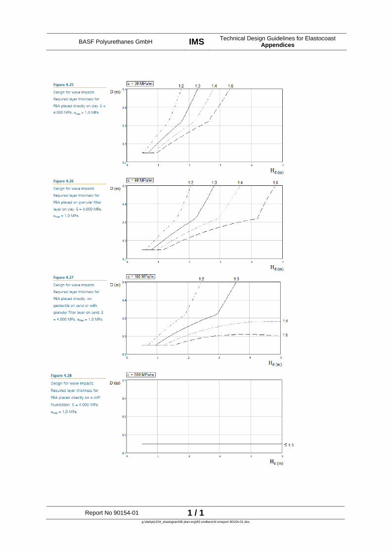
BASF Polyurethanes GmbH IMSTechnical Design Guidelines for Elastocoast
Appendices
Report No 90154-01 1 / 1g:\dat\prj\154_elastogran\08 plan-erg\83 endbericht e\report 90154-01.doc

BASF Polyurethanes GmbH IMSTechnical Design Guidelines for Elastocoast
Appendices
Report No 90154-01
g:\dat\prj\154_elastogran\08 plan-erg\83 endbericht e\report 90154-01.doc
Appendix 3
Further Information on the Design of the Elastocoast
Revetment on the Wave Height, Annex 1 from [20]

POLYURETHANE BONDED AGGREGATE REVETMENTS
073962493:A ARCADIS 65
ANNEX 1 Backgrounds for the design for wave impacts
Schematization method
Analogous to asphaltic revetments the PBA structure will be schematized as a plate on
linear-elastic foundation (TAW, 2002) [lit. 14]. The plate is loaded by a wave impact,
schematized as a triangular distributed load q(x) with a maximum of Pmax and a base width
equal to H.
The determination of design plate thickness is done in three steps:
Step 1: Determination of design wave impact load
Step 2: Choice of representative material parameters
Step 3: Determination of required plate thickness
Below a short description is given on choices and actions taken with each step. This section
ends with some pre-calculated graphs that can be used for design.
Step 1: Determination of design wave impact load
Schematized wave impact pressureFor wave impacts the design wave height Hd should be chosen sufficiently high such that the
chance of exceedence of this wave height is acceptable. The wave impact load is
schematized as a triangular load with a base width equal to Hd. The maximum impact
pressure occurs in the middle of the wave load and is estimated with the following
equation.
max w dP g q H
Where:
ρw = mass density of water [kg/m3]
g = gravitational acceleration [m/s2]
q = wave impact parameter [-]
Hd = design wave height [m]
Figure A1.1
Schematization of the wave
impact by a triangular load
(TAW, 2002).
Appendix 3, page 1 / 9

POLYURETHANE BONDED AGGREGATE REVETMENTS
073962493:A ARCADIS 66
Wave impact parameter q
In the wave impact parameter q both the probability of an incoming wave resulting in a
wave impact and the severity of that impact are incorporated. The probability density
function for the impact parameter, valid for a slope of 1:4, is given in figure A1.2.
Values for the wave impact parameter have been found empirically for slopes of 1:4. For
design calculations a conservative value of qr = 5.0 is chosen. This value corresponds with a
probability of exceeding of approximately 2%.
Figure A1.3 shows the impact pressure Pmax as a function of design wave height Hd,
dependent on the choice for q.
The value for the parameter q depends on the slope angle. Values for other slopes can be
derived as follows (TAW, 2002):
tan0.25 rq q
In which:
qa = wave impact parameter for a slope angle α [-]
tan α = tangent slope angle [-]
0.25 = tangent of the slope 1:4 [-]
qr = wave impact parameter for a slope 1:4 [-]
Figure A1.2
Probability density function of
the wave impact parameter q
for slopes of 1:4 (TAW, 2002).
Figure A1.3
Relation between wave height
and maximum impact pressure,
for a 1:4 slope.
Appendix 3, page 2 / 9
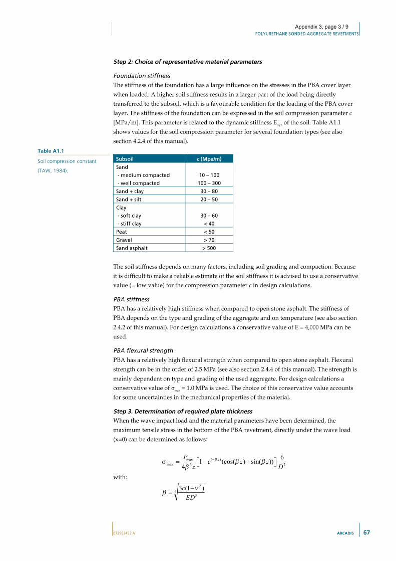
POLYURETHANE BONDED AGGREGATE REVETMENTS
073962493:A ARCADIS 67
Step 2: Choice of representative material parameters
Foundation stiffnessThe stiffness of the foundation has a large influence on the stresses in the PBA cover layer
when loaded. A higher soil stiffness results in a larger part of the load being directly
transferred to the subsoil, which is a favourable condition for the loading of the PBA cover
layer. The stiffness of the foundation can be expressed in the soil compression parameter c
[MPa/m]. This parameter is related to the dynamic stiffness Edyn of the soil. Table A1.1
shows values for the soil compression parameter for several foundation types (see also
section 4.2.4 of this manual).
Subsoil c (Mpa/m)
Sand
- medium compacted
- well compacted
10 � 100
100 � 300
Sand + clay 30 � 80
Sand + silt 20 � 50
Clay
- soft clay
- stiff clay
30 � 60
< 40
Peat < 50
Gravel > 70
Sand asphalt > 500
The soil stiffness depends on many factors, including soil grading and compaction. Because
it is difficult to make a reliable estimate of the soil stiffness it is advised to use a conservative
value (= low value) for the compression parameter c in design calculations.
PBA stiffnessPBA has a relatively high stiffness when compared to open stone asphalt. The stiffness of
PBA depends on the type and grading of the aggregate and on temperature (see also section
2.4.2 of this manual). For design calculations a conservative value of E = 4,000 MPa can be
used.
PBA flexural strength
PBA has a relatively high flexural strength when compared to open stone asphalt. Flexural
strength can be in the order of 2.5 MPa (see also section 2.4.4 of this manual). The strength is
mainly dependent on type and grading of the used aggregate. For design calculations a
conservative value of σmax = 1.0 MPa is used. The choice of this conservative value accounts
for some uncertainties in the mechanical properties of the material.
Step 3. Determination of required plate thicknessWhen the wave impact load and the material parameters have been determined, the
maximum tensile stress in the bottom of the PBA revetment, directly under the wave load
(x=0) can be determined as follows:
( )maxmax 3 2
61 (cos( ) sin( ))4
zPe z z
z D
with:2
43
3 (1 )cED
Table A1.1
Soil compression constant
(TAW, 1984).
Appendix 3, page 3 / 9

POLYURETHANE BONDED AGGREGATE REVETMENTS
073962493:A ARCADIS 68
In which:
σmax = flexural moment capacity [MPa]
Pmax = maximum pressure of schematized wave load [MPa]
c = coefficient of compression of subsoil [MPa/m]
E = Young’s modulus of the cover layer [MPa]
D = thickness of the cover layer [m]
ν = constant of Poisson (assumed to be ν =0.35) [-]
z = half the triangular load width, z=0.5H [m]
H = wave height [m]
In figure A1.3 an example is given of the resulting relation between plate thickness and
actual tensile stress. The curve in figure A1.4 shows a local maximum (in this case at a plate
thickness of approximately 0.10 m and a tensile stress of 1.2 MPa). Only points at the right
hand side from this local maximum (i.e. thicknesses larger than 0.10 m), may be used for
design calculations.
The basic assumption is made that the macroscopic properties of the plate apply if the
thickness of the plate is not smaller than a predefined number of stone sizes Dn50. It is
assumed that a thickness of at least 8 times Dn50 is required for the plate to reach full design
flexural strength. For smaller plate thicknesses the maximum tensile stress is found by linear
interpolation. Figure A1.5 shows the resulting design strength in relation to plate thickness,
for aggregate with a grading of 30/60 mm, Dn50 = 40 mm.
Figure A1.4
Actual tensile stress as a
function of plate thickness for:
Hd = 2.5 m
q = 5.0
c = 30 MPa/m
E = 4,000 MPa
Appendix 3, page 4 / 9

POLYURETHANE BONDED AGGREGATE REVETMENTS
073962493:A ARCADIS 69
Finally, in order to determine the minimum required plate thickness given the input wave
load and material parameters, the calculated maximum tensile stress is equalled to the
design flexural strength. This can best be done visually, as shown in figure A1.5. It is
important that the intersection of the two lines is at the right of the local maximum of the
local maximum in the actual tensile strength curve.
Pre-calculated design graphsThe calculation and graphical presentation of the actual tensile stress as a function of plate
thickness cannot easily be performed by hand calculation. Below, several typical scenario’s
are pre-calculated for use in preliminary design of PBA structures. Together with the
definition of acceptable tensile strength given above, these graphs can be used to quickly
determine the minimum required plate thickness. Also, in section 4.3.3 of this manual
design graphs are given relating design wave height to layer thickness.
Figure A1.5
Assumed development of
flexural strength as a function
of plate thickness.
Figure A1.5
Graphical determination of
required layer thickness.
Appendix 3, page 5 / 9

POLYURETHANE BONDED AGGREGATE REVETMENTS
073962493:A ARCADIS 70
Figure A1.6
Pre-calculated stress curves for
c = 30 MPa/m, E = 4,000 MPa,
Appendix 3, page 6 / 9

POLYURETHANE BONDED AGGREGATE REVETMENTS
073962493:A ARCADIS 71
Figure A1.7
Pre-calculated stress curves for
c = 60 MPa/m. E = 4,000 MPa.
Appendix 3, page 7 / 9

POLYURETHANE BONDED AGGREGATE REVETMENTS
073962493:A ARCADIS 72
Figure A1.8
Pre-calculated stress curves for
c = 100 MPa/m. E = 4,000
MPa.
Appendix 3, page 8 / 9

POLYURETHANE BONDED AGGREGATE REVETMENTS
073962493:A ARCADIS 73
Figure A1.9
Pre-calculated stress curves for
c = 500 MPa/m. E = 4,000
MPa.
Appendix 3, page 9 / 9

INGENIEURGESELLSCHAFT MBH
Main and Branch Office Branch Office
Branch Office Hamburg Frankfurt/M Schleswig-Holstein
Stadtdeich 7 An der Gehespitz 50 Ulmenweg 12
20097 Hamburg 63263 Neu-Isenburg 25492 Heist
GERMANY GERMANY GERMANY
Phone: +49 40 32818-0 Phone: +49 6102 45-3600 Phone: +49 04122 907054
Fax: +49 40 32818-139 Fax: +49 6102 45-3636 Fax: +49 04122 907053
E-Mail: [email protected] E-Mail: [email protected] E-Mail [email protected]