Embed Size (px)
Citation preview

HERON Vol. 52 (2007) No. 3 165
Elastic compressive-flexural-torsional
buckling in structural members
W.J. Raven, J. Blaauwendraad and J.N.J.A. Vamberský
Faculty of Civil Engineering and Geosciences, Delft University of Technology, the Netherlands 1
This article presents insight into the stability check for members loaded in a combination of
compression and bending, in which - due to 2nd-order effects - also torsion occurs. A key
decision in the opinion of the authors is the introduction of the stability parameter n* as the
ratio of the total displacement and the 2nd-order part of displacement. They believe that this
quantity can fulfill an 'alarming function' when judging the stability of structural members.
An iteration procedure in a number of clearly distinct steps results into a general formula for
n*, in which all necessary data concerning member properties and load cases are covered.
The member safety is inspected by a unity check, which relates occurring stresses to strength
requirements. Also checks on displacement limits are described.
This new method for compressive-flexural-torsional buckling is applicable for all existing
building materials in structural engineering as long as elasticity is involved.
Essentially, the calculations can be done in a short time using a pocket calculator, without
the use of other utilities. It has been deliberately chosen not to elaborate the derived
formulas too far, in order to preserve a clear view on cohesion and procedure.
Key words: Building structures, structural members, stability, strength, stiffness, column
buckling, flexural-torsional buckling, bending, twist
1 Introduction
The assessment of the stability, stiffness and strength of members loaded in bending and
compression mostly yields complicated analyses, in which an effective combination of
simplicity and accuracy often is not possible. In the course of years several advanced
1 This article is based on the doctoral thesis of the first author, which he completed in 2006 at
Delft University of Technology under supervision of the two other authors [14].
166
methods have been developed, which facilitate the simulation of the flexural-torsional
buckling and/or column buckling of (members of) structures.
Early studies were done in the USA by Timoshenko [1], Timoshenko and Geere [2], Bleich
[3], later on followed by a fundamental work of Chen and Atsuta [4] and an even more
recent American/Italian work of Bazant and Cedolin [5]. Part of the book of Chen and
Atsuta was contributed by the Australian author Trahair, who himself also wrote a book
on flexural-torsional buckling [6]. Series of German studies can be reported, written by
Brüninghoff [7], Blass [8], Pauli [9], and Lohse [10] as well as a Norwegian contribution
from Eggen [11], the contribution from Van der Put to the Dutch timber code [12] and a
Dutch contribution from Van Erp [13]. Some of studies referred to are based on a more or
less complete set of differential equations; others start from virtual work considerations
and series development of displacement fields. Some result in closed-form solutions,
others apply numerical methods.
In case differential equations are used, they are in great majority linear ones. One of the
rare exceptions is reported by Trahair [6] and also in Chen et al. [4], where nonlinear
equations appear to yield improved results, which are in most cases more efficient than
achieved by the linear equations. The nonlinear equations take account of the effect of the
displacement in the direction of the major cross-section axis. The linear approach is
conservative for members with a major stiffness direction, which is dominant over the
stiffness in the minor direction and the twisting stiffness. As a consequence, timber beam
sections and I-shaped or H-shaped steel sections can safely be studied by the linear
approach. So, this will be done in the present study. The advanced nonlinear approach
only needs to be applied in case of more or less square box sections, which are out of scope
here. For such sections displacement in the major stiffness direction is not small if
compared to the lateral displacement, hence, therefore its effect can not be neglected
anymore.
In view of so many studies based on the classic linear starting points, why, yet, a new
approach to this issue? The answer to this question results from the experience that
application of tools, supplied by others, like computer programs, complicated formula,
tables and graphs, indeed can rapidly yield results, but seldom provide good insight in the
real behavior of spanning structures. One reason is that some studies just produce a
formula for the critical load of perfectly straight members, which does not offer a helping
hand in the assessment of members in practical situations for a given load. Another reason
is the way in which formulas are elaborated. In many publications and design codes the

167
working-out in detail unpleasantly hides from view the background of the formulas, hence
insight is obstructed. Moreover, the working-out is different for different materials, very
confusing for structural engineers who design structures in all existing building materials.
Apart of that, the common calculation methods are mainly fit for checking purposes,
without offering assistance how to optimize the structural design. There is a need for an
analysis type, as simple and conveniently-arranged as possible, which also can serve as a
design instrument.
It is expected that a simple, reliable analysis method, not requiring special tools, contributes to
insight in structural behavior and time saving in design and analysis of structures and members
thereof.
The present study started with an attempt to make stability formula’s in the Dutch code for
timber engineering accessible through tables and graphs. At a closer look, most other codes
of practice appear, regardless of big differences, to be based on the same starting points.
However, often they are elaborated in so much detail that the resulting formulas can only
be applied by the use of computers, and, as a consequence, the logic of the formulas and
the related factors and coefficients has completely disappeared. The designers can not see
anymore the wood for the trees.
This justifies the fresh analysis to again clarify stability behavior of members and timely stop
elaboration of the formula at stake in too much detail, before they become too complicated.
As a result the doctoral thesis “New vision on flexural-torsional buckling, stability and
strength of structural members” has been written [14]. If here is written ‘new’, this does not
particularly regard the reformulation of starting points or the derivation of the differential
equations, though they were anew derived from scratch in the dissertation. Evenly, it is not
claimed that all results are obtained for the first time, though a number indeed are original.
Rather, it is believed that the alternative handling of the relations and the way in which
solutions have been obtained is innovative, refreshing, revealing and alerting.
2 Starting points
2.1 Member types, loading and member end conditions
We start from a straight prismatic member of double-symmetric rectangular or I-shaped
cross-section. The member axis coincides with the x-axis of an orthogonal set of axes x,y,z.
The y-axis is in the ‘weak’ direction of the cross-section and the z-axis in the ‘strong’
direction.

168
These members are supported by fork supports at the ends and are loaded by a
homogeneously distributed load qz (whether or not applied eccentrically), alternatively
combined with an axial compressive force Fc in the x-direction, see Figure 1.
Figure 1: Structural member on two supports
In [14] also clamped members, members continuing over supports and cantilever beams
are discussed, as well as other types of loading.
Flexural-torsional buckling may occur at a combination of a small stiffness in the lateral-to-
load direction and small torsion stiffness. However, to the opinion of the authors, such
structures can only responsibly be applied if no external torque load or load in the weak
direction occurs. Therefore, they choose not to include such load types and purposely have
restricted to load application in the major stiffness direction only.
The response of the members is studied in a spread sheet program, in which the interaction
of deflections, loads and 2nd-order effects is investigated in nine steps and finally is
computed in an iterative way. The iteration method offers interesting possibilities to
analyze several member types and load combinations in a rather simple and conveniently-
arranged way. To the knowledge of the authors no such method was applied before to
examine the flexural-torsional buckling of members. Options of spread sheet programs to
visualize results in graphs have extensively been used, timely revealing unrealistic results
due to errors in programming if present. This visual check, in combination with each
wanted number of iterations, is a guarantee for a big accuracy.
2.2 Sign conventions
For the used notations see Appendix.
The chosen sign conventions are shown in Figure 2.

169
Figure 2: Sign conventions
- Moment My around the y-axis causes a tensile bending stress at the positive z-side of
the cross-section; corresponding deflection w in the direction of the z-axis.
- Moment Mz around the z-axis causes a tensile bending stress at the positive y-side of
the cross-section; corresponding deflection v in the direction of the y-axis.
- In a section face with the normal in the positive x-direction:
- the vector of the twisting moment Mx is parallel to the positive x-axis,
- the shear force Vz acts in the direction of the positive z-axis.
2.3 Assumptions
1. The classical beam theory is presupposed, including the statement of plane cross-
sections after loading. A linear relationship exists between strains and displacements.
2. Only deflection due to bending and rotation due to torsion are accounted for. Shear
displacement is neglected.
3. The influence of geometric imperfections and inhomogeneous effects are taken into
account by assuming an initial sine-shaped deflection diagram. The amplitude (top-
value) of this initial deflection is taken from the applying design code.
4. Initial rotation is not supposed here, because apparently twisted members can be
rejected at construction or can be mounted to the fork supports in such a way that the
starting rotation at mid-span is practically zero. For the rest, if wished, nonzero
rotations can be easily included.
5. Two limit states are considered at which the effect of the applied loads and the
response of the structure do not exceed the set of relevant requirements:
- SLS (serviceability limit state), with requirements to the displacement of the
structure at supposed usage.
- ULS (ultimate limit state), with requirements to structural safety.

170
6. Interaction of load, stiffness and displacements causes 2nd-order stresses and
displacements (deflections and rotations), which influence each other.
7. Because the studied structures are considered inapt for external (1st-order) torque load
or load in the minor direction these loads are not applied. Nevertheless, nonzero
torsion moments Mt2 and bending moments Mz2 will occur as 2nd-order moments due
to load in the major direction.
8. The following general relations follow from elastic beam theory:
strength: ccFA
σ = ymy
y
MW
σ = zmz
z
MW
σ = tmt
t
MW
σ = (1)
stiffness: '' y
y
Mw
EI= − '' z
z
MvEI
= − ' t
t
MGI
ϕ = (2)
herein each prime indicates a derivative with respect to x.
The bending stiffnesses EIy and EIz can be simply borrowed from classic elastic beam
theory and need no further explanation. The torsion stiffness GIt needs more attention,
because the torsion moment exists of three components, and so does the torsion
stiffness:
a. One is the torsion stiffness according to De St. Venant; only shear stresses act in
the member.
b. The second is the influence of the normal force Fc on the torsion (Wagner effect).
c. The third one is the warping resistance of the member, due to the flexural
stiffness of the flanges, at which both shear stresses and bending stresses occur in
the cross-section.
The total torsion moment can be written as:
t tor tF twM M M M= + + (3)
ad a. Herein the 'pure' torsion component is:
'tor tor tor torM GI Wϕ σ= = (4)
The torsion second-order moment Itor and torsion section modulus Wtor are of
particular interest for members. In case of circular and strip-like cross-sections they
can be calculated in an easy way, otherwise tables or approximation formulas must
be applied.

171
ad b. The Wagener effect implicates a reduction of the square of the critical beam
buckling moment with a factor (1-Fc/Ft,) where Fc is the normal force and Ft the
torsion buckling force, see Trahair in [4] and [6]. The influence of the Wagner effect
is of interest only in case of large normal forces. High compressive stresses reduce
the torsion stiffness substantially. This will be the case for short wide members,
because the compressive stress in slender members must be small in order to avoid
column buckling. For the practical cases of timber beams and steel section of I- and
H-shape considered in this study, the reduction is in the order of 1 percent or less.
Therefore, we do not consider this effect in the present study.
ad c. The third component of the torsion moment is due to the couple of two flange shear
forces, see Figure 3.
Figure 3: Displacements due to bending of the flange and warping of the profile
In each flange a bending moment Mfl occurs, which can be calculated from:
( );''
'''fl flz flfl fl fl
d EI vdMV EI v
dx dx
−= = = −
In case of a non-deformable cross-section it holds: 0, 5
fl
fl
vz
ϕ = hence:
''' 0,5 '''fl flv z ϕ=
Choosing the approximation: 0,5flz zI I≈ , and flz h≈
we obtain the warping component of the twisting moment:
20,5 ''' 0,25 ''' '''tw fl fl fl z wM V z EI h h EI h EIϕ ϕ ϕ= ≈ − × = − = − (5)

172
where: 20,25w zI I h=
Hence, summing up equation (4) and (5), the twisting moment can be written as:
'''' ''' ' 1'
wt tor w tor
tor
EIM GI EI GIGI
ϕϕ ϕ ϕϕ
⎛ ⎞= − = −⎜ ⎟
⎝ ⎠ (6)
Correct determination of the warping component implies substitution of the term
ϕ'''/ϕ' in the differential equation and solving it. In [14] this is worked-out for a large
number of cases, at which it appeared that this term can practically be considered
constant, which simplifies the analysis remarkably. To give an example, for the case of
the frequently occurring sine-shaped distribution of the rotation, it holds for a
member span l: 2
2
'''' l
ϕ πϕ
= −
After introduction of: 2
2w
twtor
EICl GIπ= (7)
the effective total torsion stiffness GIt can be simply written as:
( )1t tor twGI GI C= + (8)
This formula is sufficiently accurate for most occurring load cases and members on
two supports in design practice and is in concordance with the approach in some
codes of practice.
The authors are attached to underline their awareness that many of the starting
assumptions in this section have been previously made by other researchers. A number of
them are the basis of many a code of practice. Furthermore, not all assumptions are serious
restrictions. To mention a few, initial imperfections for the rotation could easily be inserted
in the procedure if wanted. The same holds true for load in the minor stiffness direction
and a torque load. Otherwise, putting a requirement to the displacement in the minor
direction in the serviceability limit state will not occur in many codes of practice, for
example the Eurocode for timber structures. So, if not relevant, one may quickly step-over
such an item in the present article.

173
3 Basis equations and method of analysis
3.1 Displacements
The total displacement field exists of displacements w in the z-direction, displacements v in
the y-direction and rotations ϕ around the x-axis. For reasons of simplicity we first have a
closer look at the displacement v. The total displacement v exists of three components,
shown in Figure 4:
Figure 4: 1st – and 2nd order displacements
v = v0 + v1 +v2 (9)
where:
v0 = initial deflection,
v1 = 1st-order displacement due to the external load,
v2 = 2nd-order displacement due to interaction of loads and final displacement.
In classic studies it is common practice to define, as a starting point, the ratio n = FE /Fc,
where FE is the critical Euler buckling load and Fc the occurring compressive load.
From this definition one easily derives, as a consequence, the relations:
( )0 11nv v vn
= +−
, ( )2 0 11
1v v v
n= +
−, 2
1v vn
= . (10)
The last relationship in (10) refers the total displacement to the second-order
displacement v2, in which the latter is an important quantity in determining the
bending moment in the minor direction.
It appears appropriate to exchange the starting point and the consequence. In the present
article we introduce the newly defined stability parameter:
= =2
'top value' of the total displacement*'top value' of the 2nd-order part of the total displacement
vnv
(11)

174
The asterisk superscript is purposely added to n in order to distinguish it from the
commonly used definition of n as the ratio of the critical load and the occurring load in
column buckling theory. It is true, this definition is not common, but this adaptation of the
definition turns out to be the key to a very efficient and orderly calculation of the 2nd-order
effects. In (9) no bars have been used on top of the displacement symbols, which suggests
that the relationships are true for each position along the member. This is true if we start
form sine-shaped initial displacements v0 and first-order displacements v1. In case of
general loading types this will not be the case, reason why the amplitudes are used. In fact,
we can further refine (10), because it is appropriate to distinguish between:
*
2y
wnw
= and *
2z
vnv
= (12a), (12b)
The reader is reminded here of the definitions for displacements and moments.
The displacement v is in the direction of the y-axis due to a moment Mz around the
z-axis. Similarly, the displacement w in the z-direction is due to a moment My
around the y-axis, see Figure 2.
In case exclusively 2-D Euler column buckling occurs, n* and n are equal to each other. It is
shown in [14] that the influences of the displacement w and n*y are practically negligible for
3-D buckling cases, a confirmation of Trahair’s work in [4] and [6]. However, the 2nd-order
displacements v2 and the connected moments Mz2 are of big importance.
So, attention is exclusively paid to the determination of the stability parameter *zn and its
consequences. The general relation between the displacements v0, v1, v2 and v is now easily
derived from the end state, according to the scheme in Table 1:
Table 1: Relations between 1st- and 2nd-order displacements
- start (1st-order): 0 1v v+
- additional (2nd-order): 2 *
vvn
= (13)
- total: 0 1 *
vv v vn
= + +
- end state:
*
0 1 *( )1
= +−nv v vn
(14)
The derived amplification factor n*/(n* - 1) in the scheme is the factor, familiar to structural
engineers, to calculate the increase of the initial value to the end value as a consequence of
the second-order effect, as earlier occurred in the first relationship of (10).
175
It is common practice to use a sine shape for the v0-diagram. The shape of the v1-diagram is
fully dependent on the applied load and follows from the elastic beam theory. The shape of
the v2-diagram results from the second-order moments, which, in their turn, are due to the
interaction of the occurring forces and the v-diagram, itself in its turn the resultant of all
mentioned displacements.
From what precedes it may be clear that the displacement diagrams (v0, v1, v2 and v) have
seldom the same shape. As a consequence, the problem mostly becomes too complicated
for a closed-form mathematical solution. However, because of the here introduced
definition of n*, it is sufficient to know the ratio of the top values of the v2- and v-diagram
for an accurate calculation of the occurring 2nd-order effects.
3.2 Interaction of forces, moments and displacements
Here we study the relation between bending moments, axial compressive force and
deflections and also the relation between torsion moments and rotations, and their
interaction by 2nd-order effects. As was argued before (section 2.4 sub 7) no external
twisting load and lateral load in the weak direction are taken into account.
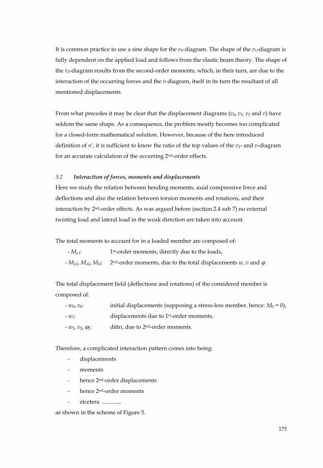
The total moments to account for in a loaded member are composed of:
- My1: 1st-order moments, directly due to the loads,
- My2, Mz2, Mt2: 2nd-order moments, due to the total displacements w, v and ϕ.
The total displacement field (deflections and rotations) of the considered member is
composed of:
- w0, v0: initial displacements (supposing a stress-less member, hence: M0 = 0),
- w1: displacements due to 1st-order moments,
- w2, v2, ϕ2: ditto, due to 2nd-order moments.
Therefore, a complicated interaction pattern comes into being:
- displacements
- moments
- hence 2nd-order displacements
- hence 2nd-order moments
- etcetera ............,
as shown in the scheme of Figure 5.
176
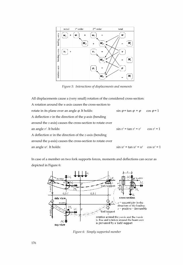
Figure 5: Interactions of displacements and moments
All displacements cause a (very small) rotation of the considered cross-section:
A rotation around the x-axis causes the cross-section to
rotate in its plane over an angle ϕ. It holds:
sin ϕ = tan ϕ = ϕ cos ϕ = 1
A deflection v in the direction of the y-axis (bending
around the z-axis) causes the cross-section to rotate over
an angle v'. It holds:
sin v' = tan v' = v' cos v' = 1
A deflection w in the direction of the z-axis (bending
around the y-axis) causes the cross-section to rotate over
an angle w'. It holds:
sin w' = tan w' = w' cos w' = 1
In case of a member on two fork supports forces, moments and deflections can occur as
depicted in Figure 6:
Figure 6: Simply supported member
177
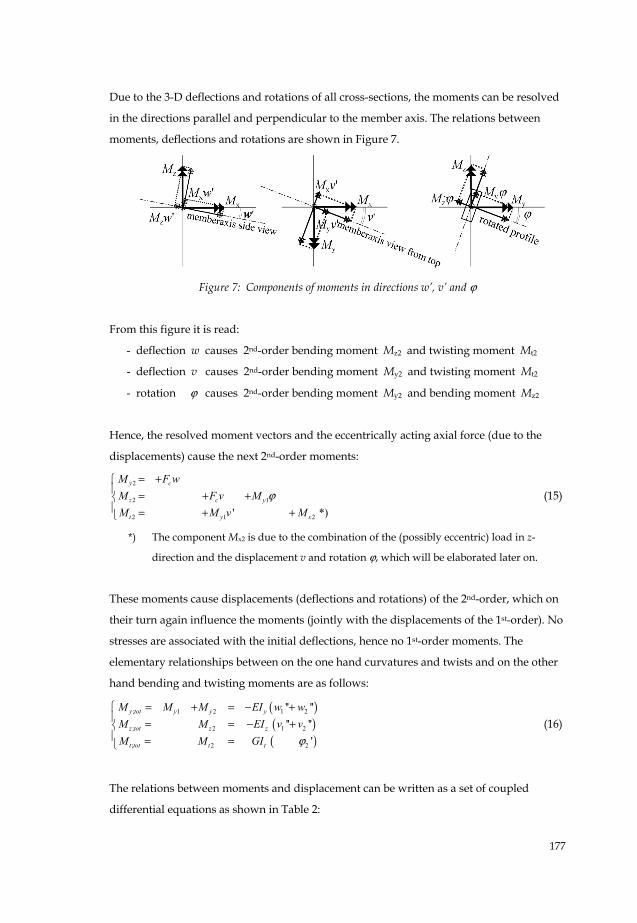
Due to the 3-D deflections and rotations of all cross-sections, the moments can be resolved
in the directions parallel and perpendicular to the member axis. The relations between
moments, deflections and rotations are shown in Figure 7.
Figure 7: Components of moments in directions w’, v’ and ϕ
From this figure it is read:
- deflection w causes 2nd-order bending moment Mz2 and twisting moment Mt2
- deflection v causes 2nd-order bending moment My2 and twisting moment Mt2
- rotation ϕ causes 2nd-order bending moment My2 and bending moment Mz2
Hence, the resolved moment vectors and the eccentrically acting axial force (due to the
displacements) cause the next 2nd-order moments:
2
2 1
2 1 2' *)
y c
z c y
t y x
M F wM F v MM M v M
ϕ= +⎧
⎪ = + +⎨⎪ = + +⎩
(15)
*) The component Mx2 is due to the combination of the (possibly eccentric) load in z-
direction and the displacement v and rotation ϕ, which will be elaborated later on.
These moments cause displacements (deflections and rotations) of the 2nd-order, which on
their turn again influence the moments (jointly with the displacements of the 1st-order). No
stresses are associated with the initial deflections, hence no 1st-order moments. The
elementary relationships between on the one hand curvatures and twists and on the other
hand bending and twisting moments are as follows:
( )( )( )
; 1 2 1 2
; 2 1 2
; 2 2
'' '''' ''
'
y tot y y y
z tot z z
t tot t t
M M M EI w wM M EI v vM M GI ϕ
⎧ = + = − +⎪ = = − +⎨⎪ = =⎩
(16)
The relations between moments and displacement can be written as a set of coupled
differential equations as shown in Table 2:

178
Table 2: Relations between moments and displacements
external moments internal moments
1st-order 2nd-order 1st-order 2nd-order
bending around y-axis My;tot = My1 +Fcw = -EIyw1" -EIyw2"
bending around z-axis Mz;tot = Fcv + My1ϕ = -EIzv2"
rotation around x-axis Mt;tot = My1v' + Mx2 = GItϕ2'
(17)
Now an important decision can be taken. The internal and external 1st-order terms are
completely equal and cancel-out. In solving the equations just the 2nd-order and total
displacements are kept:
2 2
2 1 2
2 1 2 2
''''
' '
y c y
z c y z
t y x t
M F w EI wM F v M EI vM M v M GI
ϕϕ
= = −⎧⎪ = + = −⎨⎪ = + =⎩
(18a)
These relationships may look simple, but it is practically impossible to find solutions
without help of numerical methods. These relationships will be the basis of the subsequent
elaboration in this article. The resting mutual relations between displacements and
moments have been remarkably reduced as is easily seen from a comparison of the new
scheme in Figure 8 with the preceding scheme in Figure 5.
Figure 8: Reduced interaction scheme of displacements and moments
It is concluded that the displacement w in the strong direction and its connected 2nd-order
effects have no influence on the flexural-torsional buckling and can (if wanted) be

179
calculated independently of v and ϕ. The displacement v in the weak direction and the
rotation ϕ keep dependent on each other, but are not influenced by displacements w, which
simplifies their calculation. Hence only the second and third equation of (18a) are relevant
and they can be written as:
2 1
1 2 2
'' 0' ' 0
z c y
y x t
EI v F v MM v M GI
ϕϕ
+ + =⎧⎪⎨ + − =⎪⎩
(18b)
3.3 Analysis methods
In spite of the simplification a pure mathematical closed-form solution of the derived
equations is only possible in a limited number of special load cases, such as the
combination of an axial compressive force Fc and a homogeneous bending moment My1
due to two equal opposite moments at the member ends.
Therefore, we look for a good approximation for the most occurring load cases in real
practice. The application of numerical methods, with aid of spread sheet programs, is an
effective instrument for the purpose. The interaction between the moments and
displacements will be analyzed by the execution of an iteration process, consisting of:
- Assumption of the shape of the displacement diagram,
- Calculation of the consequences thereof (moments),
- Calculation of the 2nd-order displacements due to the moments,
- Check the match of the resulting and assumed displacements,
- Repetition, if necessary, up to satisfactory match.
In the consulted literature critical loads (eigenvalues of the system) usually are derived
from differential equations. In fact, it is less interesting to choose the critical load as our
goal; one better can focus onto a reliable prediction of the structural behavior at increasing
load.
If one starts from an initial displacement, at first no stability problem does exist at all, but
the material strength is always decisive for the load bearing capacity of the member. It then
is important not to base the calculation on theoretical straight members, but to presuppose
a certain measure of imperfection as occurring in practical circumstances. Many codes of
practice provide relevant information for this initial deflection.
For a simple and unambiguous prediction of the flexural-torsional buckling behavior of
straight members three phases must be considered:
180
1. By way of an iteration method the value of the stability parameter *zn is calculated.
2. The influence of this quantity *zn to the amount of the 2nd-order effects is investigated.
3. Finally, the decisive stress to be expected is calculated and checked upon the applying
code of practice.
4 Iteration method – scheme steps
The investigated cases have been elaborated with the spread sheet program Quattro-Pro 9,
which was also used for the graphs of results. For the detailed set-up of the produced
spread sheets it is referred to [14].
Here the main lines of the process are discussed.
- The procedure starts with an estimate of the deflection v and its derivative v'.
- Then the twisting moment Mt2, the twist ϕ' and the rotation ϕ are computed from the
rotation equation.
- The 2nd-order moment Mz2 and curvature v2'' are computed from the bending equation.
- Two times integration yields the displacement v2.
- Finally, the quantity *zn is obtained as the ratio of v and 2v .
The match in shape of starting and final displacements can be checked automatically by
performing the computations iteratively. Each next iteration starts from the results of the
preceding one, hence the results become increasingly more accurate. The process can stop
if the results of successive iterations are sufficiently close. See Table 3 and Figure 9.
In the case of a constant moment all displacement components are sine-shaped (or cosine-
shaped) and in fact no iteration is needed because v and ϕ can be solved directly from the
governing differential equations.
On basis of the obtained value of *zn the 2nd-order effect can be derived, after which the
total stress can be determined and checked against the applying strength data.
181
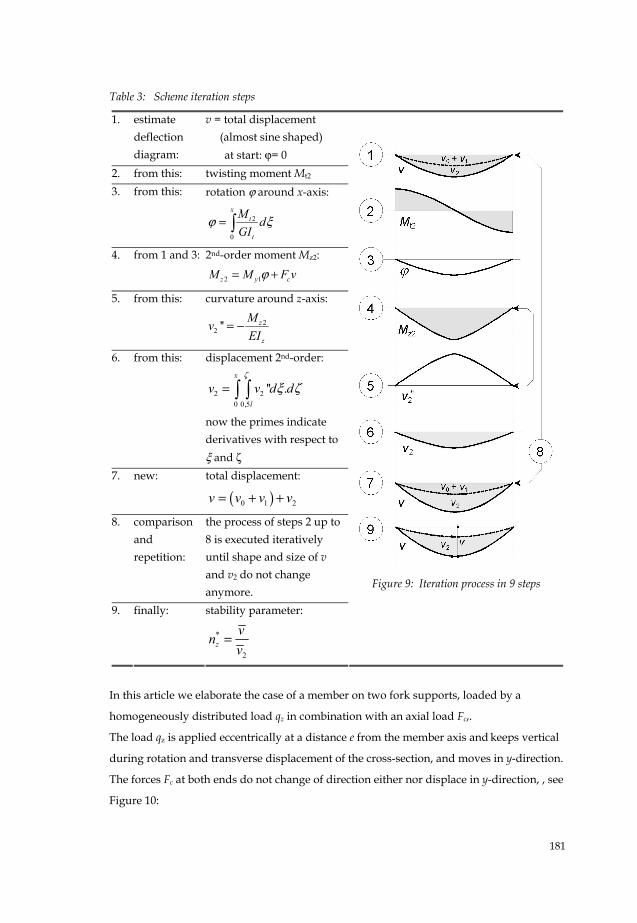
Table 3: Scheme iteration steps
1. estimate deflection diagram:
v = total displacement (almost sine shaped) at start: ϕ= 0
2. from this: twisting moment Mt2 3. from this: rotation ϕ around x-axis:
2
0
= ∫x
t
t
M dGI
ϕ ξ
4. from 1 and 3: 2nd-order moment Mz2:
2 1z y cM M F vϕ= +
5. from this: curvature around z-axis:
22 '' z
z
MvEI
= −
6. from this: displacement 2nd-order:
2 20 0,5
'' .= ∫ ∫x
l
v v d dζ
ξ ζ
now the primes indicate derivatives with respect to ξ and ζ
7. new: total displacement:
( )0 1 2v v v v= + +
8. comparison and repetition:
the process of steps 2 up to 8 is executed iteratively until shape and size of v and v2 do not change anymore.
9. finally: stability parameter:
*
2z
vnv
=
Figure 9: Iteration process in 9 steps
In this article we elaborate the case of a member on two fork supports, loaded by a
homogeneously distributed load qz in combination with an axial load Fc,.
The load qz is applied eccentrically at a distance e from the member axis and keeps vertical
during rotation and transverse displacement of the cross-section, and moves in y-direction.
The forces Fc at both ends do not change of direction either nor displace in y-direction, , see
Figure 10:
182
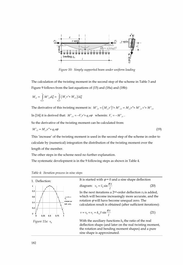
Figure 10: Simply supported beam under uniform loading
The calculation of the twisting moment in the second step of the scheme in Table 3 and
Figure 9 follows from the last equations of (15) and (18a) and (18b):
( )22 20,5 0,5
'' '+= =∫ ∫x x
y xt tl l
M v MM M d dξ ξ
The derivative of this twisting moment is: ( )2 1 2 1 1 2' ' ' ' '' ' ' 't y x y y xM M v M M v M v M= + = + +
In [14] it is derived that: 2' 'x z zM V v q eϕ= − + wherein: 1'z yV M= − .
So the derivative of the twisting moment can be calculated from:
2 1' ''t y zM M v q eϕ= + (19)
This ‘increase’ of the twisting moment is used in the second step of the scheme in order to
calculate by (numerical) integration the distribution of the twisting moment over the
length of the member.
The other steps in the scheme need no further explanation.
The systematic development is in the 9 following steps as shown in Table 4.
Table 4: Iteration process in nine steps
1. Deflection:
Figure 11a: 0v
It is started with ϕ = 0 and a sine shape deflection
diagram: 0 0 sin xv vl
π= (20)
In the next iterations a 2nd-order deflection v2 is added, which will become increasingly more accurate, and the rotation ϕ will have become unequal zero. The calculation result is obtained (after sufficient iterations):
0 2 1 sinaxv v v k vl
π= + = (21)
With the auxiliary functions kij the ratio of the real deflection shape (and later on the real twisting moment, the rotation and bending moment shapes) and a pure sine shape is approximated.

183
2. Twisting moment:
Figure 11b: tM
2tM is calculated by integration of M't2 - see (19).
( )20,5
''= +∫x
t yi zl
M M v q e dϕ ξ (22)
With the auxiliary functions kij this can be written as:
21
2 1 1 22 20,5
sinx
yt b y a
l
MM k M v k e d
l l lπ πξϕ ξ
⎛ ⎞= − +⎜ ⎟⎜ ⎟
⎝ ⎠∫ and results
in:
12 1 1 2 cosyt c y b
M xM k M v k el l lπ πϕ
π⎛ ⎞
= −⎜ ⎟⎜ ⎟⎝ ⎠
(23)
3. Rotation of the cross-section:
Figure 11c: ϕ
ϕ can be calculated by integration:
1 1 2 12
0 0
' sin−
= = =∫ ∫x x
d y c yt
t t
k M v k M eM xd dGI GI l
ϕ πϕ ϕ ξ ξ (24)
with top value at: x = 0,5l:
1 1 2 1 1 1
2 1
d y c y d y
t t c y
k M v k M e k M vGI GI k M e
ϕϕ
−= =
+ (25)
In Figure 11c it can be seen that the rotation shape accurately agrees with a pure sine shape.
4. 2nd-order moment:
Figure 11d: 2zM
Mz2 is obtained by: resolving of the moment My1, so: My1ϕ
axial force × deflection, so: Fcv
( )2
1 12 1 1
2 1
sine yz y c a c
t c y
k M xM M F v k F vGI k M e l
πϕ⎛ ⎞⎜ ⎟= + = +⎜ ⎟+⎝ ⎠
(26)
In Figure 11d the divergences are showed between the 2nd-order moment shape and a pure sine shape that has to be taken into account.
5. Curvature around the z-axis:
The general relation between moment and curvature is:
( )2
1 122 1
2 1
'' sine yza c
z t c y z
k MM v xv k FEI GI k M e EI l
π⎛ ⎞⎜ ⎟= − = − +⎜ ⎟+⎝ ⎠
(27)
6. 2nd-order deflection:
v2 is obtained from two times integration of the curvature:
( )22
1 12 2 1 2
2 10 0,5
'' . sin⎛ ⎞⎜ ⎟= = +⎜ ⎟+⎝ ⎠
∫ ∫x
f ya c
t d y zl
k M l xv v d d k F vGI k M e EI l
ζ πξ ζπ

184
7. The new deflection:
Figure 11e: v
Because in the analyzed case k1a ≈ 1 and the other auxiliary functions finally can be written as constant factors : k1 respectively k2, the 2nd-order deflection becomes:
( )22
1 12 2
2 1
sinyc
t y z
k M l xv F vGI k M e EI l
ππ
⎛ ⎞⎜ ⎟= +⎜ ⎟+⎝ ⎠
(28)
Finally the total deflection is: 0 2v v v= +
8. Check on similarity: In spite of the in step 4 (Figure 11d) founded divergences
between the 2nd-order moment shape and a pure sine
shape it appears that (after two times integration) the
final deflection shape closely agrees with the supposed
deflection as started in step 1. Compare the Figures 11a
and 11e.
9. The wanted quantity of the stability parameter *
zn :
The ratio of 2v and v is now most easily written in reciprocal form:
( )22
1 12* 2
2 1
1 yc
z t y z
k Mv lFn v GI k M e EIπ
⎛ ⎞⎜ ⎟= = +⎜ ⎟+⎝ ⎠
(29)
From (14) it follows that the amplification factor runs to infinity for *zn =1. The situation
then has become critical. We will consider three cases for which *zn = 1 applies:
a. If the member is just loaded by an axial force Fc , a critical state is obtained, for which: 2
; 2z
c crEIFl
π= (30)
In this way the well-known Euler’s buckling formula is derived from the displacements. It
can be written:
;c cr E zF F= (31)
b. If the member is just loaded by a constant moment My the factor k1 = 1 and a critical
state is obtained, for which: 2
21; 2
z ty cr E z t
EI GIM F GIl
π= = or:
185
1;y cr E z tM F GI= (32)
In the classical literature this is called the theoretical elastic flexural-torsional buckling
moment, which often is written as:
cr z tM EI GIlπ= (33)
c. At a combination of a constant bending moment and an axial force the stability
parameter *zn can most easily be written with two (serially chained) components:
* * *
1 1 1
z zM zFn n n= + (34)
where:
2*
21
crzM
y
MnM
= and: * EzzF
c
FnF
= (35) and (36)
If the moment will vary along the member and the load is applied eccentrically, the
equations (34), (35) and (36) are still valid, however *zMn becomes:
* * *zM zMcr zMen n n= + (37)
where: 2
*
1 1
crzMcr
y
Mnk M
⎛ ⎞= ⎜ ⎟⎜ ⎟⎝ ⎠
and: ( )2 1*
2
1 1
y EzzMe
y
k M eFn
k M= or: *
2 1'Ez
zMey
eFnk M
= (38a), (38b), (38c)
where k1 and k2 are dimensionless constants.
In [14] several member types and load cases have been investigated, resulting into
adequate values for these constants, listed in Table 5.
Table 5: Constants for the investigated member types and loads
Member type Load k1 k2 k’2
two fork supports constant moment My1
homogeneously distributed load qz
concentrated mid-span load Fz
1
0,87
0,73
1
0,81
0,87
1
0,96
0,61
cantilever constant moment My1 (e = 0)
homogeneously distributed load qz
concentrated end-of-span load Fz
1
0.24
0.41
1
0.65
0.57
1
0.09
0.29

186
It is concluded that the influences of the loads qz and Fz (responsible for the moments 1yM )
and the eccentricity e act parallel, however the joint interaction of the compressive force Fc
on the one hand and qz, Fz and e on the other hand are chained serially. This is
schematically visualized in Figure 12.
Figure 12: Scheme of serial and parallel interaction
Also combinations of different types of load, like moments in rigid supports and several
concentrated loads, are investigated by iteration processes. In those cases it was observed
that they can be accounted for by way of superposition using (38a) and (38b):
in the denominators of (38a) and (38b):
1 1 1;case1 1;case1 1;case2 1;case2 .....y y yk M k M k M= + + (39a)
in the numerator of (38b):
( )2 1 2;case1 1;case1 case1 2;case2 1;case2 case2.....y Ez y y Ezk M eF k M e k M e F= + (39b)
Herein the eccentricity for the member deadweight is zero. The signs in all terms must be
well chosen. Negative support moments have (in case of dominantly positive span
moments) favorable effect on the stability, therefore they are subtracted. If so wished also
values of the factors k may be calculated by interpolation in proportion to the loads. In this
way *zn can be determined for most practical cases in a surveyable and rather simple way.
5 Check on strength and stiffness
For the purpose of applications in design practice checking criteria are mostly extracted
from applying codes of practice. Because these codes are changed on a regular basis, we
will refer to them as few as possible and, in stead, develop an autonomous calculation
method for compressive-flexural-torsional buckling of members.
Having started from an initial deflection v0, the check is based on general principle for
strength and stiffness, a simply to formulate, and applicable to structures in all kind of
materials.

187
5.1 Checking procedure
We distinguish two limit states when judging stability, strength and stiffness of structures:
- ULS (ultimate limit state) for strength,
- SLS (serviceability limit state) for normative displacement.
The loads to account for in ULS (by way of load factors) are larger than in SLS, and the
modulus of elasticity (dependent on the material) is sometimes smaller. As a consequence,
the SLS-values of *zn are always larger than the ULS-values. In both limit states we can
calculate the displacements with the same method.
The idea of the checking procedure is simple:
- ULS: it is investigated in which cross-section the normative design stress occurs, after
which this stress is compared to the strength of the material (unity-check).
- SLS: it is investigated where the normative deflection occurs, after which this
deflection is compared to the permissible one according to the applying
requirements.
The necessary components are:
- external forces and moment: follow from equilibrium,
- geometric data: follow from beam theory,
- buckling stress: follows from Euler’s formula,
- critical flexural-torsional moment: follows from lateral stiffness and torsion
stiffness,
- initial eccentricity: follows from the nature of the material or from
the code at stake,
- the quantity n* : follows from the derived formulas in section 4,
- 2nd-order moments: follow from the derived formulas in section 5.
5.2 Check on strength in the ULS
In case of the here considered members, mainly bending stresses and (to a smaller degree)
compressive stresses are relevant. Because they all act in axial direction of the member,
they can simply be superimposed, as long as Hooke’s law is applicable. See Figure 13.

188
Figure 13: Superposition of stresses
In the normative position of the cross-section the ULS-strength can be checked with aid of:
1yc z
u uy uz
MF MF M M
+ + ≤ (40)
The three quantities in the denominators are the respective ultimate design quantities.
As a rule, the moment zM is a 2nd-order moment. In general it holds:
2 2 ''z zM EI v= − (41)
Hence from: (27) and (28) zM can be short written as:
22
2 223 3
z Ezz
EI F vM vk l k
π= = (42)
where k3 is a dimensionless factor, dependent on the shape of the M-diagram.
As commonly known, the shape and area of the moment diagram provides information on
the size and the distribution of the deflections, and this holds true in the reversed direction
as well. In case of a constant moment My1 and/or a preponderant axial force (and so a sine
shape of the v2 diagram) the factor is: k3 = 1. If the moment My1 varies along the member,
the factor has been studied for several load cases and support conditions in [14].
It appears that for members on two fork supports the value of k3 is (practically) the same as
the earlier calculated factor k1 and that for cantilevers k3 can be approximated with:
3 1 20,8k k k≅ + .
The calculation of 2zM starts with the determination of *zn according to (34).

189
The relations between the initial deflection, the 2nd-order deflections and the total
deflection result from (12) and (13):
02 * * 1z z
v vvn n
= =−
(43)
The value of 0v often can be extracted from the applying code of practice, and is – mostly -
expressed in relation to the member length l (order of magnitude 1/1000 until 1/300).
So 2zM can be written:
02 *
3 1Ez
zz
F vMk n
=−
(44)
This result is substituted in the checking formula (40).
This result is fine for rectangular cross-sections, but in members with an I-shaped cross-
section one must account for an additional term. Because of the warping component Mtw in
the torsion moment, flange bending moments occur. In members on two fork supports the
maximum value occurs at mid-span, and to calculate the stresses we must use the section
modulus Wflz =0,5 Wz. Because the bending moments My1 en Mz2 are maximal at the same
position as well, we best can consider Mz2;fl to be a ‘supplement’ to Mz2.
In [14] it is derived for a member on two fork supports: *
2;*
2 14z fl Ez z
z y zM
M F h nM M n
= (45)
In absence of an axial compressive force this formula can be simplified to:
2;
2 14z fl Ez
z y
M F hM M
= (46)
In total the moment in the middle of the member span can exist of two components:
1. A 2nd-order moment: 02 *
3 1Ez
zz
F vMk n
=−
see (44)
2. An additional 2nd-order component for I-sections,
due to flange bending:
(with section modulus Wflz =0,5 Wz)
*
2; 2*14
Ez zz fl z
y zM
F h nM MM n
= see (45)
After all necessary components have been calculated, they are substituted in the checking
formula (40).
Although it is a temptation to combine the foregoing formulas, we purposely abstain from
that for easy reference.

190
5.3 Check on stiffness in the SLS
Stresses in the serviceability limit state are lower than in the ultimate limit state, 2nd-order
effects are (much) smaller and sometimes the elasticity modulus is larger (in case of timber,
for instance). Yet, the same formula’s can be used.
The admissible deflection can be extracted from:
- applying codes of practice,
- additional requirements, due to the nature of the structure or special circumstances.
Mostly, these requirements regard the deflections in the direction of the load. It can be
checked if the requirements are met with aid of *yn through a procedure in three steps:
1. Calculation of the stability parameter *yn :
*
1 c
y Ey
Fn F
= (47)
(which is influenced exclusively by an axial compressive force, and not by flexural-torsional effects)
1. Calculation of the normative deflection (in the middle of the member): ( )
*
0 1 * 1y
y
nw w w
n= +
− + creep effects (48)
3. Finally, checking by: w w≤ allowable = i.e. 0.004 l (49)
Dependent on the application, one could also distinguish between so called additional
deflection (for variable load only) and total deflection (for both permanent and
variable load).
A possible check on the deflections in the weak direction can be executed with the same
calculation procedure in three steps:
1. Calculation of the quantity *zn :
* * *
1 1 1
z zM zFn n n= + see (34)
2. Calculation of the normative deflection: *
0 * 1z
z
nv vn
=−
+ creep effects (50)
3. Finally, checking by: v v≤ allowable = i.e. 0.004 l (51)
Also here again, possibly distinguishing between the additional and total deflection.
5.4 Sensitivity and accuracy
If structures become so slender that stresses due to 2nd-order effects start to be dominant,
the state can become seriously dangerous. This is the case for values n* = 2 à 3 or lower. As
follows from (13) and all formula’s derived thereof, the final deflections and stresses will

191
increase disproportionately at further increasing (variable) load and (as a consequence
thereof) smaller values of n*.
The determination of the stability parameters *zn and/or *
yn provides good information
about the 2nd-order effects and, therefore, is a valuable contribution to the design and
construction of reliable structures.
6. Applications
The strength and stiffness of laterally supported members can be checked according to a
conveniently-arranged procedure:
1. Collecting of data on the geometry of the considered member and the loads.
2. Choice of (reduction) factors, dependent on member type and load.
3. Determination of the needed components, dependent on member type and load.
4. Check if requirements for ULS and SLS are met.
6.1 Overview
In the overview below the procedures and formula’s, derived in this article, are collected.
For a more complete overview for other cases like members continuing over several
supports and cantilever members, it is referred to [14].
a. Collection of data
items notations explanation
normative moment: 1yM in the middle of the member.
0 0vv k l=
initial deflection:
in the weak direction
also in the strong direction:
(if necessary)
0 0w v=
to be extracted from material
properties and/or applying
codes of practice. Order of
magnitude:
kv0 = 1/1000 à 1/300.
properties of the cross-section: A b h Iy Iz Itor Wy Wz
etc.
to be extracted from structural
mechanics formula’s or tables.
material properties: E G fc fm etc. dependent on material.
eccentricity of the load: e positive in direction of load.

192
b. Choice of constants, depending on member type and load:
member type loaded by k1 k2 k’2 k3 member on two fork supports:
constant moment (e =0) homogeneously distributed load qz concentrated load at mid-span Fz
1 0.88 0.73
1 0.81 0.87
1 0.96 0.61
1 0.88 0.73
cantilever: constant moment My1 (e = 0) homogeneously distributed load qz concentrated end-of-span load Fz
1 0.24 0.41
1 0.65 0.57
1 0.09 0.29
1 0.79 0.85
c. Involved quantities and formulas:
Euler buckling load:2
2z
EzEIFl
π= ditto in strong direction (if wanted)
2
2y
Ey
EIF
lπ
=
torsion stiffness:: ( )1t tor twGI GI C= +
for rectangular cross-sections: for I-sections:
0twC =
2 2
24z
twtor
EI hCGI l
π=
critical flexural-torsional moment:
cr Ez tM F GI=
components related to moment:
* * *zM zMcr zMen n n= +
2
*
1 1
crzMcr
y
Mnk M
⎛ ⎞= ⎜ ⎟⎜ ⎟⎝ ⎠
* 22 '
1 1 2 1
Ez EzzMe
y y
k eF eFnk M k M
= =
stability parameter: * * *
1 1 1
z zM zFn n n= +
component related to axial force:
* EzzF
c
FnF
=
combination of different loading types (substitute with correct sign)
1 1 1; 1;y i y ik M k M=∑
2 2 2; 2;y i y ik M e k M e=∑
i = case 1, case 2, etc. respectively
2nd-order moment:
; 2 2;2z tot z z flM M M= +
bending moment: flange bending moment:
(for I-sections only) section modulus Wflz = 0,5Wz)
( )0
2 *3 1
Ezz
z
F vMk n
=−
*
2; 2*14
Ez zz fl z
y zM
F h nM MM n
=
stability parameter (if wanted) in 'strong' direction:
* * Eyy yF
c
Fn n
F= =

193
d. Checking
ULS strength: calculation for ULS-load
1 ; 1y z totc
u uy uz
M MFF M M
+ + ≤
deflection: calculation for SLS-load
in the 'strong' direction: ( )
*
0 1 * 1y
y
nw w w
n= +
− where: *
1 c
y Ey
Fn F
=
w w≤ allowable = i.e. 0.004 l
SLS
possibly distinguishing between additional and total deflection
if wanted in the 'weak' direction:
*
0 * 1z
z
nv vn
=−
where: * * *
1 1 1
z zM zFn n n= +
v v≤ allowable = i.e. 0.004 l 6.2 Calculation example
To illustrate the procedure a calculation example will be shown. We consider a steel
member on two fork supports under a homogenously distributed load and axial
compressive force, see Figure 14.
The calculation exists of two parts:
- one that has to be executed regardless of the chosen method, whatsoever, and
- one that is specifically focused to the method developed in this article.
Figure 14 I-beam under representative uniform loading
6.2.1 a . Data
member length:
section HE600A:
initial deflection:
l = 10 [m]
h = 0.590 and b = 0.300 ,,
0 10 / 500 0.020v = = ,,
Section data, extracted from
tables for steel sections:

194
loads:
deadweight:
variable, distributed:
compressive force:
in the SLS:
qw = 2
qz = 28
Fc = 200
in the ULS:
2.4 [kN/m]
42 [kN/m]
300 [kN]
eccentricity of load e = - 0.590/2 = - 0.295 [m]
(here for variable load only)
material data: E = 210×106 [kN/m2]
G = 0.4E = 84×106 ,,
A = 22646 × 10-6 [m2]
Iy = 1412 × 10-6 [m4]
Iz = 113 × 10-6 [m4]
Itor = 3.5 × 10⁻⁶ [m4]
Iw = 9 × 10⁻⁶ [m6]
Wy = 4787 × 10-6 [m3]
Wz = 751 × 10-6 [m3]
ULS total stress: tot yf f≤ = 0.235×10⁶ [kN/m2] checking criteria:
SLS total deflection:
additional deflection: 0 1 2
0 2
0.004w w w w
lv v v
− = + ⎤≤ =⎥− = ⎦
0.0040 10 0.040 [m]= × =
b. Elaboration
SLS ( ) 21;
1 2.0 28 10 25 350 3758y repM = + = + =
280.295 0.2752 30
e = − × = −+
[kNm]
[m]
design values
moments and
eccentricities :
ULS ( ) 21;
1 2.4 42 10 30 525 5558y repM = + = + =
420.295 0.2792.4 42
e = − × = −+
[kNm]
[m]
ultimate normal
force
and moments:
Fu = 0.235 × 22646 = 5322
Myu = 0.235 × 4787 = 1125
Mzu = 0.235 × 751 = 176
[kN]
[kNm
[kNm]
Euler buckling
load:
torsion stiffness:
warping stiffness:
effective torsion stiffness: critical flexural-torsional moment:
2 6 6
2210 10 113 10 2342
10EzFπ −× ⋅ × ⋅= =
6 684 10 3.5 10 294torGI −= ⋅ × ⋅ =
210 9 1890wEI = × =
2
21890 0.63
10 294twCπ ×= =
×
( )294 1 0.63 480tGI = + =
2342 480 1060= × =crM
[kN]
[kNm2]
[kNm4]
[--]
[kNm2]
[kNm]
So far the calculation does not differ from usual approaches in codes.
195
Now it is followed by a part for the calculation and checking of the strength and stiffness
conform the method developed in this article. 6.2.2 a . ULS - strength factors: k1 = 0.88 k2 = 0.81 k’2 = 0.96 (from Table 5)
stability parameter *zn 2
*
*
1060 0.275 2342 3.50.88 555 0.96 555
2342 7.830
zM
zF
n
n
⎡ − ×⎛ ⎞= + =⎢ ⎜ ⎟× ×⎝ ⎠⎢⎢
= =⎢⎢⎣
alternative:
( )( )
2
* 2
*
0.88 5551 11060 0 0.81 525 0.295 2342 3.5
1 300 12342 7.8
zM
zF
n
n
⎡ ×= =⎢
+ − × × ×⎢⎢⎢ = =⎢⎣
*
1 1 1 13.5 7.8 2.4zn
= + =
comment, alarming function: This size of the stability parameter *zn definitely requires
reconsidering the design critically, because the 2nd-order amplification factor of
2.4 1.712.4 1
=−
is rather large.
2nd-order bending moment: ( )2
2342 0,020 380.88 2.4 1zM
×= =−
kNm]
flange bending moment: 2;
2342 0.590 2.4 38 164 555 3.5z flM ×= × × =
× [kNm]
Seldom attention is paid to the flange bending moment Mz2;fl, that roughly is related to the
2nd-order moment Mz2 by the warping factor Ctw . This moment must be carried per flange,
so half the section modulus in the weak direction is used.
check: 300 555 38 16 0.06 0.50 0.21 0.18 0.95 15322 1125 176 0.5 176
+ + + = + + + = <×
comment: the extra stress due to the 2nd-order contribution is: 0,21 0,18 70%0,06 0,50
+⇒
+
which agrees well with the amplification factor 1.67, found before.
Indeed, the checking result 0.95 <1 is satisfactory, but the size of *zn yet is a reason to be
wakeful. The safety may seem 5%, however this is very relative, for an increase in load
would yield a disproportionate raise of the checking value 0.95. An increase of the load of
5% makes the checking value 1.04, which is an increase of 9%, almost the double.

196
For reasons of illustration it is investigated in which way the checking value develops at
increasing load. The result is shown in Figure 15.
Figure 15: Increasing check result for increasing loading
The axes indicate:
- horizontal: ratio of the load and the design load
- vertical: the checking value.
The circled point marks the result of the preceding calculation with checking value 0.95.
From the graph the following conclusions are drawn:
- A safe result is found for small loads.
- The checking value grows progressively for increasing loads.
- Therefore, thinking in terms of a linear relation is dangerous.
b. SLS - 1. stiffness in the strong direction
The deflections can be calculated according section 5.3
First determination of Euler buckling force: and deflection 1st-order:
2 6 6
2
210 10 1412 10 2926510EyF
π −× ⋅ × ⋅= =
2
1 6 6
5 375 10 0.01348 210 10 1412 10
w −
× ×= =× ⋅ × ⋅
[kN] [m]
stability parameter *yn : * 29265 146
200yn = =
normative deflection: ( ) 1460.020 0.013 0.033146 1
w = + =−
[m]
check: 0 0.033 0.020 0.013 0.040w w− = − = ≤ [m]

197
2. stiffness in the weak direction
This calculation will not be often necessary, but can be executed (if wanted) with:
stability parameter *zn :
2*
*
1060 0.279 2342 8.50.88 375 0.96 375
2342 11.7200
zM
zF
n
n
⎡ − ×⎛ ⎞= + =⎢ ⎜ ⎟× ×⎝ ⎠⎢⎢
= =⎢⎢⎣
alternative:
( )( )
2
* 2
*
0.88 3751 11060 0 0.81 350 0.295 2342 8.5
1 200 12342 11.7
zM
zF
n
n
⎡ ×= =⎢
+ − × × ×⎢⎢⎢ = =⎢⎣
*
1 1 1 18.5 11.7 4.9zn
= + =
normative deflection: 4.90.020 0.025
4.9 1v = × =
− [m]
check: 0 0.025 0.020 0.005 0.040v v− = − = ≤ [m]
7 Conclusions and recommendations
7.1 Conclusions
1. The developed stability parameter n* can have a very important 'alarming function' in
the assessment of the stability behavior of members. Therefore, it is strongly
recommended to pay careful attention to the size of *zn , and take care that it does not
become smaller than 2 à 3.
2. It’s true, this role of n* is not completely unknown, but was not given a place in
regulations on flexural-torsional buckling in the consulted building codes and
literature. At increasing load approaching the critical value, sudden loss of stability
(and failure of the structure) may occur. Clearly, the 'unsuspecting' application of
checking rules which do not show this is dangerous.

198
3. A method for compressive-flexural-torsional buckling has been derived, applicable to
all existing building materials in structural engineering for which plasticity
considerations do not influence the beam-column buckling load to a substantial
extent.
4. Essentially the calculations can be done in a short time using a pocket calculator,
without the use of other utilities.
5. It has been deliberately chosen not to elaborate the derived formulas too far, in order
to preserve a clear view on the cohesion and procedure.
7.2 Recommendations
1. It is desirable and possible to apply to all building materials the same calculation
system for the checking regulations regarding stability, stiffness and strength of
members, which are loaded in bending and compression.
2. Apart of the cases mentioned in [14], larger applications should be investigated which
adaptations are necessary for:
- other than straight, prismatic members (i.e. curved and/or tapered members),
members with other cross-section shapes, sloped frames and also cracked
reinforced concrete cross-sections.
- materials for which the theory of elasticity does not apply, for instance plastic
behavior.
References
[1] Timoshenko, S. Theory of elastic stability, (1st edition) New York, 1936.
[2] Timoshenko, S. and Geere, J.M., Theory of elastic stability, New York, 1961.
[3] Bleich, F., Buckling Strength of Metal Structures, McGraw-Hill, 1952.
[4] Chen, W.F. and Atsuta, T., Theory of beam-columns, vol. 2. Space behavior and design,
New York, 1977.
[5] Bazant, Z. P. and Cedolin, L., Stability of Structures: Elastic, Inelastic Fracture and
Damage Theories, Oxford University Press, New York, 1991
[6] Trahair, N.S. Flexural-torsional buckling of structures, London, 1993.

199
[7] Brüninghoff, H., Spannungen und Stabilität bei quergestützten Brettschichtträgern,
Karlsruhe, 1972.
[8] Blass, H.J., Tragfähigkeit von Druckstäben aus Brettschichtholz unter Berücksichtigung
streuender Einflussgrössen, Karlsruhe, 1987.
[9] Pauli, W., Versuche zur Kippstabilität an praxisgerechten Fertigteilträgern aus Stahlbeton
und Spannbeton, Darmstadt, 1990.
[10] Lohse, G., Kippen, Düsseldorf, 1997.
[11] Eggen, T.E., Buckling and geometrical nonlinear beam-type analyses of timber structures,
Trondheim, 2000.
[12] Van der Put, T.C.A.M., Stability of beams (background of Dutch code TGB) Chapter
KH 10 in PAO Continuing Education Course "Structures in timber", Delft 1992. (Title of
the chapter is in Dutch: Stabiliteit van liggers (achtergrond TGB) in Cursus
'Constructies in hout”. Text of the chapter is in English).
[13] Erp, G.M. van, Advanced buckling analyses of beams with arbitrary cross-sections,
Eindhoven, 1989.
[14] Raven, W.J., New vision on flexural-torsional buckling. Stability and strength of structural
members (in Dutch: Nieuwe blik op kip en knik, Stabiliteit en sterkte van staven),
doctoral thesis, Delft 2006. To download from TU-Delft library:
http://repository.tudelft.nl/file/204111/173135
[15] TGB 1990, NEN 6700, and successive supplements, Dutch building code.
Appendix
Notations In this article the following symbols are used: Geometry of member l length [m] A area of cross-section [m2] Afl area of flange [m2] b width of cross-section [m] h depth of cross-section [m] e eccentricity of load in z-direction [m] x,y,z variables along the coordinate axes [m] ξ, ζ auxiliary variables (along the x-axis) [m] Static properties Iy, Iz second moment of cross-section for bending [m4] corresponding with My and Mz Itor second moment for torsion at no restrained warping [m4]

200
It idem, restrained warping included [m4] Iw bimoment of cross-section [m6] W section modulus for bending [m3] Material properties E modulus of elasticity [N/m2] G shear modulus [N/m2] fc compressive strength [N/m2] fm strength in bending [N/m2] Stiffness and strength Ctw dimensionless quantity for the influence of the warping stiffness [--] FE Euler buckling load [N] Fu ultimate compressive strength Fc [N] Mcr critical moment M at flexural-torsional buckling [Nm] Mu ultimate moment M at bending [Nm] n stability parameter (applied in classical theory of Eulerian buckling) [--] n* stability parameter (newly introduced in this article) [--] Loads, moments and shear forces qz load per unit length (in z-direction) [N/m] F concentrated load [N] Fc axial compressive force in x-direction [N] Mx twisting moment in cross-section around the x-axis [Nm] My bending moment in cross-section around the y-axis [Nm] Mz bending moment in cross-section around the z-axis [Nm] Mt twisting moment in cross-section around member axis [Nm] V shear force in cross-section [N] Stresses σc compressive stress [N/m2] σm bending stress [N/m2] τ shear stress [N/m2] Displacements w displacement in z-direction [m] v displacement in y-direction [m] v0 initial displacement in y-direction [m] v1 first-order displacement in y-direction [m] v2 second-order displacement in y-direction [m] ϕ rotation of a member cross-section around the x-axis [rad] ϕ' torsion = rotation per unit length [rad/m] Auxiliary quantities k constant, factor, coefficient [--] ki. reduction factor ( i = 1, 2, 3, ..... ) [--] f in general: a dash on top of a symbol indicates the maximum value of the
considered function in case of moments, stresses and displacements.


![Determination of the Shear Buckling Load of a Large ......energy theory for flexural torsional buckling of an open channel beam. Many other recent papers [7–11] have described theoretical](https://img.dokumen.tips/doc/110x75/6044cf821770275156120b4c/determination-of-the-shear-buckling-load-of-a-large-energy-theory-for-flexural.jpg)