Embed Size (px)
Citation preview

EL MONTE AIRPORTMaster Plan Report
EI Mantei California
Prepared forthe
County ofLos Angeles
June 1995

COUNTY OF LOS ANGELES
Board of Supervisors
Gloria Molina, Chair of the BoardYvonne Brathwaite BurkeZev Yaroslavsky
Deane Dana
Michael D. Antonovich
Aviation Commission
Annette M. "Nini" Cuter, Chairman
James F. Burton, Vice ChairmanAngelo R. Cardono, SecretaryClyde C. BaileyLester E. BensonDonald J. BohanaConstnce Lynch KoehlerRoger L. PersonsClinton Simmons
James M. Woos, Sr.
Staff
Ted A. Gustin, Chief, Aviation Division
James H. Abing, Project Manager
EFFECTIVE APRIL i, 1991, EL MONTE AIRPORT IS OPERATED UNDER THE TERMS OF AMANAGEMENT SERVICES AGREEMENT BETEEN THE COUNTY OF LOS ANGELES
(OWNER) AND CO MARCO , INC. (CONTRACTOR).
The preparaion of this document wa financed in pa through a planning grat from the Federal AviationAdministration (FAA) as provided under Section 505 of the Airport and Airwy Improvement Act asamended. The contents of this report reflec the views of Hodges & Shut, who is responsible for the factand accuracy of the data presented herein. The contents do not necessarily reflect the offcial views of theFAA. Acceptance of this report by the FAA does not in any way constitute a commitnt on the part of the
United States to participate in any development depicted herein, nor does it indicate that the proposeddevelopment is environmentally acceptable in accordance wit Public Laws 91-190, 91-258, and/or 90-495.

Table of Contents
1 IntroductionSTUDY BACKGROUND
Contents of the Plan .................................................. .
............ .......................................
2 SummaryOVERVIEW .............................................................
PLAN DRAWiNGS.......................................................BACKGROUND AND INVENTORY ..........................................AIRPORT ROLE AND ACTIVITY .............................................
Airport Role .........................................................
.. Historical Airport Activity ...............................................
Activity Forecasts .....................................................
Capacity Analyses . . . . . . . . . . . . . . . . . . . . . . . . . . . . . . . . . . . . . . . . . . . . . . . . . . . . .PROPOSED AIRFIELD IMPROVEMENTS . . . . . . . . . . . . . . . . . . . . . . . . . . . . . . . . . . . . . . .
Basic Design Factors ............................ . . . . . . . . . . . . . . . . . . . . . . ~Runway Design . . . . . . . . . . . . . . . . . . . . . . . . . . . . . . . . . . . . . . . . . . . . . . . . . . . . . . .Other Airfeld Design Issues .............................................
BUILDING AREA DEVELOPMENT. . . . . . . . . . . . . . . . . . . . . . . . . . . . . . . . . . . . . . . . . . . .Design Considerations .................................................
Proposed Building Area Improvements. . . . . . . . . . . . . . . . . . . . . . . . . . . . . . . . . . . . .LAND USE AND ENVIRONMENTAL ISSUES. . . . . . . . . . . . . . . . . . . . . . . . . . . . . . . . . . . .
Compatibility Concerns . . . . . . . . . . . . . . . . . . . . . . . . . . . . . . . . . . . . . . . . . . . . . . . . .Land Use Compatibility Measures . . . . . . . . . . . . . . . . . . . . . . . . . . . . . . . . . . . . . . . . .Airport Facility and Operational Measures ..................................
Environmental Issues . . . . . . . . . . . . . . . . . . . . . . . . . . . . . . . . . . . . . . . . . . . . . . . . . . .FINANCIAL AND IMPLEMENTATION ISSUES. . . . . . . . . . . . . . . . . . . . . . . . . . . . . . . . . . .
Capital Improvement Program ...........................................
Financial Projection . . . . . .. . . . . . . . . . . . . . . . . . . . . . . . . . . . . . . . . . . . . . . . . . . . . .Financial Recommendations .............................................
Master Plan Adoption ..................................................
Implementation . . . . . . . . . . . . . . . . . . . . . . . . . . . . . . . . . . . . . . . . . . . . . . . . . . . . . . .
3 Background and InventoryEL MONTE AIRPORT .....................................................
Location and Environs . . . . . . . . . . . . . . . . . . . . . . . . . . . . . . . . . . . . . . . . . . . . . . . . . .Airport Development ..................................................
Airport Management and Operations ......................................
AERONAUTICAL SETTING .................................................
COMMUNITY PROFILE ...................................................
PREVIOUS AIRPORT PLANS AND STUDIES ...... . . . . . . . . . . . . . . . . . . . . . . . . . . . . . .AIRPORT USER QUESTIONNAIRE RESULTS ....... . . . . . . . . . . . . . . . . . . . . . . . . . . . . .
1-1
1-2
2-12-22-32-42-42-52-52-62-62-62-72-82-92-9
2-102-112-112-122-132-142-142-142-152-162-162-17
3-13-13-63-83-9
3-143-143-15

Table of Contents
4 Airport Role and ActivityAIRPORT ROLE . . . . . . . . . . . . . . . . . . . . . . . . . . . . . . . . . . . . . . . . . . . . . . . . . . . . . . . . . .
Present .............................................................
Future ..............................................................
HISTORICAL AIRPORT ACTIVITY ............................................
Based Aircraft ........................................................
Aircraft Operations ....................................................
Distribution of Activity .................................................
Fuel Flowage . . . . . . . . . . . . . . . . . . . . . . . . . . . . . . . . . . . . . . . . . . . . . . . . . . . . . . . . .BASED AIRCRAFT DEMAND FORECASTS .....................................
National and Regional Demand Factors ....................................
Demand Factors Specific to EI Monte Airport . . . . . . . . . . . . . . . . . . . . . . . . . . . . . . . .Other Based Aircraft Demand Forecasts ....................................
Based Aircraft Demand Conclusions ................... . . . . . . . . . . . . . . . . . . . .TRNSIENT AIRCRAFT PARKING DEMAND. . . . . . . . . . . . . . . . . . . . . . . . . . . . . . . . . . . .AIRCRAFT OPERATIONS FORECASTS ........................................
Forecast Influences ....................................................
National and Regional Forecasts ....................... . . . . . . . . . . . . . . . . . . .Annual Operations Demand Conclusions ...................................
CAPACITY ANALYSES . . . . . . . . . . . . . . . . . . . . . . . . . . . . . . . . . . . . . . . . . . . . . . . . . . . . .Airfield .............................................................
Building Area ........................................................
Environmental ........................................................
5 Airfeld Design
BASIC DESIG N FACTORS . . . . . . . . . . . . . . . . . . . . . . . . . . . . . . . . . . . . . . . . . . . . . . . . . .Airport Classification ...................................................
Airfeld Design Standards ...............................................
Wind Coverage . . . . . . . . . . . . . . . . . . . . . . . . . . . . . . . . . . . . . . . . . . . . . . . . . . . . . . .RUNWAY LENGTH, WIDTH, AND STRENGTH. . . . . . . . . . . . . . . . . . . . . . . . . . . . . . . . . .
Runway Length Requirements . . . . . . . . . . . . . . . . . . . . . . . . . . . . . . . . . . . . . . . . . . . .Runway Width Requirements ............................................
Pavement Strength Requirements .........................................
OTHER RUNWAY DESIGN CONSiDERATIONS.............. ...................Runway Safety Areas . . . . . . . . . . . . . . . . . . . . . . . . . . . . . . . . . . . . . . . . . . . . . . . . . . .Object Free Areas . . . . . . . . . . . . . . . . . . . . . . . . . . . . . . . . . . . . . . . . . . . . . . . . . . . . .FAR Part 77 Surfaces . . . . . . . . . . . . . . . . . . . . . . . . . . . . . . . . . . . . . . . . . . . . . . . . . . .Runway Protection Zones . . . . . . . . . . . . . . . . . . . . . . . . . . . . . . . . . . . . . . . . . . . . . . .Declared Distances ..... . . . . . . . . . . . . . . . . . . . . . . . . . . . . . . . . . . . . . . . . . . . . . . .Building Restriction Lines ...............................................
Blast Pads ...........................................................
AIRFIELD PROPERTY ACQUISITION REQUIREMENTS. . . . . . . . . . . .. ... . . . . . .. .. . . .Runway Protection Zones and Approach/Departure Surfaces . . . . . . . . . . . . . . . . . . . .Adjacent to the Runways ...............................................
TAXIWAY SYSTEM .......................................................
Proposed Improvements .................... . . . . . . . . . . . . . . . . . . . . . . . . . . . .Taxiway Widths .................................... '. . . . . . . . . . . . . . . . . .Aircraft Parking Limits ..................................................
Holding Bays . . . . . . . . . . . . . . . . . . . . . . . . . . . . . . . . . . . . . . . . . . . . . . . . . . . . . . . . .
II
4-14-14-34-44-44-64-64-74-74-7
4-114-134-134-144-144-144-164-174-174-174-184-19
5-1
5-1 .5-55-65-65-6
5-105-105-105-105-115-145-155-175-215-225-225-225-245-255-255-255-255-26

Table of Contents
OTHER AIRFIELD DESIGN ELEMENTS... . . . . . .. . . . . . . . . . .. . . ... ...... ... . .. ... 5-26Helicopter Operations. . . . . . . . . . . . . . . . . . . . . . . . . . . . . . . . . . . . . . . . . . . . . . . . .. 5-26Runway Lighting, Visual Approach Aids, and Marking. . . . . . . . . . . . . . . . . . . . . . . . .. 5-27Taxiway Lighting and Marking. . . . . . . . . . . . . . . . . . . . . . . . . . . . . . . . . . . . . . . . . . .. 5-28Hold Lines. . . . . . . . . . . . . . . . . . . . . . . . . . . . . . . . . . . . . . . . . . . . . . . . . . . . . . . . . .. 5-29Signing ............................................................. 5-29
Wind Indicators. . . . . . . . . . . . . . . . . . . . . . . . . . . . . . . . . . . . . . . . . . . . . . . . . ; . . . .. 5-29Automated Surface Observation Capability. . . . . . . . . . . . . . . . . . . . . . . . . . . . . . . . .. 5-29
6 Building Area DevelopmentOVERVIEW .............................................................
DESIG N FACTORS .......................................................
BUILDING AREA FACILITY REQUIREMENTS ...................................
Aircraft Storage and Parking .............................................
Fixed Base Operations Areas ............................................
Automobile Parking . . . . . . . . . . . . . . . . . . . . . . . . . . . . . . . . . . . . . . . . . . . . . . . . . . . .Fuel Storage/Dispensing Facilities .........................................
Terminal Building .....................................................
Other Aircraft Servicing Facilities . . . . . . . . . . . . . . . . . . . . . . . . . . . . . . . . . . . . . . . . . .Civil Air Patrol Trailer ..................................................
Public Access Roads ...................................................
Security Fencing and Gating .............................................
SUPPLEMENTAL AVIATION SUPPORT AREA.. .. . .. .. . . . . . . . . .. . . ..... .. .. ... . .Development Constraints ...............................................
Potential Types of Development . . . . . . . . . . . . . . . . . . . . . . . . . . . . . . . . . . . . . . . . . .BUILDING AREA LAND ACQUISITION .......................................
7 Land Use and Environmental IssuesOVERVIEW .............................................................
NOISE COMPATIBILITY ...................................................
Measured Noise ......................................................
Overfight Impacts . . . . . . . . . . . . . . . . . . . . . . . . . . . . . . . . . . . . . . . . . . . . . . . . . . . . .Noise Compatibility Concepts . . . . . . . . . . . . . . . . . . . . . . . . . . . . . . . . . . . . . . . . . . . .SAFETY COMPATIBILITY. . . . . . . . . . . . . . . . . . . . . . . . . . . . . . . . . . . . . . . . . . . . . . . .Safety on the Ground ..................................................
Safety of Aircraft Occupants .............................................
Safety Compatibility Concepts ...........................................
EL MONTE AIRPORT LAND USE COMPATIBILITY STATUS ........................
Existing Land Use Plans and Policies ............... . . . . . . . . . . . . . . . . . . . . . . . .EI Monte Airport Impacts ...............................................
Compatibility Concerns . . . . . . . . . . . . . . . . . . . . . . . . . . . . . . . . . . . . . . . . . . . . . . . . .COMPATIBILITY MEASURES. . . . . . . . . . . . . . . . . . . . . . . . . . . . . . . . . . . . . . . . . . . . . . . .
Land Use Measures . . . . . . . . . . . . . . . . . . . . . . . . . . . . . . . . . . . . . . . . . . . . . . . . . . . .Airport Facility and Operational Measures ..................................
ENVIRONMENTAL IMPACTS OF AIRPORT DEVELOPMENT .......................
6-16-26-46-46-8
6-106-106-116-136-146-146-146-156-156-166-18
7-1
7-27-27-37-37-47-47-57-67-87-8
7-107-147-157-157-177-20
II

Table of Contents
8 Financial and Implementation PlanOVERVIEW .............................................................
CAPITAL FUNDING RESOURCES ................ . . . . . . . . . . . . . . . . . . . . . . . . . . . .Federal Grants. . . . . . . . . . . . . . . . . . . . . . . . . . . . . . . . . . . . . . . . . . . . . . . . . . . . . . . .State of California Airport Grants and Loans. . . . . . . . . . . . . . . . . . . . . . . . . . . . . . . . .Airport Sponsor Self-Funding. . . . . . . . . . . . . . . . . . . . . . . . . . . . . . . . . . . . . . . . . . . . .Passenger Facility Charge ...............................................
Private Investment. . . . . . . . . . . . . . . . . . . . . . . . . . . . . . . . . . . . . . . . . . . . . . . . . . . . .PRO FORMA FINANCIAL PROJECTION . . . . . . . . . . . . . . . . . . . . . . . . . . . . . . . . . . . . . . .COST ESTIMA TIS ........................................................
FINANCIAL SUMMARY ...................................................
MASTER PLAN ADOPTION AND IMPLEMENTATION ACTIONS ....................
Master Plan Adoption ..................................................
Implementation . . . . . . . . . . . . . . . . . . . . . . . . . . . . . . . . . . . . . . . . . . . . . . . . . . . . . . .
Appendices
A Existing Airport FacilitiesB Summary of Aircraft AccidentsC Summary of Responses to Airport User QuestionnaireD Airport References Codes of Selected AircraftE Navigational Facility and Related AirportData RequirementsF Pavement Condition Analysis
G Hangar Financing OptionsH Airport-Oriented Restaurants/Coffee ShopsI Noise Model Calculation Data
J Initial Study of Environmental ImpactsK GlossaryL References
iv
8-1
8-18-1
8-28-48-58-58-68-88-88-98-9
8-10

Table of Contents
Tables
2A Proposed Airport Improvements ......................... . ................... 2-15
3A Airport Profile ........................................................... 3-2
3B Area Airport . . . . . . . . . . . . . . . . . . . . . . . . . . . . . . . . . . . . . . . . . . . . . . . . . . . . . . . . . . .. 3-103C Community Profile ....................................................... 3-11
4A Master Plan Activity Forecasts . . . . . . . . . . . . . . . . . . . . . . . . . . . . . . . . . . . . . . . . . . . . . .. 4-15
5A FAA Airfeld Design Standards. . . . . . . . . . . . . . . . . . . . . . . . . . . . . . . . . . . . . . . . . . . . . . . 5-75B Recommended Runway Lengths. . . . . . . . . . . . . . . . . . . . . . . . . . . . . . . . . . . . . . . . . . . . . 5-95C Runway Data for Modified RSA and OFA Lengths ............................... 5-12
8A Pro Forma Financial Projection .............................................. 8-7
Figures
3A Airport Vicinity .......................................................... 3-4
3B Airport Aerial View ....................................................... 3-5
3C Area Airport and Airspace ................................................. 3-12
4A Based Aircraft ........................................................... 4-5
4B Annual Operations ....................................................... 4-8
4C Annual Aviation Fuel Dispensed ............................................. 4-9
5A Airfeld Design Issues ..................................................... 5-3
5 B Declared Distances ....................................................... 5-13
5C Runway Lateral Dimensions ................................................ 5-23
6A6B6C6D
Building Area Issues ......................................................
Proposed General Layout of Building Area .....................................
Hangar Site Layout .......................................................
Supplemental Aviation Support Area Development Factors ........................
6-36-76-9
6-17
7 A Noise Contours - Year 1993 ................................................ 7-11
7B Noise Contours - Year 2013 ................................................ 7-12
7C Airport Flight Tracks ...................................................... 7 -13
Airport Plan Drawings(located at back of report)
1 Airport Layout Plan
2 Airport Data Sheet
3 Building Area Plan
4 Airspace Plan
v

~
Introduction

1
Introduction
STUDY BACKGROUND
EI Monte Airport is conveniently located in the nort-central portion of
the greater Los Angeles metropolitan area. The Airport serves as animportnt community transportation resource for general aviation usersdesiring ready air access to and from the San Gabriel Valley area andthe northeastern Los Angeles Basin. Active general aviation users of theAirport include personal/recreational, business/corporate, and govern-ment/military interests.
EI Monte Airport features a paved 3,995-foot-long runway which is light-ed and offers nonprecision instrument approach capability. The Airportcurrently accommodàtes approximately 475 based general aviation air-craft - the large majority of these aircraft being single-engine piston-
powered airplanes. In 1993, these based aircraft and visiting aircraftgenerated over 186,000 takeoffs and landings at EI Monte Airport.
Although convenient for users, the Airport's location within a fully-devel-oped, high-density residential and commercial/industrial area presentsproblems in terms of land use compatibility and facility expansion poten-tiaL. Noise-sensitive land uses, primarily nearby residences and schools,comprise a significant portion of the Airport's environs. Also affectingairport operations is the presence of several nearby airport and theClass B controlled airspace associated with Los Angeles InternationalAirport. The location of EI Monte Airport within this complex airspacecreates interactions which restrict both aircraft and airport operationalflexibility.
Recognizing the need for a comprehensive evaluation of these and otherissues affecting the future of EI Monte Airport, the County of LosAngeles obtained a grant from the Federal Aviation Administration (FAA)to fund the preparation of a comprehensive airport master plan. TheCounty then engaged the aviation consulting firm of Hodges & Shutt toconduct the planning study. This report represents the culminationof the various phases of the master plan study process.
1-1

Introduction / Chapter 1
It is intended that this reportreceive wide public review and dis-cussion. Comments received wilbe evaluated and, as appropriate,incorporated into the Master Planas it proceeds through the procssof review and adoption by the LosAngeles Count Board of Super-visors.
1-2
During the preparation of the Master Plan, Hodges & Shutt maìntained ahigh level of interaction with County support staff, EI Monte Airport'sCOMARCO management team, the FAA, and the State of CaliforniaDivision of Aeronautics. County staff contributed to the study effort withtimely responses on a wide range of topics. Valuable input was alsoprovided by the City of EI Monte, the San Gabriel Valley Airport Associ-
ation, the general public, airport users, and airport tenants. In addition,key study findings and recommendations were reviewed with the LosAngeles County Aviation Commission at public meetings held through-out the course of the study. The EI Monte Airport Master Plan Report, as
presented herein, reflects the review, input, and contributions of theseinterested participants.
Contents of the Plan
The EI Monte Airport Master Plan Report consists of eight chapters, plusa set of appendices. Included with the report is a set of four airport plandrawings.
A summary of the Master Plan's major findings and recommendations ispresented in the following chapter (Chapter 2). Chapters 3 through 8set forth the technical data and analyses involved in development of theplan. Background and inventory data (Chapter 3), airport role and ac-tivity issues (Chapter 4), runway and taxiway system design issues(Chapter 5), and building area development issues (Chapter 6) areaddressed in subsequent chapters. Chapter 7 contains an analysis of off-airport land use planning and environmental issues. The final chapter(Chapter 8) presents an overview of the Airport's current and projectedfinancial condition, as well as an assessment of the Airport's ability tofund the capital improvement projects identified in the Master Plan.
The appendices contain supporting information and supplemental docu-mentation, including an Initial Study of environmental impacts.

2
Summary

2
Summary
OVERVIEW
The EI Monte Airport Master Plan is a comprehensive examination of thecurrent status, anticipated future use, and proposed future course ofdevelopment of EI Monte Airport. This report presents the findings andrecommendations of the Master Plan study.
· Function of the Master Plan - The Master Plan serves as a frame-
work within which individual projects can be implemented. By exam-ining not only all components of the Airport, but also the potentialfacility needs over a time frame of 20 years, the Master Plan helps toassure that individual improvements will properly function with otherdevelopment, both existing and future.
- This framework is not a detailed plan for construction, however.Such details will be determined - within the context of the inter-relationships and constraints identified in the Master Plan - if andwhen individual facility improvements are studied and designed.
- In this regard, it is importnt to recognize that the Master Plandoes not represent a commitment on the part of Los Angeles
. County or the FAA to proceed with any of the specific projectslisted therein. Separate action by the County Board of Supervisors
wil be required before implementation of any of the plan's keyrecommendations can proceed.
· Major Issues - The focus of the Master Plan study has been on seve-
ral key questions which have had central impoiimce to the entireplan development process. These questions include:
- What should be the long-term operational/service role(s) of EIMonte Airport?
- Considering the location and nature of approach/departure ob-
structions, what runway lengths are actually available to users?
2-1

Summary I Chapter 2
For easy reference, copies of theEI Monte Airport plan drawings arelocated at the back of thisAirport Master Plan Report.
2-2
- Should extension of the runway be included in the Master Plan asa future option and, if so, how much of an extension?
- Should the Airport's existing instrument approach capability be
enhanced and, if so, in what manner?
- How much land is needed for future expansion of airport buildingarea facilities?
- Where is the best location for future building area facilities?
- What actions are required to protect the Airport from develop-ment of incompatible land uses?
· Plan Time Frame - The time frame of the EI Monte Airport MasterPlan is 20 years with an emphasis on the first 10 years of this period.The ultimate build-out of some of the facilities discussed in the plancould be beyond 20 years, however.
· Future Revisions - The airport plan drawings, especially the AirportLayout Plan, should be reviewed as necessary to ensure that theycontinue to represent newly arising conditions and facility needs.It is recommended that the plan drawings be updated periodically toreflect new construction and operational requirements. A thoroughreview and updating of the Airport Master Plan should be accom-plished within seven to ten years.
PLAN DRAWINGS
The existing configuration and recommended future development of EIMonte Airport are graphically portrayed in four plan drawings which arepart of this Master Plan.
· Airport Layout Plan - The Airport Layout Plan (ALP) is the most
importnt of the airport plan drawings for EI Monte Airport. An ALPadopted by Los Angeles County and approved by the FAA is a prere-quisite to FAA funding of airport improvement projects under theAirport Improvement Program.
· Airport Data Sheet - The Airport Data Sheet supplements the Airport
Layout Plan and contains both graphic material and supporting data
tables.
· Building Area Plan - The Building Area Plan shows details of the
Airport's core areas (structures, tiedown locations, automobile park-ing, setbacks, etc.) not fully illustrated in the Airport Layout Plan.

Summary I Chapter 2
· Airspace Plan - The purpose of the Airspace Plan is to define andhelp protect the airspace essential to the safe operation of aircraft inthe vicinity of the Airport. The criteria which define the limits of thisairspace are established in Federal Aviation Regulation (FAR), Part 77,
Objects Affecting Navigable Airspace.
BACKGROUND AND INVENTORY
· Location - EI Monte Airport lies entirely within the City of EI Monteincorporated limits, approximately 11 miles east-northeast of the LosAngeles City HalL.
· Historical Setting - EI Monte Airport was originally established in
1936 as a privately-owned general aviation facility. In the late 1960s,Los Angeles County acquired the Airport for public ownership anduse. During the ensuing years, the County expended federal, state,and county airport system funds in the improvement of the Airportand its service capabilities.
· Management and Operation - The Airport is owned by Los AngelesCounty and is administered by the County's Department of PublicWorks, Aviation Division. Since April 1991, the day-to-day operation
and management of the Airport has been provided by COMARCO -a private management firm working under contract to the County. Inaddition to the day-to-day management and operation of the Airport,COMARCO personnel are responsible for airfeld maintenance ser-vices, and the dispensing of aviation fueL. The ten-member Los An-geles County Aviation Commission serves to advise the County Boardof Supervisors regarding the operation and development of theCounty's five-airport system.
· Aeronautical Services - Six fixed base operators at EI Monte Airport
offer a wide range of general aviation services to the flying public.These services include aircraft rental, flight and ground instruction,aircraft maintenance and repair, aircraft engine maintenance andoverhaul, aircraft sales, pilot supplies, and air charter.
· Aeronautical Setting - Several large, complex metropolitan airportare located in the vicinity of EI Monte Airport. As a result, EI Montearea airspace is relatively complex and highly regulated. Aircraftoperating to/from EI Monte Airport must be equipped with appropri-ate avionics and must, in certain areas, be in radio contact with FAAAir Traffc Control. EI Monte Airport is equipped with an airporttraffc control tower operated on a part-time basis by the FAA. EIMonte Airport is served by three nonprecision instrument approachprocedures, all of which terminate in a "circle-to-Iand' or visual ma-neuver.
2-3

Summary / Chapter 2
For a full discussion of airport roleand activity issues, see Chapter 4.
2-4
AIRPORT ROLE AND ACTIVITY
The ultimate development potential of EI Monte Airport is expected tobe largely determined by the framework established in this Master Plan.For this reason, issues regarding the Airport's role, projected activity, anddesirable capacity received special attention in the planning study.
Airport Role
· Present - EI Monte Airport's basic role can be described as provid-ing general aviation service to the surrounding communities. In fulfill-ing this. basic function, the Airport also plays a variety of importntindividual roles:
- Base for local personal and recreational flyers;- Point of access for personal and recreational visitors to the com-
munity;- Transportation facility for business/corporate aviation;- Place to conduct aviation-related business;
- Place to practice takeoffs and landings; and
- Site for emergency access to the community.
· Future - Although their relative importnce might change to somedegree, it is anticipated that the future roles of EI Monte Airport wilremain essentially the same as at present.
- Personal and Recreational Flying - Users of the Airport give high-est priority to enhancement of the Airport's personal- and recre-ational-use roles for both locally based and visiting pilots.
- Aviation Businesses - Also regarded as having high importnce isthe continuation and enhancement of the Airport's role as a loca-tion for aviation-related businesses.
- Business and Corporate Aviation - Although the Airport's businessand corporate aviation role is not expected to change dramaticallywith respect to its other roles, effort to enhance this role wil con-tinue to be essential to thè Airport's overall vitality and are con-.sidered to be of high priority by the local business community.
- Flight Training - EI Monte Airport will continue to serve as anattractive location for based and transient flight training operationsby both light airplanes and helicopters.
- Emergency Access - The role of EI Monte Airport as a site foremergency air access to and within the Los Angeles Basin willcontinue to be an importnt one.
Summary / Chapter 2
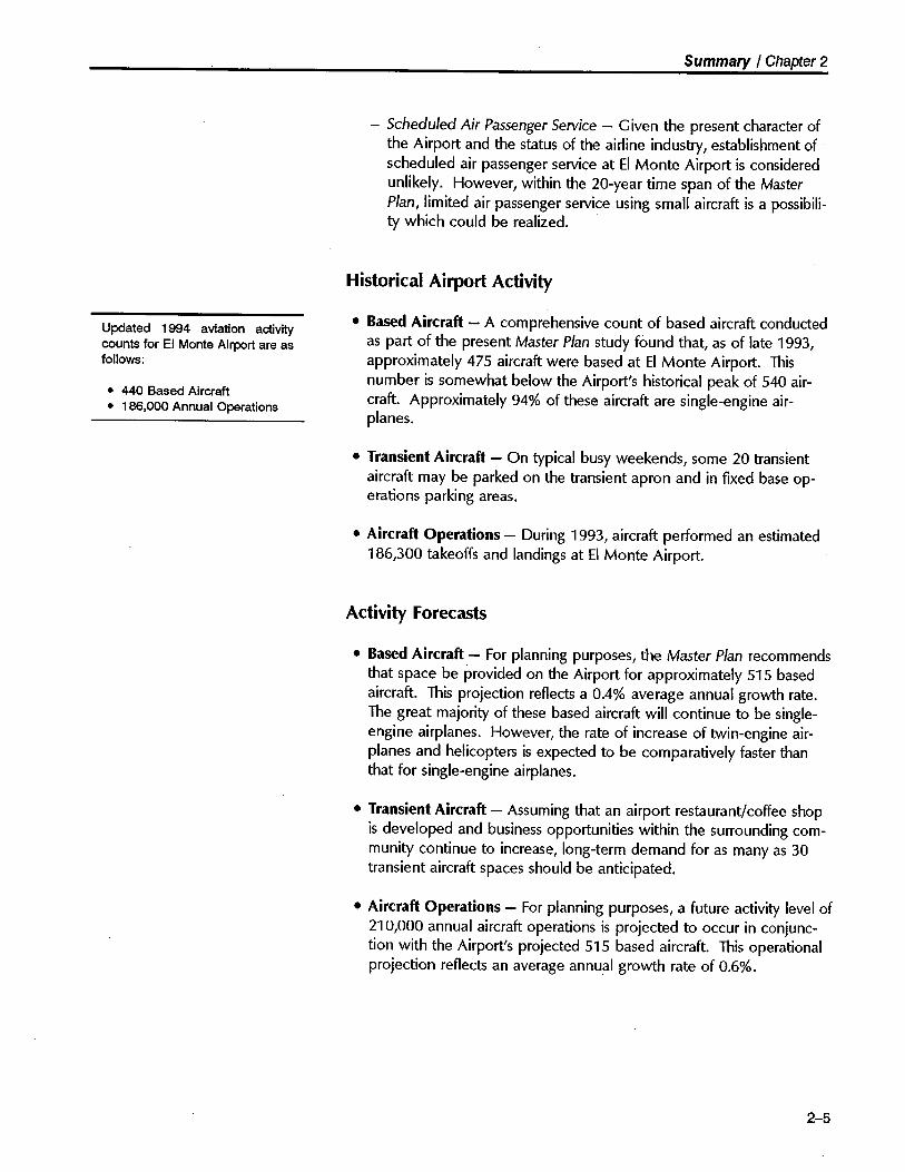
Updated 1994 aviation activitycounts for EI Monte Airport are asfollows:
. 440 Based Aircraft· 186,000 Annual Operations
- Scheduled Air Passenger Service - Given the present character ofthe Airport and the status of the airline industry, establishment ofscheduled air passenger service at EI Monte Airport is consideredunlikely. However, within the 20-year time span of the MasterPlan, limited air passenger service using small aircraft is a possibili-
ty which could be realized.
Historical Airport Activity
· Based Aircraft - A comprehensive count of based aircraft conducted
as part of the present Master Plan study found that, as of late 1993,approximately 475 aircraft were based at EI Monte Airport. Thisnumber is somewhat below the Airport's historical peak of 540 air-craft. Approximately 94% of these aircraft are single-engine air-planes.
· Transient Aircraft - On typical busy weekends, some 20 transient
aircraft may be parked on the transient apron and in fixed base op-erations parking areas.
· Aircraft Operations - During 1993, aircraft performed an estimated
186,300 takeoffs and landings at EI Monte Airport.
Activity Forecasts
· Based Aircraft - For planning purposes, the Master Plan recommends
that space be provided on the Airport for approximately 515 basedaircraft. This projection reflects a 0.4% average annual growt rate.The great majority of these based aircraft will continue to be single-engine airplanes. However, the rate of increase of twin-engine air-planes and helicopters is expected to be comparatively faster thanthat for single-engine airplanes.
· Transient Aircraft - Assuming that an airport restaurant/coffee shop
is developed and business opportunities within the surrounding com-munity continue to increase, long-term demand for as many as 30transient aircraft spaces should be anticipated.
· Aircraft Operations - For planning purposes, a future activity level of210,000 annual aircraft operations is projected to occur in conjunc-tion with the Airport's projected 515 based aircraft. This operationalprojection reflects an average annual growth rate of 0.6%.
2-5

Summary / Chapter 2
See Chapter 5 for the complete
discussion of airfield design is-sues.
2-6
Capacity Analyses
· Ainield Capacity - Airfeld capacity measures the number of aircraft
takeoffs and landings that can occur over a given period of time withan acceptable level of delay.
- Hourly Capacity - The EI Monte Airport runway/taxiway system
can accommodate approximately 95 VFR aircraft operations perhour or 12 IFR operations per hour.
- Annual Capacity - Annual capacity calculations are highly depen-dent upon assumptions regarding the levels of peak versus off-peak activity. Given the Airport's present peaking characteristics,the existing annual capacity of the runway/taxiway system is ap-proximately 220,000 operations. This capacity is adequate toaccommodate foreseeable future demand.
· Building Area Capacity - Relatively little land remains undevelopedwithin the present 103 or so acres of land area at the Airport. Future
building area requirements include the need for a public terminalbuilding/coffee shop, additional aircraft storage hangars, and varioustenant support facilities.
· Environmental Capacity - Environmental capacity, typically measur-ed in terms of cumulative noise impacts, is not a major constraint atEI Monte Airport. Measures to minimize noise-related conflicts be-tween the Airport and its surroundings are nonetheless importnt andshould continue to be emphasized.
PROPOSED AIRFIELD IMPROVEMENTS
The airfeld portion of EI Monte Airport consists of the 3,995-foot pavedrunway and taxiway system, together with Runway Protection Zones,required safety areas, and visual approach/landing aids.
Basic Design Factors
· Design Aircraft - Nearly all of the aircraft now operating or expect-
ed to operate at EI Monte Airport typically have approach speeds of121 knots or less, wingspans of less than 49 feet, and weigh 12,500pounds or less. The FAA airport design classification for this family ofaircraft is Airport Reference Code (ARC) B-I/Small. For airfeld designpurposes, the "critical aircraft" is the Cessna Citation I (CE-500) - asmall corporate jet.

Summary / Chapter 2
- Somewhat larger and/or faster aircraft (e.g., corporate turbo-propsand light jets) operate to/from the Airport on an occasional basis.However, use is limited by available airfield facilities - primarilyrunway length.
- In addition, the Airport is experiencing increasing use by small- to
mid-size helicopters. This activity is expected to continue to in-crease in the future.
· Ainield Configuration - Due to physical and economic factors, the
current configuration of EI Monte Airport's runway/taxiway systemwil remain essentially the same as is throughout the 20-year planningperiod. The rather unique paved continuous drift-off taxiway systemis seen as a useful facility enhancement and should be retained.
Runway Design
· Runway Extension Option - Due to the presence of immovableclose-in obstructions, the extension of Runway 1-19 is problematic.In addition, no demonstrable need for a runway longer than thecurrent 3,995 feet has been identified as part of the present MasterPlan study. Accordingly, the current runway length of 3,995 feet isexpected to remain the same throughout the 20-year planning timeframe.
· Displaced Threshold Locations - The Master Plan recommends that
the current locations of the Displaced Thresholds be maintainedthroughout the 20-year planning period. The current threshold dis-placements (Runway 1 - 290 feet and Runway 19 - 641 feet) pro-vide a clear 20:1 Threshold Siting Surface over objects located withinthe approaches to the Airport's runway.
· Declared Distances - As noted previously, the basic configurationand length of EI Monte Airport's Runway 1-19 is well defined byexisting facilities and site constraints. To take maximum advantage ofthe constrained site, the runway design identified in the Master Plan
incorporates the use of Declared Distances as an alternative to amore conventional runway configuration.
The calculation of EI Monte Airport's Declared Distances is basedupon the following design factors:
- Existing Runway 1-19 pavement (3,995 feet) will be retained;- Existing runway threshold displacements will be retained;
- Certain key obstructions within the runway approach and depar-ture surfaces wil be removed or otherwise mitigated; and
- Departure surfaces will provide 20:1 clearance over obstructions.
2-7

Summary / Chapter 2
The resultant Declared Distances for Runway 1-19 are as follows:
- Takeoff Runway Available (TORA)
Runway Runway1 1a
3,505' 3,995'
3,995' 3,995'
3,755' 3,995'
3,465' 3,354'
- Takeoff Distance Available (TODA)
- Accelerate - Stop Distance Available
(ASDA)
- Landing Distance Available (LDA)
Other Ainield Design Issues
· Instrument Approach Capability - To enhance the Airport's existingnon precision circle-to-Iand instrument approach capability, the MasterPlan recommends establishment of a new nonprecision straight-ininstrument approach to Runway 1. This approach would most likelybe based upon the emerging Global Positioning System (GPS) tech-nology.
· Helicopter Facilities - To better accommodate primarily transienthelicopter operations, the Master Plan recommends that a helicopterlanding/takeoff pad be designated on the parallel taxiway adjacent tothe transient helicopter parking area. Helicopters based at the Air-port wil continue to operate directly to/from their respective on-airport facilities.
· Visual Approach Aids - The airfield lighting system (i.e., runway andtaxiway lights) should be replaced/rehabilitated within the next 5 to10 years.
- Runway End Identification Lights (REIL) should be installed at thelanding threshold of Runway 1 to enhance pilots' visual recogni-tion of the threshold environment.
- It is suggested that a supplemental wind cone be installed nearmid-field, possibly on top of the fuel island kiosk.
· Automated Surface Observation System - As part of the NationalWeather Service's nationwide program to enhance airport weatherobserving capability, EI Monte Airport is programmed to receive anAutomated Surface Observation System (ASOS). The Master Planrecommends that the ASOS equipment array be located on the westside of the Airport - near the existing wind sensor equipment.
2-8

Summary I Chapter 2
BUILDING AREA DEVELOPMENT
The building area of an airport encompasses all of the airport propertnot required for airfeld purposes. At EI Monte Airport, the building areais located entirely to the east side of the runway/taxiway system.
Design Considerations
· FAA Airport Design Standards - All building area structures, fixedobjects, and aircraft parking areas must be located so as to complywith FAA design standards. At EI Monte Airport, the appropriatepresent and future FAA design category is Airport Reference Code B-I/Small. A straight-in non precision instrument approach to Runway 1is anticipated and should be provided for in the layout and use of the.building area.
· Demand Characteristics - The bulk of the demand for EI MonteAirport building area facilities will be generated by light general avia-tion aircraft - both airplanes and helicopters. It can be anticipated,however, that the Airport will see occasional use by medium-sizecorporate turboprop aircraft and small corporate jet aircraft.
· Land Availability - The existing building area offers suffcient land
area to accommodate projected aeronautical demand over the 20-year planning period. Acquisition of additional land area may proveadvantageous in maximizing area economic development opportuni-ties.
· Public Facilities - The Airport does not currently offer a public ter-
minal building. Many airport users have emphasized the desireabliltyof having an on-airport restaurant/coffee shop - possibly located inthe terminal building.
· Aircraft Storage Hangars - The airport user survey indicates thataircraft operators would like to see additional aircraft storage hangarsdeveloped at EI Monte Airport. Future growth of EI Monte Airport'sbased aircraft population will, in large measure, be dependent uponthe availability of suitable aircraft storage hangars.
· Airport User Access - Airport ground access is currently considered
to be excellent, and this high level of accessibility should be main-tained.
· Development Staging - The staging of improvements to the buildingarea must be well-timed and coordinated. The objective is to have aplan that is flexible enough to adapt to changes in type and pace offacility demands, is cost-effective, and also makes sense at each stageof development.
2-9

Summary / Chapter 2
Proposed Building Area Improvements
· Aircraft Storage and Parking - One of the primary roles of EI MonteAirport is to serve as a convenient location for the basing of lightgeneral aviation aircraft. Accordingly, siting and development ofadditional aircraft storage hangars and tiedown positions has beenprovided for in the Master Plan. Approximately 50 additional hangarunits are depicted on the Airport Layout Plan and Building Area Plan.
The existing tiedown aprons wil be adequate to accommodate antici-pated decreasing future tiedown demand. Some rearrangement oftiedown areas may prove advantageous in accommodating increasinghelicopter activity and development of new aircraft storage hangars.
· Public Terminal Building - The Master Plan provides for the con-
struction of a new public terminal building. The new terminal build-ing should be developed in the east/central portion of the Airport.The new building could include a restaurant/coffee shop, airportadministration/operations offces, pilot/passenger lounge, flight plan-ning area, community meeting room, and 24-hour accessible publicrest room facilities and telephones.
· Fixed Base Operations - There are four principal areas on the Air-port utilized for fixed base operations.
- The existing fixed base operations facilities are well located andconfigured, both the present and the future.
- A fifth fixed base operation could be developed in the conven""tional hangar located immediately west of the air traffc controltower. This site could I~nd itself to development by a helicopter-oriented fixed base operator.
- A 32,000-square-foot area of undeveloped land in the east-centralportion of the Airport should be reserved for development in sup-port of fixed base operations.
· Aviation Fueling Facilities - Two of the Airport's underground avia-tion fuel storage tanks will eventually need to be replaced. The Mas-ter Plan recommends that the replacement underground fuel storagetanks be located on the same site as the existing facilities. It is fur-ther recommended that "self-service" credit card operated fuelingcapability be provided at the fueling island.
· Other Building Area Facilities - The following facilities are identifiedas integral elements of the Building Area Plan:
- Second Aircraft Wash Rack - The Master Plan suggests that asecond aircraft wash rack be provided on the north end of theAirport. This wash rack must comply with CEQA/EPA environ-mental requirements.
2-10

Summary / Chapter 2
See Chapter 7 for the complete
discussion of land use and en-vironmental issues.
- Tenant Aircraft Maintenance Shelter - To provide enhanced tenantamenities, the Master Plan suggests that a tenant aircraft mainte-nance shelter be provided near the present aircraft wash rack.Typically, such a shelter consists of a one- or two-bay all-metalstructure equipped with electrical power, work bench/vice, over-head lighting/skylights, fire protection, waste oil disposal tank, andin some cases, compressed air. The purpose of this shelter is topermit airport-based users and tenants to work on their own air-craft (in accordance with FAR Part 43) in a safe, convenient, andcontrolled facility. The County has used one of the hangars in the"1" hangar row for this purpose in the past.
- Future Building Area Land Acquisition - Contiguous to the Air-port's building area is an 8-acre parcel of land currently beingused as a school (Mulhall Elementary). Should this parcel becomeavailable on the open market, serious consideration should be
given to its acquisition for airport economic support purposes.
· Supplemental Aviation Support Area - The Airport ow'ns as-acreparcel of undeveloped land located across Santa Anita Avenue fromthe approach end of Runway 1. It is recommended that this parcelbe developed in a manner that is compatible with airport operationsand that contributes economically to the Airport. Potential uses forthis area include: automobile parking, single-story offces, light in-dustrial, low-density retail sales, and mini-storage facilities.
LAND USE AND ENVIRONMENTAL ISSUES
Despite the existing intensive urban, and especially residential, land usesaround EI Monte Airport, compatibility has not been an issue. Thisstatus is undoubtedly attributable to the limited nature of airport opera-tions (predominantly light, general aviation airplanes), the busy, relativelynoisy character of the surrounding area, and the mutual understandingof each other's concerns by pilots and area residents. Recommenda-tions in the Master Plan therefore focus on further promoting an aware-ness of compatibilty concerns and identifying actions which should betaken to prevent problems from arising.
Compatibility Concerns
· Noise Impact - The Airports noise impact area wil expand slightlyover the 20-year planning time frame as a result of the projected13% increase in total aircraft operations plus a small shift towardhigher proportions of helicopters and twin-engine propeller airplanesin the fleet mix. A portion of the Daleview Trailer Park lies within theexisting 65-CNEL contour and a few more units will be within the
2-11

Summary I Chapter 2
future expansion of this contour. For the most part, though, the areaprimarily affected by aircraft noise at each end of the runway pre-dominantly consists of commercial and industrial land uses.
· Safety Status - The most critical locations with regard to safety arethe Runway Protection Zones and immediately adjoining areas. Al-though the Airport owns less than half of the land within each of thetwo future RPZs, most of the remaining propert consists of road andrailroad rights-of-way and the Rio Hondo flood control channeL.Except for the flood control channel, the freeway, and major roads,few open spaces suitable for emergency aircraft landings remain inthe airport vicinity.
· Specific Concerns - Because the character of both the Airport andthe surrounding land uses is well established, little change in the cur-rent compatibility status is expected to occur in future years. Theparticular compatibility concerns which need to be monitored to en-sure that they do not develop into major problems in the future in-clude:
- Noise impacts on the Daleview Trailer Park.
- The high number of schools in the airport vicinity (although noneare located within the runway approach zones).
- The potential for construction of tall structures in the airport flightpaths, particularly in the vicinity of the transit terminals south ofthe Airport.
Land Use Compatibility Measures
· Fee Simple TTtle Acquisition - No compatibility conditions warrant-ing outright acquisition of propert near EI Monte Airport arecurrently apparent or anticipated. Nonetheless, the County shouldcontinue to keep this option open if it should become necessary forprotection of the critical areas in the runway approaches.
· Avigation Easement Acquisition - An existing avigation easement
covers the portion of one private propert situated within the Run-
way Protection Zone for Runway 19. This easement, however, doesnot extend to additional portions of the parcel which will be affectedby the future increase in RPZ size resulting from establishment of astraight-in instrument approach. Expansion of the easement coverageon this propert is recommended.
· Approach Protecion Easement Acquisition - Approach protectioneasements - a combination of an avigation easement and the acqui-sition of development rights to a propert - could be of value as analternative to outright acquisition as a means of preventing new, .
2-12

Summary I Chapter 2
more incompatible development on critical propertes near the run-way ends.
· Land Use Designations - The existing general plan and zoningdesignations in the airport environs largely reflect the existing landuses. Short of major redevelopment, significant changes are notanticipated. The one location for which designation of a differentland use category would be beneficial from an airport compatibiltystandpoint is the mobile home park north of the Airport. Some typeof light industrial use would be more suitable for this site. It is recog-nized, though, that this change is not likely to occur unless it were tobe supported by factors other than airport compatibility.
· Airport Overlay Zone - The City of EI Monte has adopted a type of
airport overlay zone in the form of the Airport Approach HeightZone. Any future proposals for high-rise development or any tallstructures in the airport vicinity - and especially in the runway ap-proach corridors - should be carefully reviewed with respect to theairspace protection criteria established by that ordinance.
· Buyer Awareness - Buyer awareness is an umbrella category forthree types of measures whose objective is to ensure that prospectivebuyers of propert in the vrcinity of an airport are informed about theairport's impacts on the propert. Two of these types - avigationeasement dedication and recorded deed notices - are generallyapplied only to new development. A more useful type of buyerawareness with respect to EI Monte Airport is to promote the needfor disclosure of the Airport's proximity and impacts as part of nor-mal real estate transactions involving propert in the airport vicinity.As airport owner, the County of Los Angeles should provide local realestate brokers, as well as EI Monte and the other nearby cities, withinformation identifying the areas affected by the Airporrs traffc pat-terns. Having received this information, the real estate agencieswould be obligated to pass it along to prospective propert buyers.Thè affected cities are encouraged to adopt policies promoting thisform of buyer awareness program.
Airport Facility and Operational Measures
· Purpose - Airport facility and operational measures represent theother side of the compatibility coin in that they are intended to en-sure that airport activity does not grow or change in a manner thatwould create new conflicts with already existing land uses.
· Facility-Related Measures - Most of the facility-related types ofcompatibility measures which can be taken at general aviation air-port have already been implemented at EI Monte Airport. These
include capacity limitations (implemented by default because of the
2-13

Summary / Chapter 2
Financial and plan implementationtopics are examined in length inChapter 8.
2-14
. lack of expansion capabilities), landing threshold displacements, andvisual glide slope indicators with high approach slope angles.
· Operational Measures - Only minimal opportunities for limiting theairport's impacts by operation measures are apparent and the lackof significant problems minimizes the need for such actions. Asairport activity increases in the future, some restrictions on touch-and-go operations may become necessary not only for noise purpos-es/ but also for reasons of safety and capacity. Projected increases inhelicopter activity at the Airport may necessitate examination ofhelicopter flight routes and their relationship both to airplane traffcpatterns and to noise-sensitive land uses. Perhaps most importnt inthis category of actions is for airport management and fixed baseoperators to continue their effort to educate pilots regarding noise
abatement techniques.
Environmental Issues
As an integral element of the Master Plan, an Initial Study of environ-mental impacts was performed (see Appendix J). The Initial Study con-cluded that the sum of the airfeld development proposed in the MasterPlan represents a mitigable impact on the environment. Accordingly, itis recommended that a NEGATIVE DECLARATION be prepared.
FINANCIAL AND IMPLEMENTA nON ISSUES
The financial element of the Master Plan addresses the timing of theproposed airport improvement projects, the estimated costs of theseimprovements, and anticipated future airport revenues and expenses.
Capital Improvement Program
· Project Staging - Table 2A lists the airport improvements proposedin the Master Plan. Also indicated is the timing of the recommendedimprovements, as well as their estimated costs (in 1994 dollars).
· Short-Range Projects - The major projects slated for construction inthe short-range (within five years) are as follows:
- Construct aircraft storage hangars (initially, 30 units)- Construct terminal building,
- Install Automated Surface Observation System (ASOS), and- Renovate aviation fuel storage facilities.

Summary I Chapter 2
Estimated Costs (in 1994 $ values))
Totaia Federaib Airport. Short-Range Projects (Within 5 Years)
Obstruction removal
Install Runway End Identification Lights (REIL) - Runway 1
Install Automated Surface Observation System (AS OS)
Renovate aviation fuel storage facilities including monitoringsystem for three underground fuel storage tanks and installation ofself-service fuel dispensing equipmenf
Construct terminal building (4,000 sf) including site preparation,structure, and adjacent auto parking lotd
Construct aircraft storage hangars (30 hangar units - northeastarea)
Construct second aircraft wash rack
$ 75,000 $
13,000
85,000
75,000
625,000
690,000
30,000
33,000
20,000
$1,646,00
Construct tenant aircraft maintenance shelter (2,500 sf)
Install automatic controlled-access vehicle gate (A TCT parking lot)
Subtotal
67,500 $
11 ,700
76,500
100,000
50,000
18,000
$ 323,700
45,000
7,500
1,300
8,500
75,000
525,000
640,000
30,000
33,000
2,000
$1,322,300Mid-Range Projects (5 to 10 Years)
Construct aircraft storage hangars (20-22 units - east-central)
Pave/site prep grassy area (32,000 sf)
Replace airfield lighting system including runway lights andtaxiway lights
Pavement rehabilitation
545,000
65,000
320,000
920,000
$1,850,000
2,342,000 2,107,800 234,200
6,650,000 5,985,000 665,000
$8,992,000 $8,092,800 $ 899,200
$12,488,000 $ 9,577,500 $2,910,500
Subtotal
Long-Range Projects (Beyond 10 Years)
Pavement rehabiltation
Acquire property (8 acres)
Subtotal
TOTAL
288,000
828,000
$1,161,000
500,000
65,000
32,000
92,000
$ 689,000
Notesa Estimated construction costs based upon preliminary engineering designs; actual costs wil depend upon detailed
designs and specifications; engineering costs and contingencies included. Estimated land costs based upon anticipatedacquisition costs plus escalation factor, administrative costs, and contingencies.
b Federal funding for eligible projects calculated at 90% based upon current legislation. Local share equals 10%. State
funds could be used (but are not expected to be) on many of the projects in lieu of federal funds.C If replacement of the three underground fuel storage tanks is required, the estimated total cost is $250,000.
d County funding of terminal building structure and public-use areas is assumed, although entire building could be
privately financed. Federal funding for a portion of the project also may be possible.
Source: Hodges & Shutt (September 1994)
Table 2A
Proposed Airport ImprovementsEI Monte Airport
2 - 15

Summary / Chapter 2
· Costs - The total estimated cost of the projects identified in theMaster Plan is approximately $12.5 million. Of this amount, roughly13% ($1.6 milion) is proposed for short-range implementation.
· Funding Sources - It is suggested that the recommended airportimprovements be funded through a combination of Federal AviationAdministration, California Division of Aeronautics, Los Angeles Coun-
ty airport system funds, and private sources.
- The FAA Airport Improvement Program is the largest single sourceof proposed funding. $9,577,500 of the total improvements areeligible for FAA grants. $323,700 of this amount is for short-rangeprojects.
- The anticipated Los Angeles County share of the improvementcosts over the 20-year Master Plan period is $2,910,500. Themajor improvements requiring significant County funding are con-struction of the new terminal building, renovation of the aviationfuel storage facilities, and construction of aircraft storage hangars.Terminal buildings at reliever airport are currently eligible forpartial FAA AlP funding. Aviation fuel storage facilities are not. Itis anticipated that the County airport system will fund the con-struction of all aircraft storage hangars - approximately 50 addi-tional hangar units. State loan program funds, if available, can beused to finance hangar development and fuel farm renovation.
- It is anticipated that the private sector will fund the developmentof all fixed base operations and specialty aeronautical facilities.
Financial Projection
· Summary - EI Monte Airport's projected operating income andretained earnings wil be suffcient to totally fund the sponsor's shareof the Capital Improvement Program costs over the initial 5-yearfinancial planning period. During this period, supplemental fundingand/or interim financing from the Los Angeles County airport systemmay be required to provide for the timely and cost-effective imple-mentation of EI Monte Airport's Capital Improvement Program.However, EI Monte Airport revenues should be suffcient to fullyrepay such supplemental funding.
Over the course of the 20-year planning period, it is anticipated thatairport revenues will continue to remain strong. The Airport willremain capable of operating on a break-even basis and be fully cap-able of funding all of its capital requirements. Airport revenue couldbe enhanced by developing new sources of airport-related revenueand/or by increasing the rates charged to airport lessees, permitteesand users. Caution must be exercised, however, in establishing high-er rates at the Airport. A reasonable balance must be sought among
2-16

Summary I Chapter 2
such factors as the need for a financially viable airport, public airaccess considerations, the continuation of indirect subsidies to theprivate sector, and general aviation market conditions. In this regard,the Airport's rates and fees structure should be established in a man-ner which permits the Airport operator to safely operate and improvethe Airport while attacting and serving the Airport's target usergroups.
Financial Recommendations
. · Revenue/Expenses - The Airport operator should continue to aggres-sively develop all revenue resources and strictly control and minimizeall operating expenses.
· Rates and Charges - Airport rates and charges should be reviewedand adjusted on a regular basis to ensure that maximum reasonablerevenue is generated consistent with the Airport's role, facilities, anduser demand.
· Encourage Development - Additional private and commercial avia-tion development on the Airport should be encouraged to bolsterAirport revenues and service offerings.
Master Plan Adoption
An Initial Study covering the im-provements proposed by theMaster Plan is documented in
Appendix J of the Master Plan
Report.
· Environmental Impact Documentation - It is anticipated that anInitial Study, prepared in accordance with California Environmental
Quality Act guidelines and Los Angeles County's environmental re-view requirements, will be suffcient to enable preparation of a Nega-tive Declaration allowing adoption of the Airport Master Plan. AnInitial Study, covering the improvements proposed by the Master Plan,has been prepared as an integral element of this master planning pro-cess.
· Plan Review - The Los Angeles County Aviation Commission, and
the Los Angeles County Regional Planning Commission (designatedAirport Land Use Commission) each will be involved in the review ofthe Airport Master Plan.
- The Los Angeles County Aviation Commission reviews the overallplan and makes recommendations regarding its adoption to theBoard of Supervisors.
- The Los Angeles County Regional Planning Commission, in its roleas the designated Airport Land Use Commission, will also reviewthe Master Plan as part of the adoption process.
2-17

Summary / Chapter 2
· Board of Supervisors - The Los Angeles County Board of Supervis-
ors has the ultimate responsibility for adoption of the Airport MasterPlan.
· Federal Aviation Administration - Following adoption of the Master
Plan by the County, the FAA will formally review and approve theAirport Layout Plan drawing as the basis for future engineering designand grant eligibility of specific projects.
Implementation
· Project Funding - Once the Master Plan has been adopted and a
decision has been made to proceed with implementation, the Countyshould soon thereafter submit an Airport Improvement Program grantpreapplication to the FAA.
· Engineering Design - The County may choose to enter into a con-tractual arrangement with a qualified airport engineer to prepare thedetailed engineering designs for the proposed improvements. Toassure continuity in design and development, it is suggested that theagreement cover not just the immediate projects, but other majorimprovements proposed to be constructed over the next 3 to 5years.
2-18

3
Backgroundand
Inventory

A brief profile of EI Monte Airport'smajor features, air traffic proce-dures, management and services,and environs is presented in Table3A. The accompanying para-graphs highlight a number of keypoints.
3
Background and Inventory
EL MONTE AIRPORT
Location and Environs
EI Monte Airport is located in the north-central portion of the greaterLos Angeles metropolitan areai some 11 statute miles east-norteast ofcentral Los Angeles and 10 statute miles southeast of Mount Wilson (seeFigure 3A). The Airport, comprising 103.3 acres, lies entirely within theCity of EI Monte incorporated limits at an average elevation of 296 feetabove Mean Sea LeveL.
Most of the land surrounding the Airport consists of heavily urbanizeddevelopment - both residential and commercial/industrial uses. Virtuallyno undeveloped propert remains. The western edge of airport propertabuts the Rio Hondo Flood Control ChanneL. A Southern Pacific Rail-road right-of-way and a major thoroughfare (Santa Anita Avenue) abutairport propert to the south. To the north, the Rio Hondo Flood Con-trol Channel and a major thoroughfare/bridge (Lower Azuza Road) de-fine the limits of airport propert. To the east of the Airport, residentialdevelopment comprises the bulk of the land use.
EI Monte Airport is well-located with respect to access from local areastreets and regional highways. Lower Azuza Road and Santa Anita Ave-nue provide convenient local road access to the Airport. InterstateHighways 10/605/ and 210 pass within 5 statute miles of the Airport.
A Metro-Link public light-rail transit station is located 2 blocks to thesouth of EI Monte Airport at the intersection of Tyler Avenue and theSouthern Pacific Railroad right-of-way. In addition, an RTD regional busterminal is located in this same area. There is no public transit serviceavailable to or from the Airport itself.
3-1

Background and Inventory / Chapter 3
MAJOR FEATURES
Propert· EI Monte Airport encompasses approximately 103 acres of propert owned by Count of Los Angeles.
· Airport propert includes the single runway/taxiway system and the entire building area, including a 5-acre noncon-
tiguous parceL.
· Approximately 42% of the two existing Runway Protection Zones locted on airport propert.· The Airport holds a 0.5-acre protective aeronautical easement underlying a portion of the approach to Runway 19.
Airfield· Runway 1-19 is 3,995 feet long and 75 feet wide; the Runway 1 threshold is displaced 290 feet and the Runway 19
threshold is displaced 641 feet. The runway surface is composed of asphaltic concrete.· Runway 1-19 is equipped with a Medium-Intensity Runway Lighting system (MIRL).· Runway 1 is equippd with an AVASI-L (angle 4.95°); Runway 19 is equippd with an AVASI-R (angle 4.5°) and
REIL. The runway has BasicNisual markings and signs.· A full-length paved continuous drif-off area and parallel taxiway are located on the east side of Runway 1-19. A
hOlding bay /runup area is locted at the entrance to each runway approach end.· There are numerous penetrations of the Airport's FAR Part 77 approach and transitional surfaces.· A Rotating Beacon (white-green) is locted in the east-central portion of the airfield.
Building Area· Located entirely to the east side of the runway/taxiway system.· Aircraft parking and storage facilities:
- 315 aircraft tieclwns (including 28 designated for transient airplanes and 5 for transient helicopters)- 274 aircraft storage units, a mix of conventional, T-hangar, and box types.
- 310 automobile parking spaces in the various fixed base operations areas.· Major aviation-related businesses/facilties:
- FAA-staffed air traffic control tower (operates daily 1430Z-0S00Z).
- Four conventional fixed base operations hangars with automobile parking areas.
- Count operations/maintenance facility (offce/garage and storage yard) located in easternmost corner of airportpropert.
- Underground aviation fuel storage and dispensing faciliies locted in the center of the apron area.- Airport users' rest room facilties locted throughout hangar areas.
- Aircraft washrack located adjacent to eastern boundary.
- Compass calibration rose in northeast corner of Airport.
AIR TRAFFIC PROCEDURES
Visual Procedures· Traffic Pattern:
- Pattern altitude is 1,300 feet MSL (approx. 1,000 feet above airport elevation).
- Non-standard right pattern for Runway 19 fixed-wing aircraft traffic.- Helicopters utilze a traffic pattern-based approach/departure procedure.
- Prevailng wind direction favors Runway 19 approximately 90% of the time.
Instrument Procedures· Three "circle-to-Iand" non precision instrument approach procdures serve the Airport.
- VOR or GPS-A: Lowest minimums are 484 feet AGL/1 statute mile visibilty.- VOR DME or GPS-B: Lowest minimums are 1,044 feet AGL/1.25 statute mile visibilty.- NDB or GPS-C: Lowest minimums are 664 feet AGL/1 statute mile visibilty.
· A non-directional radio beacon (NDB) is located on the Airport - EL MONTE NDB (MHW (§ 359 kHz "EMT".· Aircraft are permitted to depart the Airport under IMC via the published IFR Departure Procedure or otherwise in
accrdance with IFA.
Table 3A
Airport ProfileEI Monte Airport
3-2

Background and Inventory I Chapter 3
AIR TRAFFIC PROCEDURES - continued
Airspace· The Class B airspace assocated with Los Angeles International Airport is located 1.5 statute miles south of EI Monte
Airport from 3,704 feet to 12,204 feet above airport surface.· EI Monte Airport is located within the Los Angeles 30 NM Mode C Requirement Area.· Locted within 8 miles of EI Monte Airport is Class C airspace for Burbank-Glendale-Pasadena Airport.
On-Site Supervision· COMARCO employees are on dut at the Airport 24 hours per day - 365 days per year.· Additional administrative support is available through the Los Angeles Count Aviation Division.
Fixed Base Operations· Eight fixed base operators are located at the Airport.· Services provided include: fixed-wing and rotary-wing aircraft rental, flight and ground instruction, aircraft maintenance
and repair, aircraft engine maintenance and overhaul, avionics, aircraft sales, pilot supplies, air freight, and aircraftcharter.
Aviation Fuel Service· COMARCO dispenses all aviation fuel on the Airport.· Available fuel grades are 100LL aviation gasoline and Jet-A turbine fueL.· Fuel is dispensed from a fixed loction in the central apron area (100LL) and via refueler truck (100LL and Jet-A).
Emergency Services and Security· On-site surveilance, security, and initial emergency response is provided by COMARCO airport staff.· Locl police and fire response provided by City of EI Monte.
ENVIRONS
Topography· Airport elevation is 296 feet above Mean Sea LeveL.· Terrain slopes upwards to the north.
Design Temperature· Mean-maximum, hottest month: 92.8.F.
Ground Access· Airport located adjacent to Santa Anita Avenue between Lower Azuza Road and Valley Boulevard.· Airport locted 1.5 miles from Interstate Highway 10 and nearby Interstate Highways 605 and 210.
· Airport is served by three controlled-accss gates - two off Santa Anita Avenue, and one off Emery Avenue.
Ground Transportation· No direct public ground transportation to/from the Airport.· Taxicabs and rental cars are available at the Airport through prior arrangement.· Metro-Link light rail and RTD bus service stations are locted 2 blocks from the Airport.
Jurisdiction· Airport is located entirely within the City of EI Monte in the Count of Los Angeles.
Source: Compiled by Hodges & Shut (January 1994)
Table 3A - Continued
3-3

Background and Inventory I Chapter 3
~
J \ \~G \: i r- J . 1:. ii 1= ,d ~~-\"I"C'-1- -- nr r-~ II t I~. \ \ r T Y -- F i l t "\ Ift D i "-_ -- J Li \~tj\J~ 1-r- i L ~ J -" J L j., ò t- a __.. í \
. \. \ -'\ ~ - - --1C_.r-- -:,;::-=-=-=.:~:;'--- ~o: ~ \\\ \~bf- -- d --- ~ ~\L\- i ev \ \ . __-,B------ \ ~ ': ò (J \ ' ~ ""
\
\~ r-\ ~ ~ x; /? % /.. ~ yö \ ,"J! -' \\~ \ -, 1\ .-t ~ / ~ \-p ~\ / ö-\ \\\\~~~r J h ,'"," L - ~_ _----- - - ~--;nl \ -C. 6' '" !!~ Emery
r- ¡ "Qrs.o ff§f~ Emery St i/'_, --'! p .... ; -- c' Ö!" . JtR S;sb . \'"/ /..ì. .I . ~....- '/ : \ ~./ L ~ li'C'1r ,,0 a: ~L_ J i . Sg" r_O" er" r . BaS-i -j .rant 0 Ye
lì -r- /s Ì7f- r iv. Ö t-¡ _ J /: - ìj: --
I
T
............Y
~I_-oJr-i 'D
i
'- ........
- Q:
j\ \ \-?°Od
,, ROOd
L6srt
"Iv.TJl¡e- 1fOÖ 'ItScito
--¡IIMOnt.
~~'" !/Stt- &lvC/!S(
~
Dri",
._~---~- --- - -- '-. ~ I/~S"'"~,o~~~~ ;~';"~ -J I -I Garveyi~ L- r:- - r- ~-. : i '-r-.J I
Ö
\
\B~i
J - Ro~~o "'''i
/CfT Y OF E L MONTE"".. /. .A _7" ~/ A)( r
T çJ
'"Q¡
Fr",. SWOy
\1- y--¡ \
\
If I-
0 t 3.000
Feet
/I I
-
AvenueII \ /" --V/t I i-Y_)
3 CUT r
L_¡ r-~ r- - -L ~____J I~ "r\ Ei: IL 'v, v ~ '\
I-f-- 1
,
Figure 3A
Airport VicinityEI Monte Airport
3 - 4

Background and Inventory I Chapter 3
Feet
Photo date: 1/3194,Figure 38
Airport Aerial ViewEI Monte Airport
3 - 5

Background and Inventory / Chapter 3
General aviation is defined as allcivil aviation activit except com-mercial air carrier operations.
Updated 1994 aviation activitycounts for EI Monte Airport are asfollows:
· 440 Based Aircraft· 186,000 Annual Operations
A detailed listing of existing facil-ties at EI Monte Airport is providedin Appendix A of this report.Figure 3B presents an aerial viewof the Airport and its immediate
environs.
3-6
Airport Development
Operational History
EI Monte Airport has been located at its present site for almost 60 years.The Airport was initially established in 1936 by Mr. Nick Lentine on 35acres of land in the old Rio Hondo Riverbed. During World War II, theAirport, like many other similar facilities, was temporarily closed for na-tional security purposes. After the war, EI Monte Airport was re-openedand operated as a privately owned, public-use general aviation facility.In 1965, the County of Los Angeles entered into a lease agreement withthe then owner, Mr. Robert Wanamaker, and took over the operation ofthe field. This action was taken by the County to preserve the Airportfor future public aviation use.
The County acquired EI Monte Airport in the late 1960's and soonthereafter began to improve both airport services and facilities. Over thepast 25 years, the County has expended federal, state, county, and air-port funds to further develop and improve the Airport to its current con-figuration and condition. The Airport is currently one of five generalaviation airport owned by the County of Los Angeles.
Throughout its 58-year operating history, EI Monte Airport has activelyaccommodated both based and transient general aviation aircraft. Bythe end of 1993, 475 aircraft were based at the Airport. Based andtransient aircraft generated approximately 186,300 annual takeoffs andlandings at EI Monte Airport in 1993.
Airfeld Facilities
EI Monte Airport has only one runway. Runway 1-19 is 3,995 feet longand 75 feet wide. Due to off-airport obstacles, each runway end ischaracterized by a displaced threshold. The runway's asphaltic-concrete
construction has a published weight bearing capacity of 12,500 poundsfor airplanes with single-wheel landing gear. Runway 1-19 is equippedwith medium-intensity runway lights and visual approach aids. Therunway is served by a paved full-length parallel taxiway with a pavedcontinuous drift-off area in lieu of the more typical runway exit taxiwayconfiguration. A holding bay/runup area is located at the entrance toeach runway approach end. The runway is marked and signed in accor-dance with Basic/Visual approach criteria.
Three non precision instrument approach procedures have been estab-lished to guide properly equipped aircraft to the Airport environs duringperiods of inclement weather. These three procedures are summarizedin Table 3A. Each of the instrument approach procedures utilizes adifferent navigational aid for directional guidance. The lowest availableinstrument approach minimums are associated with the VOR or GPS-Anonprecision procedure and are currently established at 484 feet above

Background and Inventory I Chapter 3
An inventory and description of EIMonte Airport's building areafacilties is presented in AppendixA.
airport elevation and 1 statute mile visibility. All of the approachesterminate in a circle-to-Iand or visual operation. Because of the region's
typically hazy/smoggy weather, the Airport's three instrument approachprocedures see frequent use.
In late 1994, EI Monte Airport's instrument approach capability wasenhanced with the implementation of G PS overlay approaches. Thisnationwide overlay program permits suitably equipped aircraft to con-duct certain nonprecision instrument approaches to airport using GPS(Global Positioning System) guidance and procedures. The three non-precision instrument approach procedures at EI Monte Airport are FAA-approved Phase Three G PS overlay approaches.
Building Area Facili6es
The majority of structures at the EI Monte Airport are aircraft storagehangars. Interior storage for approximately 274 aircraft is providedwithin these storage hangars. In addition, there are five conventional-style, fixed base operator-type (FBO) hangars totaling approximately40,000 square feet. There are no public terminal facilities other thanthose provided by the FBOs. Airport tenant-accessible rest rooms arelocated in the various hangar areas.
Aircraft tiedown/parking facilities are located throughout the Airport'sbuilding area. Approximately 315 aircraft tiedown/parking positions areavailable for use at the Airport. Approximately 61 % of the availablebased aircraft tiedown positions are currently in use.
Also located on the Airport is an FAA-staffed and operated air traffccontrol tower. This facility is operated on a part-time basis daily from6:30 a.m. local time through 9 p.m. local time. Airport weather infor-mation is provided 24 hours per day through control tower personneland contract weather observers.
Other on-airport facilities and structures include:
· Aviation fueling facility (including underground storage tanks, island-based dispensing equipment, and attendant kiosk)
· Aircraft wash rack· Electrical vaults· County maintenance garage/yard
· Civil Air Patrol offce/storage trailer· Security fencing, gating, lighting, and signing· Various automobile parking areas
The Airport owns a 5-acre parcel of undeveloped land located to thesoutheast of the Runway 1 approach threshold. This parcel is physicallyseparated from the Airport by Santa Anita Avenue.
3-7

Background and Inventory / Chapter 3
Airport Management and Operations
County of Los Angeles
EI Monte Airport is owned by the County of Los Angeles. The admini-stration and major capital development of the Airport is the responsibilityof the County's Departent of Public Works - Aviation Division. EIMonte Airport is one of five general aviation airport owned by theCounty .
The ten-member Los Angeles County Aviation Commission meetsmonthly to work with County staff and to advise the County Board ofSupervisors regarding the operation and development of the County'sairport system. All final policy decisions are the responsibility of the LosAngeles County Board of Supervisors.
COMARCO
Since April 1991, the day-to-day management, operation, and develop-ment of the Airport have been provided by COMARCO - a privatemanagement services firm working under contract to the County.COMARCO operates all five County-owned airport under the terms ofa 20-year operating agreement. Under this arrangement, the Countyretains administrative oversight and major capital project funding respon-sibilities, and COMARCO is responsible for the operation, maintenance,and development of the facilities.
An airport manager and supporting staff of 10 COMARCO employeesare normally stationed at the Airport. The on-site COMARCO airportpersonnel are further supported by COMARCO administrative and tech-nical staff based throughout the County airport system. COMARCOairport personnel stationed at the Airport are responsible for airportmanagement, operations, and maintenance. COMARCO personneldispense aviation fuel at the Airport. COMARCO personnel also pro-vide the Airport's initial response to on-airport emergencies. A County-owned emergency response vehicle (Ansul unit with 100 gallons of AFFFfoam and 450 pounds of Purple K) is stationed near the aviation fuelingfacility. COMARCO personnel are present at the Airport on a 24-hours-per-day, 365-days-per-year basis.
Aeronautical Service Providers
EI Monte Airport's numerous fixed base operators and specialty serviceoperators offer a variety of general aviation services to the public includ-ing aircraft rental, flight and ground instruction, aircraft maintenance andrepair, aircraft engine maintenance and overhaul, avionics, aircraft sales,aircraft charter, air freight/package delivery, pilot supplies, and autorental. The above services are offered primarily in support of fixed-wing
3-8

Background and Inventory / Chapter 3
A fixed base operation is a busi-ness operating at an airport thatprovides one or more aviationservices to the general public.Such services may include, butare not limited to, sale of aviationfuel and oil; new and used aircraftsales; aircraft rental, maintenance,and repair; parking, tieclwn,and/or storage of aircraft; flightand ground instruction; airtaxi/charter operations; and spe-cialty services, such as instrumentand avionics maintenance, aircraftpainting and upholstery, engine
overhaul, aerial application, andaerial photography.
airplanes. However, increasing helicopter activity in the Los AngelesBasin is generating new helicopter-related business interest among theAirport's various fixed base operators.
Most of the Airport's fixed base operations are conducted from dedicat-ed conventional hangars. One fairly recent fixed base operation, Univer-sal Air Academy, is utilizing an on-airport offce trailer and adjacentramp area for its operations.
TTedown space rental for both based and transient aircraft is provided bythe County and administered by COMARCO. The County and theprivate sector provide a mix of individual aircraft storage hangars - bothT type and box type. As noted previously, aviation fuel (1 DOLL and jet-A) is dispensed by COMARCO personneL.
There is no scheduled commercial air carrier or commuter air service atEI Monte Airport at the present time.
Federal Aviation Administation
The FAA operates a VFR-Level II air traffc control tower at EI MonteAirport. In-flight IFR coordination in the EI Monte area is provided bythe FAA's Ontario Approach Control. Other than the air traffc controltower facility itself, the FAA has no on-airport maintenance responsibili-ties.
AERONAUTICAL SEmNG
Area Airport
Due to the high population density and extensive commercial/industrialdevelopment in the greater Los Angeles metropolitan area, a relativelylarge number of airport are located in the vicinity of EI Monte Airport.Table 3B briefly describes the 14 airport - public, private, and military- located within 25 statute miles of EI Monte Airport. Of these 14airport, 12 are available for public use. It is anticipated that these 12airport will continue to serve as public-use aviation-related facilitiesthroughout the 20-year master planning period. No new airport are
expected to be developed within the subject area.
As the listing in Table 3B indicates, a number of these area airport arelarge, busy metropolitan airport serving complex, high-performance aircarrier and general aviation aircraft. Fullerton Municipal, Compton,Brackett Field, Whiteman,. and Chino airport serve somewhat the samegeneral aviation markets as does EI Monte Airport. The nearest public-use airport to EI Monte is Brackett Field, a County-owned general avi-
3-9

Background and Inventory I Chapter 3
Loçation Facllities2 Serices3
e::::!" commu~i":":":: County ir 1 ion Aircraft Rwys Long Surf Lgt Appr Gas Jet Mntn Rent Food ATC Psgr
E I Monte E I Monte Los - Public 475 1 3,995 Asph Yes NP X X X X - X -Angeles
Bracket LaVeme Los 14 E Puljic 484 2 4,839 Asph Yes Pre X X X X X X -Field Angeles
Burbk- Burbk Los 20 N1 Puljic 327 2 6,902 Asph Yes Pre X X X X X X XGlendae- AngelesPasadena
Chino Chino San 23SE Puljic 881 2 6,221 Asph Yes Pre X X X X X X -Bemadno
Comp:on Comp:on Los 18SW Puljic 352 2 3,670 Asph Yes Vis X - X X - - -Angles
Fullerton Fullerton Orange 15 S Puljic 575 3 3,121 Asph Yes NP X X X X X " X -Hawthoe Hawtho Los 20SW Puljic 307 1 4.95 Conc Yes NP X - X X X X -
AnglesLon Lon Beach Los 20 SSW Puljic 700 5 10,00 Asph Yes Pre X X X X X X XBeach Angeles 0Los Los Alamitos Orange 20S Mil - - - - - - - - - - - - -AlamitosAAF
Los Los Angeles Los 23 WSW P uljic 22 4 12,09 Coc Yes Pre X X X - X X XAngles Angles 1
Int'I
Ontario Ontario San 25E Puljic 45 2 12,20 Co Yes Pre X X X X X X XInt'l Bemadno 0Sana Santa Los 25W Puljic 552 1 4,987 Asph Yes NP X X X X X X -Monica Monica Angeles
Whiteman Pacoma Los 24 N1 Puljic 66 1 3,725 Asph Yes Vis X - X X X X -Angles
...............................................PRivATE:.,=:::...;:...:=...::.,::.,::..::.::.:
Calje Upland San 20 E Private 437 1 3,779 Asph Yes NP X - X X X - -Bemardno
Shepherd Los Angles Los 5S Private - 1 2,700 Asph No Vis - - - - - - -(P rv. Use) Angeles
1 Distance Qn Statute Miles) an Direction from EI Mone
Airpo.3 Services: Gas
JetMntnRentFooATCTPsgr
Aviation GasolineJet Fuel
Aircrft MaintenanAircraft RentalRestaurantAir Trafic Corol Tower
- Schedled Pasenger Airline Service
2 Facilities: Rwys
LonSurf
LgApp
Number of RunwaysLengh of Lont Runway (feet)Runway Surface
(concrete/asphlt)Runway Lighted (yes/no)Appoach Type
(pecision/nonprecision/visual)
Source: Hodges & Shutt (January 1994)
Table 38
Area AirportsEI Monte Airport
3 - 10

Background and Inventory I Chapter 3
GEOGRAPHY
Location· North-central portion of Los Angeles Count.
· Approximately 10 miles east of central Los Angeles.
Size· The City of EI Monte encompasses 9.7B square
miles.
Topography· EI Monte lies in the San Gabriel Valley where
elevations are as low as 200 feet along the SanGabriel River.
· The San Gabriel Mountains, which run east to westjust north of EI Monte, rise to over 10,000 feet.
CLIMATE
Temperatures· Hottest month (August)
-Average high:-Average low:
· Coldest month (January)
-Average high:-Average low:
89° F.61° F.
68° F.55° F.
Precipitation· Average annual precipitation - 17.8 inches.
Winds· Prevailing winds from the south (90%).
Source: Hodges & Shut (January 1994)
SURFACE TRANSPORTATION
Major Highways· Primary accss is the San Bernardino Freeway (1-
10).· The Pomona Freeway (1-60), the San Gabriel River
Freeway (1-605), and the Foothil Freeway (1-210),provide rapid, easy accss from EI Monte to anypoint in the Los Angeles area.
Railroads and Public Transportation· Metro-Link commuter train system provides accss
to Los Angeles, Riverside, San Bernardino, SantaClara, and Ventura County.
· RTD EL Monte Bus Terminal is accssible by feederbuslines or cars with destinations throughout LosAngeles and Orange Counties.
POPULATION AND ECONOMY
Current Population (1993)
· Los Angeles Count: 9,158,400· City of EI Monte: 109,796
Basis of Economy· The two largest employment sectors are the retail
and service industry, and manufacturing.
(Source: EI Monte/South EI Monte Chamber ofCommerce.)
Table 3-3
Community ProfileEI Monte Area
3 - 11

Figure 3-3
Area Airports and AirspaceEI Monte Airport

Background and Inventory / Chapter 3
ation facility, located approximately 14 statute miles east of EI MonteAirport. All of these public-use airport offer a wide range of sophis-ticated aviation services and capabilities.
Area Airspace
The primary components of the airspace in the vicinity of EI MonteAirport are depicted in Figure 3C. Not surprisingly, the airspace is rela-tively complex - typical for a major metropolitan area with numerousbusy airport. The significant airspace features presently impacting EI
Monte Airport operations include:
· Class G (Uncontrolled) Airspace - Exists at EI Monte Airport fromthe surface to 700 feet AG L when Class D airspace is not in effect.
· Class D (Tower Controlled) Airspace - Exists at EI Monte Airportfrom the surface to 2,500 feet AGL when the EI Monte Airport airtraffc control tower is operational (Daily 6:30 a.m. local time through9 p.m. local time).
· Class E (Controlled) Airspace - Overlies EI Monte Airport from
2,500 feet AGL to 14,500 feet MSL when Class D airspace is in effectand from 700 feet AGL to 14,500 feet MSL otheiwise.
· Class B (formerly the Los Angeles Terminal Control Area) Airspace- Located 1.5 statute miles south of EI Monte Airport from 4,000feet MSL through 12,500 feet MSL (i.e., between 3,704 feet and12,204 feet above the Airport's surface).
· Los Angeles 30 NM Mode C Requirement Area - EI Monte Airportlies within this area and, as a result, virtually all aircraft operatingto/from EI Monte Airport must be equipped with an operating ModeC transponder (i.e., transponder with automatic altitude reportingcapability).
In addition, Class C and D airspace associated with Burbank-Glendale-Pasadena Airport, Ontario International Airport, and Brackett Field liewithin 8-10 statute miles of EI Monte Airport. Aircraft operating to/fromEI Monte Airport must remain clear of Class C and D airspace until com-munications have been established with Air Traffc Control and an airtraffc clearance/acknowledgement is received.
Area Weather Conditions
EI Monte Airport is located in an area of the Los Angeles Basin that ispopularly characterized as having relatively good weather. The EI Montearea typically has less marine layer cloudiness, less fog/smog, less wind,and greater visibility than other areas of the Los Angeles Basin. Accord-ingly, EI Monte Airport is used by a number of general aviation aircraft
3-13

Background and Inventory / Chapter 3
A review of an airport's historicalsafety record can provide valuableinsight into the loction of airporthazards and the need for physicalor operational improvements to
mitigate those hazards.
The functioning of any airport isinterrelated in two basic ways withthe community in which it is locat-ed:
· Economically - The demandfor aviation facilties and ser-vices is generated by the loclcommunity and the airport, inturn, produces economic bene-fits for the community.
· Physically - Airport activitieshave environmental effectsupon the airport's surroundingsand the characteristics of thesesurroundings also affect howan airport functions.
A recognition and general under-standing of the local community,as highlighted here and in Table3C, "is essential to the preparationof an airport master plan.
3-14
operators as an alternate when other Basin airport are experiencingmarginal weather conditions.
Airport Safety Record
Data from the National Transportation Safety Board (NTSB) reveals that
a total of 17 reported aircraft accidents and lesser incidents have oc-curred at EI Monte Airport since 1982. These accidents and incidentsare summarized in Appendix B. There is no indication that airport facili-ties or operational procedures contributed to any of these events.
COMMUNITY PROFILE
The area surrounding EI Monte Airport is comprised of high-densitysingle-and multi-family residences and commercial/industrial develop-ment. Virtually no undeveloped propert remains. A public elementaryschool is located adjacent to the Airport's norteast corner. In addition,
several other schools are located within two miles of the Airport. Muchof the development in the area dates back to the 1960's and 1970's.The only relatively new development has been to the east and nort ofthe Airport - primarily commercial offces/buildings and warehouses.
The Airport and surrounding community have co-existed in relativeharmony throughout the past 58 years. With the exception of a fewspecific areas (notably the high-density mobile home park located im-mediately to the north of the Airport), aircraft noise impacts have notbeen a significant environmental issue at EI Monte Airport.
PREVIOUS AIRPORT PLANS AND STUDIES
Apart from its inclusion in regional and system-wide Los Angeles areaairport studies, EI Monte Airport has not been the subject of any specificplanning study. A set of noise contours was developed for EI MonteAirport as part of the Los Angeles County Airport Noise Study in 1972.In 1991, an analysis of the potential costs associated with closing downand relocating EI Monte Airport was conducted by County staff. Theanalysis estimated that the cost of closing down and relocating EI MonteAirport was $124 milion.
The Airport'sexÎsting Airport Layout Plan was prepared by the Los An-geles County Department of Public Works in December 1986 and lastrevised in 1989. The existing Airport Layout Plan is superseded by thenew Airport Layout Plan presented herein.

Background and Inventory / Chapter 3
This El Monte Airport Master Plan Report (1994) is the first comprehen-sive contemporary study of the Airport - its functional role, operations,configuration, and development.
AIRPORT USER QUESTIONNAIRE RESULTS
An importnt early element of the Master Plan was to obtain the viewsand comments of airport users and prospective users regarding the needfor improvements or service enhancements at EI Monte Airport. In May1993, an Airport User Questionnaire was prepared and distributed to allairport users and tenants of record. The objective and distribution of thequestionnaire is briefly described below and prominent findings arenoted. The complete tabulated results are included in Appendix C.
The Airport User Questionnaire received wide distribution, includingowners of aircraft based at the Airport and pilots who rent aircraft local-ly, as well as a sampling of transient pilots visiting the Airport. Approxi-mately 500 questionnaires were distributed with a 30+% response rate.This response rate is considered to be very good for this type of ques-tionnaire. This above-average response rate indicates an active andinterested airport user group. Some of the more noteworthy findingsand results of this survey are as follows:
· 96% of the respondents were users of aircraft based at EI MonteAirport. 74% were the sole owner of the aircraft, 15% owned air-craft jointly with others, and 10% used company aircraft.
· The median usage level was 50 landings per year at EI Monte Airport.38% of the respondents said they occasionally use EI Monte Airportfor IItouch-and-goes,1I
· 60% indicated that the majority of their flying was for pleasure andrecreationa.l purposes; company business and personal business ac-counted for 35%, while flght training accounted for 5%.
· 27% of the respondents' aircraft àre certified for IFR operation -31 % of the respondent pilots are IFR current.
· The top factors positively influencing the users' choice of EI MonteAirport as a base or destination airport were, in rank order:
1. Close to home/friends/relatives
2. Easy to fly to/from Airport3. Good runway/taxiway system
4. Friendly atmosphere
3-15

Background and Inventory / Chapter 3
· The airport facilities and services marked by a majority of the respon-dents as needing the most improvement or to be provided were:
1. On-airport restaurant/coffee shop2. Enhanced instrument approach capability3. Lower fuel prices4. Pilot facilities (passenger loungei flight planning area, rest rooms
ietc.)
5. Improved maintenance of rest rooms and hangars6. Other FBO services
· 50% of the respondents would like EI Monte Airport to continue toserve the same types of aircraft as it serves at present but expand itsfacilities and services i 27% would like to see the Airport remain es-sentially "as is," and 22% would like to see the Airport expanded toattract greater use by corporate aircraft.
3-16

4
Airport Roleand
Activity

Categories ofGeneral Aviation Flying
· Personal/Recreational Flying -
The use of aircraft by individu-als (in their own, rented, orborrowed aircraft) for pleasure,recreational, or personal trans-portation not in furtherance oftheir occupation or companybusiness.
· Business Flying - The use of
aircraft by pilots (not receivingdirect salary or compensationfor piloting) in connection withtheir occupation. their employ-er's business, or in the further-ance of private business.
· Corporate Flying - The use of
aircraft owned or leased, andoperated by a corporation orbusiness firm for the transpor-tation of personnel or cargo infurtherance ofthe corporation's
or firm's business, and whichare flown by professional pilotsreceiving a direct salary orcompensation for piloting.
4
Airport Role and Activity
AIRPORT ROLE
Present
EI Monte Airport's principal role within the Los Angeles County's region-al five-airport system can best be described as providing general aviationfacilities and services in support of local communities and businesses.The large majority of aircraft utilizing EI Monte Airport do so for person-al, business, and flght training purposes. In fulfilling its basic function,the Airport also plays a variety of importnt individual roles. These rolesare characterized as follows:
· Local Base for Persnal Aviation - To pilots who fly primarily forpersonal reasons, whether strictly for pleasure and recreation or oc-casionally on personal business, the enjoyment of flying is usuallyparamount. Aircraft operating and storage costs and airport/airspaceoperational complexity are major concerns. Most of these users seekonly a simple, relatively inexpensive and hassle-free "friendly" airportwhich provides for basic general aviation needs. Such users are un-likely to use more advanced facilities to any significant extent and, inmost cases, do not want to pay for them. Primarily because of risingaircraft operating costs over the past decade, the number of activepersonal aviation aircraft owners and pilots has decreased at mostgeneral aviation airport, especially in urban areas. Only in the lasttwo or three years has personal use of general aviation aircraft begunto rebound somewhat. EI Monte Airport has been unusual in this re-gard in that the Airport's personal aviation pilots have remained arelatively large and active user group.
The importnce of personal aviation, and especially pleasure and rec-reational flying at EI Monte Airport, is also evident from the results ofthe user survey conducted as part of the Master Plan. Some 59% ofthe EI Monte-based pilots responding to the questionnaire indicatethat they use their airplane a majority of the time for pleasure and
4-1

Airport Role and Activity I Chapter 4
A summary of the airport users'questionnaire responses is pre-sented in Appendix C.
4-2
recreational purposes. In addition, the "friendly atmosphere" of EIMonte Airport was noted by the respondents as a primary factor in-fluencing their selection of the Airport as a base or destination.
· Point of Access for Pleasure and Recreational Visitors to the Com-munity - Pilots who fly for pleasure and recreation like to fly toplaces which are interesting and enjoyable to visit. The popularity ofthe Los Angeles metropolitan area as a tourist destination attactspilots from other communities. These pilots' aeronautical facilityneeds are largely similar to the local personal aviation flyers. Ideally,facilities used by visitors should be designed to somewhat higherstandards - a minimum of confusing taxiways, increased use of signs,greater airplane wingtip clearance in apron areas, etc. - to accountfor many visiting pilots' unfamiliarity with the Airport. In addition,visiting pilots need aviation and nonaviation services - readily avail-able aircraft fuel and servicing, 24-hour publicly accessible restrooms, local tourist information, ground transportation, emergencyaircraft maintenance, convenient restaurant/coffee shop, etc. - whichmake their visit more pleasant and convenient.
· Transportation Facility for Business/Corporate Aviation - Accordingto the user questionnaire results, over 23% of pilots use EI MonteAirport a majority of the time for business-related purposes. To theextent that the Airport is used for business flying, the nature of thedemand fits well with the capabilities of the facility. With a few ex-ceptions, business aircraft users of EI Monte Airport are small to mid-sized companies which typically fly small general aviation aircraft ofthe kind EI Monte Airport is designed to accommodate. One im-provement of particular interest to pilots who use the Airport forbusiness purposes is an enhanced instrument approach. Althoughmany pilots who do not fly on business would also like to have abetter instrument approach, the interest is greater among those whofly for business reasons.
· Location to Conduct Aviation-Related Business - In addition toserving the business community and other users, EI Monte Airport isitself a place of business. Currently, a number of aviation and air-port-related businesses are located at the Airport on land leased fromthe County. These businesses provide a wide range of services to theusers of general aviation aircraft as well as to the public in general.Also, these businesses contribute to the economic base of the com-munity. The principal facility need of the Airport's fixed base opera-tions and other aviation-related businesses is for suffcient land onwhich to conduct and perhaps expand their businesses. In addition,they require an airport which is conducive to both locally-based andtransient aircraft activity. Given the marginal nature of most fixedbase operations in these days of limited general aviation growth, thecost of their leases and any additional fees or restrictions are impor-tant concerns.

Airport Role and Activity / Chapter 4
· Place to Practice Takeoffs and Landings - EI Monte Airport sees
considerable flight training activity - both by based and transient air-craft users. EI Monte Airport's relatively simple airspace (at least incomparison to other Los Angeles Basin airport) and better-than-aver-age weather conditions provide an operating environment which isconducive to both basic and advanced flight training activity.
· Site for Emergency Access to the Communit - Following calamitiessuch as a major earthquake, fire, or flood, airport are often of criticalimportnce as points of community access for emergency and reliefservices. In addition, when regional ground access routes (i.e., roads,highways, interstates, and rail lines) are severed transportation by airmay be the only means of effectively moving about. It is essentialthat airport facilities rêmain operational or can quickly become op-erational after such events. In these emergency circumstances, air-port often see use by aircraft that are larger than those normallyaccommodated. It is also vital that the airport have usable localground access to the surrounding community. EI Monte Airport iswell positioned in this regard, thus making this operational role animportnt one.
EI Monte Airport also sees occasional use as a primary support basefor aerial forest fire fighting operations in the Los Angeles area. TheAirport most recently played this importnt community support roleduring the August 1994 Mt. Baldy forest fire.
· Potential Scheduled Air Passnger Service Point - From time-to-time over the past few decades, the concept of using EI Monte Air-port for scheduled air passenger service has been proposed. In fact,during the period 1967 through 1970, Aero Commuter and GoldenWest Airlines offered scheduled air passenger service to/from EI
Monte Airport. Neither of these commercial services was a financialsuccess, however, and both eventually ceased operations. There isno scheduled air passenger service at the Airport at the present time.The Airport's configuration and facilities do not readily lend themsel-ves to scheduled air passenger service by any but the smallest (i.e.,under 12,500 pounds MGTOW) aircraft. It is unlikely that scheduledair passenger service will be a significant factor in the operation anddevelopment of EI Monte Airport over the 20-year planning period.
Future
For the foreseeable future, it is anticipated that the operational role of EIMonte Airport will remain essentially the same as at present. That is, theAirport will continue to serve as a base of operations and destination forpersonal/recreational and business/corporate general aviation aircraft.Flight training operations wil continue to contribute to the Airport'soverall activity. In addition, operators of business/corporate aircraft ofthe single-engine and light twin-engine class will make increasing use of
4-3

Airport Role and Activity / Chapter 4
EI Monte Airport as an alternate to the larger, more operationally com-plex airport in the area (e.g., Los Angeles International Airport, Van
Nuys Airport, Burbank-Glendale-Pasadena Airport, etc.). Due to theincreasing cost and complexity of general aviation operations in urbanareas, it can be anticipated that the Airport user population will experi-ence a shift towards more highly-utilized, better-equipped, and moresophisticated general aviation aircraft in the next 5-10 years.
Supplementing this fixed-wing aircraft activity at EI Monte Airport wil bean increase in helicopter activity, particularly flight training and air char-ter operations by EI Monte Airport fixed base operators. Additional heli-copter activity may be generated by local municipalities who choose tobase their public-service (i.e., police, fire, emergency response, and com-munity support) helicopters at EI Monte Airport. Also, the Airport wilsee occasional use by transient military/government helicopters - pri-marily stopping to refueL.
Beyond the Master Plan's 20-year time frame, it can be anticipated thatEI Monte Airport will continue to serve as an importnt public-use aero-nautical facility for the north-central Los Angeles metropolitan area.Although it is diffcult to predict the specific aeronautical role and use ofthe Airport beyond the year 2013, it can be anticipated that the Airportpropert, facilities, and capabilties will prove to be of considerable valueand utility to the Los Angeles and EI Monte communities in respondingto future public air transportation needs.
HISTORICAL AIRPORT ACTIVITY
Based Aircraft
Total Aircraft Counts
The number of aircraft based at EI Monte Airport has decreased over thepast 10 years (1983 through 1993) from a high count of 540 in 1984 tothe current low count of 475 in 1993. Factors which have influenced
this decline in EI Monte Airport's based aircraft include the pervasive na-tional and regional decreases in general aviation activity, particularly inthe personal/ recreational aircraft market segment, and the increasingcomplexity and costs associated with general aviation aircraft operationsin high-density urban areas. Figure 4A illustrates the historical basedaircraft count at EI Monte Airport for the years 1982 through 1993.
4-4

Airport Role and Activity / Chapter 4
700
Existing Forecast600
500515
;: 475 485 495 505
e400u..ëë
"CCI 300enium
200
100
0
1980 1985 1990 1995 2000 2005 2010 2015
Year
LEGEND
-- Airport Records-- National Plan of Integrated Airport Systems (1990)
-- California Aviation System Plan (1988)
-- Master Plan Forecast (1993)*
* "Master Plan Forecast (1993)" reflects a 0.4% compounded annual rate of growth.
Figure 4A
Based AircraftEI Monte Airport
4 - 5

Airport Role and Activity / Chapter 4
For the purposes of recording
airport activity, an operation isconsidered to be a takeoff or alanding. A touch and go is record-ed as two operations.
4-6
Aircraft Types
As is typical of most general aviation airport, the dominant type ofaircraft based at EI Monte Airport is the single-engine, propeller-driven,piston-powered airplane - comprising approximately 94% of the total.Twin-engine, propeller-driven, piston-powered airplanes based at theAirport comprise 5% of the total. The remaining 1 % consists of helicop-ters - primarily light helicopters of the R-22 and Hughes 500 class. Inaddition, two turbine-powered helicopters are currently based at theAirport.
Aircraft Ownership Distribution
The based aircraft users of EI Monte Airport are predominantly LosAngeles County residents or businesses. According to the County'slisting of based aircraft owners, 92% of the based-aircraft are registeredto owners from the Los Angeles County area, with more than 15% ofthe Airport's based aircraft registered to residents and businesses locatedin the City of EI Monte.
Aircraft Operations
The principal method of estimating annual aircraft operational activity atEI Monte Airport is via the FAA's air traffc control tower records. Theserecords can be supplemented by the County's monthly airport opera-tional report and FAA Airport Master Record data.
As can be seen in Figure 4B, the number of annual aircraft operations atEI Monte Airport has been relatively consistent - around 185,000 -since 1983. Prior to 1983, the annual operations counts were some-what higher reflecting the dramatic growth period that characterizedgeneral aviation during the mid-to-late-1970s. The annual aircraft opera-tions count for 1993 was 186,302.
Distribution of Activity
The historical distribution of operational activity (i.e., day/night, VFR/IFR,local/itinerant) can be estimated from air traffc control tower recordsand the experience of on-airport personneL. Airport management andtower representatives estimate that less than 1 0% of the total aircraftoperations occur between sunset and sunrise. The large majority ofoperations at EI Monte Airport are conducted during daylight hours.This distribution is consistent with activity indices at comparable generalaviation airport.
Approximately 9,600 instrument approaches to EI Monte Airport wererecorded by the FAA's Ontario Approach Control during 1993. A num-

Airport Role and Activity / Chapter 4
A Locl operation is defined as anarrival or departure performed byan aircraft: (1) operating in thetraffic pattern, (2) known to bedeparting or arriving from flight inlocal practice areas, or (3) execut-ing practice instrument approach-es at the airport. An Itinerantoperation is an arrival or departure
performed by an aircraft to or froma point beyond the locl airportarea.
ber of these approaches were accomplished for flight training purposes.This level of annual instrument approach activity is characterized byAirport and tower representatives as "about normal" for EI Monte Airport.
A substantial portion of the Airport's annual operations are conductedfor flight training or local purposes. This includes operations by bothfixed-wing aircraft and helicopters. It is estimated that the existing splitbetween local (primarily flight training) and itinerant operations is 40% /60%. The majority of the local operations are touch-and-goes or op-tions.
Fuel Flowage
As depicted in Figure 4C, County records for the period 1986 through1993 indicate that airport aviation fuel flowage (and, indirectly, basedaircraft and aircraft operations) has decreased over the past eight years.This finding is consistent with the historical record of both based aircraftand annual operations. Some of this reduction in fuel flowage, however,may be attributable to the users' perception that EI Monte Airport's fuelprices are slightly higher than at nearby airport. Personal and recre-ational aircraft users tend to be very price-sensitive when it comes topurchasing aviation fueL. They will occasionally purchase lower-pricedfuel at outlying airport and tanker it to their home base to save money.
BASED AIRCRAFT DEMAND FORECASTS
Current and future demand for based aircraft parking space in hangars,tiedowns, and transient parking at EI Monte Airport is influenced by avariety of factors. Some of these factors are national or regional incharacter; others are specific to EI Monte Airport. Each of these demandfactors needs to be considered in the development of based aircraftforecasts for the Airport.
National and Regional Demand Factors
National and regional influences on local based aircraft demand aresignificant in that they are external influences, beyond the direct controlof the Airport. Among these influences are:
· National Aircraft Growth Trends - The current nationwide pattern
of limited growth in the general aviation fleet is one of the strongestinfluences on future based aircraft demand in the Southern Californiaregion. Less than 5% as many aircraft were built in the U.S. in 1993as in 1978. Many reasons have been cited for this limited growttrend:
4-7

Airport Role and Activity I Chapter 4
300
Existing Forecast
250
en 198,000 204,000 210,000c 2000= Cñ
,iu "C.. i: :186,302II ~Q, I/ 150o ::0-..iu _:J i:c.-c- 100cc
50
0
1980 1985 1990 1995 2000 2005 2010 2015
Year
LEGENp
-e Airport Records-- National Plan of Integrated Airport Systems (1990)
-B Terminal Area Forecast (1990)~ California Aviation System Plan (1988)-- Master Plan Forecast (1993)
* "Master Plan Forecst (1993)" reflects 0.6 compounded annual rate of growth.
Figure 48
Annual OperationsEI Monte Airport
4 - 8

Airport Role and Activity / Chapter 4
"C\IIIC\Ia..!! ((c c:_ 0~ =mIJ 0)-c 0o CI:; "'1\ c:os; m
c: ::- 01\ ..~ +-C c:C ::
oCiÜÕi-
500
1987 1988 19921989 1990 1991
Year
1993
Figure 4C
Annual Aviation Fuel DispensedEI Monte Airport
4 - 9
Airport Role and Activity / Chapter 4
4-10
- The high cost of new aircraft, partially due to low manufacturingvolume and high product liability costs.
- High aircraft operational and maintenance costs.
- Airspace and airport operational restrictions in metropolitan areas.- The operational complexity of aircraft and of flght regulations.- The lack of simple, effcient, and comfortble new aircraft.- The continuing availability of lower-priced used aircraft with per-
formance characteristics that remain comparable to new higher-priced aircraft.
Although some recovery is projected over the next 5 to 10 years, it isexpected to be very graduaL. Current FAA forecasts (1993) indicatethat the nation's active general aviation fleet will grow at an annualrate of only 0.6% over the next 12 years. Active single-engine, pis-ton-powered aircraft are projected to increase at an annual rate ofapproximately 0.3% during the same period. The strongest area ofgrowth is business and corporate aircraft, especially sophisticatedturbine-powered aircraft. This latter group is projected to increase atan annual growt rate of 2.9% over the next 12 years. These nation-al figures vary somewhat by region. The FAA forecasts for the West-ern-Pacific region, however, indicate that the growt in based aircraftwill be similar to that of the country as a whole. By all indices, therate of growth of general aviation will be very modest in the yearsahead.
The obvious consequence of this condition is that for any particularairport to have a significant increase in based aircraft, it must attactmore business and corporate aircraft, or it must gain additional per-sonal and recreational based aircraft from other airport. This gain in
based aircraft can result from changes in the relative advantages ofone airport over another (i.e., additional storage hangars, pricingincentives, IFR approach capability, etc.) or the closure/restriction of anearby competitive airport.
· Regional Aircraft Growth Trends - The number of aircraft basedwithin the Southern California region decreased by approximately 1 %between 1984 and 1987. The Southern California Association ofGovernments (SCAG) forecasts that the number of aircraft based inthe SCAG region wil increase at an annual rate of 1 % for the next18 years (SCAG - 1987). This overall forecast was broken down intotwo categories:
- Urban Core Airport: Airport at full capacity and busy, are fore-cast to lose based aircraft over the next 8 years, and then holdeven for the remaining 10 years. EI Monte Airport is classified bySCAG as an Urban Core Airport.
- Fringe and Remote Airport: Airport with excess capacity and not
as busy are projected to grow slowly over the next several years,accelerating to a growt rate of 2% per year from 1995 to 2005.

Airport Role and Activity / Chapter 4
SCAG is currently updating its forecasts of aviation activity for South-ern California. It is anticipated that these updated forecasts will con-tinue to reflect a flat or very slow rate of growt in Southern Califor-nia's general aviation activity.
Demand Factors Specific to EI Monte Airport
The remaining airport-specific demand influences partially overlap theabove national and regional demand factors, but are more reflective ofthe conditions existing at EI Monte Airport.
· Airport Role - As noted above, the growt potential of one of EIMonte Airport's primary user groups - personal and recreational useaircraft - is projected to be very limited. High aircraft operationalcosts and increasing airspace complexity may cause some marginalpersonal and recreational aircraft users to dispose of their aircraft orrelocate them to other, less costly and less complex facilities - inmost cases outside of the Los Angeles Basin.
· Facilities and Services Available - Existing facilities and services at EIMonte Airport, particularly runway length and approach instrumenta-tion, are somewhat less comprehensive than other public airport inthe central Los Angeles area. This is judged to have negative implica-tions with respect to forecasting future demand potential. Because ofphysical limitations, there is only a modest opportunity to improve EIMonte Airport's relative attactiveness to users of sophisticated, high-performance business and corporate aircraft.
· Demand for Hangar Space - Increasingly more sophisticated andexpensive equipment is being added to aircraft. Thus, more ownersare seeking hangar storage space for their aircraft. EI Monte Airportcurrently has the capability of storing 274 aircraft in various hangarson the Airport. It is anticipated that any significant increase in thenumber of based aircraft will only occur if additional aircraft storagehangars are made available.
· Airspace/Equipment Complexity - EI Monte Airport is located withinthe 30-nautical-mile Mode C requirement arc associated with LosAngeles International Airport. Virtually all of the aircraft operating inthe vicinity of EI Monte Airport are required by federal regulation tobe equipped with a Mode C altitude-reporting transponder (only air-craft originally certificated without electrical systems are exempt).This requirement has caused some owners of non-Mode C equippedaircraft to relocate to airport beyond the 30-nautical-mile Mode Carc. In addition, the Class B airspace associated with Los AngelesInternational Airport is located less than 2 miles south of EI MonteAirport. This complex, multi-layered airspace configuration undoub-tedly has caused some aircraft owners to relocate their aircraft tooutlying, less complex airport. The airspace structure and operating
4-11

Airport Role and Activity / Chapter 4
4-t2
requirements in the vicinity of EI Monte Airport are anticipated tobecome increasingly more complex and restrictive in the years ahead.Potential changes in FAA airspace allocations could result in EI MonteAirport being furter encroached upon by reconfigured controlled air-space and, at some point in the future, a "Super Class B Area" en-compassing much of the Los Angeles Basin's airspace.
· Nearby Airports - Burbank-Glendale-Pasadena Airport, Long Beach
Airport, Brackett Field, Compton Airport, and Fullerton MunicipalAirport are all located within 20 statute miles of EI Monte Airport,creating a highly competitive general aviation environment. Four ofthese airport are well-equipped, public-use facilities capable of ser-ving a wide variety of sophisticated general aviation piston- andturbine-powered aircraft, particularly business and corporate classaircraft. The fifth area airport, Compton Airport, is a non-toweredCounty-owned facility which caters primarily to smaller general avi-ation aircraft. The availability of such sophisticated nearby facilitieshas influenced EI Monte Airport in two significant ways. Owners ofhigh-performance and well-equipped aircraft generally prefer one ofEI Monte's competitor airport due to the availability of longer run-ways, better instrument approach capability, and multiple groundservices. Users of low-performance and less well-equipped aircraftview EI Monte Airport as a relatively low-cost alternative to the larg-er, more complex airport.
· Proximity to Nearby Industry - Commercial/industrial growt in theEI Monte area will have a positive effect on EI Monte Airport's avi-ation activity. Small business and corporate aircraft owners and pilotsdesiring easy access to the nort-central Los Angeles industrial regionmay choose, runway length and approach instrumentation permitting,to operate to/from EI Monte Airport.
· Public-Service Helicopter Activity - Two municipalities currentlybase their police helicopters at EI Monte Airport. In addition, the LosAngeles Impact Drug Enforcement unit bases its helicopters at theAirport. Because of the scarcity of suitable helicopter basing areas inthe Los Angeles Basin, it is anticipated that additional municipalitieswill choose to base their public-service helicopters at EI Monte Air-port. These based public-service helicopters have the potential togenerate an increasing number of operations at the Airport.
· User Perceptions - Many aircraft users, in particular, personal andrecreational aircraft operators, perceive EI Monte Airport to be adesirable location for operating or basing an aircraft. EI Monte Air-port's good weather conditions, relatively less complex operatingenvironment, storage hangar availability, and adequate aeronauticalfacilities are seen as positive growt factors. In addition, the recentresealing and restriping of the Airport's paved areas has significantlyenhanced the overall appearance of the Airport.

Airport Role and Activity / Chapter 4
Other Based Aircraft Demand Forecasts
Federal, state, and regional forecasts offer another view of possiblefuture based aircraft demand at EI Monte Airport. Figure 4A provides agraphic comparison of various based aircraft forecasts for EI Monte Air-port versus historic activity levels. As can be seen, the various forecastsstart from different base year counts and project varying rates of growth.The rapid growth projected by the NPIAS forecast in 1990 was consis-
tent with the general aviation aircraft activity expectations prevalent atthe time. The SCAG (1987) and CASP (1988) forecasts project virtuallyno growt and a loss of based aircraft, respectively, over the next 15years.
It must be recognized, however, that each of these forecasts is develop-ed in a top-down manner; that is, the forecasts are first determined forthe respective geographic area, then allocated to sub-areas and ultimate-ly to individual airport. Partcularly at the federal and state levels, litteattention is given to the localized conditions that may influence futureactivity changes at specific airport.
Based Aircraft Demand Conclusions
Despite the projected slow growth trend in national and regional generalaviation activity, the Master Plan concludes that there is potential formodest growth of EI Monte Airport's based aircraft population - bothfixed-wing and rotary-wing aircraft. This assumes that the Airport'sfacilities and services are appropriately improved, instrument approachcapability is enhanced, additional hangar space is provided, and theCounty/COMARCO team effectively market the Airport.
Depicted in Figure 4A and summarized in Table 4A is the Master Plan's20-year forecast of future based aircraft for EI Monte Airport. TheMaster Plan forecast projects that based aircraft at the EI Monte Airportwill increase from the current (1993) level of 475 aircraft to 515 aircraftin the year 2013. This increase of 40 based aircraft reflects a 0.4% perannum compounded growth factor.
The timing of new development should be set to stay just slightly aheadof actual demand. Construction too far in advance of demand providesno near-term return on the investment. On the other hand, lack of newuser-desired facility development, such as aircraft storage hangars, mayresult in fewer based aircraft at the Airport than the forecasts indicate.
4-13

Airport Role and Activity / Chapter 4
TRANSIENT AIRCRAFT PARKING DEMAND
The demand for transient aircraft parking positions at the Airport is influ-enced by a combination of factors, including those mentioned abovewith respect to based aircraft, and those discussed subsequently whichaffect aircraft operations. The Master Plan forecasts project that peaktransient aircraft parking demand wil increase by approximately 50%over the 20-year planning period, a rate greater than that projected forbased aircraft growt. Much of this future growth in transient aircraftdemand is expected to result from the enhanced user amenities (e.g.,new terminal building, restaurant/coffee shop, etc.) and will be some-what dependent upon the Airport's implementation of an effective mar-keting program. Growth of EI Monte area businesses and commercialenterprises will also likely result in increased demand for transient aircraftfacilities and services.
AIRCRAFT OPERA nONS FORECASTS
Forecast Influences
As with based aircraft, the number of aircraft operations at a generalaviation airport is influenced both by national and regional conditionsand by various circumstances specific to the individual airport. Majorinfluences impacting EI Monte Airport aircraft operations forecast in-clude:
· National Trends - The factors which determine general aviation
operations levels nationally wil also be the overriding influences
locally. Unlike the essentially flat forecast of active based aircraft,FAA forecasts project a modest increase in the number of hoursflown by the general aviation fleet over the next decade. A slight risein the average number of annual operations per aircraft can conse-quently be anticipated. Use of helicopters and turbine-poweredairplanes is expected to increase more rapidly than that of piston-powered airplanes.
· Number and Type of Based Aircraft - The minor shift toward pro-portionately more complex single-engine and multi-engine airplanesat EI Monte Airport will tend to push operations counts upward morerapidly than the rate of based aircraft growth. Typically, such aircraftare used more frequently and thus generate more operations per air-craft.
· Availability of Services - EI Monte Airport's facilities and services areprimarily focused to attract the personal and recreational aircraftoperator, flight training student, and small business-aircraft operator.
4-14

Airport Role and Activity / Chapter 4
Historical Projected
1993 1998 2003 2008 2013
BASED AIRCRAFT
Aircraft Types
Single-Engine 445 451 457 461 465Twin-Engine 25 27 29 32 35Helicopters 5 7 9 12 15
Total 475 485 495 505 515
Storage Demand
On Tiedowns 175 170 165 160 160In Storage Hangars 290 303 317 331 340At FBO Facilties 10 12 13 14 15
Total 475 485 495 505 515
TRANSIENT AIRCRAFT
Parking Demandat Peak Periods 20 22 24 27 30
ANNUAL AIRCRAFT OPERATIONS
Aircraft Mix
Single-Engine 156,302 158,000 159,650 1 61 ,325 163,000Twin-Engine 10,000 1 0,750 11,850 12,925 14,000Helicopters 20,000 23,250 26,500 29,750 33,000
Total 186,302 192,000 198,000 204,000 210,000
Type of Operation
Locl (90% training) 74,520 71,800 69,300 66,150 63,000Itinerant 111,782 120,200 128,700 137,850 147,000
Total 1 B6,302 1 92,000 198,000 204,000 210,000
Average Operations perBased Aircraft
Locl 157 148 140 131 123Itinerant 235 248 260 273 285
Total 392 396 400 404 408
Sources: Historical data provided by County of Los Angeles Aviation Division and EI Monte Airport ATCT.Projected data by Hodges & Shut (1993).
Table 4A
Master Plan Activity ForecastsEI Monte Airport
4-15

Airport Role and Activity / Chapter 4
4-16
Such facilities and services include general aviation-oriented fixedbase operators, available single-unit storage hangars, and a somewhatless complex operating environment than at competitive area airport.This range of services will need to be supplemented if additionalbusiness and corporate aircraft activity is to be captured.
· Flight Training - Flight training is currently a significant generator of
aircraft operations at EI Monte Airport. One primary reason for this isthat EI Monte Airport has less congested airspace and a somewhatless complex operating environment than nearby alternative airport.Flight training activity at EI Monte Airport is expected to increase inthe future.
· Exent of Transient Aircraft Use - The addition of user-oriented
facilities and amenities such as a public terminal and restaurant/coffee shop at EI Monte Airport will generate increased transientaircraft activity, thereby increasing total aircraft operations. In ad-dition, as Los Angeles Basin airport congestion increases, it can beanticipated that more transient aircraft operators wil use EI MonteAirport as an alternative means of accessing the nort-central LosAngeles Basi~ area.
· Business Aircraft and Helicopter Activity - As noted in the previous
section on based aircraft demand, both business aircraft activity andhelicopter activity at EI Monte Airport are projected to increase in theyears ahead. This additional based and transient activity wil contri-bute to an increase in aircraft operations at the Airport.
· Instrument Operations - The future enhancement of nonprecision
instrument approach capabilty at the Airport will have a positiveeffect on EI Monte's forecast activity. Such enhancements (e.g., astraight-in approach utilizing a GPS-based procedure) would makethe Airport a more convenient and accessible base of operations ordestination - particularly for users of business and corporate aircraft.
National and Regional Forecasts
Federal, state, and regional forecasts provide aircraft operations forecastsfor EI Monte Airport. A comparison of these federal, state, and regionalforecasts is shown in Figure 4B. As with the forecasts of based aircraft,the various forecasts of operations are somewhat contradictory. TheCASP (1988) forecast projects a relatively flat rate of growth, whereasthe NPIAS (1990) and TAF (1990) forecasts project a significant increasein aircraft operations. As noted in the discussion of based aircraft fore-casts, these operations forecasts have been generally developed using a"top-down" methodology.

Airport Role and Activity / Chapter 4
Annual Operations Demand Conclusions
Continued modest growth in annual aircraft operations at EI Monte Air-port is anticipated. As notéd previously, this growt in operations wilbe generated by the increase in based and transient aircraft (fixed-wingand rotary-wing), continued high levels of flght training activity (bybased and transient aircraft), and greater utilization of aircraft by EIMonte Airport-based active aircraft users. The rate of growth in EIMonte Airport's annual operations is somewhat higher than the rate ofgrowt of based aircraft, due to a projected increase over time in theaverage utilization of aircraft.
The percentage split between local (primarily flight training) operationsand itinerant operations is projected to shift over the 20-year planningperiod from a current value of 40% local/60% itinerant to a year 2013value of 30% local and 70% itinerant. This shift is influenced by: (1) theincreased use of the Airport by transient aircraft operators for access tothe north-central Los Angeles Basin area, (2) the greater utilization ofbased aircraft for transportation purposes beyond the local area, and(3) expansion of Class B airspace with the corresponding effect of dis-couraging touch-and-go operations.
Depicted in Figure 4B and summarized in Table 4A is the Master Plan20-year forecast of future annual aircraft operations for EI Monte Airport.The Master Plan forecast projects that annual aircraft operations at EIMonte Airport will increase from the current (1993) level of 186,300 to210,000 in the year 2013. This increase in operations reflects a 0.6%per annum compounded growth factor.
CAPACITY ANALYSES
At most public-use airport, three basic forms of capacity have particularsignificance to master plan development - the airfeld or runway / taxi-way system capacity; the capacity of the building area for aircraft park-ing, passenger handling, and other uses; and the environmental capacity,usually measured in terms of noise impacts. With respect to EI MonteAirport, an assessment of these capacities reveals the following.
Airfeld
An airport's airfeld capacity is measured in terms of the number ofaircraft operations the runway and taxiway system can accommodate inan hour or over the course of a year. Calculation of airfeld capacity,particularly annual capacity, is dependent upon a variety of physical andoperational factors such as those listed to the left.
4-17

Airport Role and Activity / Chapter 4
Runway Capacity Factors
· Runway configuration.· Loction of runway exits.· Existence of air traffic control
facilties and navigational aids.· Mix of aircraft types (including
helicopters) using the airport.· The amount of touch-and-go
training activity.· The extent of instrument ver-
sus visual weather conditions.· Peaking conditions (Le., the
hourly, daily, and seasonalvariations in traffic demand).
· The proximity of nearby air-ports and othèr factors affect-ing airspace use.
An airport's building area is nor-mally considered to encompass all
portions of airport propert notdevoted to runways and major
taxiways and their associatedclear areas, Runway ProtectionZones, Runway Safety Areas, etc.
4-18
One of the most significant variables affecting annual capacity is theextent of off-peak versus peak-period usage. At present, EI Monte Air-port tends to have fairly pronounced peak activity periods in the earlymornings, late afternoons, and on weekends. These peaking characteris-tics are typical of general aviation airport. Given the present peakingcharacteristics, the annual capacity of the existing airfeld configuration isapproximately 220,000 operations. For peak-period activity, the airfeld'sexisting hourly capacity is approximately 95 VFR operations per hour or12 IFR operations per hour.
The Airport's rather unique paved continuous drift-off area utilized in lieuof the more conventional runway exit taxiway system contributes to theAirport's operational capacity. This drift-off area permits pilots to morequickly and effciently clear the runway following landings.
Other than during special events or other unusual peak activity periods,the annual and hourly capacities noted above are adequate to accom-modate foreseeable future demand. In the 15- to 20-year timeframe,occasional delays can be anticipated during special events or otherunusual peak activity periods.
As the number of annual operations at the Airport approaches the run-way's capacity, increasing delays can be anticipated. Such delays maycause a shift in the Airport's peak activity periods. To further reducedelays, it may be necessary to implement operational restrictions (suchas limiting touch-and-go's) during peak activity periods.
Building Area
Aircraft Parking/Storage
Approximately 475 aircraft were based at EI Monte Airport in 1993.There are 274 individual aircraft storage hangar spaces and 285 tied ownpositions currently available at the Airport. Of the 285 available tiedownpositions, only 175 (or 61 'Y) are currently occupied. All of the availablestorage hangars have been occupied. However, within the past year,there have been vacancies in the Airport's aircraft storage hangars. Inaddition, there is room within the five fixed base operations-type con-ventional hangars to store or work on some 25 aircraft. This combina-tion of available facilities and space for future hangar development issufficient to accommodate the forecasted aircraft parking/storage de-mand through the 20-year planning period.

Airport Role and Activity / Chapter 4
Fixed Base Operator Facilities
Suffcient space is available on the Airport to adequately accommodatethe future growt requirements of the Airport's fixed base operators. Forfuture planning purposes, the grassy area in the east-central portion ofthe building area should be reserved for future expansion of the Airport'sfixed base operations. A conventional hangar, suitable for fixed baseoperations, could be located in this area.
In addition, the 6,400-square-foot conventional aircraft storage hangar,located immediately to the west of the control tower, could be utilizedas a limited fixed base operations facility. This site is somewhat limitedby its restricted public accessibility, however.
Environmental
Environmental capacity - the most significant component typically beingnoise - is frequently the most critical form of airport capacity, particular-ly for those airport located amid noise-sensitive land uses. However,aircraft noise has not been a significant environmental factor at EI MonteAirport.
The area within 5 miles of EI Monte Airport is totally developed andheavily urbanized. Numerous roadway and railroad corridors bisect thearea. It is unlikely that any significant new incompatible uses wil bedeveloped in the years ahead that wil substantially impact the Airport.In addition, the nature and extent of Airport activity is not expected tochange significantly during the forecast period. Incompatibilities andsensitivities are not expected to increase. Neverteless, the Airportshould remain alert to any potential close-in development or change inland use that might negatively impact airport operations or safety. Inaddition, the Airport's users should continue to practice good neighborflight procedures to minimize aircraft noise impacts on surroundingnoise-sensitive land uses.
Measures to minimize noise-related conflicts between the Airport and itssurroundings are discussed in Chapter 7.
4-19

5
Airfield Design
An airport's airfield system in-cludes the runways and taxiways,related visual approach and lan-ding aids, and required clear areasbeyond the runways ends and
elsewhere adjoining these facil-ties. This chapter assesses the
technical factors and requirementswhich influence the design of EIMonte Airport's airfield system.Various airfield configuration re-finements are reviewed and arecommended airfield develop-ment plan is presented.
Note: The ARC classificationsystem has replaced the formerFAA airport design classificationhierarchy of Basic Utility, GeneralUtilty, Basic Transport, etc.
5
Ainield Design
BASIC DESIGN FACTORS
The basic configuration of EI Monte Airport's runway/taxiway system iswell defined by existing facilities and site constraints. Also, as noted inChapter 4, the Airport's operational role - that of a general aviationfacility serving the personal and business air transportation needs of thesurrounding communities' residents and businesses - is well establishedand is expected to remain essentially the same as at present throughoutthe 20-year planning period. The purpose of future airfeld improve-ments is to enhance, not expand, this established role. Such improve-ments must both fit within the present facility framework and be consis-tent with the County's airport operational and community service objec-tives.
At the outset of the Master Plan study, a number of airfield design issueswere identified as requiring special attention. Figure SA graphicallysummarizes these issues. The remainder of this chapter addresses per-tinent airfeld design requirements, facility enhancements, and otherairfeld-related issues.
Airport Classification
For airfeld design purposes, the FAA has established a set of airportclassifications known as Airport Reference Codes (ARC) applicable toeach airport and its individual runway and taxiway components. Theprimary determinants of these classifications are the most critical types ofaircraft a runway or taxiway is intended to serve and the form of instru-ment approach, if any, that is available or planned for the runway.
Each ARC consists of two components relating to the airport's designaircraft:
5-1

Airfield Design / Chapter 5
Typical aircraft in thesecategories/group include the
Beechcraft Bonanza (A-I/Small),Piper PA-31-350 Chieftain (B-I/Small), Cessna 414 Chancellor(B-I/Small), and Cessna Citation i(B-I/Small).
The Cessna Citation I (CE-500) isa small business jet which carriesa crew of two pilots plus six pas-sengers. It is powered by two
Pratt and Whitney JT15D-1Aturbofan engines and is capable ofcruising at over 400 miles per hour
5-2
· Aircraft Approach Category - Depicted by a letter (A-E), this com-ponent relates to aircraft approach speed, an operational characteris-tic.
· Airplane Design Group - Depicted by a Roman Numeral (lNI), thesecond component relates to airplane wingspan, a physical charac-teristic.
Generally, Aircraft Approach Category applies to runways and runwayrelated facilities. Airplane Design Group primarily relates to separationcriteria involving taxiways and taxilanes. Also importnt in the design ofthe airport and its runway/taxiway components is the maximum weightof the aircraft that wil operate at the airport. Appendix D lists size andperformance data of typical aircraft accommodated within various ARCclassifications.
Design Aircraft
The majority of aircraft operations at EI Monte Airport are generated bysingle-engine and twin-engine, piston-powered, general aviation aircraftthat fall within Aircraft Approach Categories A and B (approach speedsless than 91 knots and from 91 to 121 knots, respectively) and AirplaneDesign Group I (airplanes with wingspans less than 49 feet). Virtually allof these aircraft have a maximum certificated takeoff weight of 12,500pounds or less - considered to be Small aircraft by the FAA.
EI Monte Airport sees occasional use (less than 500 operations per year)by larger, primarily corporate, aircraft in ARC B-II (e.g., Cessna Citation IIand Beechcraft Super King Air B 200), C-( (e.g., Gates Learjet 25), andC-II (e.g., Gulfstream III) categories. These larger aircraft generally weighless than 30,000 pounds, although a few times a year the Airport maybe used by aircraft weighing up to 60,000 pounds (e.g., G-II. Becauseof their runway length requirements, these aircraft are typically weight-restricted when operating from EI Monte Airport's 3,995-foot-long run-way.
Master Plan analysis indicates that the largest general aviation aircraftprojected to use EI Monte Airport on a frequent basis during the next 20years are encompassed within ARC B-I/Small. For the purposes of thisMaster Plan, the Cessna Citation 1, an ARC B-l/Small aircraft, is con-sidered to be the critical aircraft.
Aircraft in more demanding ARC categories (e.g., B-II, C-II, etc.) can stillbe safely accommodated at the Airport on an occasional, weight-restrict-ed basis. Such aircraft are not expected to generate more than 500operations in anyone year at EI Monte Airport.

Airfield Design / Chapter 5
Object Free Areasand Runway Safety Areas
'-
Automated SurfaceObservation System
Displaced ThresholdLocations
Runway LengthDeclared Distances
Lateral SetbackDimensions
Helicopter OperationalRequirements
Airport OperationalRole
RunwayProtectionZones
InstrumentApproachEnhancements
to 1,200~Feet
Figure SA
Airfield Design IssuesEI Monte Airport
5 - 3

Airfield Design / Chapter 5
In terms of the assocated airfielddesign standards, non precisioninstrument procdures are con-sidered the same as visual ap-proaches unless they enable
straight-in approach to less thanstandard traffic pattern altitude.Even if a runway has a straight-innon precision approach procdure,the principal design difference
compared to a strictly visual run-way is with regard to the size ofthe Runway Protection Zones.
5-4
Instrument Approach Capabilty
EI Monte Airport is presently served by three nonprecision instrumentapproach procedures: VOR-A, VOR DME-B, and NDB-C. All threeapproaches are considered visual in that they nominally terminate in acircle-to-Iand visual approach and landing on the runway. The lowestapproach minimums for the Airport are 484 feet above Airport elevationand 1 statute mile visibility (VOR-Aapproach - Aircraft Categories Aand B).
One of the approaches, NDB-C (No. 16-1), utilizes a low-frequencynon-directional beacon located on Airport propert. The beacon canalso be used to determine the missed approach point for the other twoapproach procedures. This beacon and its antenna were recently refur-bished by the Airport operator.
As indicated in the responses to the Airport User Questionnaire (seeAppendix C) improved instrument approach capability at EI Monte Air-port is a top user priority. Most frequently mentioned is the desirabilityof a straight-in approach to Runway 1. While the winds generally favorthe use of Runway 19, off-site terrain considerations (i.e., mountains fivemiles to the north of the Airport) suggest that an instrument approach toRunway 1 is more operationally viable. In addition, during the lowvisibility weather conditions that typically require the use of an instru-ment approach, surface wind velocity is generally not a significant factorin selecting a runway for landing.
While a precision instrument approach (e.g., Instrument Landing System)
is highly desired by all instrument-rated pilots, its implementation at EIMonte Airport is problematic. Airfeld site constraints, local obstructions,and high terrain five miles to the north of the Airport generally precludethe establishment of a cost-effective and usable precision instrumentapproach. In addition, a number of nearby airport (e.g., Brackett Field,Burbank-Glendale-Pasadena, Ontario International, and Chino airport)already offer precision instrument approaches for those pilots requiringsuch capability.
As an alternative to a full precision instrument approach at EI MonteAirport, the three existing circle-to-Iand nonprecision instrument ap-proaches could be augmented by a new straight-in nonprecision instru-ment approach to Runway 1. Such an approach might be based onemerging LORAN-C or GPS (Global Positioning System) technologies -a stand-alone GPS-based approach being the most likely option.
A straight-in approach to Runway 1 may interact with other area airportapproaches. However, it is anticipated that the FAA will soon imple-ment its Southern California TRCON program with its resectorization ofLos Angeles air traffc control areas. It is hoped that this new programwill enable more flexible use of airspace, thus facilitating a straight-innonprecision instrument approach to EI Monte Airport's Runway 1.

Airfield Design / Chapter 5
It should be noted that in late1989, the FAA revised its airportdesign standards. Although most
of the established guidelines re-
main the same as before, some
are now considered to be recom-mendations rather than standards.Also, certain previous criteria aregiven greater emphasis, some
new criteria are added, and theterminology for others has beenchanged. These updated stan-dards and recommendations are
documented in Advisory Circular150/5300-13 (Change 4), AirportDesign. The EI Monte AirportMaster Plan is prepared in accr-dance with these revised FAA
design standards and recommen-dations.
Accordingly, for master planning purposes, Runway 1 is depicted on theAirport Layout Plan as having a future straight-in nonprecision instrumentapproach. Runway 19 will continue to be used for visual and circle-to-land approaches. It is anticipated that the visibilty minimums for thefuture straight-in approach to Runway 1 wil be more than 3/4 statutemile (i.e., FAR Part 77 Approach Category A/NP). The determination ofapproach visibility minimums will be dependent upon the exact type ofapproach procedure used and a procedure-specific analysis of localairport area obstructions. It is likely that on-going advances in GPS-based instrument approach technology may result in lower nonprecisioninstrument approach minimums in the future.
It is recommended that no action or development be permitted whichwould preclude future establishment of a straight-in nonprecision instru-ment approach to EI Monte Airport's Runway 1. A completed Naviga-tional Facility and Related Airport Data Requirements form documentingthe data required to implement a G PS-based nonprecision instrumentapproach to Runway 1 at EI Monte Airport is provided in Appendix E.
Airfeld Design Standards
Associated with each ARC and runway instrument approach type is a setof FAA-established runway and taxiway system design standards. These
standards have been developed to assist airport sponsors and operatorsin the appropriate planning, development, operation, and maintenanceof aviation facilities funded in part through FAA grant programs. Theairport should be designed to the highest set of standards needed toaccommodate the critical aircraft likely to use the facility on a regularbasis in the future. In the case of EI Monte Airport, the determination ofthe appropriate ARC is relatively straightforward.
Table SA compares the FAA design standards associated with differentARCs to EI Monte Airport's existing dimensions. As can be seen, there isrelatively high correlation between the Airport's existing dimensions andthe nonprecision instrument runway design standards associated with themost critical category of aircraft expected to regularly use the Airport -those in ARC B-I/Small. This is not unusual for a modern, well-main-tained facility such as EI Monte Airport which has been designed anddeveloped over the years to accommodate primarily private-use andsmall, business-use, general aviation aircraft.
Given the above factors, it is recommended that EI Monte Airport'sRunway 1-19 and associated taxiways be designed in general accor-dance with ARC B-I/Small standards. However, as noted previously, theAirport should be capable of accommodating occasional restricted useby aircraft in the ARC B-II and C-II (approach speeds up to 140 knotsand wingspans less than 79 feet) categories.
5-5

Airfield Design / Chapter 5
Wind Coverage
FAA airfeld design guidelines set the acceptable crosswind componentforARC B-I/Small runways at 10.5 knots (12 M.P.H.). Master Plan analy-sis of historical wind rose data indicates that Runway 1-19 has 10.5-knotcrosswind coverage of 99%. This level of wind coverage exceeds theFAA's minimum desired level of 95% and indicates that the existingrunway orientation provides satisfactory wind coverage for all-weatheraircraft operations. According to FAA air traffc control tower personnel,the prevailing winds favor Runway 19 approximately 90% of the time.
RUNWAY LENGTH, WIDTH, AND STRENGTH
Runway Length Requirements
Today's diverse fleet of airplanes requires a wide range of runwaylengths under a variety of operational and environmental conditions. Afew of the more obvious conditions which alter the recommended run-way lengths are airport elevation, wind velocity, daily temperature, air-craft operating weight, runway gradient, and runway surface conditions.FAA Advisory Circular 150/5325-4A, Runway Length Requirements forAirport Design, provides guidelines for determining the appropriatelength for a runway or runways. The recommended length for an air-port's primary runway is determined by considering either the family ofuser airplanes having similar performance characteristics or a specificairplane needing the longest runway. In either case, the choice shouldbe based on the airplanes that .are forecasted to use the runway on aregular basis. A regular basis is considered to be at least 500 operationsper year.
When the maximum gross weight of airplanes forecasted to use therunway is 60,000 pounds or less, FAA design criteria suggests that therunway length should be designed for a family of airplanes. This is thecase at EI Monte Airport. For heavier airplanes, the runway length isnormally designed for a specific critcal airplane. The recommendedrunway length for a specific airplane is a function of that airplane's land-ing and takeoff operating weights, the wing flap settings, the airportelevation and temperature, wind component, the runway surface con-ditions, and the maximum difference in runway centerline elevations.For design purposes, worst case assumptions are used for conditions thatvary from operation to operation.
It should be noted that local airport area obstructions and site-specificfacility design factors may reduce the effective length of runway avail-able for use by landing and departing aircraft. Displaced Thresholds andDeclared Distances are the two principal design mechanisms used to
5-6

Airfield Design / Chapter 5
ExistingCurrent FAA Airfield Design Standards. Dimensions
Runway 1-19
Airport Reference Code (ARC) B-I/Small B-1 B~II B-I/SmallAircraft Approach Speed .. 121 kts. .. 121 kts. .. 121 kts. .. 121 kts.Aircraft Wingspan .. 49 ft. .. 49 ft. .. 79 ft. .. 49 ft.Aircraft Weight ~ 12,500 100. ~ 12,500 100. ~ 12,500 100. ~ 12,500 100.
Runway Approach Type Vis or NP Vis or NP Vis or NP Vis
Runway DesignWidth 60 ft. 60 ft. 75 ft. 75 ft.Blast Pad
Width 80 ft. 80 ft. 95 ft. NoneLength beyond Runway End 60 ft. 100ft. 1 50 ft. None
Runway Safety Area (RSA)Width 120 ft. 120 ft. 150 ft. 120 ft.Length beyond Runway End 240 ft. 240 ft. 300 ft. 240 ft. b
Obstacle Free Zone (OFZ)
250 ft. bWidth 250 ft. 400 ft. 400 ft.Object Free Area (OFA)
Width 250 ft. 400 ft. 500 ft. 250 ft. bLength beyond Runway End 240 ft. 240 ft. 600 ft. 300 ft.
Gradient (maximum) 2.0% 2.0% 2.0% .35%
Taxiway DesignWidth 25 ft. 25 ft. 35 ft. 40 ft. CSafety Area Width 49 ft. 49 ft. 79 ft. 49 ft. CObject Free Area Width B9 ft. 89 ft. 1 31 ft. 120 ft.c
Runway SetbacksFrom Runway Centerline to:
Hold Line 125 ft. 200 ft. 200 ft. 125 ft.Parallel Taxiway 150 ft. 225 ft. 240 ft. 175 ft.Aircraft Parking Line (APL) 125 ft. 200 ft. 250 ft. 235 ft.Building Restriction Line (BRL)d 370 ft. 495 ft. 495 ft. 300 ft.
Taxiway and Taxilane SetbacksFrom Taxiway Centerline to:
Parallel TaxiwaylTaxiiane 69 ft. 69 ft. 1 05 ft. N/AeFixed or Movable Object 45 ft. 45 ft. 66 ft. 120 ft.c
From Taxilane Centerline to:Fixed or Movable Object 40 ft. 40 ft. 58 ft. 60 ft.
a Source: FAA Advisory Circular 150/5300-13 Change 4 Airport Design (1993)b Centerline dimension - available length/width decreases due to of-airprt development.
c Existing dimensions appl to Runway 1-19 parallel taxiway.d The current Advsory Circular regards the Building Restriction Line setback distance as a recomendation, not a standard. Dimension show as
"standard' provides for 7:1 transilional sunace clearance of a 35-foo-high structure.eN/A = Not apppicable.
Source: Hodges & Shut (January 1994)
Table SA
FAA Airfield Design StandardsEI Monte Airport
5 - 7

Airfield Design / Chapter 5
The FAA disseminates runwaylength information to pilots via thefederal flight information publica-tion Airport/Facility Directory. Thispublication is updated on a 56-daycyde. Privately-published airportdirectories are also available andprovide much the same infor-mation.
5-8
adjust effective runway lengths to appropriately reflect FAA-specified 'landing/departure protected surfaces. Application of these design mech-
anisms at EI Monte Airport is discussed in subsequent sections of thischapter.
£1 Monte Airport's Runway 1-19
Table 5B presents an analysis of FAA recommended runway lengths forvarious aircraft families and selected large aircraft types. This analysis
reflects the site characteristics specific to EI Monte Airport's Runway 1-19. As can be seen from this analysis, the present published length ofRunway 1-19 (3,995 feet) is capable of accommodating all small air-planes (i.e., airplanes weighing 12,500 pounds or less), as well as aportion of the aircraft fleet weighing between 12,500 and 60,000pounds. In addition, larger/heavier aircraft are capable of utilizing theAirport with certain operating restrictions. This capability encompassesvirtually all of the aircraft anticipated to use the Airport within the 20-year planning period.
Most larger/heavier aircraft, particularly certain commuter aircraft typesand first-generation corporate jets, are only able to utilize EI MonteAirport's runway if the aircraft's weight is reduced through restrictedloading of fuel, passengers, and/or cargo. Furter impacting such larger/heavier aircraft operations are the two Displaced Thresholds associatedwith Runway 1-19. These Displaced Thresholds effectively reduce thelanding distance available to a value that is less than the runway's publi-shed length of 3,995 feet. As presently published, the landing threshold
for Runway 1 is displaced 290 feet and the landing threshold for Run-way 19 is displaced 641 feet.
Operational impacts such as these affect only a few large, high-perform-ance aircraft and are not considered to be a significant factor in theoverall operation, development, and use of the Airport. In addition,physical constraints (e.g., Southern Pacific railroad right-of-way and RioHondo Flood Control Channel) make the extension of Runway 1-19problematic.
Accordingly, the Airport Layout Plan, as described herein, provides that
the Airport's existing physical runway length of 3,995 feet be maintainedessentially as is. No extension of this runway is anticipated or required.However, due to the presence of various immovable obstructions withinthe runway's protected surfaces, the actual calculated runway lengthavailable to pilots for takeoff and landing is, in some cases, reduced.When such reductions are required, they are made known to pilots inthe form of Declared Distances. Declared Distances and their applica-tion at EI Monte Airport are discussed in a subsequent section of thischapter.

Airfield Design / Chapter 5
RUNWAY LENGTH CALCULATION PARAMETERSFOR
EL MONTE AIRPORT
· Airport Elevation = 296 feet above Mean Sea Level· Mean Daily Maximum Temperature of the Hottest Month = 93° F· Dry Runway Surface· Maximum Difference in Runway Centerline Elevation =. 14 feet· Existing Runway Lengt = 3,995 feet
Aircraft CategoryRecommended
Runway Lengths
· Small airplanes having approach speed of 50 knots
or more and maximum certificated takeoff weightsof 12,500 pounds or less
- 75% of Fleet / Less than 10 Passenger Seats- 95% of Fleet / Less than 10 Passenger Seats- 100% of Fleet / Less than 10 Passenger Seats
2,630 feet3,190 feet3,800 feet
- 10 Passenger Seats or More 4,370 feet
· All airplanes with maximum certificated takeoffweights of 12,500 to 60,000 pounds
- 75% of Fleet / 60% of Useful Load- 75% of Fleet / 90% of Useful Load
4,880 feet7,100 feet
- 1 00% of Fleet / 60% of Useful Load
- 1 00% of Fleet / 90% of Useful Load5,770 feet8,960 feet
· Selected large aircraft types(Balanced Field Length)
- Cessna Citation I (MGTOW* = 11,850 100.)
- Cessna Citation II (MGTOW = 13,300 100.)
- Beechjet 400 (MGTOW = 16,100 100.)- Gulfstream III (MGTOW = 69,700100.)
- Gulfstream IV (MGTOW = 73,200 100.)
3,640 feet3,900 feet4,700 feet5,200 feet7,200 feet
*MGTOW: Maximum Growth Takeoff Weight
Source: FAA AC 150/5325-4A, Runway Length Requirements for Airport Design (including Change 1).Aircraft manufacturer's perlormance data.
Table 58
Recommended Runway LengthsEI Monte Airport
5 - 9

Airfield Design / Chapter 5
Runway Width Requirements
EI Monte Airport's Runway 1-19 is 75 feet wide. This width is slightlygreater than the minimum recommended width of 60 feet for an ARC B-I/Small runway. When crosswind effects on light aircraft performanceare considered, this increased runway width is entirely appropriate for asingle-runway airport configuration. No changes are required or recom-mended.
Pavement Strength Requirements
Runway 1-19 has a published pavement strength rating of 12,500pounds for airplanes with single-wheel landing gear. This rating is ade-quate throughout the 20-year planning period. Occasional use by air-craft weighing up to 30,000 pounds should not have a deleterious effecton the overall condition of the pavement.
In late-1993, all pavement areas at EI Monte Airport were resurfacedwith an FAA-approved rubberized slurry seal treatment. While notcontributing directly to the strength of the pavement, this treatmentimproves surface traction, prolongs pavement life, and enhances theappearance of the Airport. All airfeld surface striping and markingswere renewed following this treatment.
As part of the Master Plan study, an evaluation of the condition of allexisting airfeld and building area pavements was conducted. A sum-mary of this evaluation is included in Appendix F, together with recom-mendations regarding pavement maintenance.
OTHER RUNWAY DESIGN CONSIDERATIONS
Runway length, width, and strength are only a few of the runway designcharacteristics that must be considered in preparation of an airfeld plan.Other design components of particular significance to EI Monte Airport'sairfeld design include: Runway Safety Areas, Object Free Areas, FAR
Part 77 imaginary surfaces, and Runway Protection Zones (formerlyknown as Clear Zones). Also a factor at EI Monte Airport is the Declar-ed Distances concept used in the determination of available takeoff andlanding distances for aircraft operations.
Runway Safety Areas
FAA design standards for ARC B-I/Small facilities, such as EI MonteAirport's Runway 1-19, specify that the Runway Safety Area (RSA) be120 feet wide the full length of the runway and extend a minimum of
5-10

Airfield Design / Chapter 5
A Runway Safety Area (RSA) is acceared, drained, graded, and
preferably stabilzed surface, sym-metrically located about the run-way. Under dry conditions, anRSA should be capable of suppor-ting aircraft rescue and fire-fightingequipment and of accmmodatingthe occsional passage of aircraftwithout causing major damage tothe aircraft. The area must befree of objects, except ones whosefunction requires their loction in
the RSA, in which case they mustbe installed on frangible supports.
240 feet beyond the ends of the runway pavement. The RSA at the
approach end of Runway 1 meets or exceeds this minimum standard.The RSA at the approach end of Runway 19 is truncated on its nort-west corner by the Airport's chain link perimeter security fence, a publicjogging path, and the Rio Hondo Flood Control ChanneL. Since removalof these obstacles is not feasible and relocation of the runway pavementend is not desirable, Declared Distances must be utilized to account forthis nonstandard RSA configuration. The Declared Distances calcula-tions for EI Monte Airport's Runway 1-19 are presented in Table 5C anddepicted in Figure 5B.
Object Free Areas
FAA design standards (AC 150/5300-13, Change 4) for ARC B-I/Smallfacilities, such as EI Monte Airport's Runway 1-19, specify that the Ob-ject Free Area (OFA) be 250 feet wide the full length of the runway andextend 240 feet beyond the ends of runway pavement. Prior to theissuance of Change 4, the OFAs extended 300 feet beyond the ends ofrunway pavement.
The OFA at the approach end of EI Monte Airport's Runway 1 substan-tially meets this FAA design standard. A small portion of the Airport'schain link perimeter security fence intrudes upon the southwest cornerof the OFA. In addition, Santa Anita Avenue slightly truncates the south-east corner of the Runway 1 OFA. These minor intrusions are not con-sidered to significantly compromise the intended purpose of the OFA.
The OFA at the approach end of Runway 19 does not fully meet currentFAA design standards. Similar to the Runway 19 RSA, the Runway 19OFA is truncated on its northwest corner by the Airport's chain linkperimeter security fence, a public jogging pathi and the Rio HondoFlood Control ChanneL. This substandard Runway 19 OFA, even thoughnot fully meeting current standards, can be operationally addressedthrough the use of Declared Distances (see Table 5C and Figure 5B).
In addition to the above noted objects, various visual approach andoperational aids (e.g., VAS Is, REILs, and runway lights, etc.) are locatedwithin the OF As of both runways. These aids are considered to beacceptable objects whose locations are fixed by their aeronautical func-tion.
If Runway 1-19 is ever substantially upgraded (e.g.i lengthened, widened,overlaidi etc.), the FAA could require that the then-current RSA and OFArequirements be fully met or Declared Distance criteria strictly applied.This would require: (1) the Airport's purchase of additional propert andremoval of inappropriate objects/terrain in the RSA and OFA, (2) furtherdisplacement of the runway thresholds, and/or (3) removal of runwaypavement. Since it may be physically or economically impractical toremove the offending objects (e.g.i Rio Hondo Flood Control Channel),
5-11

Airfield Design / Chapter 5
RUNWAY INPUT DATA
Aircraft Appoach Category BAirplane Design Group I / Small AirplanesRunway 1 is Nonprecision / Straight-In;: 3/4-staMe mileRunway 19 is Visual / Circle-To-Land
Runway 1-19 lengthStopway length at the far end of Runway 1Stopway lengt at the far end of Runway 19Clearway length at the far end of Runway 1Clearway lengt at the far end of Runway 19
3995 feeto feeto feeto feeto feet
Runway Safety Area length beyond the far end of Runway 1Runway Safety Area length beyond the far end of Runway 19Object Free Area lengt beyond the far end of Runway 1
Object Free Area lengt beyond the far end of Runway 19
o feet240 feet
o feet240 feet
Distance tram approach end of Runway 1 to the thresholdDistance from appoach end of Runway 19 to the thresholdDistance from start end of Runway 1 to the start of takeoffDistance tram start end of Runway 19 to the start of takeoffDistance from far end of Runway 1 to the start of ClearwayDistance from far end of Runway 19 to the start of ClearwayDistance tram far end of Runway 1 to the start of departure RPZDistance tram far end of Runway 19 to the start of departure RPZ
290 feet641 feet
o feeto feeto feeto feet
-290 feet200 feet
DECLARED DISTANCES
Takeoff run available (fORA)Takeoff distance available (fODA)Accelerate-stop distance available (ASDA)Landing distance available (LOA)
Runway 1(feet)
3505399537553465
Runway 19(feet)
3995399539953354
RPZ loction limits RW 1 TaRARSA lengt limits RW 1 ASDARSA lengt limits RW 1 LOA
I
Reference: AC 150/5300-13 (Change 4), Airport Design, Appendix 14 and FAA computer program, Airport Design,Version 4.1.
Table 5C
Runway Data for Modified RSA and OF A LengthsEI Monte Airport
5 - 12

Airfield Design / Chapter 5
RPZ
l i-
Runway 1 ASDA - 3,755'
to'RPZJ
RPZ
Figure 58
Runway 1 LDA - 3,465'
.~.: ,"", ':::~';.::.,: :.::..:.:::::::.::::::.:,.t:::::::::;..:.:~:::~.::.:::'"::'", :",:",:":,,,:::':::'::'::'::;';:",:::;::;::,:,:.=~.,::::..:.:::.:.."....-.. ..:",::;":;"::-":;,::,:"::":;"::':,:-:':;':;'::"::'.;.:::::::::::,::r~?'.::-:::'::':"".
RPZRunwa 19 LDA - 3354'
200~Runwa 1 TORA - 3 505'
Runwa 19 TORA - 3995'
Runwa 1 TODA - 3 995'
Runwa 19 TODA - 3995'
NOTES:
. Location of Runway 1 departure end RPZ is established by immovableObstruction Number 15 (See Approach Zone Plan).
. Location of Runway 19 departure end RPZ is established 200 feet fromend of runway pavement.
. Approach end RPz's are not controlling for this runway configuration.
Declared DistancesEI Monte Airport
5 - 13

Airfield Design / Chapter 5
The FAR Part 77 imaginary sur-faces for EI Monte Airport are
ilustrated in the Airspace Plan andApproach Zone Plan locted in theairport plan set.
5-14
use of Declared Distances is the most practical way of addressing thisnonstandard configuration.
FAR Part 77 Sunaces
Federal Aviation Regulation (FAR) Part 77, Objects Affecting NavigableAirspace, identifies the airspace necessary to ensure the safe operation ofaircraft to, from, and around airport. This airspace is defined for eachairport by a series of imaginary surfaces. The dimensions and slopes ofthese surfaces depend on the configuration and approach categories ofeach airport's runway system. Generally, most critical among the FARPart 77 surfaces are the Approach Surfaces. Approach Surfaces are, ineffect, extensions of the RPZs, but in the air rather than at ground leveL.
Existing Configuration
The Airport's current Approach Surfaces are configured in accordancewith an ARC B-I/Small-Visual facility. The dimensions of the existingApproach Surfaces for EI Monte Airport's Runway 1-19 are as follows:
Length:Inner Width:Outer Width:
Slope
5,000 feet250 feet
1,250 feet20:1
These Approach Surfaces begin at the surface 200 feet outward from theends of the runway pavement.
Future Configuration
The dimensions of the future Approach Surfaces for EI Monte Airport'sRunway 1-19 are as follows:
Approach End Approach End ofof Runway 1 Runway 19
Length 5,000 feet 5,000 feet
Inner Width 500 feet 500 feet
Outer Width 2,000 feet 1 ,250 feet
Slope 20:1 20:1
These Approach Surfaces also begin at the surface 200 feet outwardfrom the ends of runway pavement.

Airfield Design / Chapter 5
A Runway Protection Zone (RPZ)is a trapezoidal area situated at
ground level and locted beyondeach end of an airport runway.The RPZ is centered upon theextended runway centerline and,under most circumstances, beginsat the end of the Primary Surface.RPZs may also be sited at loc-tions other than at the end of thePrimary Surface. Typically, this isdone to address immovable ob-
structions in the runway's ap-
proach and departure paths. Suchis the case for the departure endof EI Monte Airport's Runway 1.The term Runway Protection Zonehas replaced the formerly-used
term Clear Zone.
These future Approach Surface dimensions reflect the anticipated enhan-cement of the Airport's instrument approach capability to a straight-innonprecision approach to Runway 1 (by small aircraft) with visibilityminimums more than 3/4 statute mile. It is anticipated that Runway 19will continue to be used for visual and circle-to-Iand approaches.
Any object penetrating the Part 77 surfaces must be evaluated by theFAA to determine if it constitutes a hazard to air navigation. Becausethe land around EI Monte Airport is essentially level, there are no terrainpenetrations of any of the close-in airspace surfaces. However, numer-ous objects (e,g., buildings, fences, signs, light standards, poles, andtrees) have been identified by the FAA as penetrating the ApproachSurfaces and/or adjacent Transitional Surfaces. These objects are docu-mented in the FAA's Obstruction Chart (OC 5639) for EI Monte Airport(dated November 1992) and depicted in the Airspace Plan and Ap-proach Protection Plan drawings in the back of this Master Plan Report.The following sections discuss the manner in which these ApproachSurfaces relate to RPZs and the use of Declared Distances. The needfor a greater degree of County control over airspace obstructions isaddressed in Chapter 7 - Land Use and Environmental Issues.
Runway Protection Zones
The FAA's Airport Design Advisory Circular recently redefined the pur-pose of a Runway Protection Zone (RPZ) from one of enhancing thesafety of aircraft operations to that of enhancing the protection ofpeople and propert on the ground. Accordingly, the FAA recommendsthat airport operators acquire suffcient propert interest in RPZs toeffectively control the use of land within those areas.
Ideally, RPZs should be clear of all objects other than aviation-relatedobjects which functionally must be located there. Where this objectiveis impractical to achieve, the FAA considers certain activities to be ac-ceptable within various areas of the RPZ, Where it is determined to beimpractical for the airport owner to acquire and plan the land uses with-in the entire RPZ, the RPZ land use standards have recommendationstatus for that portion of the RPZ not controlled by the airport owner.
At EI Monte Airport, approximately one-half of the RPZs' land area islocated off-Airport and is not directly under the control of the County.The status of each RPZ is discussed in the following paragraphs. Futureland use planning implications related to RPZs are discussed in Chapter7.
5-15

Airfield Design / Chapter 5
Obstructions referenced in the textare as identified on the EI MonteAirport Obstruction Chart (OC5639 - dated November 1992).
5-16
Existing Configuration
Runway 1-19 is currently designed to serve ARC B-I/Small airplaneslanding and departng under visual flight conditions. As such, the RPZscurrently serving the approach and departure ends of Runway 1-19 areconfigured as follows:
Length:Inner Width:Outer Width:
RPZ Area:
1 ,000 feet250 feet450 feet
8.04 Acres
The physical locations of the two approach end RPZs as shown in the1986 Airport Layout Plan are not consistent with current FAA planningstandards. Current standards require that the RPZ's inner portion besited 200 feet beyond the end of the area usable for takeoff and landing.The "area usable for takeoff and landing" includes consideration of mini-
mum OFA and RSA requirements and obstructions in the approach anddeparture paths.
The inner edge of the RPZ at the approach end of Runway 1 is located200 feet south of the end of runway pavement. This is the standardlocation for an RPZ. The location of this RPZ is predicated upon theremoval of several existing obstructions (trees, poles, and a light stan-dard) which penetrate the 20:1 departure surface for Runway 19.
The inner edge of the RPZ at the approach end of Runway 19 is located290 feet south of the end of runway pavement. This nonstandard loca-tion is necessitated by an immovable obstruction (a building obstructionlight - No. 15) located off the departure end of Runway 1.
Future Configuration
For future planning and operational purposes, it is recommended thatthe RPZs serving the respective approach and departure ends of Runway1-19 be configured to accommodate the following instrument approa-ches:
· Runway 1 - Straight-in nonprecision approach by ARC B-I/Smallaircraft with visibility minimums of more than 3/4 mile.
· Runway 19 - Visual/circle-to-Iand approach.
Accordingly, the future dimensions of the RPZs serving Runway 1-19should be as follows:
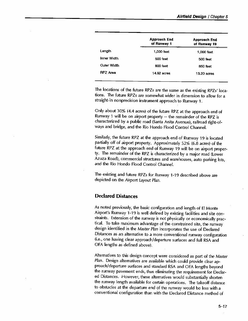
Airfield Design / Chapter 5
Approach End Approach Endof Runway 1 of Runway 19
Length 1 ,000 feet 1,000 feet
Inner Width 500 feet 500 feet
Outer Width 800 feet 650 feet
RPZ Area 14.92 acres 13.20 acres
The locations of the future RPZs are the same as the existing RPZs' loca-
tions. The future RPZs are somewhat wider in dimension to allow for astraight-in nonprecision instrument approach to Runway 1.
Only about 30% (4.4 acres) of the future RPZ at the approach end ofRunway 1 will be on airport propert - the remainder of the RPZ ischaracterized by a public road (Santa Anita Avenue), railroad right-of-ways and bridge, and the Rio Hondo Flood Control ChanneL.
Similarly, the future RPZ at the approach end of Runway 19 is locatedpartially off of airport propert. Approximately 52% (6.8 acres) of thefuture RPZ at the approach end of Runway 19 will be on airport proper-
ty. The remainder of the RPZ is characterized by a major road (Lower
Azuza Road), commercial structures and warehouses, auto parking lots,and the Rio Hondo Flood Control ChanneL.
The existing and future RPZs for Runway 1-19 described above aredepicted on the Airport Layout Plan.
Declared Distances
As noted previously, the basic configuration and length of EI MonteAirport's Runway 1-19 is well defined by existing facilities and site con-straints. Extension of the runway is not physically or economically prac-ticaL. To take maximum advantage of the constrained site, the runwaydesign identified in the Master Plan incorporates the use of DeclaredDistances as an alternative to a more conventional runway configuration(i.e., one having clear approach/departure surfaces and full RSA andOFA lengths as defined above).
Alternatives to this design concept were considered as part of the MasterPlan. Design alternatives are available which could provide clear ap-proach/departure surfaces and standard RSA and OFA lengths beyondthe runway pavement ends, thus eliminating the requirement for Declar-ed Distances. However, these alternatives would substantially shortenthe runway length available for certain operations. The takeoff distanceto obstacles at the departure end of the runway would be less with aconventional configuration than with the Declared Distance method of
5-17

Airfield Design / Chapter 5
determining runway length. Also, the published runway length would besubstantially less if a conventional layout were to be used.
Landing Threshold Displacement
The landing thresholds are shown on the Airport Layout Plan as beingdisplaced approximately 290 and 641 feet from Runway 1 and 19 pave-ment ends, respectively. This threshold configuration has existed at EIMonte Airport for many years. The siting of these Displaced Thresholdswas established at some point in the past, undoubtedly to provide for20:1 Approach Surface clearance over obstructions.
The Master Plan recommends that the current locations of the DisplacedThresholds be maintained throughout the 20-year planning period. This
recommendation is based upon the following factors:
· The current Displaced Threshold locations provide a clear 20:1Threshold Siting Surface.
· The current Displaced Threshold markings were recently repaintedand are in very good condition.
· Changing the threshold locations would require repositioning thethreshold lights, REILs, and visual glide slope indicators.
· The current Displaced Threshold locations have been well esta-blished by historic use and are accepted by the Airport's usergroup.
· The current Displaced Threshold locations are consistent withpresent and future operational needs.
· The current Displaced Threshold locations have the added benefitof reducing aircraft noise and overfight impacts - particularly tothe nort of the airport,
· There has been no significant demand for altering the location ofthe current Displaced Thresholds.
It should be noted that, with the removal of certain obstructions withinthe approach/departure surfaces, the displacement of the runway thresh-olds could be reduced or eliminated. However, for the reasons listedabove, this course of action is not believed to be necessary or desirableat this time.
5-18

Airfield Design / Chapter 5
The dimensions and characteris-tics of Threshold Siting Sunacesare described in Advisory Circular150/5300-13, Appendix 2).
At EI Monte Airport, RSA stan-dards and departure end obstruc-tion clearance requirements deter-mine the applicable Declared
Distances.
With the runway thresholds displaced as at present, the appropriateThreshold Siting Surfaces (TSS) clear all known objects on the ap-proaches to both Runway 1 and 19. The TSS appropriate to EI MonteAirport's Runway 1-19 is Runway Type "B." The TSS"begins at the Dis~placed Threshold where it is 250 feet wide and flares upwards and awayfrom the runway threshold at a 20:1 slope. The lateral dimensions of theTSS are somewhat less than the dimensions of the RPZ. The TSS aredepicted on the Approach Zone Plan.
ResuUant Runway Lengths
The physical length of EI Monte Airport's Runway 1-19 pavement is3,995 feet. This is the length of runway pavement that appears onaeronautical chart and other flght information publications. As noted
previously, however, this full length is not usable for all takeoff andlanding operations, The application of Declared Distances is required toadjust the length of runway available for specific types of operations.
A key factor in the calculation of Declared Distances is the location ofcontrollng departure end obstructions. There is no FAA airport designrequirement for a specific clear slope to be provided beyond the depar-ture end of a runway. FAA design standards do not formally define adeparture end surface in the manner that an approach end surface isdefined. The full length of a runway pavement can be considered usablefor takeoff even if a tall object exists immediately beyond the runwayend. Although not required, FAA guidance allows for the establishmentof departure end surfaces and RPZs at a location other than the runwayend. Establishment of departure end surfaces and RPZs at EI MonteAirport is, in the Consultant's view, warranted and appropriate.
Accordingly, the Master Plan recommends that the runway lengths becalculated on the basis of providing a clear 20:1 departure surface overimmovable departure-end obstructions. Moving the departure surfacesand RPZs inward to clear such obstructions will reduce the TakeoffRunway Available (TORA) as indicated below.
The controllng factors for locating EI Monte Airport's respective runwaydeparture surfaces and RPZs are as follows:
· For the departure surface and RPZ at the departure end of Run-way 1, a building obstruction light located 319 feet above MeanSea Level (Obstruction #15 - see Approach Zone Plan). Thisbuilding is considered to be an immovable obstruction of thedeparture surface.
· For the departure surface and RPZ at the departure end of Run-way 19, the physical end of runway pavement (plus 200 feet).
5-19

Airfield Design / Chapter 5
There are numerous other obstructions that currently penetrate theproposed departure end surfaces. However, it appears that all of theseobstructions can be removed or otherwise mitigated (i,e., topping oftrees, relocation of light standards, etc.). The proposed disposition ofthese obstructions is indicated on the Airspace Plan. For master planningpurposes, it is assumed that these "other" obstructions wil be removedor otherwise mitigated by the Airport owner prior to offcial publicationof Declared Distances data. Failure to address these obstructions couldresult in further reductions in the Declared Distances.
It should be recognized that 20:1 is a somewhat arbitrary slope withregard to aircraft departures. Unlike approach profiles which can berelatively consistent from aircraft to aircraft, especially where there isvisual or instrument guidance, departure profies are highly dependentupon aircraft performance (which is affected not only by aircraft type,but also by pilot technique, takeoff weight, wind, and air temperature).Considering the type and nature of aircraft operations at EI Monte Air-port, a 20:1 slope for the departure end surfaces appears reasonable.
Calculation of Declared Distances
The Declared Distances applicable to EI Monte Airport are describedbelow and indicated on the Airport Layout Plan. Following FAA approvalof the Airport Layout Plan and removal/mitigation of the noted obstruc-tions, this Declared Distances data will be included in the FAA's Air-port/Facility Directory.
· The Takeoff Runway Available (TORA) is defined as "the distanceto accelerate from brake release to lift-off, plus safety factors". AtEI Monte Airport, it is limited by the repositioning of the Runway 1departure surfaces and RPZs, The distances are 3,505 feet forRunway 1 and 3,995 feet for Runway 19.
· The Takeoff Distance Available (TODA) is defined as "the distanceto accelerate from brake release past lift-off to start of takeoffclimb, plus safety factors." In the proposed EI Monte Airport de-sign, TODA would equal the runway pavement length (i.e., 3,995feet) for both runway directions.
· The Accelerate-Stop Distance Available (ASDA) is "the distance toaccelerate from brake release to V1 and then decelerate to a stop,plus safety factors". The ASDAs for EI Monte Airport are 3,755feet for Runway 1 and 3,995 feet for Runway 19. The Runway 1ASDA is limited by the substandard RSA length at the departureend of the runway.
· The Landing Distance Available (LDA) is "distance from the thresh-old to complete the approach, touchdown, and decelerate to astop, plus safety factors". This is calculated as the runway length
5-20

Airfield Design / Chapter 5
minus the threshold displacement distance minus the substandardRSA length at the departure end of the runway. This works out to3,465 feet and 3,354 feet, respectively, for Runways 1 and 19,
Although these distances are somewhat less than the currently published.length of 3,995 feet for the existing runway configuration, it should beemphasized that the real difference is "truth in packaging." Being arelatively new runway design and operational consideration, very fewairport have determined, much less published, applicable DeclaredDistances data for their runways.
Implementation of these Declared Distances at EI Monte Airport will notrequire the remarking of the runway ends. However, the runway lightson the departure ends of Runway 1 and 19 should be modified to showthe appropriate advisory colors during night operations.
Although not required by the FAA, we recommend that informationalsigns advising departing pilots of these Declared Distances be postednear the respective runway entrance taxiways.
Building Restriction Lines
Building Restriction Lines (BRLs) identify suitable locations for airport
buildings and other stationary structures. The FAA Airport Design Ad-visory Circular no longer establishes standard setback distances or BRLs,
Rather, the FAA recommends that the BRL encompass the runway OFA,RPZs, areas required for airport traffc control tower clear line-of-sight,and navigational aid critical areas.
At EI Monte Airport, the east side BRL for Runway 1-19 has historicallybeen established 300 feet from the runway centerline. This distancereflects an old FAA standard. As depicted in Figure 5C, this 300-footBRL encompasses the Runway 1-19 OFA and adequately protects thoseareas required for airport traffc control tower line-of-sight and naviga-tional aid critical areas. This 300-foot BRL would permit a 25-foot-highstructure to be sited at the BRL without penetrating the existing FAR Part
77 7:1 transitional surface. The 300-foot BRL does not fully protect theFAR Part 77 7:1 transitional surfaces associated with the future Runway1-19 Primary Surface. In this future case, a 500-foot-wide Primary Sur-face is specified for runways with straight-in nonprecision instrumentapproaches. However, due to the presence of numerous existing struc-tures (e,g., aircraft hangars, control tower, and apron light towers), it isreasonable to continue to utilize the 300-foot BRL. Structures penetrat-ing the transitional surfaces associated with the future 500-foot-widePrimary Surface may need to have obstruction lighting. It is recom-mended that the 300-foot BRL setback distance be maintained along theeast side of Runway 1-19 into the future.
5-21

Airfield Design / Chapter 5
Due to the absence of buildings, structures, and developable areas onthe west side of the runway, a BRL is not formally designated for thisportion of the Airport. In addition, the presence of the Rio Hondo FloodControl Channel effectively precludes incompatible development in thisarea.
Blast Pads
Runway blast pads provide blast erosion protection beyond runwayends. While useful on all runways, blast pads are particularly beneficialon runways used by jet and large propeller-powered aircraft.
At the present time, there is no blast pad at either end of Runway 1-19.Due to the infrequent use of the Airport by jet and large propeller-pow-ered aircraft, no blast pads are required or depicted on the Airport Lay-out Plan.
AIRFIELD PROPERTY ACQUISITIONREQUIREMENTS
The FAA provides relatively little guidance regarding the appropriateminimum amount of propert an airport should own around the majorairfeld features. The practical criterion is that the airport should ownany propert on which the private propert owner's use of the propertis so restricted as to be of no value in private ownership.
Runway Protection Zones andApproach/Deparure Sunaces
The FAA strongly encourages airport operators to own, in fee-simple, allpropert located within approach/departure RPZs. Where fee-simple
ownership is not practical, easements may suffice. Over the years, theCounty has endeavored to acquire the land within EI Monte Airport'stwo RPZs. However, due to the extensive development and compatibleuse of this off-Airport land, acquisition of the entire RPZ areas has notbeen feasible nor is it necessary at this point.
While it is desirable to clear all objects from the RPZ, some uses arepermitted, provided they do not attract wildlife, are outside of the run-way OFA, and do not interfere with navigational aids. For example, golfcourses (but not club houses) and agricultural operations (other thanforestry or livestock farms) are expressly permitted under this proviso.Automobile parking facilities, although discouraged, may be permittedprovided the parking facilities and any associated appurtenances, inaddition to meeting all of the preceding conditions, are located outsideof the OFA extension. Land uses prohibited from the RPZ are: residen-
5-22

Airfield Design / Chapter 5
Q¡ca §1J .cÕUI1Ja gQ:G:
Q¡ca g1J .cÕUI1J.Q giiG:
",,0o c;; "-""-c ~;;~",g EJ:'C:J "a. a.
",,0o c;; "-""-c ~;;~,g Ë.."L::J "a. a.
Primary Surface250' '"c
;;a1J"F
OFA250'
-..eo.~ cß4: (,0
s"&
,"",o~c,'
.((c~1'.' Existing
T-Hangars
r- RSA -l
I r';;'ii
--.
L175o
~I: 220'& 300'
--a.4:
--iia:
45'
Existing Conditions
ARC B-11Small(NP11Circce-to-Land)
Primary Surface500'
OFA250'
'"c;;o
"0CDF
r- RSA -l
i r':ll--U
--U'
l-175~I 220'& : 300'
~ a.c.!;~ x00a. t-
--a.4:
--iia:
45'
Future Conditions
ARC B-11Small(NPI/Straight-in ;; 3/4 mile)
SCALEHorizontal - 1: 100
Vertical - 1: 20
Figure 5C
Runway Lateral DimensionsEI Monte Airport
5 - 23

Airfield Design / Chapter 5
ces and places of public assembly, churches, schools, hospitals, offcebuildings, shopping centers, and other uses with similar concentrations ofpersons typifying places of public assembly.
Where it is determined to be impracticable for the airport owner toacquire and plan the land uses within the entire RPZ, the FAA's RPZ
land use standards have recommendation status for that portion of theRPZ not controlled by the airport owner.
In the specific case of EI Monte Airport, the established land uses locat-ed on private and government propert within the RPZs are substantiallycompatible with Airport operations. No change in these land uses is an-ticipated. Neverteless, it is recommended that the Airport continue inits effort to gain effective and appropriate control over the land areasdefined by the RPZs. Such control, ideally, would be in the form of fee-simple propert acquisition by the Airport. Since this may be imprac-tical, an acceptable alternative would be to acquire avigation/approachprotection easements for some or all of the subject propert,
The County already has one such easement over private warehousing/commercial propert located between Lower Azuza Road and the Rio
Hondo Flood Control ChanneL. This existing easement is depicted onthe Airport Layout Plan.
Recommended propert/easement acquisition and related land usecontrol issues are further discussed in Chapter 7 - Land Use and En-vironmentallssues.
Adjacent to the Runways
Adjacent to runways, the minimum amount of airport propert shouldencompass the runway and taxiway OFAs. Preferably, it should alsoinclude propert on which objects of normal height would penetrate the
FAR Part 77 approach and transitional surfaces.
For runways designed to ARC B-I/Small standards (i.e., Runway 1-19 -existing and future), the OFAs extend 125 feet laterally from the runwaycenterline and 45 feet laterally from a parallel taxiway centerline. TheFAR Part 77 transitional surfaces begin at the outer edge of the OFA(also the Primary Surface in this case) and slope upwards 1 foot for each7 feet laterally. For example, a 20-foot-tall building or tree thus wouldrequire an additional 140 feet of setback distance beyond the OFA/PSAwidth to remain below the overriding 7:1 transitional surface.
The area immediately to the west of the runway is fully developed. It isunlikely that any further off-airport development wil occur in this areathat would significantly impact Airport operations. Similarly, on theAirport's east side, it is unlikely that any development will occur off ofAirport propert that would significantly impact airport operations.
5-24

Airfield Design / Chapter 5
The FAA defines a taxiway as adesignated path established forthe taxiing of aircraft from one partof an airport to another. A taxilaneis that portion of the aircraft park-ing area used for accss betweentaxiways and aircraft parking poi-tions. Typically, taxilanes offer
less clearance than taxiways.
Neverteless, it is recommended that the County maintain a high level ofvigilance to ensure that all proposed off-airport development penetratingthe Airport's FAR Part 77 surfaces is properly considered by the FAA andappropriately addressed.
TAXIWAY SYSTEM
Proposed Improvements
EI Monte Airport is well-served by its existing taxiway system. The re-cent extensive resealing and remarking of the Airport's paved surfacessubstantially enhances the operational safety, effciency, and appearanceof the Airport.
The centerline of the full-length parallel taxiway serving the east side ofRunway 1-19 is currently located 175 feet from the runway centerline.This value exceeds the 150-foot minimum dimension recommended bythe FAA for an ARC B-I/Small facility. In light of the Airport's wider-than-average runway (i.e., 75 feet actual versus 60 feet minimum recom-mended) and the Airport's somewhat unusual, but highly effective, pavedcontinuous drift-off area, this greater than FAA-recommended minimumdistance is appropriate and should be retained.
Taxiway Widths
The width of the parallel taxiway serving Runway 1-19 is 40 feet, andthe widths of the tiedown apron/T-hangar/FBO access taxiways aregenerally 40 feet as welL. These taxiway widths are somewhat greaterthan current FAA design standards which specify a 25-foot-wide taxiway
for ARC B-I/Small facilities. This greater taxiway width facilitates theoccasional passing of aircraft on the taxiways.
Aircraft Parking Limits
The appropriate setback distances from taxiways to fixed or movableobjects or to an Aircraft Parking Limit (APl) line is based primarily uponthe size of aircraft intended to use the facilities. In the case of ARC B-I/Small facilities, the distance between the taxiway centerline and fixedor movable object should be a minimum of 45 feet. It is recommendedthat the ARC B-I/Small distance of 45 feet be applied as a minimum toall taxiways on the Airport.
The location of the APL along a runway is usually dictated by the APL'srelationship to an adjacent parallel taxiway. The location of the APL is
5-25

Airfield Design / Chapter 5
determined by the application of the above-noted setback distances.On the parallel taxiway side of a runway (i.e., on the east side of Run-way 1-19) the APL should be located a minimum of 45 feet from thecenterline of the parallel taxiway. The current APL at EI Monte Airport islocated 60 feet from the centerline of the parallel taxiway. To accom-modate occasional use by aircraft that are larger than ARC B-I/Small, it isrecommended that this 60-foot setback be retained.
The appropriate setback distance from a taxi lane to fixed or movableobjects or to an APL should be a minimum of 40 feet.
Holding Bays
Also known as run-up areas, holding bays provide a standing space forairplanes (1) to test their engine(s) and equipment immediately prior totakeoff, and (2) to wait for an opportunity to fit into the aircraft arrival/departure stream. EI Monte Airport's Runway 1-19 is well-served byappropriately located and sized holding bays - one at each runway end.A recent improvement to these holding bays was the painting of direc-tional arrows on the ground to identify appropriate aircraft run-up orien-tation. This action reduced the noise, prop blast, and debris impactingadjacent FBO and aircraft operational areas. No change in the configur-ation or positioning of the holding bays is required or desirable.
OTHER AIRFIELD DESIGN ELEMENTS
Helicopter Operations
Five light helicopters are currently based at EI Monte Airport. Thesehelicopters, primarily R-22s, are parked throughout the airport buildingarea and are used primarily for flght training purposes. These basedhelicopters access the runway area for takeoff/landing by hover-taxiing
through the aircraft parking aprons and taxilanes. While not necessarilya desirable routing, this procedure represents a reasonable operationalcompromise that reflects the Airport's constrained layout and availablefacilities.
EI Monte Airport also sees occasional operations by light-to-medium-sized transient helicopters (e.g., Robinson R-22s, Bell Jet Rangers, etc.).In addition, large transient military helicopters (e.g., CH-47 and UH-1)occasionally utilize the Airport for refueling. Due to the relatively infre-quent need to accommodate such helicopters, a formal helipad has notbeen established on the Airport. Five helicopter parking positions areidentified on the old Airport Layout Plan some 150 feet southwest of the
5-26

Airfield Design r Chapter 5
aviation fueling island. Each of these five positions is marked with alarge painted "H" surrounded by a dashed triangle.
To facilitate current and future helicopter operations at the Airport,particularly transient helicopter operations, it is recommended that ahelicopter landing/takeoff target pad (helipad) be designated adjacent tothe transient helicopter parking area. A location mid-field on the paralleltaxiway appears to be the best compromise for siting the pad, This siteis depicted on the Airport Layout Plan. From this pad, helicopters would
hover-taxi a short distance to/from the designated transient helicopterparking positions located immediately to the southwest of the fuelingisland. It is anticipated that the operators of small helicopters based at EIMonte Airport wil continue to operate directly to/from their respectiveon-airport facilities.
Future decreases in demand for airplane tiedown facilities could result inmore apron becoming available for development of a dedicated helicop-ter operations area on the Airport. In this event, a portion of the unusedairplane tiedown area could be developed for dedicated helicopteroperations. Due to the uncertainty of such a scenario, a specific layoutfor this area/use has not been identified on the Airport Layout Plan.Such an area, however, should be located near suitable helicopter-ori-ented hangar/offce facilities and should be located so as to minimizehelicopter/airplane operational interaction.
Runway Lighting, Visual Approach Aids, and Marking
Runway 1-19 is equipped with Medium-Intensity Runway Lights (MIRL)which are in fair condition. Replacement/rehabiltation of the MIRLsystem will be needed within the next 5 to 10 years. Due to the uniqueoperational nature of EL Monte Airport's paved continuous drift-off area,the MIRL locations are visually highlighted with a 4-foot diameter disc ofwhite paint located at the base of each light. To further enhance theconspicuousness of these light stanchions to pilots exiting the runwayafter landing, particularly in daylight conditions, it is suggested that asmall, highly-visible, frangible cone could be placed over each lightstanchion. A small plastic reflective-surface traffc cone might be readilyadapted for this purpose. FAA concurrence should be obtained beforethis visual enhancement is installed.
A Visual Approach Slope Indicator (V ASI-V2L) with an approach slopeangle of 4.950 and a threshold crossing height of 64 feet serves theapproach end of Runway 1. A Visual Approach Slope Indicator (V ASI-V2R) with an approach angle of 4.500 and a threshold crossing height of37 feet serves the approach end of Runway 19. When the obstructionsin the approach/departure surfaces are mitigated, it is recommendedthat the need for these greater-than-normal V ASI approach slope anglesbe reevaluated. This reevaluation process should also consider the effectthe greater-than-normal V ASI approach slope angles have on reducing
5-27

Airfield Design / Chapter 5
aircraft noise impacting the residential areas underlying the runwayapproaches.
Runway 19 is equipped with Runway End Identification Lights (REILs).For the future, it is recommended that the approach end of Runway 1also be equipped with REILs. REILs on the approach end of Runway 1will greatly assist pilots in visually identifying the runway threshold duringmarginal visual or instrument meteorological conditions. These REILs will
be of particular value when the proposed straight-in nonprecision instru-ment approach to Runway 1 is implemented.
Runway 1-19 is marked as a Basic/Visual runway. Repainted in late-1993, these markings are in very good condition. In anticipation of afuture enhancement to EI Monte Airport's instrument approach capabili-
ty, it is recommended that these markings be upgraded to Nonprecisiontype markings when the runway is next repainted.
A painted 1 DO-foot diameter segmented circle with traffc pattern direc-tion indicators is located near the center of the runway/parallel taxiwaysystem. The traffc pattern direction indicators depict a left traffc patternfor Runway 1 and a right traffc pattern for Runway 19. Repainted inlate 1993, these markings are in very good condition.
The name "EL MONTE" is painted in 20-foot-high white letters immediat-ely nort of the segmented circle. This large marking aids pilots in visu-ally identifying the Airport. The markings are in good condition andserve a useful purpose. '
Taxiway Lighting and Marking
The full-length parallel taxiway serving Runway 1-19 is equipped with anin-pavement flush-mounted centerline lighting system. Due to its olderdesign and aging components, this system is costly to operate and main-tain. It is suggested that when the airfeld's lighting systems are nextrenewed, this centerline lighting system be replaced by more modernstate-of-the-art centerline lighting equipment.
All of the airfeld's taxiway markings were repainted in late 1993. Aspart of this project, the edge stripes delineating both outer limits of theparallel taxiway were repainted as double solid yellow stripes. Thismarking format is not consistent with current FAA marking standards.
Advisory Circular 150/5340-1 G Standards for Airport Markings (dated9/27/93) states that dashed taxiway edge markings are used when thereis an operational need to define the edge of a taxiway on a paved sur-face where the pavement contiguous to the taxiway edge is intended foruse by aircraft (e.g., an apron or drift-off area). The dashed taxiwayedge markings consist of a broken double yellow line, with each linebeing at least 6 inches (15 cm) in width, spaced 6 inches (15 cm) apart
5-28

Airfield Design / Chapter 5
(edge to edge). The lines are 15 feet (4.5 m) in length with 25-foot (7.5m) gaps.
Since aircraft are able to utilze (i.e" cross onto) the paved surfaceslocated on both sides of the parallel taxiway, dashed edge stripes areappropriate. Accordingly, it is recommended that the current solid taxi-way edge stripes be changed to dashed stripes.
Hold Lines
The FAA requires hold lines on all taxiways intersecting with runways.The hold lines at the two entrance taxiways serving Runway 1-19 arecurrently located 125 feet from the runway centerline. This is the ap- .propriate hold line setback distance for an ARC B-I/Small facility such asRunway 1-19.
Signing
EI Monte Airport is equipped with lighted runway/taxiway guidancesigning in accordance with FAA standards. In addition, supplementaladvisory and directional signing is provided throughout the airfeld andbuilding area.
Wind Indicators
The Airport is currently equipped with two wind indicators - a lightedwind cone near the Runway 19 touchdown zone (west side) and anunlighted supplemental wind cone near the touchdown zone of Runway1 (west side). These two wind cones provide adequate visual windinformation for EI Monte Airport's Runway 1-19. To further enhanceairport safety, it is suggested that a third wind cone be located at mid-field near the transient parking/future terminal area. A possible locationfor this third wind cone is above the aviation fuel dispensing island.
Automated Surface Observation Capabilty
As part of the National Weather Service's (NWS) nationwide program toenhance weather observing capability, EI Monte Airport is programmedto receive a NWS-funded Automated Surface Observation System(ASOS). This electronic system automatically senses current local weath-er conditions and report these conditions to pilots via aircraft radio andtelephone.
5-29

Airfield Design / Chapter 5
Basic ASOS provides wind speed, wind direction, temperature, dewpoint, and barometric pressure readings. More sophisticated systems
also register visibility, cloud height, and form of precipitation. The avail-ability of such a system at EI Monte Airport would substantially enhanceairport utility and facilitate safe aircraft operations.
EI Monte Airport's ASOS was originally programmed for installation inthe 1992-1993 timeframe. However, the installation schedule hasslipped and it is now thought that the system might be installed by early1995.
The ASOS siting team identified a location for the sensor array that isapproximately 300 feet norteast of the air traffc control tower - wherethe Civil Air Patrol offce trailer is currently located. This proposed loca-tion does not appear to be satisfactory - it is too shielded by surroun-ding trees and structures to accurately reflect airfeld wind/weatherconditions. As part of the Master Plan study, alternative sites for theASOS were explored,
The Master Plan analysis concluded that a more desirable site for theASOS sensor array would be on the west side of the Airport-near to theexisting wind sensor equipment. While not fully con-forming with theFAA's ASOS siting criteria, this location may represent the only availablesite for the ASOS on the Airport. This site is depicted on the AirportLayout Plan.
5-30

6
Building AreaDevelopment

6
Building Area Development
OVERVIEW
The building area of an airport encompasses all of the airport propertnot devoted to runways, major taxiways, required clear areas, and otherairfeld-related functions. Among the facilities found at most public-usegeneral aviation airport are:
· Based aircraft tiedowns and storage hangars.· Transient aircraft parking.· Fixed base operations facilities.· Fuel storage and dispensing equipment.· Public rest room(s).
· Aircraft washing area(s).
· Access roads and automobile parking.· Security/perimeter fencing and access gates,
· Lighting, marking, and signing.
· Public telephone(s).
Also common, particularly at busy public-use general aviation airport,are:
· Public terminaL.
. Air traffic control tower.· Emergency response equipment.· Corporate aircraft storage hangars/offices.· Airport maintenance facilities.· Tenant aircraft maintenance shelter(s).· Public airport viewing area(s).
· Aviation support facilities, such as restaurant/coffee shop, rental carfacilities, etc.
· Commercial/industrial buildings.
This chapter examines the factors which affect the siting and develop-ment of future building area facilities at EI Monte Airport and alternativeways of accommodating projected demand. The focus is on providing
6-1

Building Area Development / Chapter 6
direction for the appropriate expansion and use of the core building areaof the Airport. The various design and use issues associated with EI
Monte Airport's building area are graphically presented in Figure 6A.
DESIGN FACTORS
Many factors influence the planning and, later, the development deci-sions associated with EI Monte Airport's building area. Most of thesefactors can be grouped under six basic headings:
· Demand - The demand for additional building area facilities at EIMonte Airport is forecast to be modest over the 20-year planningperiod. This modest level of growth is typical of a community-orient-ed, primarily general aviation airport. As documented in Chapter 4,based aircraft are forecast to increase less than 10% - from thecurrent 475 to 515 - by the year 2013. This relatively modest in-crease in demand can be accommodated within the currently avail-able building area.
· Setback Distances - The interior boundary of the airport buildingarea is determined in large part by the necessary setback distancesfrom the runways and major taxiways. As discussed in the precedingchapter, the following design criteria are recommended:
A minimum of 300 feet from the Runway 1-19 centerline to anyfuture buildings on airport propert (shown on the Airport LayoutPlan as the Building Restriction Line iBRL)),
A minimum of 45 feet from taxiway centerlines to aircraft parkingpositions (shown as the Airplane Parking Limit iAPL)),
· Existing Facilities and Leases - The Airport's entire building area islocated to the east of Runway 1-19. Within the above noted setbackdistances, virtually all of the available land area is developed for avia-tion use. Only a 32,000-square-foot parcel of land (presently anunpaved grassy area under lease to the adjacent FBO) in the east-central portion of the Airport is undeveloped. In addition, a five-acreparcel of undeveloped land is located on the southeast side of SantaAnita Avenue. This parcel has no aircraft access to the Airport'saeronautical areas.
The physical condition of the existing structures and other facilitiesrange from fair to very good. Most of the existing facilities are ex-pected to be usable for 20 or more years and are assumed to remainin place and fully functionaL. The present condition and use of thevarious building area facilities is described in Appendix A.
6-2

Building Area Issues / Chapter 6
Transient I VisitorParking
HelicopterOperationalAreas
Northeast ComerDevelopment
J '-
Additional StorageHangars
Restaurant I CoffeeShop
--dè..
§v'bo,!
q;~~
::J
Public TerminalBuilding
Tenant AircraftMaintenance Shelter
~.,......f ,~,;~iä"~' -: Use of Property
to 1,200~Fee
Figure 6A
Building Area IssuesEI Monte Airport
6 - 3

Building Area Development / Chapter 6
At the present time, there are a number of significant leaseholds at EIMonte Airport. Four fixed base operations (Lynn's Aircraft Engines,Bartlett Aviation, FA.S.T., and Valley Flight Center) constitute themajor aeronautical-related leaseholds on the Airport. Various smaller
aeronautical leaseholds (e.g., aircraft storage hangars and offce trail-ers) are also located on airport propert.
· Accessibility - An importnt design consideration is the ease of
access to individual portions of the building area from both the taxi-way system and public roads. At EI Monte Airport, the full-lengthparallel taxiway provides excellent access between the runway andbuilding area. Three public vehicular access points off Santa Anita
Avenue and one controlled vehicular access point off Emery Avenueprovide good ground access to the building area facilities (both pub-lic and private). Vehicular access to the air traffc control tower isavailable via a manually-operated gate off Emery Avenue.
· Land Acquisition Potential - An importnt consideration is the desir-ability of providing sufficient land for unforeseen future building areadevelopment needs. The area around EI Monte Airport is fully devel-oped. Only a very few land areas adjacent to the Airport wouldreadily lend themselves to airport-related expansion. Should there beunanticipated strong demand for new building area facilities, theAirport would be constrained in its ability to significantly expand thebuilding area.
· Development Staging - Another importnt factor in the preparationof a building area plan is the timing of future development. Theobjective is to have a plan that is flexible enough to adapt to changesin type and pace of facility demands, is cost-effective, and also makessense at each stage of development. Sometimes, the best locationfor facilities in the short-term may conflict with the optimum long-range plan.
BUILDING AREA FACILITY REQUIREMENTS
Aircraft Storage and Parking
The forecasts and demand/capacity analyses prepared for the MasterPlan indicate that if adequate storage facilities are constructed approxi-mately 515 aircraft could be based at EI Monte Airport by the year2013, Peak transient aircraft parking demand is expected to increasefrom 20 spaces to 30 spaces over this same period.
6-4
Building Area Development / Chapter 6
Hangars
There are 25 hangar structures at EI Monte Airport housing approxi-mately 275 aircraft. Roughly one-half of these hangars are currentlyowned by the County. The ownership of all privately owned hangars onthe Airport will transfer to the County at the end of their respectivehangar leases. As noted previously, it is anticipated that demand foradditional aircraft storage hangars at the Airport will increase in the yearsahead. The continued availability of reasonably priced storage hangars isone of the key factors encouraging growth of based aircraft at EI MonteAirport. It is suggested that future hangar development reflect: (1) userdemand; (2) physical siting and locational considerations and; (3) fundingresources.
There is suffcient land available within the existing building area toaccommodate development of the additional number of hangars re-quired to meet projected demand over the 20-year planning period. Itwould be most effcient to construct the first 30 hangar units (25 por-table T-type and 5 box-type or 8 portble T-type, a 17-unit T-hangar
building, and 5 box-type) in the norteast corner of the Airport. This
area is already paved, well-drained, offers utilities, and is committed tosimilar hangar use. A subsequent bank of T-hangars (1 building with 20to 22 units) could be located as depicted in Figure 6B - ProposedGeneral Layout of Building Area. Two possible locations for this T-han-gar building are indicated on the Building Area Plan.
The type and size of the hangars can best be determined through asurvey of potential hangar users. Aircraft type, airframe dimensions, the
nature of hangar use (i.e., aircraft storage only versus workshop capabili-
ty), facility siting considerations, availability of adequate utilities, (specifi-cally water and electricity), and market price largely determine the rangeof hangar types and sizes required to satisfy demand. Experience atmost general aviation airport suggest that mid- to large-sized individualbox-type hangars are highly preferred by users. T-hangars, whetherportable or fixed, are most effcient in terms of apron area utilization.The rectangular or box-type hangar units require more apron area forsiting and thus are more expensive to rent.
In part of the country where sun exposure is high (such as in the EIMonte area), shade hangars are popular. Shade hangars are basically T-hangars without doors or interior partitions. Shade hangars offer aircraftprotection from the deleterious weathering effects of the sun and rain atless cost than T-hangars or conventional hangars. In addition, shadehangars can be sited on existing asphalt apron areas without the needfor expensive concrete floors and extensive site preparation and, in mostcases, reimbursement of AlP-funded apron development costs. Shadehangars also present a somewhat less formidable visual appearance thando standard T-hangars. Shade hangar rental rates are typically less thanT-hangar rental rates but more than tiedown rental rates. Shade hangars
6-5

Building Area Development / Chapter 6
are a reasonable option for development at EI Monte Airport in place ofthe proposed new T-hangar structures.
The timing and type of hangar development should be based upon userdemand, funding resources, and overall airport development stagingrequirements. The hangar development plan must have suffcient flexibi-lity to adjust to actual future requirements. Sites should be identified formore hangar units than are expected to be required. In the interim,these undeveloped hangar sites can continue to be utilized for aircrafttiedowns,
Appendix G provides additional information regarding the developmentand financing of aircraft storage hangars on publicly owned airport.
Based Tiedowns
There are 285 fixed aircraft tiedown positions designated at the Airport.These positions are well located throughout the building area. At thetime of the Master Plan inventory (August 1993), approximately 175 (or61 %) of these tiedowns were in use,
As noted in Chapter 4, EI Monte Airport is projected to see a very mod-est increase in the number of based aircraft over the next 20 years (i.e.,an increase of 40 aircraft). It is anticipated that most of these basedaircraft wil be accommodated in new or existing aircraft storage han-gars. Future demand for based aircraft tiedowns is expected to decreasesomewhat as new storage hangars are constructed. Demand for basedaircraft tiedowns at EI Monte Airport is projected to decrease from 175positions in 1993 to 160 positions in 2013.
Transient Parking Positions
In addition, 30 transient aircraft parking positions are located immediate-ly to the north and south of the aviation fueling island. The 10 positionsto the south are configured as taxi-in/taxi-out positions for large (i.e.,twin-engine) airplanes. The 18 positions on the north side of the fuelingisland are configured for tail-to-tail parking of smaller airplanes. Fiveparking positions for transient helicopters are located immediately to thesouthwest of the fueling island.
The majority of short-term transient aircraft wil continue to utilize thetransient parking apron located adjacent to the aircraft fueling island. Asmall number of transient aircraft users wil park, with permission, at theAirport's various fixed base operator facilities.
It is anticipated that these 30 transient aircraft parking positions will besuffcient to meet future demand. If additional capacity is required, theadjacent based tiedown areas can be readily converted to transientparking positions.
6-6

Building Area Issues / Chapter 6
-- --~ (/ ~
VI (/ Zl- I- I-Z Z Z Z :::: :: :: :: OJ
t' r' i- ,. ~~ ~ ~ ~ (/
i(/ (/ (/ ii(/ è3ii ii ii ii
-- -- -- -- zøøøø--z z z z :z-- -- -- --:z :z :z :z xi i! i I 0l- I- I- CD
o t~Feet
c
/o
r
40
Figure 68
Proposed General Layout of Building AreaEI Monte Airport
6 - 7

Building Area Development / Chapter 6
Helicopter Parking
As noted previously, EI Monte Airport sees occasional transient opera-tions by light- to medium-size civil helicopters and large military helicop-ters. Since the need to accommodate such helicopters is so infrequent,a formal helipad has not as yet been established on the Airport. Five
transient helicopter parking positions are identified on the current AirportLayout Plan some 150 feet southwest of the aviation fueling island. Inaddition, an Airport fixed base operator, Universal Air Academy, utilizesan area on the apron immediately south of the main Airport entranceroad for the parking and operation of an R-22 light helicopter.
It is anticipated that helicopters wil continue to utilize the Airport asthey have in the past - avoiding the flow of fixed-wing aircraft andlanding/departing from the mid-field area. If demand for transient heli-copter parking positions increases substantially in the future, portions ofthe airplane transient parking area can be converted for helicopter park-ing use. The transient airplane parking positions displaced by this actioncan be relocated to unused based tiedown positions in the vicinity ofthe fueling island. Transient helicopters can be parked to the south ofthe aviation fueling island or on the periphery of the FBO areas. Inthese locations, the interaction of helicopter and fixed-wing operations isminimized.
Fixed Base Operations Areas
At present there are four fixed base operations (FBO) locations at EIMonte Airport. The FBO facilities and services occupying these loca-tions are briefly described in Appendix A.
The Master Plan anticipates that the four conventional hangars currentlybeing used for fixed base operations will continue to be used for thissame purpose throughout the 20-year planning period. Little or nosignificant expansion of FBO-related facilities is anticipated.
A fifth conventional hangar (approximately 5,250 square feet in size) islocated on the Airport immediately west of the air traffc control tower.This hangar is currently being used for private storage of aircraft. Shoulddemand warrant it, this hangar could be used for a small fixed baseoperation - possibly a helicopter-oriented enterprise, A significant
deficiency of this site is its poor public access. At the present time,there is no direct public vehicular access to the site other than through acontrolled-access security gate. However, it may be possible to over-come these limitations and utilize the hangar for a fixed base operation.Depicted in Figure 6C is one possible site layout for fixed base opera-tions use of this hangar.
6-8

Building Area Issues / Chapter 6
. /
I
RESIDENCES
/++
++
AVIATIONSUPPORT
(FUTURE)
ELECTRICALVAUL T
CAPTRAILER
Emery Avenue
"'-BOX HANGARS
(4 UNITS)
..(/I-
_ ----
r--- z1 I
::
I 1
QJ.-..J~ I ~ ~ ~ (/-- J -: I
(/ Uì (/ (/~ 0:l- I- I-0.. 0: (/ -:12(/1 z z 2 -: I- 0
- -: I- ~ ~ :: 02 z-- -- --
l:1z1 I" I" /' z~ -:Ir!:Ji .q i(' (' N I/'.. .. ..I w ~, I (' x
(/ (/ (/ I- '- 0I gs .. 1
Q: 0: 0: CD-- .q .q -:I t; I 0 üÜ2 2 Z
ì -- --ILL , -: .q -:,
I I I~
I i I I
, Il- I- l-
I ,0 100-- 1
--,
Feet
I
Figure 6C
Hangar Site LayoutEI Monte Airport
6 - 9
Building Area Development / Chapter 6
In addition, the 32,OOO-square-foot undeveloped grassy area located inthe east-central portion of the Airport building area readily lends itself foruse in support of fixed base operations. This area could simply bepaved and used to support fixed base operations, or a fixed base opera-tions hangar and apron could be developed on the site, This area ispresently under lease to the adjacent FBO. In any event, it is recom-mended that this area be reserved for future fixed base operations use.
Automobile Parking
Three paved automobile parking lots are located within the airport buil-ding area. These three lots should adequately serve the present andanticipated. public parking needs of the present and future FBOs, the
airport administration offce, air traffic control tower, and transient air-craft users. To reduce demand upon this area, based aircraft operatorsare permitted to park their vehicles in their hangars or in the vicinity oftheir tiedown location. These three auto parking areas are adequatelysized to accommodate anticipated future demand.
Fuel Storage/Dispensing Facilities
Bulk aviation fuel is currently stored in three underground tanks at onelocation on the Airport. These three fuel storage tanks are locatedbelow the aviation fueling island near the center of the Airport. The bulkaviation fuel storage and dispensing facilities are described in AppendixA.
Environmental Protection Agency (EPA) and California Environmental
Quality Act (CEQA) regulations require that spil prevention and leakdetection systems be installed on all underground tanks to guard againstground water contamination from possible fuel leaks. The existing fueltanks have been modified to comply with these standards. The presentcondition of the Airport's active bulk aviation fuel storage tanks is suchthat one of the tanks, a 15,OOO-gallon 100ll gasoline tank, is in anenvironmentally acceptable condition and the other two tanks, one20,OOO-gallon 100ll gasoline tank and one 20,OOO-gallon Jet A tank,
may need to be renovated or replaced within the next five years.
As part of this Master Plan, a number of alternative sites for the Airport'saviation fueling facilities were analyzed. Both underground and above-ground tank configurations were considered. This analysis concluded
that the existing site is optimum for both present and future operations.
For the future, it is suggested that the County consider installing creditcard-operated, self-service aviation fuel dispensing equipment at thefueling island. Self-service fueling capability is becoming increasinglypopular at airport, just as it is at automobile service stations. The con-
6-10

Building Area Development / Chapter 6
Terminal Building
EssenUal Fun~ions· Pilot/passenger waiting area
· Flight planning/weather brefing
facilities· Pubbic telephones (24-hour
accss)· Public rest rooms (24-hour
accss)· User directory (24-hour ac-
cess)· Water cooler/fountain· Nearby automobile parking
Other Fun~ions. Airport offces - operations
and management· FBO offces· Community meeting room
· Other offce/commercial space
· Restaurant/coffee shop/snack
dispensers· Pubbic airport viewing area
cept has become more practical and widespread with the advent of newfuel pumps which allow users to insert a credit card, thus eliminating theneed for an attendant. Self-service fueling capability also permits 24-hour fueling availability without the need for an on-site attendant. Someconcerns remain about the safety of such unattended facilities, however.These concerns will undoubtedly be resolved as more experience isgained.
Terminal Building
One of the building area facility improvements most frequently sug-gested by EI Monte Airport based and transient users is the need for apublic terminal building. There is no such facility on the Airport at thepresent time. Seventy-two percent of those Airport users responding tothe Master Plan questionnaire indicated that pilot facilities (e.g., waitingarea, flight planning facilities, rest room, etc.) at EI Monte Airport shouldbe improved or provided. Fort-four percent of the questionnaire re-spondees volunteered that a restaurant or coffee shop would encouragetheir increased use of EI Monte Airport.
The previous (1988) Airport Layout Plan for EI Monte Airport depicted aproposed site for a future terminal building located approximately 100feet west of the rotating beacon - adjacent to an existing conventionalhangar/offce. This site has been reserved over the past several years forthe development of a terminal building, and possibly, a restaurant/coffeeshop. The site is currently being used, on an interim basis, as the loca-tion for a helicopter flight training temporary offce and automobileparking.
As part of this Master Plan, this reserved site and a number of other.potential terminal building sites were analyzed. This analysis indicatesthat the reserved site is the optimum location for future development ofthe public terminal area and related facilities and services. The factorsconsidered in the selection of this location include:
· Terminal' area is readily visible to general public and airport users. "
· Terminal area is located adjacent to primary area access roads (e.g.,adjacent to Santa Anita Avenue). This location permits easy groundaccess.
· Terminal area is. centrally located adjacent to runway/taxiway system(i.e., adjacent to Runway 1-19 parallel taxiway and major interior
. taxi lanes). This location permits easy aircraft access and transientaircraft parking.
· Terminal area offers a good view of airfeld operations (particularlyfrom a second-floor restaurant vantage point).
6-11
Building Area Development / Chapter 6
· There is a substantial existing commitment to terminal developmentin the area (e.g., ground access, parking, etc.).
· Clear developable space is available for expansion.
· Airport operations and fuel dispensing personnel based in a terminaloffce would have a good view of the Airport's central operationalarea and would be located close to the fuel dispensing island and thetransient aircraft parking area.
· Utilities are readily available.
· Other sections of the Airport are either heavily committed to otheruses (e.g., permanent hangar structures), or do not lend themselves toterminal development and use (e.g., poor vehicular access).
The terminal building could be built and operated either by the Countyor through a public/private business partnership. The structure could beeither one floor or two floors, The second floor, with its high vantagepoint, would well lend itself as the location for a restaurant/coffee shop.The development of a restaurant/coffee shop is seen as a very highpriority by many Airport users. There are advantages and disadvantagesassociated with the development of an airport-oriented restaurant/coffeeshop. A generic discussion of airport restaurant issues and opportunitiesis presented in Appendix H. Local demand should dictate the scope andextent of on-Airport restaurant development.
It is anticipated that a terminal building of between 2,500 to 5,000square feet should be adequate to meet EI Monte Airport's basic aero-nautical service needs. The terminal building should, at a minimum,provide the "Essential Functions" noted above. Additional space wouldbe required if the building is to include a conference room, rental offcespace, or restaurant/coffee shop facilities. Space for these functionscould double or triple the total basic building size. Commuter airlineterminal facilities are not planned for EI Monte Airport.
The EI Monte Airport terminal building should be designed to be a focalpoint not only with regard to location, but also in appearance. An at-tractive building and landscaping that blend well with the community isimportnt. The proposed location for the building will allow it to beeasily visible from both the runway/taxiway system and Santa AnitaAvenue, thus reinforcing its status as the air transporttion gateway tothe EI Monte community.
6-12

Building Area Development / Chapter 6
Other Aircraft Servicing Facilities
Aircraft Wash Rack
The Airport's aircraft wash rack is located approximately 500 feet south-east of the aviation fueling island. This facility is provided to the airporttenants without charge. The wash rack, which is equipped with a three-compartent clarifier and a rain diversion system, meets CEQA/EPAenvironmental requirements. Centrally located on the Airport, this siteappears to be satisfactory. No change in location is required or desired,
To better serve the Airport's based aircraft users, it may be desirable toprovide a second aircraft wash rack in the nortern portion of the Air-port. Water and sewer lines are available in this area of the Airport topermit development of a second wash rack. A possible site for thisfacility is depicted on the Airport Layout Plan.
Tenant Aircraft Maintenance Shelter
In an effort to provide enhanced tenant amenities and control unauth-orized aircraft maintenance in aircraft storage hangars and tiedownareas, some airport have constructed dedicated structures for tenantaircraft maintenance. The structures, commonly referred to as tenantaircraft maintenance shelters, typically consist of a one- or two-bay, all-metal, three-sided structure equipped with electrical power, work bench/vice, overhead lighting/skylights, fire protection, waste oil disposal tank,and, in some cases, compressed air. In addition, the structure should beconnected to an appropriate waste water recovery system and should
be readily visible to airport operations/security personneL.
The purpose of these shelters is to permit airport-based users and ten-ants to work on their own aircraft (in accordance with Federal AviationRegulation Part 43) in a safe, convenient, and controlled facility. Typical-ly, there is no charge to the based tenant for using the shelter to main-tain the tenant's private aircraft.
At one time, the County provided a hangar unit in the 'T' row of han-gars for tenant aircraft maintenance. This hangar unit is now being usedfor the storage of Airport equipment and materiaL. Therefore, there is notenant aircraft maintenance shelter available on the Airport at the pres-ent time. In the event such a shelter is desired, it should be sited in anarea convenient to the based tiedown aprons and aircraft storage han-gars. A potential site for a 50' x 50' single-bay tenant aircraft mainte-nance shelter at EI Monte Airport is identified on the Building Area Plan
near the present aircraft wash rack. As an alternative, the maintenanceshelter could be located in the northeast corner of the Airport. How-ever, a disadvantage of this northeast location is that the hangar wouldnot be readily visible to airport operations/security personneL.
6-13

Building Area Development / Chapter 6
Civil Air Patrol Trailer
Squadron 21 of the Civil Air Patrol (CAP) maintains an offce trailer/stor-age facility at EI Monte Airport. The trailer, which is in poor condition, islocated 300 feet east of the air traffc control tower. While not con-sidered an optimum location for this facility, it is anticipated that theCAP will continue to operate out of this facility into the foreseeablefuture.
Public Access Roads
The Airport's building area facilities are publicly accessed via two pavedcity streets - Santa Anita Avenue and Emery Avenue. Three vehicularentrances to the Airport feed off these two streets - a public entranceopposite Bryant Road, a public entrance next to the rotating beacon,and a controlled access entrance off Emery Avenue. Additional lockedaccess gates are located along the Airport's perimeter fence.
Of the two public airport access points off Santa Anita Avenue, onlyBryant Road is signalized - turn lanes are provided at both access
points, however. Should ground traffc at the main airport entrance (i.e.,near the rotating beacon) substantially increase in the future, it may bedesirable to signalize or otherwise improve this important intersection.
Security Fencing and Gating
The entire Airport perimeter is enclosed with six-foot-high chain-linkfence. The existing perimeter fencing appears to be serving the Airportand its users well and is judged to be satisfactory both in terms of con-dition and location.
With the exception of the main Airport entrance gate (i.e., near therotating beacon), all gates are either manually locked or equipped withatttomatic controlled access equipment. The main Airport entrance roadis equipped with a manually-operated rollng vehicle gate. This gatemust be opened manually if access to the center of the Airport is desir-ed. It is recommended that, with the development of the new terminalbuilding, this gate be upgraded to an automatic controlled-access con-figuration. This type of gate will enhance the safety, security, and ef-ficiency of Airport apron operations.
The vehicular access gate serving the air traffic control tower parking lotis manually operated. It is suggested that this gate be converted to acode/card-operated controlled-access configuration to enhance safetyand security for parking lot users.
6-14

Building Area Development / Chapter 6
SUPPLEMENTAL AVIATION SUPPORT AREA
The propert comprising EI Monte Airport includes a five-acre parcel ofundeveloped land located on the southeast side of Santa Anita Avenue,a major community thoroughfare. Being separated from the Airport bySanta Anita Avenue, this parcel does not now nor wil it ever likely havedirect aeronautical (i.e., taxiway) access to the Airport itself. However,being so close to the Airport, the parcel could be developed in an air-port/aviation support role. In the absence of demand for such airport/aviation-related development, portions of the parcel could be developedin an appropriate manner that is compatible with Airport operations.The revenue generated through development of this parcel would beused to support the" continued operation and improvement of the Air-port.
Development Constraints
Potential use of this propert is significantly constrained, however, by acombination of both aviation-related and other, nonaviation factors.These constraints, as depicted in Figure 6D, include:
· Runway Protection Zone - The existing RPZ for Runway 1 encom-
passes the western 1.4 acres of the propert. The expanded RPZwhich would result from future establishment of a straight-in instru-ment approach would affect a total of about 3.0 acres. FAA stan-dards indicate that RPZs should be clear of all objects, especiallywhen the RPZ is under the control of the airport. Certin agricultural,limited outdoor recreational, and automobile parking activities maybe acceptable in the portion of the RPZ outside of the Runway Ob-ject Free Area (all of the propert in question lies outside of thisarea). Any uses involving buildings or more than 10 to 15 peopleper acre would be unacceptable for the RPZ -porton of the propert
and only small concentrations - 50 to 60 people per acre, maximum- would be acceptable on the remainder of the parceL.
· Noise Impact - Most of the propert is impacted by noise levels ofat least 65-CNEL from both the Airport and Santa Anita Avenue.Noise-sensitive uses should be avoided unless adequate sound in-sulation is built into the structure.
· Road Access - The primary point of access to the propert is viaSanta Anita Avenue, a major thoroughfare. The existing road medianwould preclude access to and from the south-bound lanes unless atraffc study indicates that left-turn lanes could be safely installed.Also, the number of access points probably wil need to be limited.
6-15

Building Area Development / Chapter 6
A secondary point of access to the propert is via St. Louis Drive. Itis anticipated that the City will require restrictions on the use of thisstreet for access to the propert.
· Parcel Shape and Topography - The parcel is roughly in the shapeof two triangles joined at a narrow point less than 70 feet wide. Theflatter, southern portion encompasses about 3,6 acres, most of whichlies within the ultimate RPZ boundaries. The northern portion risesaway from Santa Anita Avenue, although the strip adjacent to theroad is essentially leveL. The barely 1.4-acre size of this segmentlimits the choice of uses.
· Adjacent Residential Uses - The rear of a row of single-family resi-dences borders the entire eastern edge of the parceL. Developmentof the parcel should be compatible with this adjacent land use.
Potential Types of Development
Taking these constraints into" account, the following emerge as possibleuses for this propert. This list is not meant to be all-inclusive; it is onlyintended to indicate examples of types of uses which would be consis-tent with the constraints identified. Because of the different factorsaffecting the southern and northern segments of the propert, the poten-tial uses for each area are listed separately.
Southern Segment
Acceptable forms of land use for the southern segment of the propert
are quite limited because of the diffcult road access and the need forthe use to be a low-density, outdoor activity.
· Automobile Parking - Several types of automobile parking activitiesare conceivable for this area, including:- Overfow public parking for the nearby bus and light-rail transit
stations.- Rental car parking, provided that any buildings are located outside
the RPZ or, at most, only along the eastern edge of the futureRPZ.
- An automobile sales lot, again with the same limitations on build-ings.
· Nursery - A horticultural nursery is an example of a potentially ac-ceptable retail use for this area. Such a use would have very lowconcentrations of people and the minimal building area could belocated outside or on the edge of the RPZ..
6-16

Building Area Issues / Chapter 6'.'U.~'"--,.-' ~~._-. ,..."-
..
EXISTINGROAD MEDIAN
Q¡.:c:§!
"Z
~(/
.S;i.(/;;£rCi
I.~
RISINGTERRAIN
BUILDINGSPOSSIBLE0.6 ACRE
FUTURE RPZ
I
EXIS~NG RPZ
Metro~ 200----
Feet
Figure6D
Supplemental Aviation Support AreaDevelopment Factors
EI Monte Airport6 - 17

Building Area Development / Chapter 6
Nortern Segment
Possible uses for the northern segment include the above uses plus thefollowing:
· Single-Story Offices - A small offce building is probably the most
realistic use for this segment of the propert. Such an activity wouldinvolve relatively few people and the limited need to accommodatethe general public would make the diffcult road access less signifi-cant than a more public use.
· Light Industrial Use - Another possible use, similar to an offceactivity, would be a small shop of some type. Examples of such ause include ~oodworking, jewelry manufacture, or electronic equip-ment repair. The small size of the parcel is probably the major limita-tion with regard to this type of activity.
· Retail Sales - Some type of low-intensity retail sales also might bepossible for this area, although accessibility and the small parcel sizewould be constraints, An activity which could make outdoor use ofthe larger, southern segment would be the most practicaL.
· Mini-Storage - Another use which would be acceptable for thenorthern segment from an airport compatibility standpoint is a mini-storage facility. The 1.4-acre size of this area may not be largeenough for such a facility, however. The site could be slightly ex-panded by also placing additional buildings in the southern seg-ments O.6-acre sliver of land lying outside or on the edge of thefuture Runway Protection Zone.
BUILDING AREA LAND ACQUISITION
As mentioned previously, there is suffcient land available within thebuilding area to accommodate development of terminal area facilities,hangars, tiedowns, fixed base operations, specialty shops, and relatedaviation uses to meet current needs and anticipated aeronautical de-mand throughout the 20-year planning period. Should the building areadevelop as recommended, the Airport wil have utilized all of the landavailable for aeronautical uses, If possible, additional propert should beacquired to facilitate future airport-related commercial/industrial growt.
The Airport is landlocked by existing private development and publicfacilities on all sides except the northeast corner where there is a smallresidential neighborhood with a school (Mulhall Elementary). Expansioninto this area is not contemplated, but acquisition should be consideredif any of the parties came to the County with a land-sale proposaL.
6-18

Building Area Development / Chapter 6
From an economic development perspective, conversion of the largeschool parcel would offer the greatest opportunities. It has the advan-tages of one ownership, existing open space, and no dwellng units. Thiseight-acre parcel is located immediately norteast of the Emery Avenueairport entrance gate, and the parcel could be connected to the Airportwith taxiway access. Should this parcel become available on the openmarket, serious consideration should be given to its acquisition for air-port-support purposes. The acquisition of this parcel is discussed furterin Chapter 7 - Land Use and Environmental Issues.
6-19
1
Land Use
andEnvironmental Issues

7
Land Use andEnvironmental Issues
OVERVIEW
In some ways, land use compatibility issues are importnt factors at EIMonte Airport and, in other respects, they are of minimal concern. Theexisting intensive urban, and especially residential, land uses around theAirport are not what would normally be considered compatible with air-port activities. But, because the surrounding area is totally developed,there is little that can be done to significantly improve existing conditionsshort of major land use redevelopment or restrictions on airport activity.Also, despite the seemingly incompatible conditions, complaints from the10caVresidents about airport operations have been few.
The fact that compatibility has not been an issue is undoubtedly attribut-able to the limited nature of airport operations (predominantly light,general aviation airplanes), the busy, relatively noisy character of thesurrounding area, and the mutual understanding of each others concernsby pilots and area residents. Given this positive overall compatibiltystatus, it is not the intent of the analysis in this chapter to create an issuewhere none now exists. Rather, the purpose is to further promote anawareness of compatibility concerns and to identify actions which shouldbe taken - and ones which should be avoided - to prevent problems
from arising.
The following discussion examines noise and safety concerns typical ofgeneral aviation airport. The EI Monte Airport land use compatibility
issues addressed in this chapter center around these concerns. Thechapter's final section summarizes some of the other types of environ-mental impacts associated with the proposed development and use of EIMonte Airport.
7-1

Land Use and Environmental Issues I Chapter 7
As used here, measured noise isthe type of noise impact primarilydefined and measured by standar-dized, cumulative noise levelmetrics.
CNEL ContourCalculations Inputs
· The number of operations byaircraft type or group.
. The distribuon of operations
by time of day for each aircrafttype.
· The average takeoff profile andstandard approach slope usedby each aircraft type.
· The amount of noise transmitt-ed by each aircraft type, mea-sured at various distances fromthe aircraft.
· The runway system configura-tion and runway lengts.
· Runway utilzation distrbutionby aircraft type and time ofday.
· The geometr of common air-craft flight tracks.
· The distribution of operationsfor each flight track.
7-2
NOISE COMPATIBILITY
Noise is often described as unwanted or disruptive sound. Because ofits routine, everyday occurrence, it is usually perceived as the most sig-nificant adverse impact of airport activity.
Measured Noise
A pure sound is measured in terms of: its magnitude (often thought ofas loudness) as indicated on the decibel (dB) scale; its frequency (ortonal quality) measured in cycles per second (hert); and its duration orlength of time over which it occurs. To measure the noise value of asound or series of sounds, other factors also must be considered. Air-port noise is particularly complex to measure because of the widelyvarying characteristics of the individual sound events and the intermittent
. nature of these events' occurrence.
In an attempt to provide a single measure of airport noise impacts, vari-ous cumulative noise level noise metrics have been devised. The metricmost commonly used in California is the Community Noise EquivalentLevel (CNEL). Elsewhere in the United States, the similar Day-NightAverage Sound Level (DNL) metric is used. The results of CNEL or DNLcalculations are normally depicted by a series of contours representingpoints of equal noise exposure in 5 dB increments. Key factors involvedin calculation of CNEL or DNL contours are noted to the left.
The primary function of the contours produced by CNEL and DNL calcu-lations is to show areas affected by significant noise levels resulting fromhigh concentrations of aircraft takeoffs and landings. For this purpose,these metrics are considered to be the best tools available. Two limita-tions of cumulative noise level metrics are importnt to recognize, how-ever:
· Accuracy - Because of the number of assumptions usually involved
in the calculation inputs, cumulative noise level contours for generalaviation airport are regarded as having an accuracy of about:l3 dB(the accuracy is somewhat greater at airline airport because airlineaircraft are more consistent in the flght paths and procedures theyfollow and better data is usually available). Cumulative noise levelcontours do not encompass the total area affected by aircraft noisearound an airport. Use of noise contours to show marginally affectedareas is, at best, imprecise because of the varied distribution of air-craft flght tracks and altitudes which occurs with increased distancefrom the ends of runways.
· Averaging - The values produced by CNEL and DNL calculationseach represent decibel averages of the individual noise events andthe quieter periods between them. Because decibels are measured

Land Use and Environmental Issues I Chapter 7
As the term is applied here, anoverflight means any distinctlyaudibbe and usually visible pas-sage of an aircraft, not necessarilyone which is directly overhead.
on a logarithmic scale, the average is weighted in favor of the loudernoise events. Neverteless, cumulative noise level metrics do notdirectly measure either the peak sound levels of individual events orhow frequently the events occur.
Single-event overfight noise can be of particular concern at generalaviation airport, especially when a small number of operations bycertain aircraft may be distinctly louder than the majority of aircraftusing the airport. These occasional loud individual events are oftenthe principal cause of noise complaints from people living nearby.
Overfight Impacts
A general definition of overflight impacts is that they are noise-relatedimpacts which occur in the portions of an airport environs lying beyondthe typical contours measured by cumulative noise level metrics. Com-pared to the measured noise impacts, overfight impacts are more subtleand subjective. Also, they seem to include elements of both noise andsafety concerns. Often the impacts are revealed in the form of annoy-ance expressed by some people living near an airport.
Although overfight noise is detectible and therefore measurable, thehighly subjective individual reactions to overfights makes the value ofmeasurement on a decibel scale questionable. A more representativemeasure of overfight impacts is the absolute number of events whichoccur, but little is known about what an acceptable number might be.
For the purposes of airport land use compatibility planning, a simplerform of assessment may be more practicaL. This approach presumes thataircraft overfight impacts are potentially a concern anywhere along thestandard aircraft traffc pattern flight tracks. Concerns can also be ex-pected, but to lesser degrees, elsewhere in the airport vicinity where air-craft fly at or below traffc pattern altitude while approaching or depar-ting the runway. .
Whether a significant degree of overfight annoyance wil actually occurin the vicinity of an airport is influenced by a variety of factors, both en-vironmental and human. Building type and design, ambient noise levels,the characteristics and predictability of the noise itself, and (as notedabove) the frequency of occurrence are among the environmental fac-tors involved. An individual's sense of annoyance at overfights de-pends upon such factors as personal sensitivity to noise, attitudes towardaviation, and experience and expectations regarding noise levels in thecommunity.
7-3
Land Use and Environmental Issues I Chapter 7
Noise Compatibility Concepts
The basic approach to enhancing noise compatibility is to minimize theextent to which noise impacts disrupt human activities. Among thefactors in this equation are:
- The absolute loudness of the noises people hear;
- The relative loudness compared to background noise levels;- The frequency with which the noise events occur; and
- The types of activity affected.
Various studies have been done to ascertin the relationships amongthese factors. Typically, the results are formulated in terms of the cumu-lative noise levels acceptable or unacceptable for specific types of landuses. California State Aeronautics Law establishes a CNEL of 65 dB asthe maximum acceptable noise exposure for residential land uses. Part
150 of the Federal Aviation Regulations has a similar residential limit ofDNL-65. These criteria, however, are set primarily with regard to aircarrier airport in urban locations. For general aviation airport located
in comparatively quiet settngs, a CNEL or DNLof 60 dB is commonlyused. Neither the FAA nor the California Division of Aeronautics cur-rently have criteria relating the acceptability of single-event noise levelsto specific land uses.
As with measured noise impacts, the ideal strategy for limiting overfightimpacts is to avoid residential or other noise-sensitive development inaffected locations. To the extent that this strategy is not practical, themost useful approach is one which recognizes the subjective nature ofannoyance. From a land use compatibility policy perspective, this char-acteristic of annoyance suggests the importnce of educating the com-munity about the airport. Most importntly, if people are made awareof an airport's proximity and the nature and location of aircraft over-flights before moving into the airport area, the likelihood of them beingannoyed by the airport activity can be reduced. This objective can bestbe accomplished through some form of buyer awareness program as dis-cussed later in this chapter.
SAFElY COMPA TI BI LIlY
In examining safety factors in the vicinity of an airport, the primary con-cern is usually for the safety of people and propert on the ground. Thesafety of aircraft occupants is also an importnt consideration, however.In each case, the concept of risk is central to the assessment of safetycompatibility.
7-4

Land Use and Environmental Issues I Chapter 7
Safety on the Ground
A fundamental objective of airport/land use compatibility planning is toprovide for the safety of people and propert on the ground in the eventof an aircraft accident near an airport. However, because aircraft acci-dents are infrequent occurrences - particularly accidents occurringbeyond airport boundaries - determining how much risk exists and howmuch is acceptable are often diffcult questions.
Aircraft accident probabilities increase with closer proximity to the endof a runway. This increased risk to people and structures on the groundis largely due to the greater concentration of aircraft flying over theseareas. Additionally, the low altitude of the aircraft during final approachor initial climb contributes to the risk. The most critical areas are thelands immediately beyond the runway ends - the Runway ProtectionZones. Beyond these FAA-defined boundaries, the remainder of therunway approach zones plus other areas over which aircraft commonlyfly at low altitudes also have significant levels of risk.
Low flight altitudes present greater risks because they offer pilots lessopportunity to recover from unexpected occurrences or choice of whereto make an emergency landing if one becomes unavoidable. At alti-tudes less than 500 feet above the ground, only moderate turns areadvisable and the choice of emergency landing area is essentially limitedto what lies ahead. Above this altitude, recovery or at least a fairly widediscretion in choice of emergency landing sites is possible. An emergen-cy landing on the runway normally can be accomplished when the air-craft is flying in the traffc pattern at the typical traffc pattern altitude(800 to 1,000 feet).
Additional areas where the risks are above average are along the mostcommon flight tracks for aircraft approaching and departing an airport.Accidents occur relatively infrequently in these areas, however, and theprobability of occurrence in any given location is substantially less thanwithin the approach/departure corridors.
Safety of Aircraft Occupants
There are two facets to this safety concern: avoiding land use condi-tions that can become hazards to flight; and increasing the chances ofthe aircraft occupants' survival if an aircraft accident takes place beyondairport boundaries.
· Hazards to Flight - Land use conditions that can constitute hazards
to flight include airspace obstructions and visual or electronic inter-ference to -aircraft navigation or communication. Another type ofhazard to flight - bird strikes - is usually not a significant concern in
7-5

Land Use and Environmental Issues I Chapter 7
urban areas such as around EI Monte Airport unless large waterbodies or refuse disposal sites are situated nearby.
- Airspace Obstructions - The airspace needed for operation ofaircraft around an airport is defined by Part 77 of the FederalAviation Regulations (FAR) and by the U.S. Standards for Terminal
Instrument Procedures (TERPS). In most circumstances, the latteris the less restrictive set of criteria. Limiting the heights of struc-tures to the heights indicated by the Part 77 surfaces provides an
ample margin of safety for normal aircraft operations. The mostcritical locations with regard to the height of objects are thosewithin the runway approach zones.
- Visual and Electronic Interference - Most other land use charac-teristics that can affect flight safety fall into this category. Visualhazards include distracting lights (particularly lights which can beconfused with airfeld lights), glare, and sources of smoke. Elec-tronic hazards include any uses which interfere with aircraft instru-ments or radio communication.
· Limiting On-Board Injuries - In some respects, a concern over limit-ing on-board injuries in the event of an aircraft accident seems ir-relevant in that aircraft occupants (and particularly general aviationaircraft occupants) presumably accept the risk associated with flyingwhen they board the aircraft. Nevertheless, the precedent for landuse measures to enhance the survivability of an aircraft accident is setby FAA criteria for establishment of safety areas and object free areasadjacent to and at the ends of airport runways. Because a significantpercentage of aircraft accidents occur in locations beyond theseareas, as well as beyond the boundaries of runway protection zones,the availabilty of level, open land around an airport is an importntmeasure of the safety compatibility between an airport and its envi-rons.
Safety Compatibility Concepts
To a considerable extent, the concepts for providing safety for people onthe ground near an airport overlap with the approaches to enhancingsafety for occupants of aircraft. There are three basic land use ap-proaches to safety compatibility:
- Limiting the density of development;- Providing open areas for emergency aircraft landings; and- Limiting hazards to flight.
7-6

Land Use and Environmental Issues I Chapter 7
Typical light industrial uses, suchas the ones common to the EIMonte Airport vicinity, tend to aver-age around 50 people per acre, asdo two-story motels. Shopping
centers are likely to average about75 people per acre and restau-rants are often over 1 00.
Density of Development
A primary means of limiting the risks of injury to persons or damage topropert on the ground due to near-airport aircraft accidents is to limitthe density of land use development in these areas. The best measureof development density in this context is the number of persons peracre. The question of where to set these limits is dependent upon boththe probability of an accident and the degree of risk that the communityfinds acceptable.
Some airport and local communities have set development density limi-tations ranging between 25 and 100 people per net acre for variouspart of runway approach corridors. Many times these basic criteria aretranslated into a matrix indicating the acceptability or unacceptability ofspecific land use categories within various safety zones around an air-port.
Open Areas for Emergency Aircraft Landing
A high percentage of off-airport aircraft accidents and incidents involvecircumstances in which an engine malfunction forces an emergencylanding. In most such instances, it is possible for the pilot to maintaincontrol of the aircraft as it descends. When an emergency occurs whileapproaching or departng an airport, most pilots wil attempt to reach orreturn to that airport. If landing at the airport is not possible, the pre-
ferred choice usually is to head for the best available open space locatedsomewhere ahead - preferably landing into the wind. An open areadoes not have to be very large to enable a successful emergency landing- the objective is for the occupants to survive the accident with limited
injury; damage to the aircraft is irrelevant in these circumstances. Forexample, a 75-foot by 300-foot area (the size of a football field) can besuffcient for a survivable emergency landing in a small plane if the areais relatively level and mostly free of overhead lines and large obstaclessuch as trees and poles. Because the pilot's discretion in selecting anemergency landing site is reduced as the aircraft's altitude decreases,open areas preferably should be spaced more closely in those locationsoverfown at low altitude.
Preserving suitable open areas in the vicinity of airport is seldom aneasy proposition. Historically, little has been done in this regard aroundmost urban area airport, EI Monte Airport included. In more recentyears, greater awareness of this issue - as well as recognition of thesafety benefits of limiting land use density near airport - has led plan-ners to try to locate parks, golf courses, or even parking lots in the mostcritical areas around airport situated in urbanizing communities. To besuccessful, such effort usually must be made as part of a general planor specific plan process. Once an area has been divided into small par-cels, few opportunities to preserve open spaces remain.
7-7

Land Use and Environmental Issues / Chapter 7
Hazards to Flight
Hazards to flight - airspace obstructions, visual and electronic inter-ference, and uses which attract birds - frequently occur near airportsimply because a lack of awareness of the potential problems. Fortu-nately, the most significant of these hazards - tall structures which poseairspace obstructions - are the best recognized, thanks largely to Calif-ornia state airport regulations and the FAA's model height limit ordi-nance based on FAR Part 77 (Advisory Circular 150/5190-4A). Even so,potentially hazardous structures sometimes are built without proper noti-fication to and review by the FAA. It is thus importnt for communitiesnear airport not only to adopt local regulations regarding hazards to
flght, but also to make certin that their planners are aware of andenforce those regulations.
EL MONTE AIRPORT LAND USECOMPA 11BILITY STATUS
When viewed with respect to the general types of airport/land use com-patibility concerns described in the preceding paragraphs, a high degreeof incompatibility would seem to exist between EI Monte Airport and itshighly urbanized surroundings. The reality, though, is that the airportand its neighbors have coexisted rather well and problems have beenrelatively few. The focus óf the following discussion, therefore, is pri-marily on measures which should be considered to help prevent moresignificant compatibility problems from arising in the future.
The discussion begins with reviews of existing land use conditions andplans and of the Airport's existing and projected impacts. Specific pres-ent and potential future concerns are identified next. Finally, suggested
compatibility measures are outlined.
Existing Land Use Plans and Policies
As noted previously, all of the EI Monte Airport propert lies within theincorporated boundaries of the City of EI Monte. The San Gabriel Val-ley, though, is comprised of numerous small cities, several of which areaffected by airport traffic. Much of the traffic pattern on the nortwestside of the Airport crosses over the City of Temple City and, beyond adistance of 0.4 miles, the Runway 19 approach zone encompasses anunincorporated portion of the County of Los Angeles. Within two milesof the runway ends - an area within which aircraft are entering andleaving the traffic pattern - lie a significant piece of the City of Arcadia(north of the Airport) and smaller sections of the cities of Monrovia(northeast), Irwindale (northeast), South EI Monte (south), and Rosemead(west).
7-8

Land Use and Environmental Issues I Chapter 7
The establishment of ALUCs andthe preparation of airport land useplans are required by state law.ALUCs have responsibilties forthe review of proposed land usesin the vicinity of airports. Theyhave no authority over existingland uses or the operation of anyairport.
The principal guidance regarding the compatibility of land use develop-ment in the EI Monte Airport vicinity comes from two sources: theEI Monte General Plan and the Los Angeles County Airport Land UsePlan.
£1 Monte General Plan
The EI Monte General Plan was adopted by the City of EI Monte in July1991. BecaUSe the city has virtually no remaining vacant land, the landuse plan for the airport area predominantly reflects existing conditions.Industrial uses are emphasized within locations most affected by airportoperations.
The Noise Element of the General Plan specifically addresses airportnoise and includes several policies designed to minimize aircraft noiseimpacts on EI Monte residents. Among other things, these policiesencourage the use of "noise-reducing modifications to planes using EIMonte Airport" and the enforcement of "noise-attenuating flight proce-dures."
Los Angeles County Airport Land Use Plan
The Los Angeles County Airport Land Use Plan is a county-wide docu-ment adopted in December 1991 by the County Regional Planning Com-mission in its role as the Airport Land Use Commission (ALUC) for LosAngeles County. This plan pertins to EI Monte Airport as well as to 14other public-use airport within the County.
One function of airport land use plans is to define the boundaries of theareas considered to be affected by airport operations. Within theseboundaries, appropriate restrictions on land use development are set toassure compatibility with noise and safety criteria. Each ALUC establi-shes the policies for the airport within its jurisdiction. Among the com-patibility policies in the Los Angeles County plan are the following:
· For general aviation airport (including EI Monte Airport), the planindicates that the 60-to-65-CNEL range best represents the annoy-ance factor associated with smaller, but lower flying aircraft. (Notethat the compatibility plan currently shows only a 70-CNEL contourfor EI Monte Airport, but says that the plan will be amended whennew contours are obtained. It is anticipated that the new contoursprepared as part of this EI Monte Airport Master Plan will be adoptedby the ALUC for this purpose.)
· With regard to safety, the plan states that "no structure wil be per-mitted nor the congregation of people allowed" within Runway Pro-tection. Zones. Safety policies also prohibit various hazards to flight(obstructions, distracting lights, electrical interference, etc.) within theRPZs. Other than basic height restrictions in accordance with Part 77
7-9

Land Use and Environmental Issues I Chapter 7
New noise contours for EI MonteAirport were calculated as part ofthis Master Plan Report. A sum-mary of the data used in the cal-culations is presented in Appendixi.
7-10
of the Federal Aviation Regulations, no safety criteria are establishedfor locations beyond the RPZs.
· "... dedication of an avigation easement to the jurisdiction owning theairport as a condition of approval on any project within the designat-ed planning boundaries" is to be considered.
· ".. recycling of incompatible land uses to uses which are compatible
with the airport" is encouraged.
EI Monte Airport Impacts
Noise
The current (1993) and projected (2013) noise impacts generated byaircraft operations at EI Monte Airport are illustrated in Figures 7 A and
7B. The expansion of the noise contours over the 20-year time frame isattributable to the projected 13% increase in total operations plus aslight shift toward higher proportions of helicopters and twin-enginepropeller airplanes in the fleet mix.
The only residences within the existing 65-CNEL contour are some ofthe mobile homes located in the Daleview Trailer Park just beyond theRio Hondo channel north of the Airport (the relatively few noise com-plaints received by the Airport mostly come from this mobile homepark). By 2013, the projected 65-CNEL contour wil encompass a fewmore of the mobile homes and also wil just touch the residential area atthe end of St. Louis Drive south of the Airport (the latter area, it shouldbe noted, also lies within the existing 65 and future 70-CNEL contoursfor Santa Anita Avenue, according to the EI Monte General Plan NoiseElement). The 60-CNEL contour, both existing and future, includes thefirst row of homes along Whitney Drive across the channel to the west.For the most part, though, the area most affected by aircraft noise ateach end of the runway predominantly consists of commercial andindustrial land uses.
The median location of EI Monte Airport flght tracks is depicted inFigure 7C. The areas affected contain a mixture of urban land uses,although the majority are residentiaL.
Safety
As indicated in the general discussion earlier in this chapter, the loca-tions of greatest concern with regard to safety around airport are theRunway Protection Zones and immediately adjoining areas. Althoughthe Airport owns less than half of the land within each of the two futureRPZs, most of the remaining propert consists of road and railroadrights-of-way and the Rio Hondo flood control channeL. Only a portion
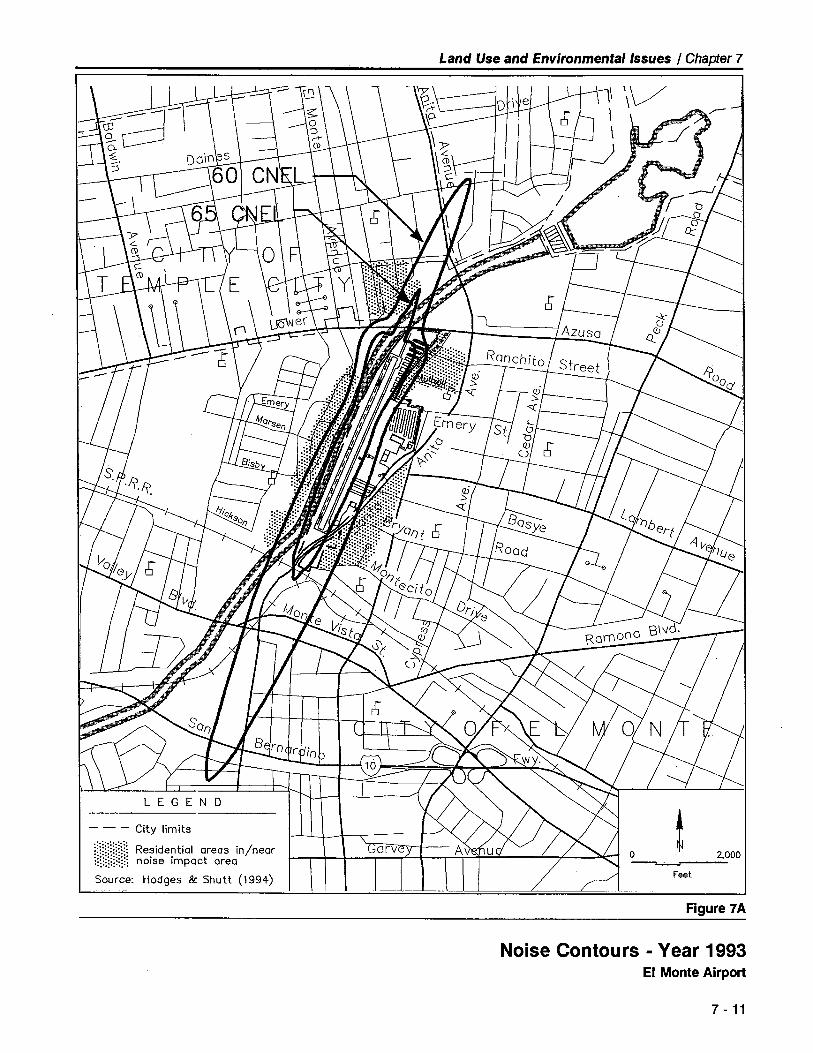
Land Use and Environmental Issues I Chapter 7
- - - City limits
(~?~~~~ Residential areas in/near
unu~ noise impact areaSource: Hodges & Shutt (1994)
~2,000
Feet
Figure 7 A
Noise Contours - Year 1993EI Monte Airport
7 - 11

Land Use and Environmental Issues I Chapter 7
- - - City limits
:~~~t:~~~~ Residential areas in/near
U~/H¡j noise impact area
Source: Hodges & Shutt (1994)
Figure 7B
~ 2,000
Feet
Nosie Contours - Year 2013EI Monte Airport
7 - 12

Land Use and Environmental Issues I Chapter 7
J \ CW \ \ I ~ i t= II = ii I "- I ì
t: ~ - 1 ' ~ .t~ L ~~ \ l-,- L.\.'' i---- \ I ò t- -\- . ~t.· if cS-- !I ).. --~ ~'j7~O
, "tÒ .lV-- -~lC ~ Q:
1 \ r~i-
L~Yj .:.
\~ ~òh c;
I~ ~' \
.\ AzusaQ.'l
r~ òRonc~ Roact
~ Ii '""J:
i~ c.6'" L --I~
~mery 51 71-0 ò 77
.... ; .~ ~"."
..0 -. u.0°" e,.yO ò .s
"UA t)t,;'1"" i ~ r¡
I- ,- Ò Ò 0'lt. . l?oaC/- - 00"0 ~- ~--lII ~j- ~ Iii
-4 rrr~
()..
J ~Ò.~ -.~ I
(,,\0" l---- F= 71. /) "' ~~ -A ~-- 7-0. '"ÒO I ..-...0" ~~I \. ~ lc ~ll
i-'o i i.. l.~1 \ i ..~,J if 7~I . ~ .. -,\)- - -.
r r- 1
~~ ~ /I-t
I)l- .. ~ )/
f- ~'f- i- , -- 0 3,000i- - -i- feet
I
\ \ -/ \
Traffic Pattern Altitude
Note: See Appendix I for percentage distribution of flight tracks. 1.296' MSL
Source: Hodges & Shutt (1994). (1,000' AGL)
Figure 7C
Airport Flight TracksEI Monte Airport
7 - 13

Land Use and Environmental Issues I Chapter 7
of one building - adjacent to Lower Azusa Road north of the Airport -is situated within existing RPZ boundaries. An avigation easement hasbeen obtained on this piece of propert. This easement, however, does
not extend to additional portions of the parcel which wil be affected bythe future increase in RPZ size resulting from establishment of a straight-in approach. Expansion of the easement coverage on this propert isrecommended.
Very few open spaces remain anywhere in the vicinity of EI Monte Air-port. If an aircraft were to have engine failure while flying near the Air-port and not be close enough to reach the runway, the best choices foran emergency landing would probably be in the flood control channel oron the freeway or a major road.
Compatibility Concerns
Little change in the current compatibility status of EI Monte Airport is ex-pected to occur in future years. The character of both the Airport and
the surrounding land uses is well established and, short of major redevel-opment, the opportunities for significant changes for either are minimaL.Nevertheless, the following specific concerns are importnt to identifyhere in order to ensure that they do not become major problems in thefuture.
· Daleview Trailer Park - As the residential area closest to either ofthe runway ends, this mobile home park is probably the land usemost adversely affected by airport operations. This assumption isborne out by the fact that the majority of complaints about airportoperations stem from this development.
· Schools - Some 10 schools lie within 1 mile of the EI Monte Airportrunway ends and a total of about 30 are situated within a 2-mileradius. Fortunately, none are located inside the runway approachzone as defined by FAR Part 77 or within the comparatively high riskareas adjacent to the Runway Protection Zones.
· Tall Structures - Presently, there are very few high-rise buildings in
the EI Monte Airport vicinity, although there are various tall tanks,antennas, and other such structures. However, immediately south ofthe Airport - almost in a direct line with the runway - are a RapidTransit District bus terminal and a new station for the Metro-Link railtransit line. Transit facilities such as these are often considered to behighly desirable nodes for high-rise offce development. Tall buildingsin this location could constitute airspace obstructions which would bein conflict with the operation of EI Monte Airport.
7-14

Land Use and Environmental Issues I Chapter 7
COMPATIBILITY MEASURES
Land Use Measures
Although the need for and potential benefits from aggressive applicationof land use control measures does not exist at EI Monte Airport, eachhas some applicability. Indeed, several types of compatibilty measureshave already been implemented in a limited manner. Typical measuresand their applicability at EI Monte Airport can be summarized as follows:
· Acquisition of Fee Simple Title - Outright purchase of propert bythe airport owner is the most direct and certain, but the most costly,means of ensuring land use compatibility in the vicinity of an airport.Historically, though, Los Angeles County has not pursued propertacquisition as a land use control measure around its urban area air-port. Because the areas where fee simple acquisition might normally
be considered are already developed, there would be litte to gainfrom such an action except as a last resort for preventing some newor expanded land use which would impair airport operations. Noconditions warranting outright acquisition are currently apparent oranticipated near EI Monte Airport. Nonetheless, the County shouldcontinue to keep this option open if it should become necessary.
· Approach Protection Easement Acquisition - Approach protectioneasements combine the typical overfight, noise, and height-relatedconditions of avigation easements with acquisition of specified devel-opment rights to the propert involved. Generally, approach protec-tion easements are used to prevent new development on propertwhich is currently compatible with airport activities. Most often theexisting land uses are agriculturaL. No approach protection ease-ments currently exist at EI Monte Airport (although an avigation ease-ment has been obtained on one propert) and no imminent applic-ability is currently apparent. However, this type of compatibilitymeasure possibly could be of value as an alternative to outright ac-quisition as a means of preventing new, more incompatible develop-ment on critical properties near the runway ends.
· Land Use Designation - The basic form of land use designation isthat which is established by local general plans and zoning ordinan-ces. In undeveloped or developing areas, designation of compatibleland uses is essential to airport/land use compatibility planning.However, in built-up areas such as around EI Monte Airport, land usedesignations most often merely reflect existing conditions. At most,designation of an area for a different use than one already existing
may encourage change over the long run, but it would not directlyeliminate any incompatible uses. In general, the critical locationsaround EI Monte Airport are designated for industrial or limited com-mercialland uses. These designations are about the best possible for
7-15

Land Use and Environmental Issues I Chapter 7
the area. The one location for which designation of a different landuse category would be beneficial from an airport compatibilty stand-point is the mobile home park north of the Airport. Some type oflight industrial use would be more suitable for this site. It is recog-nized, though, that this change is not likely to occur unless it were tobe supported by factors other than airport compatibilty.
· Airport Overlay Zone - Airport overlay zoning is a method of incor-porating specific airport compatibility criteria into local zoning ordi-nances. The most common use of an airport overlay zone is to im-plement the height restrictions defined by FAR Part 77 for airspaceprotection purposes. Measures such as noise insulation requirementsin structures or the requirement for dedication of avigation easementsare also sometimes implemented by means of an overlay zone. Also,Airport land use commission plans are, in effect, a form of airportoverlay zone. At EI Monte Airport, the airport overlay zoning alreadyin effect includes the height limit zoning adopted by the City of EIMonte (Airport Approach Height Zone - H) and the compatibilityplan adopted by the County Airport Land Use Commission. Anyfuture proposals for high-rise development or any tall structures in theairport vicinity - and especially in the runway approach corridors -should be carefully reviewed with respect to airspace protectioncriteria.
· Buyer Awareness - Buyer awareness is an umbrella category forthree types of measures whose objective is to ensure that prospectivebuyers of propert in the vicinity of an airport are informed about theairport's impacts on the propert. These three individual measuresare:
- Avigation Easement Dedication - A requirement for avigationeasement dedication is usually applied only to new development.Except for redevelopment, there is little opportunity for EI MonteAirport to obtain new easements in this manner. However, ifredevelopment occurs, especially within and near the RunwayProtection Zones, the City of EI Monte should require the dedica-tion of an easement.
- Deed Notices - Deed notices are similar to avigation easementsin that they are recorded with a deed to a propert and are usual-ly implemented only in conjunction with some form of develop-ment approval process. Unlike easements, though, they do notconvey any propert rights. Deed notices serve only to formalizethe fact that a propert is subject to aircraft overfights and noise.
- Real Estate Disclosure - Real estate disclosure is the least formalmethod of implementing a buyer awareness program. It reliesupon standard real estate disclosure practices to ensure that pros-pective buyers of propert in the airport vicinity are informedabout the proximity of the airport and the impacts it creates. The
7-16

Land Use and Environmental Issues I Chapter 7
likelihood of this information being disclosed can be increased ifthe airport or the local land use jurisdiction provide offcial notifi-cation to local real estate brokers and title companies regardingthe location of airport traffc patterns and other areas routinelysubject to overfights by aircraft arriving at and departng from anairport. The limits of this area can be defined by means of a loc-ally adopted airport overlay zone. EI Monte and other cities inthe vicinity of EI Monte Airport are encouraged to implement thisform of buyer awareness program.
Airport Facility and Operational Measures
The other side of the compatibilty coin is to assure that airport activitydoes not grow or change to the extent that it creates new conflicts withalready existing land uses. Airport which have compatibility problems- especially noise compatibility problems - have adopted a wide vari-ety of measures to limit the extent of the impacts created by aircraftoperations. Such measures include limitations on airport capacity, modi-fication of physical facilities, and controls on individual aircraft operationsand procedures.
As described earlier in this chapter, the projected increase in EI MonteAirport operations over the next 20 years will lead to a slight expansionof the Airport's noise contours. This change is anticipated to be sominor as to be imperceptible to the local populace. Neverteless,avoiding future compatibility problems and perhaps even reducing exis-ting im'pacts is a wortwhile objective. Several airport facility and opera-tional measures are already in place at EI Monte Airport and others maybe worty of consideration.
· Airport Capacity Limitations - For general aviation airport, one
means of limiting noise and safety impacts is to restrict the number ofbased aircraft. This situation occurs by default at EI Monte Airportsimply because very little vacant land is available for expansion of -aircraft parking.
· Aircraft Types - Except for helicopters, nearly all of the aircraft whichuse EI Monte Airport are single-engine and light, twin-engine, propel-ler airplanes. Although the runway length effectively precludes mostlarger airplanes from readily operating at the Airport, it is importnt tothe maintenance of airport/land use compatibility that no actions betaken which would encourage significant use of the facility by suchaircraft.
· Airport Traffc Pattern Location and Altitude - At some airport, im-pacts can be reduced by eliminating the traffic pattern on one side ofthe runway or by increasing its altitude. At EI Monte Airport, theprincipal traffc pattern is located on the west side of the field, butaircraft arriving from the east are often directed by air traffc control-
7-17

Land Use and Environmental Issues I Chapter 7
lers to enter an east-side pattern. Overfights therefore routinelyoccur on both sides of the field. One apparent option would be tolimit all traffc to a west-side pattern. Historically, the principal pat-tern was established on the west because there were fewer residen-ces in this area. Today, the difference in residential density betweenthe two sides is slight. Consequently, it is concluded that therewould be little compatibility benefit and significant adverse opera-tional impacts to eliminating the easterly pattern. Similarly, the pat-tern altitude is already at the maximum functional altitude of 1,000feet above the runway elevation.
· Arrival and Departure Flight Tracks - More significant than thepattern location or altitude in terms of minimizing EI Monte Airport'simpacts is the location of the so-called straight-in and straight-outflight tracks followed by arriving and departing aircraft which do notenter the traffc pattern. For both arrivals and departures, the publi-
shed procedure is for aircraft to follow the flood control channelwhich is aligned within about 15° of the extended runway centerlinenorth and south of the Airport. On departure, aircraft are to maintainthis course until reaching traffc pattern altitude. Pilots should con-tinue to be encouraged to follow this procedure, especially on depar-ture. Some benefits could be gained by expansion of the present"Fly Quiet" signs at the entrance to each runway end remindingpilots to follow the channel on takeoff and approach.
· Approach Slope Angle - Reductions in arrival noise impacts cansometimes be attined by installing visual glide slope indicatorswhere they do not exist and setting them for steep approach angles.Both of these steps have already been taken at EI Monte Airport.The approach slope indicators are currently set at 4.95° and 4.5° forRunways 1 and 19, respectively. Steeper slopes are not feasible forsafety reasons.
· Touch-and-Go Restrictions - The touch-and-go operations whichpilots do in order to practice takeoffs and landings are often found byairport area residents to be particularly annoying. There is no indica-tion that this is the case at EI Monte Airport, probably because of thehigh ambient noise levels characteristic of the Airport's urban settng.However, as airport activity increases in the future, some form ofrestrictions on touch-and-go operations may be necessary not onlyfor noise purposes, but also for reasons of safety and capacity. Thislimitation could be as simple as requiring aircraft to exit the runwayafter landing and then taxi back for takeoff when the number of air-craft in the pattern exceeds a certain number. The tendency for thepattern to become very elongated would thus be reduced. Moresubstantial restrictions which could be considered if necessary includeprohibition of touch-and-goes during specified busy periods or onweekends and at night (the times when area residents are more likelyto be disturbed).
7-18

Land Use and Environmental Issues / Chapter 7
· Aircraft Run-Up Noise - Engine run-ups are an essential aviationfunction both immediately prior to takeoff and as part of enginemaintenance work. This activity can produce significant noise im-pacts if conducted in locations near residential or other noise-sen-sitive land uses. At EI Monte Airport, the hangar buildings adjacentto the holding bay for Runway 19 - the runway direction used 90%of the time - protect the adjoining residential area along RiverviewAvenue from much of the preflight run-up noise. Furter protectionwould require a sound wall along the street. This would be a costlyundertaking and, because the residential area is at a higher elevationthan the Airport, probably would not be very effective. The extent ofthe problem and the limited benefits to be obtained do not appear towarrant the expense which would be involved. For different reasons,a sound barrier at the Runway 1 run-up area is also not regarded assuffciently beneficial to warrant the cost. This runway end is usedonly about 1 0% of the time and traffc on Santa Anita Avenue is thedominant noise source in the area. Maintenance-type run-ups aregenerally done during normal weekday business hours and have notbeen noted to be a problem.
· Helicopter Flight Routes - Helicopter noise is a significant impactaround many general aviation airport. Not only do helicopters usu-ally fly lower than airplanes, but they often approach and departairport over areas not normally overflown by airplanes. The substan-
tial increase in helicopter activity projected for EI Monte Airport sug-gests that additional attention wil need to be given to their flightroutes. At present, the Airport has no formalized helicopter flightroutes. The majority of helicopters approach and depart along theflood control channel or remain in a closed pattern similar to thatused by airplanes. These are probably the optimum routes in termsof noise impact, but result in the mixing of helicopter and airplanetraffc (federal regulations direct that helicopters should normally re-main clear of airplane traffc patterns). If safety factors become aconcern as a result of this mix of helicopters and airplanes alongsimilar routes, alternative procedures for helicopters will need to beidentified. Any such procedures should be developed as a joint effortof airport management, FAA air traffc control personnel, pilots, andhelicopter and airplane fixed base operators.
· Pilot Techniques - Related to many of the above concerns is thefact that variations in pilot techniques can generate substantiallydifferent aircraft noise impacts. In addition to the routes and altitudesflown, differences in engine RPM, propeller blade controls, and wingflaps can affect noise levels on the ground. In most cases, the mini-mal impact techniques are not diffcult - pilots only need to beaware of them and use them where appropriate. Continued efforton the part of airport management and fixed base operators to edu-cate pilots regarding noise abatement techniques is thus essential toairport/land use compatibility.
7-19

Land Use and Environmental Issues / Chapter 7
ENVIRONMENTAL IMPACTS OFAIRPORT DEVELOPMENT
An Initial Study of the environmental impacts associated with implemen-tation of the EI Monte Airport Master Plan was prepared in accordancewith California Environmental Quality Act guidelines as part of the plan-ning effort. It is included here as Appendix l.
Both the temporary and permanent impacts of the proposed construc-tion and the long-term effects of the increased airport use are consi-dered. Most of the impacts anticipated to result from projects identifiedin the Master Plan are associated with the proposed expansion of buil-ding area facilities acquisition and development of additional propert insupport of Airport improvement. Drainage, soil overcovering and publicservices demands are among the factors for which mitigation is incor-porated into the plan proposals. With regard to the off-airport siteacquisition and the development concepts outlined in the Master Plan,the Initial Study addresses only the impacts associated with preservingthe option for acquiring and developing the propert. If and when adecision is made to pursue the acquisition, further environmental anal-yses may be required to assess the actual physical impacts of the proj-ect.
Increased use of the Airport will produce some additional noise andsafety impacts as addressed earlier in this chapter. These impacts arenot projected to have significant effects on surrounding land uses.
7-20

fa
Financialand
ImplementationPlan

8
Financial andImplementation Plan
OVERVIEW
This chapter of the EI Monte Airport Master Plan reviews the resourcesavailable to the County for funding airport capital improvements, devel-ops a five-year "pro forma" financial projection to determine capitalfunding requirements, and identifies a proposed capital improvementprogram that makes maximum effective use of available airport fundingresources.
The historical revenue, expense, and funding data presented herein havebeen obtained from County airport records. The proposed airport de-velopment costs identified in the Master Plan and presented in Table 2A(Chapter 2) have been estimated on an order-of-magnitude basis consis-tent with their use for preliminary planning and programming purposes.Analysis and detailed engineering design of specific projects wil be re-quired at the time of project implementation to provide more refinedand up-to-date estimates of development costs.
CAPITAL FUNDING RESOURCES
There are a variety of resources from which funding and financing forpublicly owned airport facilities and improvements can be obtained.These resources include federal grants, state grants and loans, airportsponsor self-funding, passenger facility charges, and private investment.
Federal Grants
Currently, the most common source of federal aid for public-use airportfacilities is the Airport Improvement Program (AlP) administered by theFAA. Reauthorized in 1994, the current AlP is the latest evolution of afunding program originally authorized by Congress in 1946 as the Fede-ral Aid to Airport Program (FAAP).
8 - 1

Financial and Implementation Plan / Chapter 8
The AlP is based upon a user trust fund concept, allocating aviation-generated tax revenues for specified airport facilities on a local matchingshare basis. The program currently provides for 90% federal participa-tion and 10% local participation on eligible airport projects in the stateof California. It is anticipated that this federal funding program for air-port wil continue to be available without significant change for at leastthe next 3-5 years.
Although the AlP is designed specifically for public airport improvement,there are other federal programs which can also be applied to airportneeds. The federally-funded Economic Development Administration Pro-gram and the State and Local Fiscal Assistance Act of 1972, as amend-ed, are examples of non-aviation funding programs that have been usedon a limited basis to fund airport facilities not otherwise eligible for AlPgrants. As it is relatively diffcult for public airport to qualify for thesespecial federal funding programs, these resources have not been consi-dered in thè formulation of project funding alternatives identified in theMaster Plan. '
State of California Airport Grants and Loans
The State of California provides funding assistance to most publiclyowned airport in the state. The State's four funding programs and their
potential application at EI Monte Airport are discussed below.
Acquisition and Development Grant Program
The State's Acquisition and Development Grant Program (A&D), admini-stered by the State Division of Aeronautics, is similar to the federal AlPgrant program inasmuch as the state program provides airport develop-ment funds on a matching share basis. Currently, the match is 90%state and 10% locaL. The state grants are allocated through the Calif-ornia Transporttion Commission (CTC) and are governed by the priori-ties set forth in the State Transportation Improvement Program (STIP)and the California Aviation System Plan (CASP).
In past years, the A&D grant program has concentrated on constructionof airfeld improvements that primarily benefit general aviation users.However, funding opportunities within this program are very limited atthe present time due to statewide funding constraints. An airport im-provement project submitted for an A&D grant faces substantial state-wide competition for limited funds. Consequently, the State A&D grantprogram is not considered to be a significant resource for funding theCounty's airport improvement needs. However, state airport improve-ment grants are occasionally offered and can be useful in furthering air-port improvement. The County should continue to monitor State A&Dfunding opportunities for possible application at EI Monte Airport.
8 - 2

Financial and Implementation Plan / Chapter 8
The County has not, as yet, utilized the State A&D grant program forfunding improvements at EI Monte Airport.
Annual Grant Program
The State Division of Aeronautics also administers an Annual Grant Pro-gram through which all qualifying publicly owned airport in the Statereceive $10,000 per year to be used for eligible projects. Funds receiv-ed must be kept in a Special Aviation Account and, with the permissionof the Division of Aeronautics, can be accumulated for up to five yearstoward large capital projects. The funds can also be used as part of alocal match for a federal grant.
Airport that have been designated as "reliever" or "commercial service"by the FAA are not eligible for this annual grant. Since EI Monte Airportis designated by the FAA as a "reliever" facility, the Airport does not re-ceive this grant.
Airport Loan Program
Another funding source available from the California Division of Aero-nautics is the State Airport Loan Program. This program was establishedto allow public airport owners the opportunity to borrow funds at lowerthan commercial interest rates for use on specified revenue-generatingprojects and as the local share of FAA grant-funded projects. In thepast, the most common use of these loans was for revenue producinghangar construction. More recently, however, the primary use for suchloans has been as the local share of an FAA grant. The County has util-ized this loan program in the past to finance the aviation fueling facility(1983), various on-airport storm drain improvements (1986), and theNunno hangars (1982) at EI Monte Airport. The County may want topursue a state loan to finance the construction of aircraft storage han-gars and/or renovation of the aviation fueling facility.
AlP Match Program
Effective October 1, 1995, State funds can be allocated by the CaliforniaTransportation Commission to partially match an AlP grant once an air-port sponsor has accepted the AlP grant from the FAA. This matchprogram only applies to general aviation and reliever airport whoseprojects were included in the State's Capital Improvement Program.
The State match will be an amount equal to 5% of an AlP grant. Thus,AlP would fund 90% of a project, the State would fund 4.5% (i.e., 5% of90%), and the sponsor would fund the remaining 5.5% of a project. TheDivision of Aeronautics will continue to lend monies from the LocalAirport Loan account to airport sponsors for their match to AlP grants.
8 - 3

Financial and Implementation Plan / Chapter 8
These loans wil be available whether or not an airport sponsor alsoreceives a State allocation to match the AlP grant.
State matching can only be used for "airport and aviation purposes."These are defined in existing State law and regulations. Because federalregulations permit expenditure for some items that the State does not,situations wil occur for which the State wil not be able to match the fullamount of an AlP grant. Projects for which this variance wil occur in-clude general aviation terminal buildings and access roads. As a relieverfacility, EI Monte Airport is eligible to participate in this new State AlPgrant match program.
At the time of this Master Plan's preparation, the future funding level forall State of California airport funding programs was uncertain. Severestatewide fiscal constraints have resulted in significant reductions invirtually all State airport funding programs. It is hoped that these con-straints will not be a factor beyond the 1994-1996 time frame. In anyevent, it is anticipated that the County will continue to aggressivelypursue all State airport improvement funding opportunities.
Airport Sponsor Self-Funding
At large, publicly owned airport, this source of funding typically involvesthe issuance of general obligation bonds or revenue bonds. Generalobligation bonds are backed by the full faith and credit of the issuinggovernmental agency. General obligation bonds are usually limited by arestriction or cap placed on the issuing governmental agency's indebted-ness. Revenue bonds are secured by the pledge of revenue from one ormore airport facilities. A particular disadvantage of revenue bonds is thecoverage requirement that net operating revenue exceed debt service bya stipulated ratio. Additionally, the fixed underwriting costs and com-plexities of a bond sale generally dictate their use only for large scaleprojects. For all but the largest airport, the cost and restrictions associ-
ated with the issuance of general obligation bonds or revenue bondscombine to make such sources impractical for use in funding capitalimprovement projects at small airport.
At publicly owned airport the size and character of EI Monte Airport,
airport sponsor self-funding is principally provided by a combination ofairport-generated income and retained earnings, and the airport spon-sor's internal financial resources (i.e., Los Angeles County Aviation Divi-sion funds). Funding of airport improvements and providing the localmatching share for grants-in-aid from these sources is the simplest andoften most economical method because direct interest costs are eli-minated.
8 - 4

Financial and Implementation Plan / Chapter 8
Passenger Facility Charge
Passenger Facility Charges (PFCs) are a new airport funding mechanismauthorized by the u.s. Congress as part of the Aviation Safety and Capa-city Expansion Act of 1990 and the Airport Noise and Capacity Act of1990. The rules and regulations for collection and use of PFCs are setforth in Part 158 of the Federal Aviation Regulations. Upon approval ofthe Federal Aviation Administration, the regulations allow commercialservice airport to impose a charge of $1.00, $2.00, or $3.00 on eachenplaning passenger. Commercial service airport are defined as airportwhich have scheduled passenger service and enplane 2,500 or morepassengers annually.
Revenues generated by PFCs are intended to be applied toward projectswhich:
- Preserve or enhance safety, security, or capacity;Reduce noise or mitigate noise impacts resulting from airportoperations; or
- Furnish opportunities for enhanced competition between or
among air carrers.
Because EI Monte Airport does not have commercial airline service,PFCs are not currently a source of improvement funding for the Airport.However, if scheduled service is ever established at EI Monte Airport,the County may wish to seek FAA approval for collection of these fees.
Private Investment
Private sector investment is an importnt source of funding for suchairport facilities as fixed base operations and large corporate aircrafthangars. At EI Monte Airport, roughly one-third of the aircraft storagehangars were developed using private funds.
The County can continue to enhance the Airport's attractiveness to pri-vate investors by promoting the Airport, improving its facilities, andexpanding its service offerings. By maintaining a prudent lease policyand enforcing reasonable development standards, additional privateinvestment can be attracted to the Airport. In this manner, the Countycan shift the burden of financing certain facility development to thetenant while increasing the asset value of the Airport, thereby adding tothe Airport's attractiveness and revenue-producing capability.
The most common source of funding for private sector development arecommercial lending institutions and insurance companies. In the case ofprivate development on public lands, these types of financing may bedifficult and expensive to obtain because the borrower can encumberonly the improvements as loan collateral, not the underlying publicly
8- 5

Financial and Implementation Plan / Chapter 8
owned land. These conditions necessitate close attention to leasingpolicies and tenant contract negotiations. It is essential that agreementsbe reached with the tenants which provide for adequate airport reve-nues and facility development while encouraging private investment andsatisfying the tenant's borrowing requirements. Specifically, the leaseterm should be suffcient to allow reasonable investment amortization
over the period of the agreement.
On occasion, private gift and contributions are a source of funding forcertain airport improvements. Often, the private contribution facilitatesthe development of public airfeld improvements that jointly benefit boththe private and public sectors.
Those capital expenditures which are most appropriately constructedwith private funds (e.g., large corporate aircraft hangars and fixed baseoperations facilities) have been excluded from the list of proposed capi-tal projects identified in the Master Plan Report. Public capital resourceshave not been considered for funding those projects identified as beingprivate sector projects.
PRO FORMA FINANCIAL PROJECTION
In order to obtain a more complete picture of EI Monte Airport's finan-ces, a Pro Forma Financial Projection covering the first five years of themaster planning period has been prepared (Table 8A). These values are
intended as an initial guide for financial planning purposes. It is recom-mended that the County periodically update and revise this financialprojection to correspond with future information.
All data is presented in 1994 dollar values; '10 attempt is made to adjustfor future inflation. The projection values set forth in Table 8A are basedupon the following assumptions:
· COMARCO's minimum payment by contract (adjusted by the CP~)will continue for the foreseeable future.
· Aviation activity at the Airport will increase as anticipated by the
Master Plan forecasts. Airport operating expenses reflect this pro-jected growth in airport operations.
· Airport management will continue to aggressively review and adjustall rates and charges on an annual basis consistent with demand andairport role. As a minimum, the rates and charges should track theConsumer Price Index rate to maintain constant value.
· Airport management will continue to develop and operate the Airporton a break-even self-supportng basis.
8 - 6

Financial and Implementation Plan / Chapter 8
(All Values Are in 1994 Dollars x 1,000)
~...".......~................,......................................................................,..
......,\.Q/¡agHg¡W.....................,.-.......................................
Fisca Yer 1989 199 1991 1992 199 199 1995 199 1997 1998 199OPERATING REVENUES
Pre-onract Revenues4 1,779.3 1,297.1
Coract Minimum 118.8 48.0 498.5 510.4 525.7 526.0 526.0 526.0 526.0 526.0
Coract Fuel Flowag 61.4 245.5 245.4 245.4 252.8 253.0 253.0 253.0 253.0 253.0
Miscellaneous / Oter N/A 1.1 9.4 .0Total Operating
1,779.3 1,477.2 726.6 753.3 755.8 778.5 779~0 779.0 779.0 779.0 779.0Revenue
OPERATING EXPENSES
Pre-onract Expenses4 1,124.0 758.8
Fixed Assets Equipnent 22.3 14.2 14.3 14.4 14.5 14.5 14.6
Services by Conract/ 2.2 8.5 21.4 10.0 10.1 10.1 10.2 10.2 10.3Other Divisions
Contract Administration .0 6.1 5.0 5.0 5.1 5.1 5.1 5.2
Creds to COMARCO .2 5.2 5.0 5.0 5.1 5.1 5.1 5.2
Posesor Interest 21.5 21.9 22.0 221 22.3 224 225 227Misceelaneous / Other 1.1 1.1 1.2 1.2 1.2 1.2 1.2 1.2
Total Operating 1,124.0 758.8 2.2 53.6 55.7 57.4 57.7 58.2 58.5 58.6 59.2Expenses
Total Opeating Inco655.3 718.4 724.4 .699.7 700.1 721.1 721.3 720.8 720.5 720.4 719.8(Los)
Less: Operational241.2 185.6 49.2 -0- 6.0 5.0 5.0 5.1 5.1 5.1 5.2Overhead/Supp
Net Incme (Los) 414.1 53.8 675.2 699.7 694.1 716.1 716.1 715.7 715.4 715.3 714.6
Notes:
1. The historical revenue and expense figures shown above are from the Los Angeles County - Department of Public Works _Aviation Enterprise Fund/M02 Fund for the Fiscal Years shown. Effective April
1 , 1991, CO MAR CO assumed managerial,operational, and maintenance responsibilit for the Airport and instituted a revised budgeting/accounting/reporting format thatdiffers from the County format used therein.
2. The projections set forth herein where prepared by Hodges & Shut as part of the Master Plan. The Pro Forma projectionsreflect the income (loss) associated with EI Monte Airport anticipated to accrue to the County through its airport contractservice agreement with COMARCO.
3. Los Angeles County's Fiscal Year is July 1 through June 30.
4. Revenues and expenses recorded by the County prior to COMARCO contract.
Table 8A
Pro Forma Finanical ProjectionEI Monte Airport
8 - 7

Financial and Implementation Plan / Chapter 8
· Eligible capital improvements will be financed to the maximum extentpossible with FAA Airport Improvement Program (AlP) and CaliforniaAid to Airport Program (CAAP) funds, with the County's share com-ing from the Airport Enterprise Account and the California AirportGrant/Loan Program.
· Other capital improvements will be constructed at the times indicatedin the capital improvement program.
· All T-hangar development wil be constructed as warranted by de-
mand and wil be funded by the County. FBO facilities wil befinanced by the private sector. Comparative advantages and disad-vantages of other hangar financing options are discussed in AppendixG - Hangar Financing Options.
COST ESTIMATES
Table 2A in Chapter 2 sets forth cost estimates (based upon 1994 dollarvalues) for proposed airport development at EI Monte Airport over thenext twenty years. The estimates are tabulated in three stages (0-5years, 6-10 years, and 11-20 years) consistent with the anticipatedproject implementation sequences. It must be emphasized that thedevelopment costs presented in Table 2A have been estimated on anorder-of-magnitude basis for preliminary planning and programmingpurposes only. Specific project analysis and detailed engineering designwill be required at the time of project implementation to provide morerefined and up-to-date estimates of developmental costs. As presentedin Table 2A, the Master Plan projects a total Capital ImprovementProgram cost of approximately $12.5 millon over the 20-year planningperiod. Of this total amount, an estimated $9.6 millon or 77% poten-tially could be funded through the FAA's Airport Improvement Program.
FINANCIAL SUMMARY
As can be seen in Table 2A, EI Monte Airport's projected operating in-come will be suffcient to fully and independently fund the sponsor'sshare of the Capital Improvement Program costs over the initial five-yearfinancial planning period. It appears that this self-funding capability willcontinue throughout the 20-year planning period.
It should be noted that significant County tax revenues are generatedeach year by Airport-related activity (e.g., possessory interest taxes andpersonal propert taxes). These sources are not directly accounted for
as airport revenues, nor are they directly expended on the Airport.
8 - 8

Financial and Implementation Plan / Chapter 8
These Airport-generated tax revenues flow into the local communitieswhere they are typically used for nonaviation purposes.
As noted above, over the course of the 20-year planning period, it isanticipated that EI Monte Airport's operating income will be adequate tosupport the proposed Capital Improvement Program. The Airport's fiscalcondition could be improved by further reducing expenses or increasingrevenues. Operating expenses are already relatively modest, however,and a significant reduction in expenses may not be achievable. Airportrevenues could be enhanced by developing new sources of airport-relat-ed revenue or by increasing rates charged to airport lessees, permittees,and users. Caution must be exercis.ed, however, in establishing higherrates at the Airport. A reasonable balance must be sought between theneed for a financially viable airport, the continuation of subsidies to theprivate sector, and general aviation market conditions. In this regard, EIMonte Airport's rates and fees structure should be established in a man-ner which permits the County to safely operate and improve the Airportwhile attracting the Airport's target user groups - personal/recreationalaircraft users and small corporate/business aircraft users desiring generalaviation air transportation access to the north-central Los Angeles metro-politan area.
MASTER PLAN ADOPTION ANDIMPLEMENTATION ACTIONS
In order for the County to proceed with adoption of the EI Monte Air-port Master Plan and implementation of the first-phase improvementprojects, a variety of state and federal environmental and other review orpermit actions must be completed. The major steps in this process areas follows:
Master Plan Adoption
· Environmental Impact Documentation - As part of this Master Plan,an Initial Study assessing the potential environmental impacts associ-ated with the construction and long-term use of the proposed airportimprovements has been prepared in accordance with California En-vironmental Quality Act (CEQA) guidelines (see Appendix l). It isanticipated that this Initial Study wil be suffcient to enablepreparation of a Negative Declaration allowing adoption of theMaster Plan. More substantial environmental documentation may benecessary in accordance with CEQA guidelines before major projectsproposed in the plan can be implemented. No FAA environmental re-view is required for adoption of the Master Plan.
8 - 9

Financial and Implementation Plan / Chapter 8
· Los Angeles County Aviation Commisson - The Los Angeles
County Aviation Commission has participated in the preparation ofthe EI Monte Airport Master Plan through discussions held at regularCommission meetings. The Commission should review the complet-ed draft Master Plan Report and pass its recommendations along tothe Los Angeles County Board of Supervisors.
· Los Angeles County Regional Planning Commisson - The LosAngeles County Regional Planning Commission is currently thedesignated ALUC in Los Angeles County. It is suggested that theCounty Regional Planning Commission and the Southern CaliforniaAssociation of Governments' Aviation Technical Advisory Committeebe given the opportunity to review the EI Monte Airport Master Plan
as part of the adoption process.
· Los Angeles'County Board of Supervisors - The Los Angeles County
Board of Supervisors has the ultimate responsibility for adoption ofthe Airport Master Plan. The Board's action should follow establishedCounty procedures regarding public hearings, public notification, etc.
· Federal Aviation Administration - On-going coordination has been
maintained with the FAA throughout the Master Plan study and theagency will receive the draft plan for informal review and comment.Following the County's adoption of the Master Plan, the FAA will con-duct a formal internal coordination and review of the Airport LayoutPlan drawings. After any necessary technical.revisions are made, theFAA will then approve the Airport Layout Plan as the basis for theengineering design and grant eligibility of specific projects. The FAAapproval of the Airport Layout Plan is not a commitment to the futurefunding of any given project.
Implementation
· Proposed Projects - As described elsewhere in this report, several ofthe proposed airport improvements are programmed for early imple-mentation. These projects include the construction of the new ter-minal building and support facilities, replacement of aviation fuelstorage tanks, and development of additional aircraft storage hangars.
· Project Funding - The County should assess the availability and tim-ing of local funds that can be committed to the proposed airportimprovements. Once a decision is made to proceed with specificprojects, an Airport Improvement Program grant Preapplicationshould be submitted to the FAA. It is imperative that the CapitalImprovement Program identified in the Master Plan be submitted tothe FAA as soon as possible in accordance with its annual CIP sub-mission procedures.
8 - 10

Financial and Implementation Plan / Chapter 8
· Engineering Design - The Airport Master Plan Report and AirportLayout Plan drawings serve only as the startng point for the moredetailed engineering design work necessary for actual construction ofthe proposed improvements. After the Master Plan has been adoptedand a decision has been made to construct the proposed projects,the County should proceed in a timely manner to arrange a contrac-tual agreement with a qualified airport engineer. To assure a con-tinuity in design development, it is suggested that the agreementcover not just the immediate projects, but other major improvementsproposed to be constructed over the next three to five years.
· Environmental Impact Documentation - There is no apparentrequirement for preparation of a federal environmental document.The projects proposed in the Master Plan meet the FAA criteria forbeing Categorically Excluded from federal environmental review and,therefore, there is no federal requirement for an EnvironmentalAssessment.
· State Airport Permit - There are no proposed modifications to the
Airport that would require that the Airport Permit issued by the Calif-ornia Division of Aeronautics be amended.
· Airspace Review - Before work is conducted on or near the airportrunway, a "Notice of Proposed Construction" must be submitted tothe FAA in accordance with FAR Part 77.
8 - 11

Appendices

Appendix A
Existing Airport Facilties
EL MONTE AIRPORT
Item Description Condition/Comments
RUNWAY/TAXIWAY SYSTEM
Runway 1-19
Pavement 3,995' long; 75' wideEffective gradient: 0.35%Section (estimated):
2.0" asphalt6.0" base rock
Strength:12,500# (single-wheel)
Shoulders West Side:Dirt/grass; surface graded and level
East Side:
Asphalt; borders "paved continuousdrift-off area"
Runway Safety Areas Length:Located at Runway 1 departure end
and 240' beyond Runway 19departure
Width:Minimum of 120'
Markings BasicNisualDisplaced threshold Runway 1: 290'Displaced threshold Runway 19: 641'
Lighting Medium-intensity runway edge lights
Good - Resurfaced inlate 1993 with a rub-berized treatment
Satisfacto ry
Satisfactory
Substandard size
(inadequate length) -
Requires use of DeclaredDistances
Good - Repainted inlate 1993
Fair
A - 1

Existing Airport Facilties / Appendix A
Item Description Condition/Comments
Taxiways
East Side Parallel
Runway Entrances/Exits
Blast Pads
Holding Bays
Marking
Visual Approach Aids
40' wide; asphaltFull length of runwayRunway-to-taxiway separation: 175'Contiguous full length to east side
parking apronMedium-intensity in-pavement flush-
mounted centerline lighting system
Two designated (one at each runwayend); locations at approach end ofRunways 1 and 19 - 40' wide
Paved continuous drift-off area extendsthe full length of the runway (120'wide)
Hold lines: 125' from runway centerline
None
Located adjacent to each runwayentrance taxiway
Standard centerline stripesStandard hold line stripesStandard runway designation numbers"EI Monte" and segmented circle are
painted on the east-central portionof the drift-off area
Two-box VASI serving Runways 1 & 19REIL serving Runway 19
Good - Resurfaced inlate 1993 with arubberized treatment
Good
None required
Runup orientation arrowsmarked
Good - Repainted inlate 1993
Runway 1: AVASI-L (g4.950Runway 19: AVASI-R (g4.500
A - 2

Existing Airport Facilties / Appendix A
Item Description Condition/Comments
Other
Wind Indicators Lighted wind cone on west side ofrunway near Runway 19touchdown zone
Unlighted wind cone on west side ofrunway near Runway 1 touchdownzone
Segmented circle with traffic patternindicators painted on asphalt neareast-central portion of drift-off area
Radio Aids On-Airport/IFR Non-Directional Radio
Beacon (EI Monte/MHW-359kHz):antenna located on roof ofelectrical power vault near A TCT
Rotating Beacon Located on dedicated pole in east-central portion of Airport
Good
Good
Good - Repainted inlate 1993
Good
Fair
BUILDING AREA
Aircraft Aprons
North Apron(North of A TCT)
7:1 acres; asphaltNo designated tiedown positions49 T-type portable storage hangars
14 fixed T-hangar units31 rectangular storage hangar units1 conventional hangar (5,250t SF)
Compass calibration roseWaste oil collection tankMarked taxi lane
Good - Resurfaced inlate 1993
A - 3

Existing Airport Faciliies / Appendix A
Item Description Condition/Comments
Aircraft Aprons
Central Apron(Aircraft wash rack areato A TCT)
33:1 acres; asphalt56 :I based tiedown positions30 :I transient parking positions100 fixed T-hangar units22 rectangular storage hangar units2 conventional hangars (12,800 :I SF)Aviation fuel dispensing island/
underground fuel storagetanks (3)
Aircraft wash rack
South Apron(South of aircraft washrack area)
8:1 acres; asphalt74:1 tiedown positions54:1 fixed T-hangar units2 conventional hangars (20,350:1 SF)
Good - Resurfaced inlate 1993
Good - Resurfaced inlate 1 993
Other Facilities
Air Traffc Control Tower Abeam Runway 19 touchdown zone
Fuel Storage 3 underground tanks
1-20,000 gal. 1 GOLL octane
(fiberglass)1-15,000 gal. 10011 octane
(composite)1-20,000 gal. Jet A (fiberglas)
Fuel Dispensing Area Fuel island/kiosk located in center ofairport apron area
Operated by FAA
Fair - No knownleakage, but replacementof two of the tanks isanticipated
Fuel (100LL) dispensed atthe island and by refuelertrucks (1 OOLL and Jet A)
. A - 4

Existing Airport Facilties / Appendix A
Item
Perimeter Walls/Fencing
Description
Various types completely encircleAirport
Two controlled access entrance gatesoff Santa Anita at Bryant Road andEmery Avenue
Main entrance gate serving centralapron area is manually operated
FBO and terminal area auto parkingpublicly accessible from streets
Condition/Comments
Roads and Parking
Main Public Access Point
Controlled Access Points
Public Auto Parking'
Off Santa Anita AvenueServes various FBO areas
Off Santa Anita Avenue at Byrant Roadand Emery Avenue
Serve tiedown hangar areas
Adjacent to various FBOoffces/hangars
3 designated areas totaling 310:1spaces; paved
Good - Paved with
asphalt
Good - Card-controlledvehicle gates
Good
Utilties
Electricity
Telephone
Water
Sewer
Natural Gas
Supplier: Southern California Edison
Supplier: Pacific BellPublic phones located at FBO facilties
and main airport entrance
Supplier: Upper San Gabriel ValleyMunicipal Water District
City of EI Monte sewer system
Supplier: Southern California Gas
A - 5

Appendix B
Summary of Aircraft AccidentsDateType of Aircraft
4/16/83Homebullt
Starduster II
7/30/83Cessna
150
10/2/8Cessna
210E
10/284Cessna
180
10/16/8Cesna172R6
1/12/85Cesna
177B
;;J!h~#grstationary/laxiing
takeoff - run
takeoff - initial dimb
landing - in traffc pattern
landing - in final appoach
landing - touchwn/roll out
other
hard landing/gear up/ground loop/etc.
undrshoVovershotcollsion with object
forced landing
uncntrolled clscenVimpact
collsion betwen aircraft in flight
other
x X X X .... X
X.
X X X X
X
X
on/adjacent to runway
in dear zoneX X X X X
in appoach zone
on airport propertoff airport Xpilot - impoper operatîon of controos X X Xpilot - failure to see/avoid object Xpilot - inadequate preflight procdures
fuel exhaustion
mechanical failure
adverse wind/weather
other
IMIlS!Ulinla§.i§ana...............time
X
X
X ....X
visibility (S.M.)
student pilot
injuries (yes/no)
fatalities (yes/no)
other
NO
NO
NO
NO
NO
NO
NO
NO
NO
NO
YES
NO
a In-flight, two miles from airport.
B-1

Summary of Aircraft Accidents / Appendix B
Date 10/15/85 4/1 8/86 9/14/86 9/15/88 9/17/8 2/ 0/87Type of Aircraft Rotorway Piper Piper Cesna Aero Cesna
Executive PA28-180 PA22-108 152 Commander 152
stationary/laxiing X X X
takeoff . run
takeoff. initial dimb X
landing - in traffic pattern
landing. in final appoach
landing. touchwn/roll out X X
other ....
hard landing/gear up/ground loop/etc. X X
undrshoVovershotcollsion with object X X X X
forced landing
uncntrolled descentlmpact
collsion between aircraft in flight
other
on/adjacent to runway X X X X X X
in dear zone
in appoach zone
on airport proprtoff airport
pilot - impoper operation of controls X X
pilot. failure to see/avoid object X X
pilot. inadeuate preflight procdures X X
fuel exhaustion
mechanical failure X
adverse wind/weather ....
other
time
visibility (S.M.)
student pilot X X X . X
injuries (yes/no) NO NO YES NO NO NO
fatalities (yes/no) NO NO NO NO NO NO
other
B-2

Summary of AIrcft Accdents / Appdix B
Date 8/4/87 5/11/90 3/22/1 6/-/92 7/31/9Type of Aircraft Piper Piper Cesna Piper Robinson
PA34 PA30 421 PA2161 * R44
stationary/taxiing
takeof - run
takeof - initial dimb X
landing - in traffic pattern
landing - in final appoach X
landing - touchwn/roll out X X
other
hard landing/gear up/ground loop/etc. X X
undersliVoverstttcollsion with object X
forced landng X
uncntrolled decent/mpact X
collsion betwen aircraft in flight .
other
on/adjacent to runway X X X
in dear zone
in appoach zone X
on airport proprtoff airport
pilot - impoper operation of controls X X
pilot - failure to see/avoid object
pilot - inadeuate preflight procdures X
fuel exhaustion
mechanical failure X
adverse wind/weather
other .,
iMti'ëi¡¡ñ¡i:uitê6ii&lû66jiWIiiMiJ'ii""...............,..............,.,.......,...........-..,....,....,......................m.................................,.......,..........__. ...._.............. .
time day
visibility (S.M.) 7
student pilot X
injuries (yes/no) NO YES NO
fatalities (yes/no) NO NO NO YES
other
* Findings/codusions not yet published by NTSB.
Source: NTSB Repoed Oats (January 1, 1983-December 31, 1993)
B.3

Appendix C
Summary of Responses to Airport User Questionnaire
EI Monte Airport Distributed in May 1993
SURVEY BACKGROUND:
- Questionnaire distribued to EI Monte Airport based aircraft owners/operators
- Over 50 questionnaires distribued in May 1993
- 154 resposes recived for a 30% respose rate
SURVEY QUESTIONS/RESPONSES
(Preliminary result based on 150 responses. Result may not equal 100% because of multiple ornon-responses to each question).
1. What type of aircraft do you presently base at EI Monte Airport?
90% Single-engine airplane10% Twin-engine airplane
2. is your aircraft equipped/certified for IFR flight?
41% IFR equippe27% IFR certified32% VFR only
3. Are you IFR rated and current?
36% VFR only33% IFR rated31% IFR current
4. What is your ownership interest in this aircraft?
74% i own it alone15% I own it jointly with others10% It is owned by my company/employer0% It is an FBO rental aircraft1 % Other
5. At what airport is the above aircraft based?
96% EI Monte Airport4% Other - BKE, PRB, AX, lHC, RIA, OXR
C -1

Summary of Responses to Airport.User Questionnaire / Appendix C
6. Where do you normally park your aircraft at EI Monte Airport?
29% Bas tiedwn area1 % Visitor parking
70% Hangar
7. Approximately how many landings have you made at EI Monte Airport during the past12 months?
44%48%
0- 50 landings
51-200 landings3%5%
200350 landingsover 350 landings
What percentage of these landings were touch-and-goes?
62%25%
8%
0% T &G's10% T & G's25% T & G's
2%3%0%
50% T & G's75% T & G'snearly 100% T & G's
8. What are the purposes of your flights to and from EI Monte Airport?
23% Company business15% Personal business59% Pleasure/receation5% Flight training
9. In what community do you usually begin/end your local ground trip to/from EI MonteAirport?
Community
Los Angeles County
San BernardinoCounty
Orange County
Other SouthernCalifornia Counties
Other Locations
No Response - 3%
Driving Time (minutes) - as % for each community
0-5 6 -10 11 - 15 16 - 20 21 - 25 over 25
2% 13% 12% 25% 20% 10%
2% 3%
4%
3%
3%
C-2

Summary of Responses to Airport User Questionnaire / Appendix C
10. How do the following factors affec your selecion of EI Monte Airport as à base or des-
tination airport?
Positive Neutral NegativeInfluence Influence Influence
Close to home/friend/re/ative 88% 9% 3%
Close to business 55% 36% 9%
Rental/flying club aircrft based there 8% 76% 16%
Good availabilit of hangars 51% 39% 10%
Low hangar rental rates 33% 40% 27%
Good aircrft security 62% 32% 6%
Good FBO services 32% 52% 16%
Good pilots' facilities 16% 46% 38%
Low fuel prices 23% 37% 40%
Friendly atmosphere 62% 33% 5%
Easy to fly to/from airport 89% 11% 0%
Good runwayltaxiway system 89% 11% 0%
11. In your opinion, what do you believe is the appropriate future role of EI Monte Airport?The Airport should ..
27% Remain essentially as is.50% Coninue serving same types of aircraft, bu expand facilties and services.22% Expand to attract greater use by corporate aircraft.2% Other (encourage homebuilt aircraft, flight training, and go business/services,
etc.).
12. What airfield facilties and services would encourage you to Increase your use of the EIMonte Airport?
18% Additional hangars/tiedowns.4% longer runway.
78% Enhanced instrument approach capability.0% Air traffc control tower.
68% Other (restaurant, better FBOs, radar/llS, better rotating beacon, etc.).
C-3

Summary of Responses to Airport User Questionnaire / Appendix C
13. For the purpose of your use of EI Monte Airport, how do you rate the following airportfacilties and services?
Adequate As Isor
Do Not Nee toProvide
Should BeImproved or
Provided
Runway Taxiway System
Runway LengthInstrument Appoach ProcduresRun-up Areas
Based Aircrft Facilities
Number of hangarsSize/condition of hangarsApron pavement conditionApron lightingSecrity fencing
Number of transient tiedwnsTransient apron conditionTransient tieclwn loction
signs/marking
Other Facilities/Services
Fuel serviceUNICOMWeather reportingAircraft maintenance/repairOther FBO servicesPilots' facilities
(lounge, rest rooms, telephone)Secrity presence
Automobile rentalTaxi service or public transportation
Other: fix fuel truck, better security,80 ocane fuel, etc.
Airport Contract Management
Range of serviceQualit of serviceFulflled your expeations
96%56%91%
4%44%9%
75%76%81%85%76%94%94%59%
25%24%19%15%24%6%6%
41%
66% 34%75% 25%72% 28%73% 27%48% 52%
46% 54%
63% 37%
64%50%55%
36%50%45%
C-4
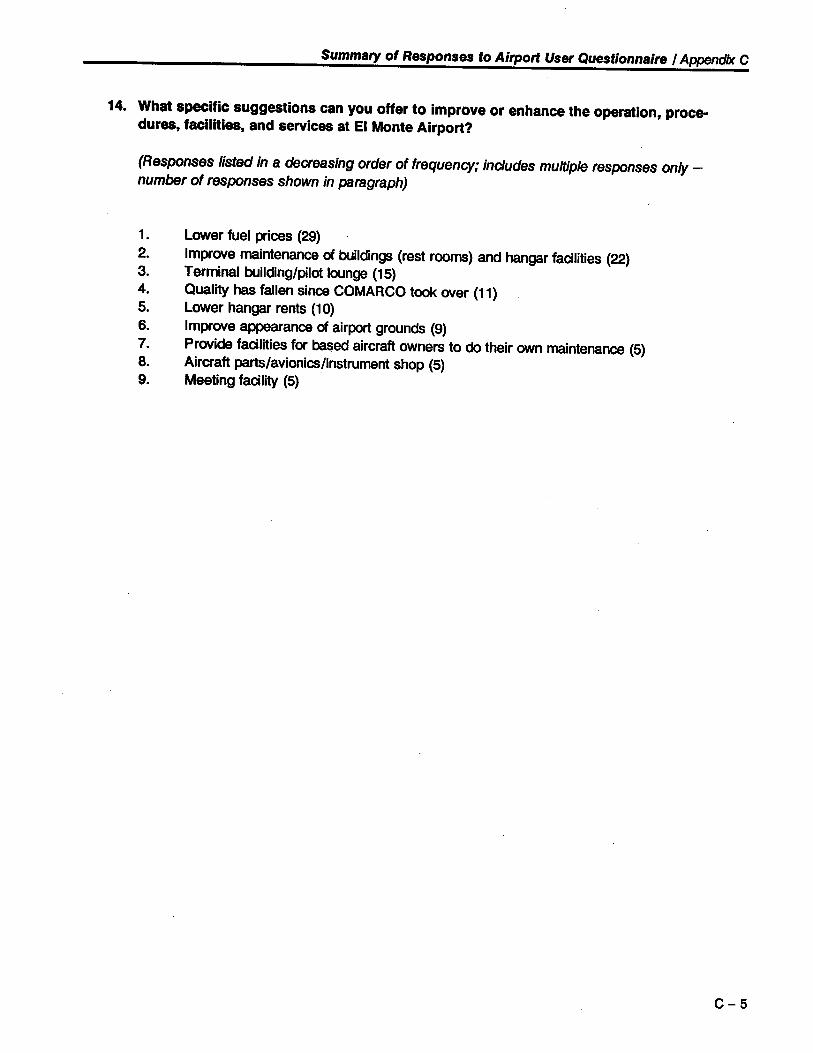
Summary of Responses to Airport User Questionnaire / Appendix C
14. What specific suggestions can you offer to improve or enhance the operation, proce-dures, facilties, and services at EI Monte Airport?
(Responses listed in a decreasing order of frequency; includes multiple responses only _number of responses shown in paragraph)
1. lower fuel prices (29)
2. Improve maintenance of buildings (rest rooms) and hangar facilities (22)3. Terminal building/pilot lounge (15)
4. Qualit ha fallen since COMARCO took over (11)
5. lower hangar rents (10)
6. Improve apparance of airport grounds (9)
7. Provide facilities for baed aircraft owners to do their own maintenance (5)
8. Aircraft part/avionics/instrument shop (5)
9. Meeting facility (5)
C-5

Appendix D
Airport Reference Codes of Selected Aircraft
AirportWingspan Approach Maximum
Aircraft Type Reference Spee Takeoff WeightCode (Feet)
(Knots) (Pounds)
Cessna 150 A-I/Small 32.7 55 1,600
Beechcraft V35B Bonanza A-I/Small 33.5 70 3,400
Piper PA-31-310 Navajo B-I/Small 40.7 100 6,200
Cessna 441 Conquest B-II/Small 49.3 100 9,925
Cessna Citation I B-I/Small 47.1 108 11 ,850
Swearingen Metro B-I/Small 46.2 112 12,500
Embraer 110 Bandeirante B-II 50.3 92 13,007
Cessna Citation II B-II 51.7 108 13,300
lear Jet 35A/36A D-I 39.5 143 18,300
Cessna Citation III B-II 53.5 114 22,000
Embraer 120 Brazila 8-11 64.9 0:121 23,353
HS 125-700A C-I 47.0 125 24,200
Shorts 360 B-II 74.8 104 26,453
Falcon 20 B-II 53.5 107 28,660
Gulfstream II D-II 68.8 141 65,300
Gulfstream ILL C-ii 77.8 136 68,700
Gulfstream iV D-11 77.8 145 71,780
Source: FAA Advisory Circular 150/5300-13/Appendix 13
D - 1

Appendix E
Navigational Facilty and Related Airport Data Requirements
NAVIGATIONAL FACILITY AN RELATED AIORT DATA REQUI11NTS
( DRAFT)
data. doc
. IF Procedure Data. The sponsor/òwner who requests an IF procedure shall provide the FAA with all of thebelow listed data needs including required coordinates, distaces, and elevations. Please note that ths data musbe CERTIFIED by a LICENSED surveyor. All NA YAI and airport positioiing coordinates must be determedin accordance with the Nort American Datu 1983 for the contiguous Uiited States and Alaskan areas. Thesponsor needs to provide four copies of a FAA approved airprt layout plan or scaled engineering dra''ing, PleasefiB in the appropriate data fields listed below that are not included in the ALP and leave blan those wllch are notapplicable to the procedure development request and retu the completed ronn to A WP-220.
A. Airport Information.
1. Type of approach requested (NB, YOR, ILS, MLS, GPS, etc.)
a. Approach St ra i ght- in Nonprec is i on GPS
b. Runway 1
2. Airport identier EMT
3. Offcial airport name El Monte Airport
4. City and stte El Monte. Cali forn i a
5. Local airport owner County of Los Angeles
6. Airport maager's telephone number, including area code
James Abing (818) 458-7389
7. Airport Reference Point (AR). Tlls is the offcial airport location and should be depicted on theairport layout plan. Advisory Circular 150/5300-13, Airprt Design, explais the correct method for determgthe AR. However, when oruy one ruway is involved, the exact halfway point and middle of the ruway shouldbe used as the AR. The fonnat for the AR should be in degrees, minutes, and seconds (to the nearest one-tenthof a second) latitudelongitude, with a horizonta geodetic accuacy of plus or minus 10 feet.
340509.598/ -1180205.427*
8. Airport elevation (llghest point of any airport usable landing suace) in mean sea level (MSL)
295.9'
9. Airport hours of operation; indicate in local time:
Monday-Friday 24 hrs.
Weekends-Holidays 24 hrs.
*Note: Lat/Lon data from El Monte Airport Obstruction Chart 5639 (surveyedMarch 1992) Hor. Oat. = NA083 and Vert. Oat. = NGV029.
E - 1

Navigational Facility and Related Airport Data Requirements / Appendix E
B. Runway Information. Provide the following information for all runways at the airport. Data is required forboth ends of the runway.
1. Runway (R06, R24, R19L, etc.): R01
2. Ruihvay threshold coordinat~s at the runway centerline on the approach side of the runway thesholdstripes, to the nearest one-hundredth of a second + horizontal geodetic accuracy.
340454.346/-1180214.141 (Disp. Thrnd.)340451.752/-1180215.623 (Appch. End of Pvmt.)
3 .~.a9 thtMoJi ~e¡R F~~ I.erel referenced elevation to the nearest one-tenth of a foot:
281.8' (Appch. End of Pvmt.)
Displaced theshold (if any) distance 290 ' Displaced theshold elevation 282.9 '
4. Runway stop end coordinates as in item subparagraph (2) above:
340527.443/-11801 55.230 (End of Pvmt.)
5. Runway stop end elevation as in subparagraph (3) above:
295.9'
6. Runway width and effective landing lengt in feet:
75' Wide x 3,995' Long (Pvmt. Length)*
7. Runway true bearng or geodetic azimuth in degrees, minutes and seconds or nearest I/ioo of a degree
2052529 (From North)
8. Runway profies, including elevation of ruway ends and displaced thesholds, high and low points,grade changes, and gradients. (see ALP set)
9. Highest elevation withn first 3,000 feet of each ruway landing surface (MSL) with vertcal accuacycomputed and submitted to the nearest one-tenth of a foot:
293.5'
10. Runway surface tye and condition: Asphalt - Good
1 1. Runway markings (non-precision, precision, or basic) and condition of the markings:
Basic - Good (Remarked in Late 1993)
12. Runway approach slope must be clear to 20:I/34:1 for at least the approach area criteria as contaedin AC 150/5300-13.
13. Runway Safety Area size 120' Wi de* must be clea in accordance with AC150/5300-13. Confrmed clear (Y / N) y*
14. Runway Obstacle Free Zone size 250 i Wi de* must be clea in accordacewith AC 150/5300-13. Confrmed clea (Y / N) N*
*Note: Declared Distances used to compensate for nonstandard RSA (see AirportMaster Plan and Airport Layout Plan set).
E - 2

Navigational Facility and Related Airport Data Recuirements / Apøendix E
B. Runwav Information. Provide the following information for all runways at the airport. Data is reqUired forboth ends of the runway.
1. Runway (R06, R24, RI9L, etc.): R19
2. Runway threshold coordinates at the runway centerline on the approach side of the runway thesholdstripes, to the nearest one-hundredth ofa second + horizonta geodetic accuracy.
340521.720/-1180158.500 (Disp. Thrhd.)340527.443/-1180155.230 (Appch. End of Pvmt.)
3. Runway theshold mean sea level referenced elevation to the nearest one-tenth of a foot:
293.7' (Disp. =rhrhd~)/295.9' (Appch. End of Pvmt.)
Displaced theshold (if any) distace 641 ' Displaced theshold elevation 293.7'
4. Runway stop end coordinates as in item subparagraph (2) above:
340451.752/-1180215.623 (End of Pvmt.)
5. Runway stop end elevation as in subparagraph (3) above:
281. 8 '
6. Runway width and effective landing lengt in feet:
75' Wide x 3,995' Long (Pvmt. Length)*
7. Runway tre bearng or geodetic azmuth in degrees, nnnutes and seconds or nearest 1/100 of a degree
252541 (From North)
8. Runway profies, including elevation of ruway ends and displaced thesholds, llgh and low points,grade changes, and gradients. (see ALP set)
9. Highest elevation withn first 3,000 feet of each ruway landing surface (MSL) with vertca accuacycomputed and subnntted to the nearest one-tenth of a foot:
293.7'
10. Runway suace tye and condition: Asphalt - Good
11. Runway markings ( non-precision, precision, or basic) and condition of the markings:
Basic - Good (Remarked in Late 1993)
12. Runway approach slope must be clear to 20:1/34:1 for at least the approach area criteria as contanedin AC 150/5300-13.
13. Runway Safety Area size 120' Wi de* must be clea in accordance with AC150/5300-13. Contnned clear (Y / N) y*
14. Runway Obstcle Free Zone size 250' Wi de* must be clea in accordacewith AC 150/5300-13. Contnned clea (Y IN) N*
*Note: Declared Distances used to compensate for nonstandard RSA (see AirportMaster Plan and Airport Layout Plan set).
E - 3

Navigational Facilty and Related Airport Data Requirements / Appendix E
C. Runwav Lighting. Infonnation about runways and Approach Lighting Systems is essential in order to pro\idevisibility reduction credits. Show lighting systems on airprt layout plans or engineering drawings.
1. Lights radio controlled (Y IN) No
List: MIRLS on durinQ hours of darkness
2. Frequency for radio activation: N/ A
3. Runway identifer: R/W 1-19
MIRL4. Runway light tye:
(Low Intensity Runway Lights (LIR), Medium Intensity Runway Lights (M), etc.)
Standard/on-Standard Standard
5. Runway approach light ty: (None, MASR. MAS, etc.) None
(Stadad/on-Stadad) N / A
Lengt of approach light system in feet N / A
6. V ASII API/pulsating light approach slope indicator (pLASI)
R/W 1 = AVASI-L (AnQle 4.95°) - R/W 19.= gVASI~R..(Aogle. 4.50°)
(Stadad/on-Stadad)
7. Touchdown Zone Lights (Y/N) No
(Stadad/on-Stadard) N/A
8. Lead-in Lights (Y IN) No
9. RVR (Y IN) No
10. Taxway Lights (Y IN) Yes
(Stadad/on-Standad) In-pvmt. cénterl ine
. 11. Runway Centerline Lights (Y/N) No
12. Displaced or relocted theshold marked and lighted (Y IN) Yes
13. REILS (Y/N) Yes-R/W ¡9
E - 4

Navigational Faciliy and Related Airport Data Recuirements / Appendix E
D. Airport Weather Infommation. Instrument Approach Procedures can be developed for locations without \veatherreportng and temminal forecasts; however, a local altimeter source must be available, otherwise some restrctionson the procedure may apply. Without weather reporting air tax and air carrer operators are not authorized toutilize the instrument procedures and the airport wil not be authorized as an alternate airport for any operator.National Weather Service (NS) report, other than from points witlln 2 nautical llles of the airport are notusable for instrment procedures.
1. Will Terllnal Weather Reportng be Available? (Y / N) Yes
If yes, the service wil be provided by:
a. Automated Flight Servce Station (AFSS) at :
b. National Weather Servce Offce (NWS) at:
c. Shared Weather Observation Program (SWOP) operated by :
d. Supplementar Aviation Weather Reportng Station (SA WRS) operated by:
e. Lillted Aviation Weather Reportng Stations (LA WRS) operated by:
f. Contract Weather provided by:
g. OtherfaciIty (specif): Currently being provi ded by EMT ATCT(1430Z-0500Z) and contract observer (0500Z-1430Z)
h. Automated SUUace Observation Station (ASOS)
Programed for installation (1995)
i. Automated Weather Observation Station (A WOS) (State category):
E - 5

Navigational Facility and Related Airport Data Requirements / Appendix E
j. Specify the days of the week and hours of the day the weather is taken:
SundayMondayTuesdayWednesdayThursdayFndaySaturday
24 hrs ./day7 days/week
2. When terminal weather reportng is not available, a local altimeter setting source should be provided inaccordance with Advisory Circular (AC) 91-14D (attached). Without a local altimeter source, a penalty may beapplied to the authonzed minimums or the procedure may not be authonzed.
a. Wil a local altimeter setting be instled and available to pilots on request?
If so, what frequency? . (Y IN) Frequency Yes (CTAF / ASOS)
b. Specif the days of the week and hours of the day the altimeter settng will be available.
SundayMondayTuesdayWednesdayThursdayFndaySaturday
24 hrs./day7 days/week
c. How will the altimeter setting be given to the pilot?
Unicorn (frequency)Company radio (frequency)Telephone (number) To be determinedAWOS/ASOS (frequency) To be determinedThrough Air Trafc CTAF
E. Air Trafc Control Data
L A public telephone or direct line must be available to an air trafc control (A TC) facility 24 hours aday in order to open and close IF flght plans. Telephone number To be determi ned
2. Wil Unicorn or an RCO be used to provide pilots with ATC cleaances or trafc information?(Normally no). If yes, specif the frequency and days of the week and hours of the day ATC informtion wi beavailable to the pilot. .
Frequency eTAF Day and hours A TeT 1430Z-0500Z
E - 6

Navigational Faciliy and Related Airøort Data Recuirements / ADoendix E
F. NA V AID Facilîtv Infonnation. if applicable.
1. Facility tye (ILS, MLS, NDB, etc.) N/A Re: GPS
2. Frequency
3. Equipment tye
4. Type of stand-by power
5. Number of transIIUers
6. Facility coordinates to the nearest one-hundredth of a second horizontal geodetic accuracy of +/- 10feet, vertical geodetic accuracy of +/- 1 foot. For multiple component systems such as ILS, MLS, etc., lîstcoordinates for each component.
7. Facilty elevation, MSL, accuate to the neaes one-tenth of a foot. Elevation values should be entered
on the airport layout plan at all NA V AI component sites.
8. Monitor category, circle one: (1, 3, 4).
9. Monitor location (FO, control tower, fire sttion, etc. )
10. Location of helicopter area if applicable:
G. Additional Infonnation for ILS, SDF, MLS, Localizer-Type Directional Aid (LDA), or LOC Approaches.
Note: All distaces should be accuate to the neaest one-tenth of a foot.
1. Localizer Data:
ILS Category: Cat I, Cat II, Cat II
True proposed or actual localizer course
LOC antenna distance from STOP END of ruway
LOC distace/direction from runway centerline
LOC offset
E - 7

Navigational Facility and Related Airport Data Requirements / Appendix E
LOC width at threshold
LOC course width
LOC back course, circle one
LOC antenna tye: (Traveling-Wave, etc.)
(Y I N)
LOC Lat
Dual Frequency
2. Marker Data
OM distace out centerline from runway theshold:
Long
(Y/N)
ft
ftOuter marker distace perpendicular from centerline
Note: If outer marker is a LOM, give name, if estblished
Lat Long
:M distace out centerline from runway theshold: _ ft
:M distance perpendicular from centerline ft.
:M Lat Long1M distace out centerline from runway theshold: _ ft
1M distnce perpendicuar from centerline
Lat
3. GS Data:
n.S category, circle one: Cat I, Cat II, Cat II
GS angle: (normly 3.00 degrees)
Long
GS distace perpendicuar to ruway centerline:
(a) Distace:
(b) Direction:
GS distace from ruway theshold: (centerline abeam)
GS theshold crossing height:
Runway elevation abea GS MSL:
E - 8

Navigational Facilty and Related Airport Data Reculrements I Appendix E
GS antenna height: AGL _ MSL_
GS tye (capture effect, etc.):
GS Lat Long
E - 9

Appendix F
Pavement Condition Analysis
EL MONTE AIRPORT
Introduction
The airfield pavements were evaluated as part of the Airport Master Plan study. This evaluationincluded a review of soils and pavement section information contained in the FAA PavementStrength Survey (Form 5335-1), review of the 1993 Pavement Evaluation prepared by Penfield &Smith, a visual pavement condition survey and calculation of the pavement condition index (PCI)ratings. Random or representative areas of each airfield pavement area were surveyed for visualpavement distress in accordance with guidelines in FAA Advisory Circular 150/5380-6. Randomsample units were used for larger pavement sections and representative sample areas for smallersections. Figure F-1 depicts the pavement areas and associated field survey sampling methodused.
The Micro PAVER pavement management computer program was used to calculate the PCIratings from the pavement distresses measured during the field survey. PCI values can range froma high of 100 (excellent) to a low of 0 (failed).
Pavement Conditions
The airfield pavements at EI Monte Airport are asphalt concrete, with PCI values ranging from alow of 66 (good) to a high of 100 (excellent). The distress observed is a result of aging andweathering of the surface and not aircraft loadings. The predominant types of distress observedinclude low- to medium-severity longitudinal and transverse cracks, low-severity weathering, andisolated low-severity patches. The PCI ratings for each pavement area are shown on Figure F-2.
The entire airport was treated with a slurry seal in January 1994. While not contributing directlyto the strength of the pavement, this surface treatment improves surface traction, prolongspavement life, and enhances the appearance of the Airport.
Maintenance/Repair Recommendations
Recommended pavement repair/maintenance projects for the Airport are summarized in Table F-1. The projects in this table are scheduled in 0- to 5-year, 5- to 10-year, and 10- to 20-year timeperiods according to their urgency in restoring the pavements and maintaining them in goodcondition.
The strategy of maintaining pavements in good condition is based on the relationship of pave-ment condition to rate of deterioration. As illustrated in Figure F-3, the rate of deteriorationincreases significantly as pavement condition drops. This increase becomes drastic when pave-ment conditions drop in the fair to poor range. Because of this drastic change, the additional costto rehabilitate a pavement in poor condition, versus good to fair condition, are significantly higher.
F - 1 .

Pavement Condition Analysis / Appendix F
Scheduling of the recommended pavement repair/maintenance projects was based upon minimiz-ing long-term repair costs. In this analysis¡ funding of the projects was not considered a limitingfactor. In cases where projects are considered to be equally important in terms of pavementmaintenance, user safety and operating costs were also considered in the ranking process.Without a substantial amount of historical performance data and an accurate picture of futureairpòrt conditions, it is diffcult to forecast beyond the 5- to 10-year period. Thus, the 10- to 20-year projects represent our best estimate of required maintenance projects for that period. Thepavements should be evaluated in 7 to 8 years to reassess maintenance needs.
Since the environment seems to be the primary cause of deterioration at the Airport, routinesealing will help delay further deterioration. The entire airport was sealed using an asphalt slurryseal in 1993, and was partially completed prior to our pavement evaluation. It is assumed thatmuch of the distress identified herein was corrected in this process. Thus, our recommendationsfor sealcoat in the 0- to 5-year timeframe would actually take place 3 to 5 years from the lastsealcoat. On runways, taxiways, and hangar areas, we recommend a latex modified .asphalt slurryseaL. On aprons, a coal tar slurry is recommended to protect the pavement from the harmfuleffects of fuel spillage.
F - 2
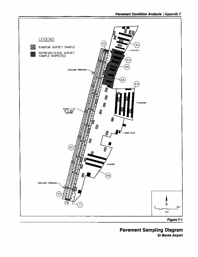
Pavement Condition Analysis / Appendix F
LEGEND
~a 600~Feet
figure f-1
~II
RANDOM SURVEY SAMPLE
REPRESENTATIVE SURVEYSAMPLE INSPECTED
T -HANGARS
RUNWAY 1-1975' X 3994'
(UGHlED)
DISPLACE 1HRESHOL \
Pavement Sampling DiagramEI Monte Airport

Pavement Condition Analysis / Appendix F
PCI RA TlNG
100
LEGEND
55
40
25
10
o
EXCELLENT
VERY GOOD
GOOD
FAIR
POOR
VERY POOR
FAILED
"
" " "
" "r -HANGARS
',' "
RUNWAY 1-19 ',' "75' X 3994' "
(UGHlE)"
DISPLACE THRESHOL \
o ~ 600~Feet
Figure F.2
pei RatingEI Monte Airport

Pavement Condition Analysis / Appendix F
Timeframe Project Pavement Project EstimatedNo. Area Description Cot
o - 5 Years No significant pavement repair/maintenance required.
Subtotal $ 835,00
5 - 10 Years 1 A1, A2, A3, A4, AS Slurry Seal 200,0002 R1, T1, T2, T3, T4 Overlay 720,000
Subtotal -0-
1 R 1, T1, T2, T3, T 4 Seal Coat 260,00010 - 20 Yeam 2 A6 Overlay 1,311,000
3 A1, A2, A3, A4, AS Reconstruction 771 ,000
Subtotal $2,342,000
TOTAL $3,262,00
Source: Hodges & Shutt (October 1994)
Table f-1
Recommended Airport Pavement Repair/Maintenance ProjectsEI Monte Airport

Pavement Condition Analysis I Appendix F
",-- .
, .~ -~.
000'- 75% Timera: 0-w 0:; ..0
:: Each $1.00..0 of0 0c: 0 :: -- renovation.Q '- a cost here...+-.-"Uc:0
Ü a: Pavement Will cost+- 4: deterioration $4 to $5l.c: versus time ifQ)
delayedE :: to hereQ) ..~ -0 0
~ ::0. a0 ~0. 0..Totala: .. Failure00
0.ra:w:;
0 5 10 15 20 25 30
Pavement Age
,.'
Reference: American Public Works Association'Paver Training Manual' (1986)
Figure F-3
Theoretical Pavement Deterioration CurveEI Monte Airport

Appendix G
Hangar Financing Options
EL MONTE AIRPORT
Hangars are unusual among airport facilities in terms of the ways in which they can be financed.Not all of the typical airport funding sources can be used for hangar development - hangars arenot eligible, for example, to receive federal AlP grants. Portions of the hangars' access taxiways,however, are eligible for AlP grants. Considering the high priorit assigned to construction ofadditional hangars at EI Monte Airport, it is appropriate to take a closer look at hangar financingoptions.
The attached table compares the advantages of five different public and private hangar financingoptions. While intended primarily for financing the development of permanent T-hangars, the fivefinancing options can also be applied to the development of portble hangars and corporate orexecutive style hangars.
At EI Monte Airport, the existing aircraft storage hangars have been developed by both theCounty and the private sector. Due to the increasing cost of development, it is anticipated thatthe majorit of all future hangar construction (fixed or portable types; ''T' or "box" types) wil be
financed and owned by the County. This financing approach is consistent with past Countypractice and permits the County to allocate its financial resources as appropriate to revenue-producing airport improvements.
With respect to EI Monte Airport, the Airport-owned/Airport-financed and Airport-owned/StateLoan Program-financed approaches to financing hangar development appear to offer the greatestlikelihood of success. It is anticipated that, at least for the near-term, any new hangars construct-ed at the Airport wil be financed in this manner.
G - 1

Hangar Financing Options / Chapter G
Privately Owned/Privately Financed
This approach is most often pursued at pubbicly owned airport that are unabbe to afford the initial development cost of hangarconstructon or prefer to use their limited financial resources for other higher priority project. The hangars are designed,financed, and owned by private sector interests. Title to improvement mayor may not revert to the airport upon expiration ofthe lease term.
Advantages
· No pubbic financing or capital required.· Private development can generally be accmplished at
lower cot and in less time than pubbic development.
· Pride of private ownership and ownership equity interestmay encourage above-average strctral maintenance
and facility utlization.· Airport gains immediate revenue from land area
rentl/use fees.
Airport Owned/Privately Financed
Disadvantages
· Airport either gains no equity interest in improvementsor gains no equity interest until term expiration.
· Revenue accing to airport is modest (i.e., generallyland rent only).
· Potential for private default and resultant turmoil.· Airport sacrfices a measure of contol to private
interests.· Potential for low quality or inconsistent design unless
airport owner sets precise design and constructonstandards.
With this approach, the airport owner obtains private sector financing to construct the hangars and subsequently owns andoperates them.
Advantages
· No pubbic financing or capital required.· Airport .owns. improvements thus faciltating control.
(Note that private financier may retain some element ofcontol over the facility and its use).
Airport Owned/Airport Financed
Disadvantages
· Private financing costs may be high.
· Loan assurances may encumber or constrain airport.· Private financial interests (banks, savings and loans in-
stiutons, developers, etc.) are generally not familar
with hangar development project.
This approach assumes that the airport has sufcient surplus income and/or retained earnings to self-finance hangarconstructon.
Advantages
· Generally results in the lowest 'financing. costs.· Airport owns improvement thus facilitating contol.· Use of airport funds does not impact community's
general funds or bonding capability.· Over the long term, airport realizes a significant
measure of revenue.
Disadvantages
· Only larger airport with adequate financial resources
are capabbe of pursuing this approach.· Utlizes frequenty scarce airport capital resources that
might better be applied toward other airportimprovement project for which alternative fundingsources are not availabbe. '
· Positve cash flow frequenty not realized by airport forseveral years.
Table G-1
Hangar Financing OptionsEI Monte Airport

Hangar Financing Options / Chapter G
Airport Owned/State Loan Program Financed
This method of hangar financing has been succssfully utlized by numerous airport owners in the state of California. Thepublic airport owner borrows the funds necessary for hangar development from the California State Airport Loan Program.The loan is then retired from hangar rental revenues over a period of up to 15 years.
Advantages Disadvantages
· Airport owns improvements thus facilitating contol.· Scarce airport and community funds are not required.· Interest rate charged (currently 5.9% per annum) is
attactvely below the rates availabbe from private
financing sources.· Loan can be retroactvely applied to eligibbe project.· Over the long term, airport realizes a signfcant measure
of revenue.
· The State Loan Program usually has backlog of loanrequests - sometimes as long as a year.
· Repayment schedule has constant principal paymentthus expenses usually exceed revenues in initial years.
Airport Owned/Publicly Financed
Using this arrangement, the airport utlizes funds or financial resources (general fund, general obligation bonds, revenuebonds, etc.) to construct hangars.
Advantages Disadvantages
· Airport owns improvements thus facilitating contol.. Scarce airport funds are not required.
· Public resources may be unavailabbe or required forhigher priorit community project.
· Bonding procss may require security pledge and/orvote of cizenry.
Source: Hodges & Shut (November 1994)
Table G-1 continued
Appendix H
Airport-Oriented Restaurants/Coffee Shops
Obserations Regarding the Opeationof
Restaurants and Coffee Shopson
General Aviation Airports
There is a pervasive feeling throughou th general aviation communit tht every airport of any moestsize needs and is capabl of supprting an on-airport restaurant. On th sUnace, an on-airprtrestaurant appars to be a reasonable propoition. It offers th "excing allure" of aviation actvit andhas ready accs to a somewhat captve customer bae - th baed and transient pilot and pa_sengrs tht frequent the airport.
However, th recrd of succs for mot general aviation airport restaurant has not been goo. Thereare seemingly more failures thn succsses in this buiness. One needs only to visit a few lol
airport to learn of th numerous attempt to eiter start or sustain a viable on-airprt restaurant _mot end in failure.
Restaurants locted on general aviation airp are typically on of two kinds - th small "Mom &
Pop" style coffee shop/snackbar or th uppr-scale, full-service public-accss eatery featuring anaeronutcal thme.
The .coffee shop/snackbar" typically caters to pilot and tenant baed at th airport. In additon,
transient pilot and pasengers may fly into the airprt and purchase foo and drink - eiter as a
prmary detination or just pasing through. There isn't much public street trffc or locl communitclientle. The baic on-airprt coffee shop customer is somewhat informally attred (after all, he justdrained 7 quart of dirt oil from his lycoing 0-320 engine), bus one cup of coffee (coplains aboutth cot), and sit around mot of th day talking about airplanes and complaining about the FAA. The
small on-airprt coffee shop is th locl pilot and aviation enthusiast hang-out - dusty old moel
planes hang frm th ceilng and yellowing aeronautcal sectonals and doeared airpane photos lineth walls. The place is buy on goweather summer weekends at lunc time, but is slow most othertimes. There is not much volume and very lite profit - if any.
Of course, thre are succsful on-airprt coffee shops (airpo like Petaluma, Auburn, Chino, Brackett
Field, Big Bear, and Lampson Field in California come to mind). These restaurant are well-known
throughou thir respectve pilot communites as goo places to fly to on a nice summer weekend for
th proverbial $75 airport hamburger. They are moestly sized and informally operated to minimizecots and remain attactve to their pilot/airport user customer base.
H - 1

Airport-Oriented Restaurants/Coffee Shops / Appendix H
The secod kind of on-airport restaurant is th full-service, public-accss eatery. This restaurant
typically endavors to attact th uppr-scale lunc and dinner crowd by featuring qualit foo and drinkwit th allure and exciment of an aeronautcal settng. This type of restaurant relies heavily upon thlocl polation bae, area buinesses and roadside trffc for it clientele. A very small percentge
(less thn 10%) of it buiness comes from pilot, passengers, and airprt tenant. Based pilot andairprt tenant typically do't patronize such establishments beuse thse restaurant tend to berelatively expensive and not conducie to informal "hanging around." Frequenty, thse restaurant
have a minimum table service charge, no counter service, and actely discorage "informal. cus-tomrs.
Through advertsing and word of mout, such restaurant can attact th transient pilot and pasengersfor a meal. Flying to Acm Communit Airpo for a nice lunc or dinner was on a poular form ofentertinment for many general aviation pilot. Wit th recent deine in general aviation actvit,
partcularly receationl and discretionary flying, this customer bae has eroded signifcantly.
To survive, th full-servic on-airport restaurant must have a strong, non-airpo-related customer baeand ofer qualit foo and service. The aeronautcal thme wil draw customers th first time bu goofoo and service is required to keep thm coming back.
The aeronautcal thme tht distinguishes such restaurant is, unfortunately, diminishing in it impact
Many customers co to on-airprt restaurant to see the planes, light, and actit associated with anacte, vibrant airport. In these days of declining general aviation actvit, however, thre are preciousfew planes flying. large acreage mult-runway airport frequently place th flight actvit a considerabledistance from th restaurant windos - closeup viewing is dificult at best. Electrical energy conser-
vation programs mean tht few runway and taiway light are visible at night. FAA securit restrictons,
partcularly at air carrier and commuter airport, inhibi accs to th ainield and project an inhopitbleforess mentalit. At some airport, general aviation fly-in customers cannot tai directly to th res-.
taurant due to airprt securit requirements - the pilot and pasengers are required to take a fre-
quently incovenient courtesy car or taicab to th restaurant via public roads.
Succssful examples of full-service public-accss restaurant includ th 94th Aero Squadron and306 Bomb Group thme restaurant at San Jose International Airpo (CA) and Sarasot-BradentonAirpo (FLA), respectely, and the Blue Max Restaurant at Boeing Field in Seattle NNA).
Generally speking, it is no practcal to sucssfully mix th two restaurant types at one loction. Thetwo resurant types serve substantially diferent clienteles wit differing service and facilit
requirements.
The following additonal thughts and observations regarding on-airport restaurants are offered:
· Airpo/Pilot Guides are a useful tool in advertsing both on-airport and near-airport restaurant.
There are even speal guides that describe nothing but on-airport restaurant.
H - 2

Airøort-Oriented Restaurants/Coffee Shoøs / ApTJndix H
· Busines/coate aircraft foo catering ofers some poental for addd restaurant revenue _
partlarly at buier general aviation airprt in metropoitn areas. However, onairprt res-
taurants could face sti catering competion from of-airpo restaurant and locl delicatessens.
· A number of restaurant are locted on airprt with contguos corprate/ industral parks.Usually, thse restaurant consider th nearby corporate/industrl parks as an importnt element
of thir customer bae - partcularly at lunc time.
· Ocionally, a locl commnit restaurant operator wil establish a .sateiiite. restaurant operationat th lol airprt. Hopefully. such an operator wil know th locl market and wil be able to
reduce cots through bulk purchasing and shared administration.
· Infrasucre and equipmnt co for on-airport restaurant are relatiely high. This is partcularlytrue for strt-up operations. This generally requires high initl capilization and a relatiely long
lease term. Neiter th airprt operator nor th restaurateur is typically interested in thse terms
for such a spelatie buiness endavor.
Prepared in August 1993 by David B. Heal, Hodes & Shut, Santa Rosa, California.
H - 3

Appendix I
Noise Model Calculation Data
EI Monte Airport
Totl Operation Touch & Go's
Annual Average Day Percentage " ofAircraft Typ OperationSinge-Engine, PropUer, Fixed Pit 90,00 246.6 48.3 50.0Single-Engine, PropUer, Variable Pit 66,302 181.7 35.6 10.0TwiEngine, Propner, Pis 9,000 24.7 4.8 5.0Twin-Engine, Turbop 800 2.2 0.4 0.0Small Busines Jet (e.g., Citti I) 200 0.6 0.1 0.0Helicrs 20,00 54.8 10.8 50.0Totl 186,302 510.4 100.0 35.5
Totl Operation Tou & Go's
Annual Average Day Percentage " ofAircraft Typ OperationSingle-Engine, Propller, Fixed Pit 90,00 246.6 42.9 40.0Single-Engine, Propner, Variable Pit 73,00 200.0 34.8 10.0Twin-Engine, Propner, Pistn 11 ,200 30.7 5.3 5.0TwiEngine, Turborop 2,000 5.5 1.0 0.0Small Business Jet (e,g., Citti I) 800 2.2 0.4 0.0Helicrs 33,00 90.4 15.7 40.0Totl 210,000 575.3 100.0 27.2
I - 1

Noise Model Ca/cu/aUon Data / Appendix I
Percentage of Operationby Aircraft Typ
Day Evening Night7:00 a.m. 7:00 p.m. 10:00 p.m.
Aircaft Typ 7:00 p.m. 10:0 p.m. 7:00 a.m.
Single-Engine, Fixed Prop Ldg & T/O 94.0 5.0 1.0Touch&Go 95.0 5.0 0.0
Single-Engine, Variable Prop Ldg & T/O 93.0 6.0 1.0Touch&Go 96.0 4.0 0.0
Twi-Engine, Pisn Prop Ldg & T/O 92.0 7.0 1.0Touch&Go 97.0 3.0 0.0
Twin-Engine, Turbop Ldg & T/O 92.0 7.0 1.0
Small Business Jet Ldg & T/O 92.0 7.0 1.0Helicrs Ldg & T/O 85.0 10.0 5.0
Touch&Go 96.0 4.0 0.0
Percentage ofLandings &
T ouch-and-Go
Percentage ofTakeof
Aircaft Typ
All Aircaft Day,Evening,
Night
Rwy 1
10.010.010.0
Rwy 19
90.090.090.0
Rwy1
10.010.010.0
Rwy 19
90.090.090.0
Runway 1 Runway 19
Staight Left Right Straigh Left RightAircraft Typ In Dowwind Dowwind In Dowwind Dowind
Single-Engine 1.0 4.0 4.0 21.0 50.0 20.0Twin-Engine & Jet 1.0 4.0 4.0 21.0 50.0 20.0Helicrs 1.0 4.0 4.0 21.0 50.0 20.0
1-2

Noise Model Calculation Data / Appendix i
Runway 1 Runway 19
Straight 45° 45° Straight 45° 45. Right LeftAircraft Typ In Left Right Out Left Right Downwind Dowind
Single-Engine 1.0 2.0 3.0 10.0 6.0 6.0 23.0 45.0Twin-Engine & Jet 1.0 2.0 3.0 10.0 6.0 6.0 23.0 45.0Helicrs 1.0 2.0 3.0 10.0 6.0 6.0 23.0 45.0
Runway 1 Runway 19
Aircaft Typ Right Pattrn Left Pattrn Right Pattrn Left Pattrn
Airpnes 2.0 2.0 90.0 6.0Helicrs 2.0 2.0 90.0 6.0
Sourc: Hodges & Shut (July 1994)
1- 3

Appendix J
Initial Study of Environmental Impacts
INITIAL STUDYEMnRONMNTAL CHECKLIST FORM
I. BACKGROUND
3.4.5.
Report
i.2.
Name of Proponent: County of Los AngelesAddress and Phone Number of Proponent:
Department of Public WorksAviation Division900 South Fremont Avenue, 2nd FloorAlhambra, California 91803-1331818-48-7389
Date of Checklist Submission:Agency Requing Checklist: County of Los AngelesName of Proposal, if applicable: EI Monte Airport Master Plan
II. EMnRONMNTAL IMPACTS
(Explanations of all"yes" and "maybe" as well as pertinent "no" answers arerequired on attached sheets.)
YES MAYBE NO
L Earth. Will the proposal result in:
a. Unstable earh conditions or in changes in geologicstructures? x
b. Disruption, displacement, compaction or over-
covering of the soil? xc. Change in topography or ground surace relief
features? xd. The destruction, covering or modification of any
unique geologic or physical features? xe. Any increase in wind or water erosion of soils,
either on or off the site? x
J - 1

Initial Study of Environmental Impacts / Appendix J
YES MAYBE NOf. Changes in deposition or erosion of beach sands,
or changes in siltation, deposition or erosion whichmay modiy the channel of a river or stream or thebed of the ocean or any bay, inlet, or lake?
Å
g. Exposure of people or property to geologic hazardssuch as earhquakes, landslides, mudslides,
Å
ground failure, or simlar hazards?
2. Air. Will the proposal result in:
a. Substantial air emissions or deterioration of am-bient air quality over the long term?
Å
b. The creation of objectionable odors or dust?Å
c. Alteration of air movement, moisture or tempera-ture, or any change in climate, either locally orregionally? X
3. Water. Will the proposal result in:
a. Changes in currents, or the coure or diection ofwater movements, in either marne or freshwaters?
Å
b. Changes in absorption rates, drainage patterns orthe rate and amount of surace water runoff?
Å
c. Alterations to the course or flow of flood waters?Å
d. Change in the amount of surace water in anywater body? (e.g., perennal or intermittentstreams; seasonal or year-round springs; pondsand marshes)
Å
e. Alteration of water quality, including but not limi-ted to temperature, dissolved oxygen or turbidity?
Å
f. Alteration of the diection or rate of flow ofgroundwaters, including changes in infltration orpercolation rates?
Å
J - 2

Initial Study of Environmental Impacts / Appendix J
YES MAYBE NO
g. Change in the quantity of groundwaters, eitherthrough diect additions or withdrawals, or Xthrough interception of any aquier by cuts orexcavations?
h. Substantial reduction in the amount of waterotherwse available for public water supplies? X
4. Plant Life. Will the proposal result in:
a. Change in the diversity of species, or number ofany species of plants (including trees, shrbs,grass, crops, and aquatic plants)? X
b. Reduction of the numbers of any unique, rare, orendangered species of plants? X
c. Introduction of new species of plants into an area,or in a barer to the normal replenishment of
existing species? Xd. Reduction in acreage of any agrcultural crop? Xe. Any effect upon a Signficant Ecological Area
which is identified in the Los Angeles CountyGeneral Plan? X
5. Animal Life. Will the proposal result in:
a. Change in the diversity of species, or numbers ofany species of animals (birds, land animals in-cluding reptiles, fish and shellfish, benthic organ-isms or insects)? X
b. Reduction of the numbers of any unique, rare orendangered species of animals? X
c. Introduction of new species of animals into anarea, or result in a barer to the migration ormovement of animals? X
d. Deterioration to existing fish or wildlife habitat? X
J - 3

Initial Study of Environmental Impacts / Appendix J
YES MAYBE NO
6. Noise. Win the proposal result in: .xa. Increases in existing noise or vibration levels?
b. Exposure of people to severe noise levels? .x7. Light and Glare. Win the proposal produce new light
or glare? .x8. Land Use. Win the proposal result in:
a. A substantial alteration of the present or plannedland use of an area? .x
b. A confct with adopted envionmenta plans andgoals of the community where it is located? .x
9. Natural Resources. Win the proposal result in:
a. Increase in the rate of use of any natural resour-ces? .x
b. Substantial depletion of any nonrenewable naturalresource? .x
10. Risk of Upset. Win the proposal involve:
a. A risk of an explosion or the release of hazardoussubstances (including, but not limited to oil, pes-ticides, chemicals, or radiation) in the event of anaccident or upset conditions? .x
b. Possible interference with an emergency responseplan or an emergency evacuation plan? .x
c. Exposure of people or property to a flooding haz-ard, such as a change in location or flooding in theevent of an accident or upset condition? .x
1L Population. Win the proposal alter the location, dis-tribution, density, or growth rate of the human popula-tion of an area? .x
J - 4

Initial Study of Environmental Impacts / Appendix J
YES MAYBE NO
12. Housing. Win the proposal afect existing housing, orcreate a demand for additional housing?
Å
13. TransportatioiýCirculation. Win the proposal result
in:
a. Generation of substantial additional vehicularmovement?
Å
b. Effects on existing parking facilities, or demandfor new parking?
Å
c. Substantial impact upon existing transportationsystems?
Å
d. Alterations to present patterns of circulation ormovement of people and/or goods?
Å
e. Alterations to waterborne, rail or air traffic?Å
f. Increase in traffic hazards to motor vehicles, bicy-clists, or pedestrans?
Å
14. Public Services. Win the proposal have an effectupon, or result in a need for, new or altered governen-tal servces?
Å
15. Energy. Win the proposal result in:
a. Use of substantial amounts of fuel or energy?Å
b. A substantial increase in demand upon existingsources of energy, or require the development ofnew sources of energy?
Å
16. Utilities. Win the proposal result in a need for new
systems, or substantial alterations to utilities such as,but not limited to, gas, water, sewer, storm waterdrainage, or solid waste disposal?
Å
J - 5

Initial Study of Environmental Impacts / Appendix J
17. Human Health. Will the proposal result in:
a. Creation of any health hazard or potential health
hazard (excluding mental health)?
b. Exposure of people to potential health hazards?
18. Aesthetics. Will the proposal result in:
a. Obstruction of any scenic vista or view from exis-
ting residential areas, public lands, or roads?
b. Creation of an aesthetically offensive site?
c. Change in character of the general project area?
19. Recreation. Will the proposal result in an impactupon the quality or quantity of existing recreationalopportunities?
20. Cultural, Archaeological, Historical, and Paleon-
tological Resources. Will the proposal result in:
a. Alteration of or the destrction of a prehistoric or
historic archeological site?
b. Alteration or destrction of a paleontological re-
source?
c. Adverse physical or aesthetic effects to a prehis-toric or historic building, structure, or object?
d. Physical changes which would affect unique ethnic
cultural values?
e. Restriction of existing religious or sacred uses
within the potential impact area?
J - 6
YES MAYBE NO
Å
Å
Å
Å
Å
Å
Å
Å
Å
Å
Å

Initial Study of Environmental Impacts / Appendix J
2L Mandatory Findings of Significance.
a. Does the project have the potential to degrade the
quality of the envionment, substantially reducethe habitat of a fish or wildlife species, cause a
fish or wildlife population to drop below self-sus-taining levels, threaten to elimnate a plant oranial community, reduce the number or restrict
the range of a rare or endangered plant or anialor eliminate importnt examples of the major peri-ods of Californa history or prehistory? .
b. Does the project have the potential to achieve
short-term, to the disadvantage of the long-term,
envionmental goals? (A short-term impact on theenvionment is one which occurs in a relativelybrief, definitive period of time while long-termimpacts will endure well into the future.)
c. Does the project have impacts which are individu-
ally limited, but cumulatively considerable? (Aproject may impact on two or more separate re-sources where the impact on each resource is rela-tively small, but where the effect of the total ofthose impacts on the envionment is signficant.)
d. Does the project have envionmental effects which
will cause substantial adverse effects on humanbeings, either diectly or indirectly?
YES MAYBE NO
Å
Å
x
Å
J - 7

Initial Study of Environmental Impacts / Appendix J
III. DISCUSSION OF ENVRONMNTAL EVALUATION
General Note: The EI Monte Aiort Master Plan is a comprehensive assess-ment of the facility and servce enhancements requied to see the Aiort fulfll itspublic servce role through the year 2013. This Master Plan builds upon theAiort Layout Plan approved by the County of Los Angeles in 1986.
The following key findings and recommendations are identified,in the MasterPlan:
· The Aiort's future operationaVservce role is not expected to dier signfi-
cantly from. the role the Aiort has served since its fist use in 1936.
· There are no proposed changes to the basic confguration of the runway/taxi-way system.
· Within the initial 5-year period, the following key Aiort improvements arerecommended by the Master Plan:
Construct public-use termnal building (4,000 square feet)
Construct additional aicraf storage hangars (30 spaces)
Install Automated Surace Observation System (ASOS)
Install Runway End Identification Lights (HElL) to Runway 1
Renovate aviation fuel storage and dispensing facilities
Develop supplemental aviation support area (5 acres)
· Towards the latter par of the 20-year master planning period, it is anticipa-ted that the following Aiort improvements may be requied:
Construct additional aicraf storage hangars (20 spaces)
Replace aield lighting system
Acquire additional property to support Aiort development (8 acres)
Rehabilitate airfeld pavement
The sum of the airfeld development proposed in the Master Plan represents amitigable impact on the envionment. The appropriate mitigation actions areidentified herein and in the Master Plan.
J - 8

Initial Study of Environmental Impacts / Appendix J
The following is submittd in response to the preceding envionmenta impactchecklist:
1 b It is proposed that a &,4-acre area of level land located in the midst offully-developed Fixed Base Operations (FBO) facilities be developed as apaved aircraf parking apron or site for additional FBO facilities. Thesubject area is currently neither irgated nor developed, and is sparsely
covered with native grasses. Pavement of this area would result in theovercovering of the site's soiL. Use of this area for the above noted pur-poses is consistent with surounding land uses.
1 e New development will result in creation of additional impervous sur-faces (i.e., pavement and strctures) and, therefore, additional stormwater run -off. The engineering design of the new facilities should in-clude provisions for handling run-off to prevent an increase in erosion.
2 a The forecasted increases in aircraf operations (approximately 0.6% per
annum) will increase the amount of emissions attrbutable to the Aiort
(both diectly by aicraf and indiectly by automobiles associated with
aiort users). However, the total amount of emissions will not have asignficant effect on regional ai quality. The amount of emissions isnegligible compared to the much larger effect attrbutable to the existingand planned urbanized development in the area.
2 b Aicraft engines, especially turbine engines, produce exhaust odors which
some people find objectionable. However, the volume of use by turbineaicraf, which are typically the most objectionable, is forecast to beinsigncant and no signficant change will occur with the other enginetypes. New state and federal ai quality standards are expected to ad-dress the limited emissions and odors associated with the fueling andoperation of aicraf. Site watering and other techniques should be used
durng constrction to minimize dust and wind erosion.
3 b AB described in Ie, the planned addition of pavement and structures will
slightly increase the amount of storm runoff. This will result in a minorincrease in flows of water into the existing storm water drainage system.The drainage from the Aiort outlets diectly into the Rio Hondo Chan-
neL. Any increase in runoff due to the additional impervious surace (i.e.,pavement and structures) would be minial and thus insignficant. Rio
Hondo Channel has adequate capacity to handle this increase in runoff.
3 e In a manner similar to roads, the run -off from aield pavement can be
expected to contain materials associated with the vehicles which use it(aicraft, automobiles, and trucks). The amount of these materials issmall and no specific mitigation measure is proposed. Accidental spillageassociated with aircraf fueling operations has a greater potential toaffect surace water quality. Curent state and federal hazardous mate-
rials regulations (which require increasingly strngent controls over the
J - 9

Initial Study of Environmental Impacts / Appendix J
6a
7
8 a
9 a
10 a
12
13 a
J - 10
next decade) are adequate to protect the envionment. There are nounusual conditions at EI Monte Aiort which require special mitigationmeasures.
Forecasted increases in aicraf operations (approximately 0.6% per
annum) will not signficantly increase the cumulative level of noise ex-perienced off of airport property, and single-event noise levels are notanticipated to change signficantly. Continued use of the Aiort's ai-
craf noise abatement procedures should prove effective in minizingand mitigating aicraf noise impacting off-Aiort land uses.
The principal change in lighting identifed in the Aiort Master Planwill be the addition of Runway End Identifier Lights (REIL), which willbe added at the threshold of Runway 1. A special study is suggested todetermne an appropriate way of mitigating REIL flash annoyance thatcould potentially impact off-airort land uses.
An 8-acre site that is contiguous to the northeast boundar of the Aiortis proposed for future acquisition in support of the Aiort. Ths site is
curently in use as an elementa school with associated strctures andpaved and grass playground areas. Should this site be developed insupport of the Aiort, it is likely these uses will be changed.
Anual aicraf operations are forecasted to increase by 0.6%. It can beassumed, therefore, that if the same types of aicraf continue to use the
. Aiort, the rate of use of petrochemicals (i.e., aviation fuel and oil)
associated with EI Monte Aiort will increase at the same rate.
Inherent in the operation of an aiort is the potential for an explosion orrelease of hazardous materials (i.e., fuel) in the event of an accident.There are, however, no existing or planned operations at EI Monte Ai-port that present an unusual level of risk. Curent land use measuresare in place to mitigate this risk. Additional measures are provided forin this Master Plan.
The future development of the supplemental aviation support areas tothe northeast and south of the Aiort has the potential to affect ad-jacent residential land uses. Pror to development of these areas, acompatibility plan should be formulated which minimizes the impact ofdevelopment on adj acent residential land uses.
Associated with the forecasted increase in aicraf operations is a minor
increase to the amount of ground vehicular movement. The increasedamount of traffic is minor compared to the larger volume attrbutable tothe existing business and residential development in the Aiort en-vions.

Initial Study of Environmental Impacts I Appendix J
13 b The additional parking requied to serve the projected increase in vehicu-lar traffic will be accommodated by on-airort parking areas designatedin the Aiort Master Plan.
13 d Depending on the nature of on-Aiort development, ground and pedes-
trian circulation near the sites may be slightly altered.
13 e Ai trafc is forecast to increase from its curent level of 186,302 annual
operations to an estimated 210,000 annual operations in 2013. The Planis designed to accommodate this projected demand for aviation servcesat the EI Monte Aiort.
14 Additional public servces would be required to protect and maintain anyexpanded facilities proposed by the Master Plan. However, the effectwould be minor. Revenues generated by increased airport usage wouldbe expected to (at least parially) offset the added costs.
16 Depending on the nature of development, additional utility servces maybe requied to support these potential new facilities. However, no newsystems or substantial alterations to existing utilities will be required.
18 a The site to the south is curently undeveloped vacant land. The site tothe northeast is currently an elementa school and playground. Shouldthese sites be developed in support of the Aiort, new strctures mayobstruct the view from existing residential areas, public lands or roads.As noted in Comment 12, a compatibility plan should be developed tominimize this impact.
18 c Development of the two sites fròm their curent uses (vacant land andelementary school) to uses which support the Aiort could have animpact on the character of the adjacent residential areas. Any changesin land use would be done afr consultation with local City Officials andinput from a community meeting.
19 To many of the aicraf owners based at EI Monte Aiort, flying isprincipally a recreational activity. The projects identifed in the MasterPlan will support this recreational activity. No other effects on recrea-
tion on- or off-airort are anticipated.
J - 11

Initial Study of Environmental Impacts I Appendix J
On the basis of this initial evaluation:
I find the proposed project COULD NOT have a signficant effect on theenvionment, and a NEGATIVE DECLATION will be prepared.
I find that although the proposed project could have a signficant effect on theenvionment, there will not be a signficant effect in this case because themitigation measures described on an attached sheet have been added to theproject. A NEGATIV DECLATION WILL BE PREPARED.
I find the proposed project MAY have a signficant effect on the envionment,and an ENVIRONMNTAL IMPACT REPORT is required.
Date(Name)
For Countv of Los Aniæeles
J - 12

Appendix K
Glossary
ABOVE GROUND LEVEL (AGL): An elevation datum given in feet above ground leveL.
AIR CARRIER: A person who undertakes directly by lease, or other arrangement, to engage in airtransporttion. (FAR 1) (Also see Certificated Route Air Carrier)
AIR CARRIERS: The commercial system of air transportation, consisting of the certificated routeair carriers, air tais (including commuters), supplemental air carriers, commercial operators oflarge aircraft, and air travel clubs. (FAA Census)
AIR ROUTE TRFFIC CONTROL CENTER CARTeC): A facilit established to provide air traffccontrol service to aircraft operating on IFR flght plans within controlled airspace, principallyduring the en route phase of flght. When equipment capabilities and controller workload permit,certain advisory/assistance services may be provided to VFR aircraft. (AIM)
AIR TAXI: A classifcation of air carriers which directly engage in the air transportation of persons,propert, mail, or in any combination of such transportation and which do not directly or in-directly utilize large aircraft (over 30 seats or a maximum payload capacit of more than 7,500pounds) and do not hold a Certificate of Public Convenience and Necessit or economic author-
it issued by the Department of Transportation. (Also see commuter air carrier and demand air
taxi.) (FAA Census)
AIR TRFFIC CONTROL (ATC): A service operated by appropriate authority to promote thesafe, orderly, and expeditious flow of air traffic. (FAR 1)
AIRCRAFT ACCIDENT: An occurrence associated with the operation of an aircraft which takesplace between the time any person boards the aircraft with the intention of flght and all such .persons have disembarked, and in which any person suffers death or serious injury, or in whichthe aircraft receives substantial damage. (NTSB)
AIRCRAFT APPROACH CATEGORY: A grouping of aircraft (Categories A-E) based on 1.3 timestheir stall speed in their landing configuration at their maximum certificated landing weight.(Airport Design)
AIRCRAFT OPERAll0N: The airborne movement of aircraft in controlled or non-controlledairport terminal areas and about given en route fixes or at other points where counts can bemade. There are two types of operations - local and itinerant. (FAA Stats)
AIRCRAFT PARKING LINE LIMIT (APL): A line established by the airport authorities beyondwhich no part of a parked aircraft should protrude. (Airport Design)
K- 1
Glossary I Appendix K
AIR/FIRE A lTACK BASE: An established on-airport base of operations for the purposes of aerialsuppression of large-scale fires by specially-modified aircraft. Typically, such aircraft are operatedby the California Department of Forestry and/or the U.S. Forest Service.
AIRPLANE DESIGN GROUP (ADG): A grouping of airplanes (Groups I - V) based on wingspan.
(Airport Design)
AIRPORT: An area of land or water that is used or intended to be used for the landing andtakeoff of aircraft, and includes it buildings and facilities, if any. (FAR 1)
AIRPORT ELEVATION: The highest point of an airport's usable runways, measured in feet abovemean sea leveL. (AIM)
AIRPORT HAZARD: Any structure or natural object located on or in the vicinit of a publicairport, or any use of land near such airport, that obstructs the airspace required for the flight ofaircraft in landing or taking off at the airport or is otherwise hazardous to aircraft landing, takingoff, or taxiing at the airport. (Airport Design)
AIRPORT LAYOUT PLAN: A scale drawing of existing and proposed airport facilities, theirlocation on the airport, and the pertinent clearance and dimensional information required todemonstrate conformance with applicable standards.
AIRPORT REFERENCE CODE (ARC): A coding system used to relate airport design criteria to theoperational and physical characteristic of the airplanes intended to operate at the airport.(Airport Design)
AIRPORT REFERENCE POINT: A point established on an airport, having equal relationship to allexisting and proposed landing and takeoff areas, and used to geographically locate the airport andfor other planning purposes. (Airport Design)
AIRPORT TRFFIC CONTROL TOWER (ATCl: A terminal facilit that uses air/ground com-munications, visual signaling, and other devices to provide A TC services to aircraft operating inthe vicinit of an airport or on the movement area. (AIM)
AIRWAY/FEDERAL AIRWAY: A Class E airspace area established in the form of a corridor, thecenterline of which is defined by radio navigational aids. (AIM)
ALERT AREA: A special use airspace which may contain a high volume of pilot training activitiesor an unusual type of aerial activity, neither of which is hazardous to aircraft. (AIM)
APPROACH LIGHT SYSTEM (ALS): An airport lighting system which provides visual guidance tolanding aircraft by radiating light beams in a directional pattern by which the pilot aligns theaircraft with the extended runway centerline during a final approach to landing. Among thespecific types of systems are:
K-2

Glossary I Appendix K
· LDIN - Lead-in Light System.
· MALSR - Medium-intensit Approach Light System with Runway Alignment Indicator Lights.· ODALS - Omnidirectional Approach Light System, a combination of LDIN and REILS.· SSALR - Simplified Short Approach Light System with Runway Alignment Indicator Lights.
(AIM)
APPROACH SPEED: Th recommended speed contained in aircraft manuals used by pilots whenmaking an approach to landing. This speed wil vary for different segments of an approach aswell as for aircraft weight and configuration. (AIM)
AUTOMATED WEATHER OBSERVING SYSTEM (AWOS): Airport electronic equipment whichautomatically measures meteorological parameters, reduces and analyzes the data via computer,and broadcasts weather information which can be received on aircraft radios in some applica-tions, via telephone.
AUTOMATIC DIRECTON FINDER (ADF): An aircraft radio navigation system which senses andindicates the direction to a L/MF nondirectional radio beacon (NDB) ground transmitter. (AIM)
AUTOMATIC TERMINAL INFORMATION SERVICE (A TIS): The continuous broadcast of record-ed non-control information in selected terminal areas. (AIM)
BACK COURSE APPROACH: A non-precision instrument approach utilizing the rearward projec-tion of the ILS localizer beam.
BASED AIRCRAFT: Aircraft stationed at an airport on a long-term basis.
BUILDING RESTRICTON LINE (BRL): A line. which identifies suitable building area locations onairport.
CEILING: Height above the earth's surface to the lowest layer of clouds or obscuring pheno-mena that is reported as "broken", "overcast", or "obscuration" and is not classifed as "thin" or"partial". (AIM)
CERTIFICATED ROUTE AIR CARRIER: An air carrier holding a Certificte of Public Convenienceand Necessit issued by the Department of Transportation authorizing the performance ofscheduled service over specified routes, and a limited amount of nonscheduled service. (FAACensus)
CIRCLING APPROACH/CIRCLE-TO-LAND MANEUVER: A maneuver initiated by the pilot toalign the aircraft with a runway for landing when a straight-in landing from an instrument ap-proach is not possible or is not desirable. (AIM)
COMMERCIAL OPERATOR: A person who, for compensation or hire, engages in the carriage byaircraft in air commerce of persons or propert, other than as an air carrier. (FAR 1)
K-3

Glossary I Appedix K
COMPASS LOCATOR: A low power, low or medium frequency (L/MF) radio beacon installed atthe site of the outer or middle marker of an instrument landing system (lLS). (AIM)
COMPASS ROSE: A circle, graduated in degrees, printed on some chart or marked on theground at an airport. It is used as a reference to either true or magnetic direction. (AIM)
COMMUNllY NOISE EQUIVALENT LEVEL (CNEL): The noise rating adopted by the State ofCalifornia for measurement of airport noise. It represents the average daytime noise level duringa 24-hour day, measured in decibels and adjusted to an equivalent level to account for the lowertolerance of people to noise during evening and nighttime periods.
COMMUTER AIR CARRIER: An air taxi operator which performs at least five round trips perweek between two or more points and publishes flght schedules which specif the times, days ofthe week and places between which such flghts are performed. (FAA Census)
CONTROLLED AIRSPACE: A generic term that covers the different classifcations of airspace(Class A, Class B, Class C, Class D and Class E airspace) and defines dimensions within which airtraffc control service is provided to IFR flghts and to VFR flghts in accordance with the airspaceclassification. Controlled airspace in the United States is designated as follows:
Clas A: Generally, that airspace from 18,000 feet MSL up to and including FL600, including
the airspace overlying the waters within 12 nautical miles of the coast of the 48 contiguousStates and Alaska. Unless otherwise authorized, all persons must operate their aircraft underIFR.
Clas B: Generally, that airspace from the surface to 10,000 feet MSL surrounding the
nation's busiest airport in terms of airport operations or passenger enplanements. Theconfiguration of each Class B airspace area is individually tailored and consists of a surfacearea and two or more layers (some Class B airspaces areas resemble upside-down weddingcakes), and is designed to contain all published instrument procedures once an aircraft entersthe airspace. An A TC clearance is required for all aircraft to operate in the area, and allaircraft that are so cleared receive separation services within the airspace. The cloud clear-ance requirement for VFR operations is "clear of clouds".
Clas C: Generally, that airspace from the surface to 4,000 feet above the airport elevation(charted in MSL) surrounding those airport that have an operational control tower, are
serviced by radar approach control, and that have a certin number of IFR operations orpassenger enplanements. Although the configuration of each Class C airspace area is in-dividually tailored, the airspace usually consists of a surface area with a 5 nm radius, and anouter area with a 10 nm radius that extends from 1,200 feet to 4,000 feet above the airportelevation. Each person must establish two-way radio communications with the A TC facilityproviding air traffc services prior to entering the airspace and thereafter maintain thosecommunications while within the airspace. VFR aircraft are only separated from IFR aircraftwithin the airspace.
K-4

Glossary I Appendix K
Clas D: Generally, that airspace from the surface to 2,500 feet above the airport elevation(chartered in MSL) surrounding those airport that have an operational control tower. Theconfiguration of each Class D airspace area is individually tailored and when instrumentprocedures are published, the airspace wil normally be designed to contain the procedures.Arrival extensions for instrument approach procedures may be Class D or Class E airspace.Unless otherwise authorized, each person must establish two-way radio communications withthe A TC facilit providing air traffic services prior to entering the airspace and thereaftermaintain those communications while in the airspace. No separation services are provided toVFR aircraft.
Clas E: Generally, if the airspace is not Class A, Class B, Class C, or Class D, and it is con-trolled airspace, it is Class E airspace. Class E airspace extend upward from either the surfaceor a designated altitude to the overlying or adjacent controlled airspace. When designated asa surface area, the airspace wil be configured to contain all instrument procedures. Also inthis class are Federal airways, airspace beginning at either 700 or 1,200 feet AGL used to tran-sition to/from the terminal or en route environment, en route domestic, and offshore airspaceareas designated below 18,000 feet MSL. Unless designated at a lower altitude, Class Eairspace begins at 14,500 MSL over the United States, including that airspace overlying thewaters within 12 nautical miles of the coast of the 48 contiguous States and Alaska. Class Eairspace does not include the airspace 18,000 feet MSL or above.
DECLARED DISTANCE: The distance the airport owner declared available for the airplane'stakeoff run, takeoff distance, accelerate-stop distance, and landing distance requirements. thedistances are:
Takeoff run available (TORA): the runway length declared available and suitable for the run ofan airplane taking off;
Takeoff distance available (TODA): the TORA plus the length of any remaining runway orclearway (CWY) beyond the far end of the TORA;
Accelerate-stop distance available (ASDA): the runway plus stopway (SWY) length declaredavailable and suitable for the acceleration and deceleration of an airplane aborting a takeoff;and
Landing distance available (LOA): the runway length declared available and suitable for allanding airplane.
Note: the full length of TODA may not be usable for all takeoffs because of obstacles in thedeparture area. The usable TODA length is aircraft performance dependent and, as such, mustbe determined by the aircraft operator before each takeoff and requires knowledge of thelocation of each controllng obstacle in the departure area. (Airport Design)
DEMAND AIR TAXI: Use of an aircraft operating under Federal Aviation Regulations, Part 135,passenger and cargo operations, including charter and excluding commuter air carrier. (FAACensus)
K-5

Glossary I Appedix K
DISPLACED THRESHOLD: A threshold that is located at a point on the runway other than thedesignated beginning of the runway. (AIM)
DISTANCE MEASURING EQUIPMENT (DME): Equipment (airborne and ground) used tomeasure, in nautical miles, the slant range distance of an aircraft from the DME navigational aid.
(AIM)
FAR PART 77: Th part of the Federal Aviation Regulations which deals with object affectingnavigable airspace.
FAR PART 77 SURFACES: Imaginary surfaces established with relation to each runway of anairport. There are five types of surfaces: (1) primary; (2) approach; (3) transitional; (4) horizontal;and (5) conicaL.
FEDERAL AVIAll0N ADMINISTR1l0N (FAA): The United States government agency which isresponsible for insuring the safe and efficient use of the nation's airspace.
FIXED BASE OPERATOR (FBO): A business operating at an airport that provides aircraft servicesto the general public, including but not limited to sale of fuel and oil; aircraft sales, rental, main-tenance, and repair; parking and tiedown or storage of aircraft; flight training; air tai/charteroperations; and specialty services, such as instrument and avionics maintenance, painting, over-haul, aerial application, aerial photography, aerial hoists, or pipeline patrol.
FLIGHT SERVICE STATION (FSS): FAA facilities which provide pilot briefings on weather,airport, altitudes, routes, and other flght planning information.
GENERAL AVIAll0N: That portion of civil aviation which encompasses all facets of aviationexcept air carriers. (FAA Stats)
GLIDE SLOPE: An electronic signal radiated by a component of an ILS to provide descent pathguidance to approaching aircraft.
GLOBAL POSITIONING SYSTEM (GPS): A space-based radio positioning, navigation, and time-transfer system being developed by the U.S. Department of Defense. This newly-emergingtechnology may eventually become the principal system for air navigation throughout the world.
HELIPAD: A small, designated area, usually with a prepared surface, on a heliport, airport,landing/takeoff area, apron/ramp, or movement area used for takeoff, landing, or parking ofhelicopters. (AIM)
INSTRUMENT APPROACH PROCEDURE: A series of predetermined maneuvers for the orderlytransfer of an aircraft under instrument flght conditions from the beginning of the initial approachto a landing or to a point from which a landing may be made visually. It is prescribed andapproved for a specific airport by competent authority. (AIM)
K- 6

Glossary I Appendix K
INSTRUMENT FLIGHT RULES (IFR): Rules governing the procedures for conducting instrumentflght. Also term used by pilots and controllers to indicate a type of flght plan. (AIM)
INSTRUMENT LANDING SYSTEM (lLS): A precision instrument approach system which normallyconsists of the following electronic components and visual aids: (1) Localizer; (2) Glide Slope; (3)Outer Marker; (4) Middle Marker; (5) Approach Lights. (AIM)
INSTRUMENTOPERAll0N: An aircraft operation in accordance with an IFR flight plan or anoperation where IFR separation between aircraft is provided by a terminal control facilit. (FAA
AT A)
INSTRUMENT RUNWAY: A runway equipped with electronic and visual navigation aids forwhich a precision or non-precision approach procedure having straight-in landing minimums hasbeen approved. (AIM)
ITINERANT OPERAll0N: An arrival or departure performed by an aircraft from or to a pointbeyond the local airport area.
LARGE AIRCRAFT: An aircraft of more than 12,500 pounds maximum certificted takeoff weight.(FAR 1)
LIMITED REMOTE COMMUNICATIONS OUTLET (LRCO): An unmanned, remote air/groundcommunications facilit which may be associated with a YORe It is capable only of receivingcommunications and relies on a VOR or a remote transmitter for full capabilty.
LOCALIZER (LOC): The component of an ILS which provides course guidance to the runway.(AIM)
LOCAL OPERAll0N: An arrival or departure performed by an aircraft: (1) operating in thetraffc pattern, (2) known to be departing or arriving from flight in local practice areas, or (3)executing practice instrument approaches at the airport. (FAA A TA)
LORAN: An electronic ground-based navigational system established primarily for marine use butused extensively for VFR and limited IFR air navigation.
MARKER BEACON (MB): The component of an ILS which informs pilots, both aurally andvisually, that they are at a significant point on the approach course.
MEAN SEA LEVEL (MSL): An elevation datum given in feet from mean sea leveL.
MEDIUM-INTENSllY APPROACH LlGHllNG SYSTEM (MALS): The MALS is a configuration ofsteady-burning lights arranged symmetrically about and along the extended runway centerline.MALS may also be installed with sequenced flashers - in this case, the system is referred to asMALSF.
K-7

Glossary I Appendix K
MICROWAVE LANDING SYSTEM (MLS): A precision instrument approach system providing afunction similar to an ILS, but operating in the microwave spectrum. It normally consists of threecomponents: azimuth station, elevation station, and precision distance measuring equipment.
MILITARY OPERA 110NS AREA (MOA): A type of special use airspace of defined vertical andlateral dimensions established outside of Class A airspace to separate/segregate certin miltary
activities from IFR traffic and to identify for VFR traffic where these activities are conducted.(AIM)
MINIMUM DESCENT ALTIlUDE (MDA): The lowest altitude, expressed in feet above mean sealevel, to which descent is authorized on final approach or during circle-to-Iand maneuvering inexecution of a standard instrument approach procedure where no electronic glide slope isprovided. (FAR 1)
MISSED APPROACH: A maneuver conducted by a pilot when an instrument approach cannotbe completed to a landing. (AIM)
NAVIGATIONAL AID/NAVAID: Any visual or electronic device airborne or on the surface whichprovides point-to-point guidance information or position data to aircraft in flght. (AIM)
NONDIRECTONAL BEACON (NDB): A 4 MF or UHF radio beacon transmittng nondirectionalsignals whereby the pilot of an aircraft equipped with direction finding equipment can determinehis bearing to or from the radio beacon and "home" on or track to or from the station. (AIM)
NONPRECISION APPROACH PROCEDURE: A standard instrument approach procedure inwhich no electronic glide slope is provided. (FAR 1)
NON PRECISION INSTRUMENT RUNWAY: A runway with an instrument approach procedureutilizing air navigation facilities, with only horizontal guidance, or area-type navigation equipmentfor which a straight-in nonprecision instrument approach procedure has been approved orplanned, and no precision approach facilit or procedure is planned. (Airport Design)
OBJECT FREE AREA (OFA): A surface surrounding runways, taiways, and taxilanes which shouldbe clear of parked airplanes and object, except for object that need to be located in the OFAfor air navigation or aircraft ground maneuvering purposes. (Airport Design)
OBSTACLE: An existing object, object of natural growth, or terrain at a fixed geographicallocation, or which may be expected at a fixed location within a prescribed area, with reference towhich vertical clearance is or must be provided during flght operation. (AIM)
OBSTACLE FREE ZONE (OFZ): A defined volume of airspace above and adjacent to a runwayand it approach lighting system if one exists, free of all fixed object except FAA-approvedfrangible aeronautical equipment and clear of vehicles and aircraft in the proximity of an airplaneconducting an approach, missed approach, landing, takeoff, or departure.
K- 8

Glossary I Appendix K
OBSTRUCTON: An object/obstacle, including a mobile object, exceeding the obstructionstandards specified in FAR Part 77, Subpart C. (AIM)
OUTER MARKER: A marker beacon at or near the glide slope intercept position of an ILSapproach. (AIM)
PRECISION APPROACH PATH INDICATOR (PAPI): An airport visual landing aid similar to aV ASI, but which has light unit installed in a single row rather than two rows.
PRECISION APPROACH PROCEDURE: A standard instrument approach procedure in which anelectronic glide slope is provided, such as an ILS or PAR. (FAR 1)
RELOCATED THRESHOLD: The portion of pavement behind a relocated threshold that is notavailable for takeoff and landing. It may be available for taiing and aircraft. (Airport Design)
PRECISION INSTRUMENT RUNWAY: A runway with an instrument approach procedure utilizingan instrument landing system (ILS), microwave landing system (MLS), or precision approach radar
(PAR). (Airport Design)
REMOTE COMMUNlCAll0NS AIR/GROUND FACILIlY (RCAG): An unmanned VHF/UHFtransmitter/receiver facility which is used to expand ARTCC air/ground communications coverageand to facilitate direct contact between pilots and controllers. (AIM)
REMOTE COMMUNICATIONS OUTLET (RCO) AND REMOTE TRNSMlmR/RECEIVER (RlR):An unmanned communications facilit remotely controlled by air traffic personnel. RCO's serveFSS's. RTR's serve terminal A TC facilities. (AIM)
RESTRICTD AREA: Designated airspace within which the flight of aircraft, while not whollyprohibited, is subject to restriction. (FAR 1)
RUNWAY CLEAR ZONE: A term previously used to describe the runway protection zone.
RUNWAY EDGE LIGHTS: Lights used to define the lateral limits of a runway. Specific typesinclude:
· HIRL - High-Intensit Runway Lights.
· MIRL - Medium-Intensity Runway Lights.
RUNWAY END IDENTIFIER LIGHTS (REIL): Two synchronized flashing lights, one on each sideof the runway threshold, which provide a pilot with a rapid and positive visual identification of theapproach end of a particular runway. (AIM)
RUNWAY PROTEC10N ZONE: A defined trapezoidal area at ground level, under the control ofthe airport authorities, for the purpose of protecting the safety of approaches and keeping thearea clear of the congregation of people. The runway protection zone begins at the end of eachprimary surface and is centered upon the extended runway centerline. (Airport Design)
K- 9
Glossary I Appendix K
RUNWAY SAFEl AREA (RSA) : A defined surface surrounding the runway prepared or suitablefor reducing the risk of damage to airplanes in the event of an undershoot, overshoot, or excur-sion from the runway. (Airport Design)
SMALL AIRCRAFT: An aircraft of 12,500 pounds or less maximum certificated takeoff weight.
(FAR 1)
SPECIAL USE AIRSPACE: Airspace of defined horizontal and vertical dimensions identifed by anarea on the surface of the earth wherein activities must be confined because of their natureand/or wherein limitations may be imposed upon aircraft operations that are not a part of thoseactivities. (AIM)
STANDARD INSTRUMENT DEPARTURE (SID): A preplanned instrument flght rules (lFR) airtraffic control departure procedure printed for pilot use in graphic and/or textual form. SID'sprovide transition from the terminal to the appropriate en route structure. (AIM)
STANDARD TERMINAL ARRIVAL ROUTE (STAR): A preplanned instrument flght rule (lFR) airtraffc control arrival route published for pilot use in graphic and/or textual form. STARs providetransition from the en route structure to an outer fix or an instrument approach fix/arrival way-point in the terminal area. (AIM)
STOPWA Y: An area beyond the takeoff runway, no less wide than the runway and centeredupon'the extended centerline of the runway, able to support the airplane during an abortedtakeoff, without causing structural damage to the airplane, and designated by the airport authori-ties for use in decelerating the airplane during an aborted takeoff. (FAR 1)
STRIGHT-IN INSTRUMENT APPROACH - IFR: An instrument approach wherein final approachis begun without first having executed a procedure turn; it is not necessarily completed with astraight-in landing or made to straight-in landing weather minimums. (AIM)
TAXI LANE: The portion of the aircraft parking area used for access between taxiways, aircraftparking positions, hangars, storage facilities, etc. (Airport Design)
TAXIWAY: A defined path, from one part of an airport to another, selected or prepared for thetaiing of aircraft. (Airport Design)
TERMINAL INSTRUMENT PROCEDURES (TERPS): Procedures for instrument approach anddeparture of aircraft to and from civil and miltary airport. There are four types of terminalinstrument procedures: precision approach, nonprecision approach, circling, and departure.
TERMINAL RADAR SERVICE AREA (TRA): Airspace surrounding designated airport whereinA TC provides radar vectoring, sequencing, and separation on a full-time basis for alllFR andparticipating VFR aircraft. (AIM)
THRESHOLD: The beginning of that portion of the runway usable for landing. (AIM)
K-10

Glossary I Appendix K
TOUCH-AND-GO: An operation by an aircraft that lands and depart on a runway withoutstopping or exiting the runway A touch-and-go is defined as two operations. (AIM)
TRFFIC PAllRN: Th traffc flow that is prescribed for aircraft landing at, taxiing on, or takingoff from an airport. The components of a typical traffic pattern are upwind leg, crosswind leg,downwind leg, base leg, and final approach. (AIM)
TRNSIENT AIRCRAFT: Aircraft not based at the airport.
TRNSMISSOMETR: An apparatus used to determine visibilty by measuring the transmission oflight through the atmosphere. (AIM)
UNCONTROLLED AIRSPACE: Now known as Class G airspace. Class G airspace is that portionof the airspace that has not been designated as Class A, Class B, Class C, Class D, and Class E
airspace.
UNICOM (Aeronautical Advisory Station): A nongovernment air/ground radio communicationfacilit which may provide airport information at certain airport. (AIM)
VERY-HIGH-FREQUENCY OMNIDIRECTONAL RANGE (VOR): The standard navigational aidused throughout the airway system to provide bearing information to aircraft. When combinedwith Distance Measuring Equipment (DME) or Tactical Air Navigation (TACAN) the facilit, calledVORDME or VORTAC, provides distance as well as bearing information.
VISUAL APPROACH SLOPE INDICAIOR (VASI): An airport landing aid which provides a pilotwith visual descent (approach slope) guidance while on approach to landing. Also see PAPI.
VISUAL FLIGHT RULES (VFR): Rules that govern the procedures for conducting flght undervisual conditions. The term "VFR" is also used by pilots and controllers to indicate type of flghtplan. (AIM)
VISUAL GLIDE SLOPE INDICA lOR (VGSI): A generic term for the group of airport visuallanding aids which includes Visual Approach Slope Indictors (VASI), Precision Approach PathIndicators (PAPI), and Pulsed Light Approach Slope Indicators (PLASI). When FAA funding paysfor this equipment, whichever type receives the lowest bid price wil be installed unless the airportowner wishes to pay the difference for a more expensive unit.
VISUAL RUNWAY: A runway intended solely for the operation of aircraft using visual approachprocedures, with no straight-in instrument approach procedure and no instrument designationindicated on an FAA-approved airport layout plan. (Airport Design)
WARNING AREA: A type of special use airspace which may contain hazards to nonparticipatingaircraft in international airspace. (AIM)
K - 11
Glossary I Appndix K
SOURCES
FAR 1: Federal Aviation Regulations Part 1, Definitions and Abbreviations. (1993)
AIM: Airman's Information Manual, Pilot/Controller Glossary. (1993)
Airport Desgn: Federal Aviation Administration. Airport Design. Advisory Circular 150/5300-13.(1992)
FAA ATA: Federal Aviation Administration. Air Traffc Activity. (1986)
FAA Census: Federal Aviation Administration. Census of U.S. Civil Aircraft. (1986)
FAA Stats: Federal Aviation Administration. Statistical Handbook of Aviation. (1984)
NlSB: National Transportation Safety Board. U.S. NTSB 830-3. (1989)
K- 12

Appendix L
References
California Department of Transportation. Division of Aeronautics. 1988. California AviationSystem Plan.
1985. Airport Land Use Planning Handbook.
1993. Airport Land Use Planning Handbook.
City of EI Monte. 1991. General Plan.
Los Angeles County. Airport Land Use Commission. 1991. Los Angeles County Airport Land Use
Plan.
United States. Department of Transportation. Federal Aviation Administration. 1989. AirportDesign - Advisory Circular 150/5300-13.
1989. Airport Improvement Program (AlP) Handbook - Order 5100.38A.
1993. FAA Aviation Forecasts/Fiscal years 1993-2004 - FAA APO-110.
1992. FAA Terminal Area Forecast.
1987. Integrated Noise Model (lNM) - PC Version 3.9.
1990. National Plan of Integrated Airport Systems.
1989. Runway Length Requirements for Airport Design - 150/ 5324-4.
1980. Planning and Design of Airport Terminal Facilities at Nonhub Locations _150/5360-9.
1988. Planning and Design Guidelines for Airport Terminal Facilities _150/5360-13.
L - 1