Embed Size (px)
Citation preview
GeneralSpecifications
<<Contents>> <<Index>>
EJA310EAbsolute Pressure Transmitter
Yokogawa Electric Corporation2-9-32, Nakacho, Musashino-shi, Tokyo, 180-8750 JapanTel.: 81-422-52-5690 Fax.: 81-422-52-2018
GS 01C31D01-01EN
GS 01C31D01-01EN©Copyright June 2012
12th Edition June 2017
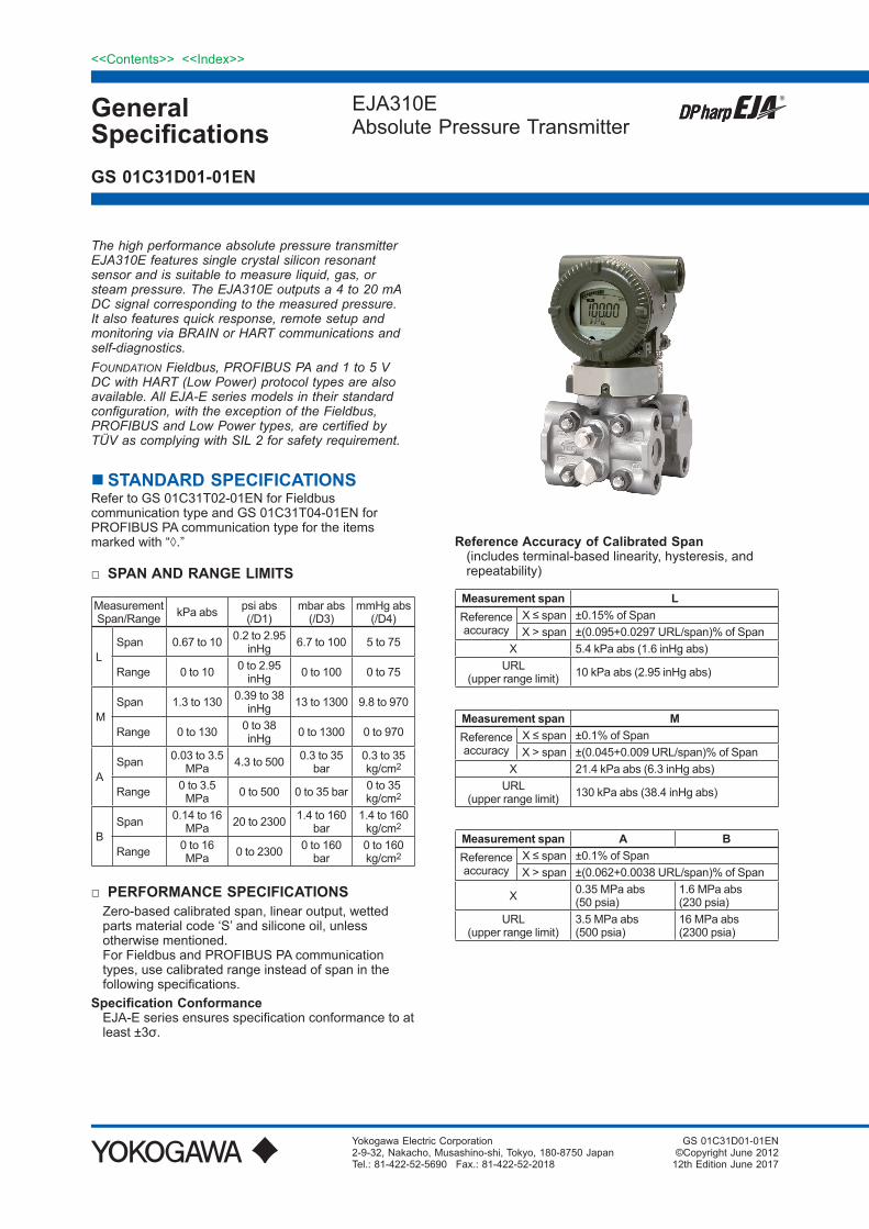
The high performance absolute pressure transmitter EJA310E features single crystal silicon resonant sensor and is suitable to measure liquid, gas, or steam pressure. The EJA310E outputs a 4 to 20 mA DC signal corresponding to the measured pressure. It also features quick response, remote setup and monitoring via BRAIN or HART communications and self-diagnostics. FOUNDATION Fieldbus, PROFIBUS PA and 1 to 5 V DC with HART (Low Power) protocol types are also available. All EJA-E series models in their standard configuration, with the exception of the Fieldbus, PROFIBUS and Low Power types, are certified by TÜV as complying with SIL 2 for safety requirement.
STANDARD SPECIFICATIONSRefer to GS 01C31T02-01EN for Fieldbus communication type and GS 01C31T04-01EN for PROFIBUS PA communication type for the items marked with “◊.”
SPAN AND RANGE LIMITS
MeasurementSpan/Range kPa abs psi abs
(/D1)mbar abs
(/D3)mmHg abs
(/D4)
LSpan 0.67 to 10 0.2 to 2.95
inHg 6.7 to 100 5 to 75
Range 0 to 10 0 to 2.95 inHg 0 to 100 0 to 75
MSpan 1.3 to 130 0.39 to 38
inHg 13 to 1300 9.8 to 970
Range 0 to 130 0 to 38 inHg 0 to 1300 0 to 970
ASpan 0.03 to 3.5
MPa 4.3 to 500 0.3 to 35 bar
0.3 to 35 kg/cm2
Range 0 to 3.5 MPa 0 to 500 0 to 35 bar 0 to 35
kg/cm2
BSpan 0.14 to 16
MPa 20 to 2300 1.4 to 160 bar
1.4 to 160 kg/cm2
Range 0 to 16 MPa 0 to 2300 0 to 160
bar0 to 160 kg/cm2
PERFORMANCE SPECIFICATIONSZero-based calibrated span, linear output, wetted parts material code ‘S’ and silicone oil, unless otherwise mentioned.For Fieldbus and PROFIBUS PA communication types, use calibrated range instead of span in the following specifications.
Specification ConformanceEJA-E series ensures specification conformance to at least ±3σ.
Reference Accuracy of Calibrated Span(includes terminal-based linearity, hysteresis, and repeatability)
Measurement span LReferenceaccuracy
X ≤ span ±0.15% of SpanX > span ±(0.095+0.0297 URL/span)% of Span
X 5.4 kPa abs (1.6 inHg abs)URL
(upper range limit) 10 kPa abs (2.95 inHg abs)
Measurement span MReferenceaccuracy
X ≤ span ±0.1% of SpanX > span ±(0.045+0.009 URL/span)% of Span
X 21.4 kPa abs (6.3 inHg abs)URL
(upper range limit) 130 kPa abs (38.4 inHg abs)
Measurement span A BReferenceaccuracy
X ≤ span ±0.1% of SpanX > span ±(0.062+0.0038 URL/span)% of Span
X 0.35 MPa abs(50 psia)
1.6 MPa abs(230 psia)
URL(upper range limit)
3.5 MPa abs(500 psia)
16 MPa abs(2300 psia)

2
All Rights Reserved. Copyright © 2012, Yokogawa Electric Corporation
<<Contents>> <<Index>>
GS 01C31D01-01EN
Ambient Temperature Effects per 28°C (50°F) Change
Capsule EffectLMA and B
±(0.12% Span + 0.35% of URL)±(0.06% Span + 0.035% of URL)±(0.06% Span + 0.012% of URL)
Stability±0.2 % of URL per 10 years
Power Supply Effects(Output signal code D and J)±0.005 % per Volt (from 21.6 to 32 V DC, 350Ω)
Vibration EffectsAmplifier housing code 1 and 3:Less than 0.1% of URL when tested per the requirements of IEC60770-1 field or pipeline with high vibration level (10-60 Hz, 0.21 mm displacement/60-2000 Hz 3 g)Amplifier housing code 2:Less than ±0.1% of URL when tested per the requirements of IEC60770-1 field with general application or pipeline with low vibration level (10-60 Hz 0.15mm displacement /60-500 Hz 2g)
Mounting Position EffectsTilting up to 90 degree will cause zero shift up to 0.5 kPa (2.0 inH2O) which can be corrected by the zero adjustment.
Response Time (All capsules) “◊”90 msWhen amplifier damping is set to zero and including dead time of 45 ms (nominal)
Minimum Pressure at Calibration*L capsule: 130 Pa abs (1 mmHg abs)M, A and B capsules: 2.7 kPa abs (20 mmHg abs)
* : If one or two of the calibration points are smaller than the above value, the above pressure is used for testing.
In case all of the calibration points are greater than the limit, only the pressure of upper range value (URV) is applied for testing.
Specifying option code /S1 with M or A capsule will lower the limit to 130 Pa abs.
/S1 is recommended for M capsule when the specified upper range value (URV) is not exceeding 3.4 kPa abs.
FUNCTIONAL SPECIFICATIONSOutput “◊”
For 4 to 20 mA HART / BRAIN (Output signal code D and J)Two wire 4 to 20 mA DC output with digital communications, linear or square root programmable. BRAIN or HART FSK protocol are superimposed on the 4 to 20 mA signal.Output range: 3.6 mA to 21.6 mAOutput limits conform to NAMUR NE43 can be preset by option C2 or C3.For 1 to 5 V HART (Output signal code Q)Three or four wire low power 1 to 5 V DC output with HART, linear or square root programmable. HART protocol are superimposed on the 1 to 5 V DC signal.Output range: 0.9 V to 5.4 V DC
Failure Alarm For 4 to 20 mA HART / BRAIN (Output signal code D and J)Output status at CPU failure and hardware error;
Up-scale: 110%, 21.6 mA DC or more (standard)Down-scale: −5%, 3.2 mA DC or less
For 1 to 5 V HART (Output signal code Q)Analog output status at CPU failure and hardware error;
Up-scale: 110%, 5.4 V DC or more (standard) Down-scale: −5%, 0.8 V DC or less
Damping Time Constant (1st order)Amplifier damping time constant is adjustable from 0.00 to 100.00 s by software and added to response time.
Note: For BRAIN protocol type, when software damping is set to less than 0.5 s, communication may occasionally be unavailble during the operation, especially while output changes dynamically. The default setting of damping ensures stable communication.
Update Period “◊”Pressure: 45 ms
Zero Adjustment LimitsZero can be fully elevated or suppressed, within the lower and upper range limits of the capsule.
External Zero Adjustment “◊”External zero is continuously adjustable with 0.01% incremental resolution of span. Re-range can be done locally using the digital indicator with rangesetting switch.
Integral Indicator (LCD display) “◊”5-digit numerical display, 6-digit unit display and bar graph.The indicator is configurable to display one or up to three of the following variables periodically.;pressure in %, scaled pressure, measured pressure.See also “Factory Setting”.
Local Parameter Setting (Output signal code D, J and Q)Parameter configuration by the external zero adjustment screw and push button (Integral indicator code E) offers easy and quick setup for parameters of Tag number, Unit, LRV, URV, Damping, Output mode (linear/square root), Display out 1, and Re-range by applying actual pressure (LRV/URV).
Burst Pressure Limits69 MPa (10,000 psi)
Self DiagnosticsCPU failure, hardware failure, configuration error, process alarm for pressure or capsule temperature.User-configurable process high/low alarm for pressure is also available.
Signal Characterizer (Output signal code D, J and Q)User-configurable 10-segment signal characterizer for 4 to 20 mA output.
SIL CertificationThe EJA-E series transmitters except Fieldbus, PROFIBUS PA and 1-5V DC with HART (Low Power) communication types are certified according to the following standards;IEC 61508: 2010; Part1 to Part 7Functional Safety of Electrical/electronic/programmable electronic related systems; SIL 2 capability for single transmitter use, SIL 3 capability for dual transmitter use.
Feb. 10, 2017-00

3<<Contents>> <<Index>>
All Rights Reserved. Copyright © 2012, Yokogawa Electric Corporation GS 01C31D01-01EN
NORMAL OPERATING CONDITION (Optional features or approval codes may affect limits.)
Ambient Temperature Limits−40 to 85°C (−40 to 185°F)−30 to 80°C (−22 to 176°F) with LCD display
Process Temperature Limits−40 to 120°C (−40 to 248°F) M, A & B capsules−40 to 100°C (−40 to 212°F) L capsule
Ambient Humidity Limits0 to 100% RH
Maximum Over Pressure
Capsule PressureL and MAB
500 kPa abs (72 psia)16 MPa abs (2300 psia)25 MPa abs (3600 psia)
Working Pressure Limits (Silicone oil) Maximum Pressure Limits
Capsule PressureLMAB
10 kPa abs (2.95 inHg abs)130 kPa abs (38 inHg abs)3.5 MPa abs (500 psia)16 MPa abs (2300 psia)
Minimum Pressure LimitSee graph below
-40(-40)
0(32)
40(104)
80(176)
120 (248)
0.1(0.75) 0.13(1)
1(7.5)
100(750)
10(75)
2.7(20)
0.46(3.45)
0.01(0.075) 0.013(0.1)
85 (185)
(mmHg abs)
WorkingpressurekPa abs
Applicable range
Process temperature °C(°F)
M, A and B capsule
L capsule
F01E.ai
Figure 1. Working Pressure and Process Temperature
Supply & Load Requirements (Output signal code D and J. Optional features or approval codes may affect electrical requirements.)With 24 V DC supply, up to a 550Ω load can beused. See graph below.
E-10.5 0.0244
(Ω)
Power supply voltage E (V DC)
600
250
R
10.5 16.6 25.2 42
Externalloadresistance
DigitalCommunication
rangeBRAIN and HART
R=
F02E.ai
Figure 2. Relationship Between Power Supply Voltage and External Load Resistance (Output signal code D and J)
Supply Voltage “◊” For 4 to 20 mA HART / BRAIN (Output signal code D and J)10.5 to 42 V DC for general use and flameproof type.10.5 to 32 V DC for lightning protector
(option code /A.)10.5 to 30 V DC for intrinsically safe, type n, or non-
incendive.Minimum voltage limited at 16.6 V DC for digital
communications, BRAIN and HARTFor 1 to 5 V HART (Output signal code Q)Power supply :9 to 28 V DC for general use and flame proof type. Power Consumption : 0.96 mA to 3 mA, 27 mW
Load for 4 to 20 mA HART / BRAIN (Output signal code D and J)
0 to 1290Ω for operation250 to 600Ω for digital communication
Output Load for 1 to 5 V HART (Output signal code Q)
1 MΩ or greater (meter input impedance)Note that with three-wire connection, the cable length may affect the measurement accuracy of the output signal.
Communication Requirements “◊” (Approval codes may affect electrical requirements.)
BRAIN Communication Distance
Up to 2 km (1.25 miles) when using CEV polyethylene-insulated PVC-sheathed cables. Communication distance varies depending on type of cable used.
Load Capacitance0.22 µF or less
Load Inductance3.3 mH or less
Oct. 24, 2014-00
4
All Rights Reserved. Copyright © 2012, Yokogawa Electric Corporation
<<Contents>> <<Index>>
GS 01C31D01-01EN
Input impedance of communicating device10 kΩ or more at 2.4 kHz.
EMC Conformity StandardsEN 61326-1 Class A, Table2EN 61326-2-3EN 61326-2-5 (for fieldbus)
European Pressure Equipment Directive 2014/68/EUSound Engineering Practice (for all capsules)
EU RoHS DirectiveEN 50581
Safety Requirement StandardsEN 61010-1, C22.2 No.61010-1• Installation category: I
(Anticipated transient overvoltage 330 V)• Pollution degree: 2• Indoor/Outdoor use
PHYSICAL SPECIFICATIONSWetted Parts Materials Diaphragm, Cover Flange, Process Connector,
Capsule Gasket, and Vent/Drain PlugRefer to “MODEL AND SUFFIX CODES.”
Process Connector GasketPTFE TeflonFluorinated rubber for option code N2 and N3
Non-wetted Parts Materials Bolting
B7 carbon steel, 316L SST or 660 SST Housing
• Low copper cast aluminum alloy• Low copper cast aluminum alloy with corrosion
resistance properties (copper content ≤ 0.03%, iron content ≤ 0.15%) (optional)
• ASTM CF-8M Stainless steel (optional) Coating of housing
[for aluminum housing]Urethane curing type polyester resin powder coating Deep sea moss green paint (Munsell 0.6GY3.1/2.0 or its equivalent)[for option code /P or /X2]Epoxy and polyurethane resin solvent coating
Degrees of protectionIP66/IP67, Type 4X
Cover O-ringsBuna-N, fluoro-rubber (optional)
Name plate and tag316 SST
Fill fluidSilicone, Fluorinated oil (optional)
Weight[Installation code 7, 8, and 9]2.8 kg (6.2 lb) without integral indicator, mounting bracket, and process connector.Add 1.5 kg (3.3 lb) for Amplifier housing code 2.
ConnectionsRefer to “MODEL AND SUFFIX CODES.”Process connection of cover flange: IEC61518
June 1, 2017-00
< Related Instruments>FieldMate Versatile Device Management Wizard:
Refer to GS 01R01A01-01E.BRAIN TERMINAL: Refer to GS 01C00A11-00EPower Distributor: Refer to GS 01B04T01-02E or
GS 01B04T02-02E
< Reference >• is a registered trademark of Yokogawa
Electric Corporation.• FieldMate; Trademark of Yokogawa Electric
Corporation.• Teflon; Trademark of E.I. DuPont de Nemours &
Co.• Hastelloy; Trademark of Haynes International Inc.• HART®: Registered trademark of the FieldComm
Group.• FOUNDATION Fieldbus; Trademark of the
FieldComm Group.• PROFIBUS; Registered trademark of Profibus
Nutzerorganisation e.v., Karlsruhe, Germany.Other company names and product names used in this material are registered trademarks or trademarks of their respective owners.

5<<Contents>> <<Index>>
All Rights Reserved. Copyright © 2012, Yokogawa Electric Corporation GS 01C31D01-01EN
MODEL AND SUFFIX CODESModel Suffix Codes Description
EJA310E . . . . . . . . . . . . . . . . . . . . . . . . . . . . . . . Absolute pressure transmitterOutput signal -D . . . . . . . . . . . . . . . . . . . . . . . . . . . . .
-J . . . . . . . . . . . . . . . . . . . . . . . . . . . . .-F . . . . . . . . . . . . . . . . . . . . . . . . . . . . .
-G . . . . . . . . . . . . . . . . . . . . . . . . . . . . .
-Q . . . . . . . . . . . . . . . . . . . . . . . . . . . . .
4 to 20 mA DC with digital communication (BRAIN protocol)4 to 20 mA DC with digital communication (HART 5/HART 7 protocol)*1Digital communication (FOUNDATION Fieldbus protocol, refer to
GS 01C31T02-01EN)Digital communication (PROFIBUS PA protocol, refer to
GS 01C31T04-01EN)Low Power, 1 to 5 V DC with digital communication (HART 7 protocol)
Measurementspan (capsule)
L . . . . . . . . . . . . . . . . . . . . . . . . . . . .M . . . . . . . . . . . . . . . . . . . . . . . . . . .A. . . . . . . . . . . . . . . . . . . . . . . . . . . .B. . . . . . . . . . . . . . . . . . . . . . . . . . . .
0.67 to 10 kPa abs (0.2 to 2.95 inHg abs)1.3 to 130 kPa abs (0.39 to 38 inHg abs)0.03 to 3.5 MPa abs (4.3 to 500 psia)0.14 to 16 MPa abs (20 to 2300 psia)
Wetted partsmaterial *2
. . . . . . . . . . . . . . . . . . . . . . . . Refer to “Wetted Parts Material” Table.
Process connections
0 . . . . . . . . . . . . . . . . . . . . . .1 . . . . . . . . . . . . . . . . . . . . . .2 . . . . . . . . . . . . . . . . . . . . . .3 . . . . . . . . . . . . . . . . . . . . . .4 . . . . . . . . . . . . . . . . . . . . . .5 . . . . . . . . . . . . . . . . . . . . . .
without process connector (Rc1/4 female on the cover flanges)with Rc1/4 female process connectorwith Rc1/2 female process connectorwith 1/4 NPT female process connectorwith 1/2 NPT female process connectorwithout process connector (1/4 NPT female on the cover flanges)
Bolts and nuts materia J . . . . . . . . . . . . . . . . . . . .G. . . . . . . . . . . . . . . . . . . .C. . . . . . . . . . . . . . . . . . . .
B7 carbon steel316L SST660 SST
Installation
-3 . . . . . . . . . . . . . . . .-7 . . . . . . . . . . . . . . . .-8 . . . . . . . . . . . . . . . .-9 . . . . . . . . . . . . . . . .-B . . . . . . . . . . . . . . . .-U . . . . . . . . . . . . . . . .
Vertical piping, right side high pressure, and process connection down sideVertical piping, left side high pressure, and process connection down sideHorizontal piping and right side high pressureHorizontal piping and left side high pressureBottom Process Connection, left side high pressure *8Universal flange *8
Amplifier housing 1 . . . . . . . . . . . . . . .3 . . . . . . . . . . . . . . .2 . . . . . . . . . . . . . . .
Cast aluminum alloyCast aluminum alloy with corrosion resistance properties *3ASTM CF-8M stainless steel *4 *3
Electrical connection
0 . . . . . . . . . . . .2 . . . . . . . . . . . .4 . . . . . . . . . . . .5 . . . . . . . . . . . .7 . . . . . . . . . . . .9 . . . . . . . . . . . .A. . . . . . . . . . . .C. . . . . . . . . . . .D. . . . . . . . . . . .
G1/2 female, one electrical connection without blind plugs1/2 NPT female, two electrical connections without blind plugsM20 female, two electrical connections without blind plugsG1/2 female, two electrical connections and a blind plug *51/2 NPT female, two electrical connections and a blind plug *5M20 female, two electrical connections and a blind plug *5G1/2 female, two electrical connections and a 316 SST blind plug1/2 NPT female, two electrical connections and a 316 SST blind plugM20 female, two electrical connections and a 316 SST blind plug
Integral indicator
D. . . . . . . . .E . . . . . . . . .N. . . . . . . . .
Digital indicator *6Digital indicator with the range setting switch (push button) *7(None)
Mounting bracket B. . . . . .D. . . . . .J . . . . . .K. . . . . .M . . . . . N. . . . . .
304 SST 2-inch pipe mounting, flat type (for horizontal piping)304 SST or SCS13A 2-inch pipe mounting, L type (for vertical piping)316 SST 2-inch pipe mounting, flat type (for horizontal piping)316 SST or SCS14A 2-inch pipe mounting, L type (for vertical piping)316 SST or SCS14A 2-inch pipe mounting (for bottom process connection type)(None)
Optional Codes / Optional specification
The “” marks indicate the most typical selection for each specification.*1: HART 5 or HART 7 is selectable. Specify upon ordering.*2: Users must consider the characteristics of selected wetted parts material and influence of process fluids. Specifying
inappropriate materials has the potential to cause serious damage to human body and plant facilities resulted from an unexpected leak of the corrosive process fluids.
*3: Not applicable for electrical connection code 0, 5, 7, 9 and A.*4: Not applicable for electrical connection code 0, 5, 7 and 9.*5: Material of a blind plug; aluminum alloy for code 5 and 9, and SUS304 for code 7.*6: Not applicable for output signal code G.*7: Not applicable for output signal code F.*8: Applicable only for wetted parts material code S.
June 1, 2017-00
6
All Rights Reserved. Copyright © 2012, Yokogawa Electric Corporation
<<Contents>> <<Index>>
GS 01C31D01-01EN
Table. Wetted Parts MaterialsWetted parts material code
Cover flange and process connector Capsule Capsule gasket Vent/Drain plug
S # ASTM CF-8M *1 Hastelloy C-276 *2 (Diaphragm)F316L SST, 316L SST (Others) Teflon-coated 316L SST 316 SST
L # ASTM CF-3M *3 Hastelloy C-276 *2 (Diaphragm)F316L SST, 316L SST (Others) Teflon-coated 316L SST 316L SST
*1: Cast version of 316 SST. Equivalent to SCS14A.*2: Hastelloy C-276 or ASTM N10276.*3: Cast version of 316L SST. Equivalent to SCS16A.The ‘#’marks indicate the construction materials conform to NACE material recommendations per MR0175/ISO15156. Please refer to the latest standards for details. Selected materials also conform to NACE MR0103.
OPTIONAL SPECIFICATIONS (For Explosion Protected type) “◊”For other agency approvals and marine approvals, please refer to GS 01C25A20-01EN.
Item Description CodeFactory Mutual(FM)
FM Explosionproof Approval *1Applicable Standard: FM3600, FM3615, FM3810, ANSI/NEMA 250Explosionproof for Class I, Division 1, Groups B, C and D, Dust-ignitionproof for Class II/III, Division 1,Groups E, F and G, in Hazardous locations, indoors and outdoors (Enclosure: Type 4X)“FACTORY SEALED, CONDUIT SEAL NOT REQUIRED.”Temperature class: T6, Amb. Temp.: –40 to 60°C (–40 to 140°F)
FF1
FM Intrinsically safe Approval *1*3
Applicable Standard: FM3600, FM3610, FM3611, FM3810Intrinsically Safe for Class I, Division 1, Groups A, B, C & D, Class II, Division 1,Groups E, F & G and Class III, Division 1, Class I, Zone 0, in Hazardous Locations, AEx ia IICNonincendive for Class I, Division 2, Groups A, B, C & D, Class II, Division. 2,Groups F & G, Class I, Zone 2, Group IIC, in Hazardous LocationsEnclosure: Type 4X, Temp. Class: T4, Amb. Temp.: –60 to 60°C (–75 to 140°F)Intrinsically Safe Apparatus Parameters[Groups A, B, C, D, E, F and G] Vmax=30 V, Imax=200 mA, Pmax=1 W, Ci=6 nF, Li=0 µH[Groups C, D, E, F and G] Vmax=30 V, Imax=225 mA, Pmax=1 W, Ci=6 nF, Li=0 µH
FS1
Combined FF1 and FS1 *1*3 FU1ATEX ATEX Flameproof Approval *1
Applicable Standard: EN 60079-0:2012+A11:2013, EN 60079-1:2007 (“2014” from August 1, 2017), EN 60079-31:2014Certificate: KEMA 07ATEX0109 XII 2G, 2D Ex d IIC T6...T4 Gb (“Ex db IIC T6...T4 Gb” from August 1, 2017), Ex tb IIIC T85°C DbDegree of protection: IP66/IP67Amb. Temp. (Tamb) for gas-proof :T4; –50 to 75°C (–58 to 167°F), T5; –50 to 80°C (–58 to 176°F), T6; –50 to 75°C (–58 to 167°F) Process Temp. for gas-proof (Tp):T4; –50 to 120°C (–58 to 248°F), T5; –50 to 100°C (–58 to 212°F), T6; –50 to 85°C (–58 to 185°F)Max. surface Temp. for dust-proof: T85°C (Tamb: –30 to 75°C, Tp: –30 to 85°C) *2
KF22
ATEX Intrinsically safe Approval *1*3
Applicable Standard: EN 60079-0:2012+A11:2013, EN 60079-11:2012Certificate: DEKRA 11ATEX0228 XII 1G, 2D Ex ia IIC T4 Ga, Ex ia IIIC T85°C T100°C T120°C DbDegree of protection: IP66/IP67Amb. Temp. (Tamb) for EPL Ga: –50 to 60°C (–58 to 140°F) Maximum Process Temp. (Tp) for EPL Ga:120°CElectrical data: Ui=30 V, Ii=200 mA, Pi=0.9 W, Ci=27.6 nF, Li=0 µHAmb. Temp. for EPL Db: –30 to 60°C *2Max. surface Temp. for EPL Db: T85°C (Tp: 80°C), T100°C (Tp: 100°C), T120°C (Tp: 120°C)
KS21
Combined KF22, KS21 and ATEX Intrinsically safe Ex ic *1*3
[ATEX Intrinsically safe Ex ic] Applicable Standard: EN 60079-0:2012+A11:2013, EN 60079-11:2012 II 3G Ex ic IIC T4 Gc, Amb. Temp.: –30 to 60°C (–22 to 140°F) *2Ui=30 V, Ci=27.6 nF, Li=0 μH
KU22
June 1, 2017-00

7<<Contents>> <<Index>>
All Rights Reserved. Copyright © 2012, Yokogawa Electric Corporation GS 01C31D01-01EN
Item Description CodeCanadianStandardsAssociation(CSA)
CSA Explosionproof Approval *1Certificate: 2014354Applicable Standard: C22.2 No.0, C22.2 No.0.4, C22.2 No.0.5, C22.2 No.25, C22.2 No.30,C22.2 No.94, C22.2 No.60079-0, C22.2 No.60079-1, C22.2 No.61010-1, C22.2 No.61010-2-030Explosion-proof for Class I, Groups B, C and D.Dustignition-proof for Class II/III, Groups E, F and G.When installed in Division 2, “SEAL NOT REQUIRED” Enclosure: Type 4X, Temp. Code: T6...T4Ex d IIC T6...T4 Enclosure: IP66/IP67Max.Process Temp.: T4;120°C(248°F), T5;100°C(212°F), T6; 85°C(185°F)Amb.Temp.: –50 to 75°C(–58 to 167°F) for T4, –50 to 80°C(–58 to 176°F) for T5, –50 to 75°C(–58 to 167°F) for T6 *2
Process Sealing CertificationDual Seal Certified by CSA to the requirement of ANSI/ISA 12.27.01No additional sealing requiredPrimary seal failure annunciation: at the zero adjustment screw
CF1
CSA Intrinsically safe Approval *1*3
Certificate: 1606623[For CSA C22.2]
Applicable Standard: C22.2 No.0, C22.2 No.0.4, C22.2 No.25, C22.2 No.94, C22.2 No.157, C22.2 No.213, C22.2 No.61010-1, C22.2 No.60079-0, C22.2 No.61010-2-030Intrinsically Safe for Class I, Division 1, Groups A, B, C & D, Class II, Division 1, Groups E, F & G,Class III, Division 1, Nonincendive for Class I, Division 2, Groups A, B, C & D, Class II, Division 2,Groups F & G, Class III, Division 1Enclosure: Type 4X, Temp. Code: T4 Amb. Temp.: –50 to 60°C(–58 to 140°F) *2Electrical Parameters: [Intrinsically Safe] Vmax=30V, Imax=200mA, Pmax=0.9W, Ci=10nF, Li=0 µH[Nonincendive] Vmax=30V, Ci=10nF, Li=0 µH
[For CSA E60079]Applicable Standard: CAN/CSA E60079-11, CAN/CSA E60079-15, IEC 60529:2001Ex ia IIC T4, Ex nL IIC T4 Enclosure: IP66/IP67Amb. Temp.: –50 to 60°C(–58 to 140°F) *2, Max. Process Temp.: 120°C(248°F)Electrical Parameters: [Ex ia] Ui=30V, Ii=200mA, Pi=0.9W, Ci=10nF, Li=0 µH [Ex nL] Ui=30V, Ci=10nF, Li=0 µH
Process Sealing CertificationDual Seal Certified by CSA to the requirement of ANSI/ISA 12.27.01No additional sealing requiredPrimary seal failure annunciation: at the zero adjustment screw
CS1
Combined CF1 and CS1 *1*3 CU1IECEx IECEx Flameproof Approval *1
Applicable Standard: IEC 60079-0:2011, IEC60079-1:2007-4Certificate: IECEx CSA 07.0008Flameproof for Zone 1, Ex d IIC T6...T4 Gb Enclosure: IP66/IP67Max.Process Temp.: T4;120°C(248°F), T5;100°C(212°F), T6; 85°C(185°F)Amb.Temp.: –50 to 75°C(–58 to 167°F) for T4, –50 to 80°C(–58 to 176°F) for T5,–50 to 75°C(–58 to 167°F) for T6
SF2
IECEx Intrinsically safe and Flameproof Approval *1*3
Intrinsically safe Ex iaCertificate: IECEx DEK 11.0081X Applicable Standard: IEC 60079-0:2011, IEC 60079-11:2011Ex ia IIC T4 Ga Enclosure: IP66/IP67Amb. Temp.: –50 to 60 °C(–58 to 140 °F), Max. Process Temp.: 120 °C(248 °F)Electrical Parameters: Ui=30 V, Ii=200 mA, Pi=0.9 W, Ci=27.6 nF, Li=0 μH
Intrinsically safe Ex icCertificate: IECEx DEK 13.0061X Applicable Standard: IEC 60079-0:2011, IEC 60079-11:2011Ex ic IIC T4 Gc IP code: IP66Amb. Temp.: –30 to 60°C(–22 to 140°F) *2, Max. Process Temp.: 120°C(248°F)Electrical Parameters: Ui=30V,Ci=27.6 nF, Li=0 μH
FlameproofCertificate: IECEx CSA 07.0008Applicable Standard: IEC 60079-0:2011, IEC60079-1:2007-4Flameproof for Zone 1, Ex d IIC T6...T4 Gb Enclosure: IP66/IP67Max.Process Temp.: T4;120°C(248°F), T5;100°C(212°F), T6; 85°C(185°F)Amb.Temp.: –50 to 75°C(–58 to 167°F) for T4, –50 to 80°C(–58 to 176°F) for T5,–50 to 75°C(–58 to 167°F) for T6
SU21
*1: Applicable for Electrical connection code 2, 4, 7, 9, C and D.*2: Lower limit of ambient temperature is –15°C (5°F) when /HE is specified.*3: Not applicable for output signal code Q.
June 1, 2017-00

8
All Rights Reserved. Copyright © 2012, Yokogawa Electric Corporation
<<Contents>> <<Index>>
GS 01C31D01-01EN
OPTIONAL SPECIFICATIONSItem Description Code
Painting Color change Amplifier cover only*1 PAmplifier cover and terminal cover, Munsell 7.5 R4/14 PR
Coating change Anti-corrosion coating*2 X2316 SST exterior parts 316 SST zero-adjustment screw and setscrews*3 HCFluoro-rubber O-ring All O-rings of amplifier housing. Lower limit of ambient temperature: –15°C (5°F) HELightning protector Transmitter power supply voltage: 10.5 to 32 V DC (10.5 to 30 V DC for intrinsically safe type.)
Allowable current: Max. 6000 A (1×40 µs), Repeating 1000 A (1×40 µs) 100 timesApplicable Standards: IEC 61000-4-4, IEC 61000-4-5
A
Oil-prohibited use*5 Degrease cleansing treatment K1Degrease cleansing treatment with fluorinated oilfilled capsule.Operating temperature −20 to 80°C (−4 to 176°F) K2
Oil-prohibited use with dehydrating treatment*5
Degrease cleansing and dehydrating treatment K5Degrease cleansing and dehydrating treatment with fluorinated oilfilled capsule.Operating temperature −20 to 80°C (−4 to 176°F) K6
Capsule fill fluid Flourinated oil filled in capsuleOperating temperature −20 to 80°C (−4 to 176°F) K3
Calibration units*6 P calibration (psi unit)(See Table for Span and Range Limits.)
D1bar calibration (bar unit) D3M calibration (kgf/cm2 unit) D4
Long vent*7 Total length: 119 mm (standard: 34 mm); Total length when combining with Optional code K1, K2, K5, and K6: 130 mm. Material: 316SST. U1
Gold-plated capsule gasket *4 Gold-plated 316L SST capsule gasket. Without drain and vent plugs. GSGold-plated diaphragm *21 Surface of isolating diaphragms are gold plated, effective
for hydrogen permeation.Gold plate thickness: 3 μm A1Gold plate thickness: 10 μm A2
Output limits and failure option*8
Output status at CPU failure and hardware error.When combining with Optional code F1, output signal is −5%, 3.2 mA DC or less for 4 to 20 mA output type, and −5%, 0.8V DC or less for 1 to 5 V output type.
C1
NAMUR NE43 Compliant Output signal limits: 3.8 mA to 20.5 mA *20
Failure alarm down-scale: Output status at CPUfailure and hardware error is −5%, 3.2 mA DC or less. C2
Failure alarm up-scale: Output status at CPUfailure and hardware error is 110%, 21.6 mA or more. C3
130 Pa abs (1 mmHg abs) Calibration *11 Minimum input pressure: 130 Pa abs(1 mmHg abs) at range calibrating testing S1
Body option*9
HL
TerminalSide
F03E.ai
Without drain and vent plugs N1
N1 and Process connection, based on IEC61518 with female thread on both sides of cover flange, with blind kidney flanges on back N2
N2, and Material certificate for cover flange, diaphragm, capsule body, and blind kidney flange N3
Wired tag plate 316 SST tag plate wired onto transmitter N4Data configuration at factory*10
Data configuration for HART communication type Software damping, Descriptor, Message CA
Data configuration for BRAIN communication type Software damping CBMaterial certificate*12 Cover flange *14 M01
Cover flange, Process connector *15 M11Pressure test/Leak test certificate*13
Test Pressure: 50 kPa (200 inH2O)*16Nitrogen(N2) Gas*19
Retention time: one minute
T04Test Pressure: 3.5MPa (500 psi)*17 T01Test Pressure: 16 MPa (2300 psi)*18 T12
Feb. 10, 2017-00
9<<Contents>> <<Index>>
All Rights Reserved. Copyright © 2012, Yokogawa Electric Corporation GS 01C31D01-01EN
*1: Not applicable for amplifier housing code 2 and 3.*2: Not applicable with color change option. Not applicable for amplifier housing code 2.*3: 316 or 316L SST. The specification is included in amplifier code 2.*4: Applicable for wetted parts material code S; process connection code 0 and 5; and installation code 8 and 9. Not applicable
for option code U1, N2, N3 and M11. No PTFE is used for wetted parts.*5: Applicable for wetted parts material code S.*6: The unit of MWP (Max. working pressure) on the name plate of a housing is the same unit as specified by option code D1,
D3, and D4.*7: Applicable for vertical impulse piping type (Installation code 7) and wetted parts material code S. Long vent material is 316
SST.*8: Applicable for output signal code D and J. The hardware error indicates faulty amplifier or capsule.*9: Applicable for wetted parts material code S, process connection code 3, 4, and 5; Installation code 9; and mounting bracket
code N. Process connection faces on the other side of zero adjustment screw.*10: Also see ‘Ordering Instructions’.*11: Applicable for Capsule code M and A with upper range value smaller than 53.3 kPa (400 mmHg abs) . If not specified, minimum input pressure for calibration testing will be 2.7 kPa abs (20 mmHg abs) even if the smaller range
value is specified for customer’s range.*12: Material traceability certification per EN 10204 3.1B.*13: The unit on the certificate is always Pa unit regardless of selection of option code D1, D3 or D4.*14: Applicable for Process connections code 0 and 5.*15: Applicable for Process connections code 1, 2, 3, and 4.*16: Applicable for capsule code M and L.*17: Applicable for capsule code A.*18: Applicable for capsule code B.*19: Pure nitrogen gas is used for oil-prohibited use (option codes K1, K2, K5, and K6.)*20: The 1 to 5 V voltage output corresponding to 4 to 20 mA current output is applied to output signal code Q which is non-
compliant to NAMUR NE43.*21: /A2 is not applicable with FM approval.
F04E.ai
SUPPLY
CHECK
+–+–
Power supply and output terminals
External indicator (ammeter) terminals*1*2
*1: When using an external indicator or check meter, the internal resistance must be 10 Ω or less. *2: Not available for FOUNDATION Fieldbus and PROFIBUS PA communication types.
Terminal Configuration
Ground terminal
1Terminal
12
23
SUPPLY
VOUT
+–+–
Power supply terminals
Terminal Wiring for 1 to 5 V output
Ground terminal
12
23
2Terminal 3Terminal
1 to 5 V DC with HART communication terminals
Terminal Wiring for 4 to 20 mA output, FOUNDATION Fieldbus and PROFIBUS PA communication types
Three or four wire connection. For four wire connection, both supply and signal lines use SUPPLY - terminal.
June 1, 2017-00

10
All Rights Reserved. Copyright © 2012, Yokogawa Electric Corporation
<<Contents>> <<Index>>
GS 01C31D01-01EN June 1, 2017-00
DIMENSIONSUnit: mm (approx.inch)
Vertical Impulse Piping Type (INSTALLATION CODE ‘7’) (For code ‘3’, refer to the notes below.)
95(3
.74)
242(9.53)175(6.89)129(5.08)97
(3.82)
223(
8.78
)
52(2
.05)
97(3
.82)
41 (1.6
1)
67(2
.64)
Electrical connectionfor code 5, 9, A, and D.
(optional)
Extenal indicatorConduit connection
Integral indicator (optional)
Zero adjustmentGround terminal
(optional)
Mounting bracket(L-type,optional)
Process connectionConduitconnection
110(4.33)
ø78(
3.07
)
ø70(
2.76
)
39(1.54)
12(0.47)
138(
5.43
)*2
27(1.06)
54(2
.13)
2-inch pipe(O.D. 60.5 mm)
Vent/Drain plugs
6(0
.24)
Highpressure side*1
Lowpressure side*1
Processconnector
F05E.ai
41.3(1.63)
Horizontal Impulse Piping Type (INSTALLATION CODE ‘9’) (For CODE ‘8’, refer to the notes below.)
54(2.13)
6(0.24)
175(
6.89
)
145(
5.71
)12
4(4.
88)
47(1
.85)
95(3.74)
89(3.50)
115(4.53)
41(1.61)
110(4.33)12
(0.47)39
(1.54)
ø70
(2.7
6)12
9(5.
08)
ø78(
3.07
)
65*2
(2.56)
67(2.64)
Drain plug*3
2-inch pipe(O.D. 60.5 mm)
Vent plug*3
Zeroadjustment
Ground terminal
Mounting bracket(Flat-type,optional)
Electrical connectionfor code 5, 9, A, and D.
Conduit connection
(optional)
Extenal indicatorConduit connection Integral indicator
(optional)
(optional)
Processconnection 27(1.06)
Lowpressure side*1
Highpressure side*1
Process connector
Vent plug,Drain plug*3
F06E.ai
41.3
(1.6
3)
*1: When Installation code 3 or 8 is selected, high and low pressure side on above figure are reversed. (i.e. High pressure side is on the right side.)*2: When option code K1, K2, K5 or K6 is secified, add 15mm(0.59 inch) to the value in the figure.*3: Not available when option code GS is selected.*4: When electrical connection code 7 or C is selected, a blind plug is protruded upto 8 mm from the conduit connection.

11<<Contents>> <<Index>>
All Rights Reserved. Copyright © 2012, Yokogawa Electric Corporation GS 01C31D01-01EN June 1, 2017-00
Unit: mm (approx.inch)
Universal Flange (INSTALLATION CODE ‘U’)
54(2.13)
6(0.24)
ø78(
3.07
)
ø70
(2.7
6)
Integral indicator (optional)
Ground terminal
ZeroadjustmentExternal indicator
Conduit connection(optional)
Vent plug
Vent plug
Process connectionProcess connector (optional)
Conduit connection
Lowpressure side
Highpressure side
Electrical connectionfor code 5, 9, A, and D.
Drain plug
Drain plug
Drain plug65*1
(2.56)
110(4.33)
12(0.47)
39(1.54)
115(4.53)
41(1.61)
58(2.28)
67(2.64)
175(
6.89
)
129(
5.08
)
145(
5.71
)
95(3.74)
F07E.ai
41.3
(1.6
3)
*1: When Option code K1, K2, K5, or K6 is selected, add 15 mm(0.59 inch) to the value.*2: When electrical connection code 7 or C is selected, a blind plug is protruded upto 8 mm from the conduit connection.
Bottom Process Connection Type (INSTALLATION CODE ‘B’)
54(2.13)
6(0.24)
129(5.08)
65(2.56)
27(1.06)
ø78(
3.07
)
ø70
(2.7
6)
39(1.54)
12(0.47)
110(4.33)
188(7.40)95(3.74)73
(2.87)
109(
4.29
)
159(
6.26
)
Integral indicator (optional)
Ground terminal
Zeroadjustment
Extenal indicatorConduit connection(optional)
Vent plug
2-inch pipe(O.D. 60.5 mm)
Mounting bracket*1
(optional)
Process connection
Conduit connection
Lowpressure side
Highpressure side
Electrical connectionfor code 5, 9, A, and D.
Process connector(optional)
60(2
.36)
F08E.ai
41.3(1.63)
*1: A transmitter with SST housing is not applicable for mounting to horizontal 2-inch pipe.*2: When electrical connection code 7 or C is selected, a blind plug is protruded upto 8 mm from the conduit connection.

12
All Rights Reserved. Copyright © 2012, Yokogawa Electric Corporation
<<Contents>> <<Index>>
GS 01C31D01-01ENSubject to change without notice.
Feb. 28, 2014-00
< Ordering Information > “◊”Specify the following when ordering1. Model, suffix codes, and option codes2. Calibration range and units:
1) Calibration range can be specified with range value specifications up to 5 digits (excluding any decimal point) for low or high range limits within the range of -32000 to 32000. When reverse range is designated, specify Lower Range Value(LRV) as greater than Upper Range Value(URV).
2) Specify only one unit from the table, ‘Factory setting.’
3. Display scale and units (for transmitters equipped with an integral indicator only)
Specify either 0 to 100% or engineering unit scale and ‘Range and Unit’ for engineering units scale:
Scale range can be specified with range limit specifications up to 5 digits (excluding any decimal point) for low or high range limits within the range of -32000 to 32000. Unit display consists of 6-digit, therefore, if specified unit excluding ‘/’ is longer than 6 characters, the first 6 characters will be displayed on the unit display.
4. HART PROTOCOL When output signal code is “J”, specify the HART
protocol revision “5” or “7”.5. TAG NO (if required) Specified characters (up to 16 characters for
BRAIN, 22 characters for HART) are engraved on the stainless steel tag plate fixed on the housing.
6. SOFTWARE TAG (for HART only. if required) Specified characters (up to 32 characters) are set
as “Tag” (the first 8 characters) and “Long tag”*1 (32 characters) in the amplifier memory. Use alphanumeric capital letters.
When the “SOFTWARE TAG” is not specified, specified “TAG NO” is set as “Tag” (the first 8 characters) and “Long tag”*1 (22 characters) in the amplifier memory.*1: applicable only when HART 7 is selected.
7. Other factory configurations (if required) Specifying option code CA or CB will allow further configuration at factory. Following are configurable items and setting range.
[/CA : For HART communication type]1) Descriptor (up to 16 characters)2) Message (up to 30 characters)3) Software damping in second (0.00 to 100.00)
[/CB : For BRAIN communication type]1) Software damping in second (0.00 to 100.00)
< Factory Setting > “◊”
Tag number As specified in orderSoftware damping *1 ‘2.00 s’ or as specified in order
Calibration range lower range value As specified in order
Calibration range upper range value
As specified in order
Calibration range units
Selected from torr, Pa abs *2, hPa abs *2,kPa abs, MPa abs, mbar abs, bar abs,mmH2O abs, mmH2O(68°F) abs,mmHg abs, gf/cm2 abs, kgf/cm2 abs,inH2O abs, inH2O abs(68°F), inHg abs,ftH2O abs, ftH2O abs(68°F) , atm, or psia.(Only one unit can be specified)
Display setting Designated value specified in order.(%, or user scaled value.)
*1: To specify this item at factory, option code CA or CB is required.
*2: Not available for HART protocol type.
< Material Cross Reference >
ASTM JIS316 SUS316F316 SUSF316316L SUS316LF316L SUSF316L304 SUS304F304 SUSF304660 SUH660B7 SNB7CF-8M SCS14A


![Profibus PA Fieldbus Display [ Revision 2 ] and Fieldbus ... Instruments... · Profibus PA Fieldbus Display [ Revision 2 ] and Fieldbus Indicator Fieldbus Interface Guide. ... Siemens](https://img.dokumen.tips/doc/110x75/5b2fe38e7f8b9ae16e8da83d/profibus-pa-fieldbus-display-revision-2-and-fieldbus-instruments.jpg)