Embed Size (px)
Citation preview

MAINTENANCE MANUAL
Edition october/11
Drivelines
MM-0998

MAINTENANCE MANUAL
Index
1 - Drivelines ............................................................................................................ 03
2 - Introduction ......................................................................................................... 05
3 - Removal and Disassembly ................................................................................. 06
4 - Assembly and Installation ................................................................................... 08
5 - Lubrication .......................................................................................................... 11

Service Notes
2 MAINTENANCE MANUAL
About This ManualThis manual provides service and repair proce-dures for MeritorXtended Lube MXL™ 17N, 176N and 18N Se-ries drivelines.
Before You Begin1. Read and understand all instructions and pro-
cedures before you begin to service compo-nents.
2. Read and observe all Warning and Caution hazard alert messages in this publication. They provide information that can help pre-vent serious personal injury, damage to com-ponents, or both.
3. Follow your company’s maintenance and ser-vice, installation, and diagnostics guidelines.
4. Use special tools when required to help avoid serious personal injury and damage to com-ponents.
Hazard Alert Messages and Tor-que Symbols
WARNINGA Warning alerts you to an instruction or pro-cedure that you must follow exactly to avoid serious personal injury and damage to compo-nents.
CAUTIONA Caution alerts you to an instruction or proce-dure that you must follow exactly to avoid da-mage to components.
This symbol alerts you to tighten fasteners to a specified torque value.
How to Obtain Additional Mainte-nance and Service Information for Meritor MXL™ 17N, 176N and 18N Series Easy Service™ and Full--Round Drivelines
Refer to Maintenance Manual MM-96147, Dri-velines; and Maintenance Manual 1, Preventi-ve Maintenance and Lubrication. To obtain the-se publications, visit Literature on Demand at arvinmeritor.com.
Information contained in this publication was in effect at the time the publication was approved for printing and is subject to change without notice or liability. Meritor Heavy Vehicle Systems, LLC, reserves the right to revise the information presented or to dis-continue the production of parts described at any time.

3
Drivelines
MAINTENANCE MANUAL
Components
TYPICAL DRIVELINE SYSTEMNOTE: Series shown are for illustration only.
WELCH PLUG
SLIP YOKE
SEAL
STEEL SHROUD
SPLINE PLUG
TUBING WELD YOKE
STANDARD SLIP ASSEMBLY
NON-SLIPCOU-PLINGSHAFTAS-
SEMBLYTRANSMISSION
END YOKEOUTPUT
WELD YOKE
TUBING BEARING STUB
CENTER BEARING KIT
SPLINED YOKE
Drivelines
4 MAINTENANCE MANUAL
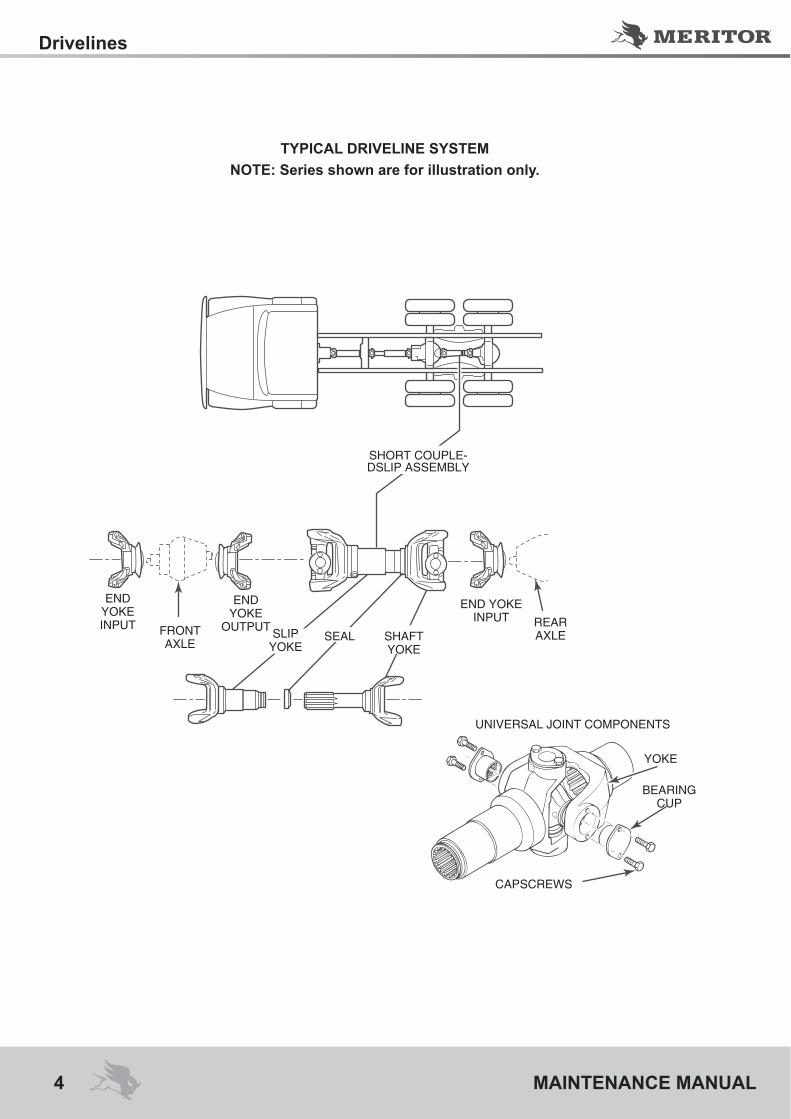
TYPICAL DRIVELINE SYSTEMNOTE: Series shown are for illustration only.
Figure 1.2
SHORT COUPLE-DSLIP ASSEMBLY
END YOKE INPUT FRONT
AXLE
END YOKE
OUTPUT SLIP YOKE
SEAL SHAFT YOKE
END YOKE INPUT REAR
AXLE
UNIVERSAL JOINT COMPONENTS
CAPSCREWS
YOKE
BEARING CUP

5
Introduction
MAINTENANCE MANUAL
DescriptionMeritor Xtended Lube MXL™ 17N, 176N and 18N Series DrivelinesThe Meritor Xtended Lube MXL™ 17N, 176N and 18N Series drivelines have extended lubri-cation intervals for both the slip sections and universal joints at 100,000 miles (160 000 km) for linehaul applications.
How to Identify an Xtended Lube MXL™ Series Driveline• The slip yoke seal includes a protective ste-
el shroud to improve sealing and retain seals securely in place. Figure 2.1.
• The universal joint cover plates are stamped “MXL.” Figure 2.1.
Figure 2.1
Figure 2.3
Meritor Full-Round and Easy Service™ (Greaseable)The Full-Round, Figure 2.2, and Easy Servi-ce™, Figure 2.3, greaseable drivelines require periodic lubrication of the universal joints and slip yoke splines.
Figure 2.2
MX
L
MX
L
MXL STAMP
STEEL SHROUD
Meritor Xtended Lube MXL™ Series
FULL-ROUND
EASY SERVICETM (1/2 ROUND)

Removal and Disassembly
6 MAINTENANCE MANUAL
Hazard Alert MessagesRead and observe all Warning and Caution ha-zard alert messages in this publication. They provide information that can help prevent se-rious personal injury, damage to components, or both.
WARNINGTo prevent serious eye injury, always wear safe eye protection when you perform vehicle maintenance or service. Park the vehicle on a level surface. Block the wheels to prevent the vehicle from moving. Support the vehicle with safety stands. Do not work under a vehicle su-pported only by jacks. Jacks can slip and fall over. Serious personal injury and damage to components can result.
Removal
Driveline1. Park the vehicle on a level surface. Block the
wheels to keep the vehicle from moving. Rai-se the vehicle so that the area you will servi-ce is off the ground. Support the vehicle with safety stands.
2. Loosen and remove the capscrews from the end yoke bearing cups.
3. Remove the first bearing cup. If necessary, use a bearing puller to remove the bearing cup from the yoke bore. Figure 3.1.
Figure 3.1
4. Remove the second bearing cup. Figure 3.2.
Figure 3.2
NOTE: Support the driveline when you remove it from the end yoke.
5. Slide the yoke to one side until you can work a trunnion free from the yoke bore.
6. Slide the yoke in the OPPOSITE direction while removing the universal joint from the end yoke.
7. Repeat Step 2 to Step 6 to separate the slip yoke end of the driveline.
Universal Joint1. Loosen and remove the capscrews from the
two remaining bearing cups on the yoke end of the driveline.
2. Remove the bearing cups. If necessary, use a commercial bearing puller to remove the bearing cups from the yoke bores.
3. Work the trunnions free of the yoke bores. Remove the universal joint cross from the weld yoke.
4. Repeat Step 1 to Step 3 to remove the uni-versal joint cross from the slip yoke.
DisassemblySlip Yoke
WARNINGUse a brass or synthetic mallet for assembly and disassembly procedures. Do not hit steel parts with a steel hammer. Pieces of a part can break off. Serious personal injury and damage to components can result.
4001893a
UNIVERSAL JOINT PULLER TIGER TOOL
NUMBER 10102
BUSHING
4001839a

7
Removal and Disassembly
MAINTENANCE MANUAL
1. Use a brass or copper hammer and a drift to tap the shroud off the slip seal. Be careful not to damage the shroud. Figure 3.3.
Figure 3.3
2. Use a screwdriver to pry the seal out of the groove in the slip yoke. Figure 3.4.
Figure 3.4
3. Mark the slip yoke and slip shaft sections to ensure that you reassemble them into their original positions. Figure 3.5.
Figure 3.5
4. Pull the slip yoke and slip shaft sections apart. Figure 3.6.
Figure 3.6
5. Remove the seal. Figure 3.7. Remove the shroud. Figure 3.8.
Figure 3.7
Figure 3.8
4007587a
MX
L
HAMMER
DRIFT
4007588a
MX
L
4007589a
MX
L
MX
L
MX
L
MX
L
4007590a
MX
L
MX
L
4001823a
4001824a

Assembly and Installation
8 MAINTENANCE MANUAL
Hazard Alert MessagesRead and observe all Warning and Caution ha-zard alert messages in this publication. They provide information that can help prevent se-rious personal injury, damage to components, or both.
WARNINGTo prevent serious eye injury, always wear safe eye protection when you perform vehicle maintenance or service. Park the vehicle on a level surface. Block the wheels to prevent the vehicle from moving. Support the vehicle with safety stands. Do not work under a vehicle su-pported only by jacks. Jacks can slip and fall over. Serious personal injury and damage to components can result.
Assembly
Slip Yoke1. Install the new shroud. Figure 4.1.
Figure 4.1
2. Install the new seal onto the spline shaft neck. Ensure that the seal is installed with the SMALL diameter side facing DOWN for correct installation. Figure 4.2.
Figure 4.2
4. Install the spline shaft into the slip yoke until the splines fully engage. Figure 4.3.
5. Snap the seal into the groove. Figure 4.4.
3. Align the slip yoke and spline shaft sections with the phasing marks you made on these sections during disassembly. Figure 4.3.
Figure 4.3
Figure 4.4
4001828a
4001829a
4007591a
MX
L
MX
L
4007592a
MX
L
PHASING MARKS
SMALL DIAMETER
SHROUD
LARGE DIAMETER

9
Assembly and Installation
MAINTENANCE MANUAL
6. Verify that the seal has been correctly ins-talled on the slip yoke by rotating the seal. When the seal is installed correctly, the seal will rotate easily.
• If the seal does not rotate easily: Remove the seal and reinstall it.
7. Install the steel shroud over the seal by hand. Figure 4.5.
• If it appears that a mallet is needed to install the shroud: It is likely the seal has not been installed correctly.Repeat Step 6.
Figure 4.5
8. Push together the driveline sections. Figure 4.6.
Figure 4.6
InstallationUniversal Joint
WARNINGUse a brass or synthetic mallet for assembly and disassembly procedures. Do not hit steel parts with a steel hammer. Pieces of a part can break off. Serious personal injury and damage to components can result.
1. Install the universal joint cross into the yoke.2. Install the two bearing cups through the yoke
bores and onto the universal joint cross trun-nions. If necessary, use a copper or brass hammer to tap the bearing caps until they are fully seated.
3. Hand-tighten the capscrews through the bea-ring cover plate and into the slip yoke.
4. Use a torque wrench to alternately tighten the capscrews to the correct specifications. Re-fer to Table A.
5. Repeat Step 1 to Step 3 to install the univer-sal joint cross into the weld yoke.
Driveline1. Wipe off the end yoke bearing bores. Insert
the trunnion through the yoke bore.2. Check the bearing cup to ensure that the ne-
edle bearings are in place. Replace the bea-ring cup when the needle bearings are mis-sing or out of place.
3. Hold the cross. Use a copper or brass ham-mer to lightly tap the bearing cup completely into the yoke bore. Figure 4.7.
Figure 4.7
Figure 4.5
4007593a
MX
L
MX
L
MX
L
4007595a
4001840a

Assembly and Installation
10 MAINTENANCE MANUAL
4. Align the cover plate holes and the yoke ear. Figure 4.8. Install the bearing cover plate flush against the milled surface of the yoke.
Figure 4.8
5. Install new capscrews and hand-tighten them through the bearing cover plate and into the yoke.
6. Repeat Step 2 to Step 5 to install the second bearing cup.
• If the cover plate will not seat flush against the yoke surface: Remove each bearing cup from the yoke bore. Check the bottom of each bearing cup. If you find a needle bearing, re-place the bearing cup.
7. Use a torque wrench to alternately tighten the capscrews to correct specifications. Refer to Table A. Figure 4.9.
Figure 4.9
Table A: Torque Specifications — Full--Round
Driveline Series
“A” Inches (mm)
Thread Size
Inches
Torque Specs lb-ft
(Nm)
16N 5.31 (134.87) 5/16-24
26-35(35-47)
17N 6.09 (154.69) 3/8-24
38-48 (51-65)
176N7.00
(177.8)3/8-24
38-48 (51-65)
18N 7.55 (191.77) 3/8-24
38-48 (51-65)
4001841a
4001842a
CAPSCREWS
“A”
4001848a
YOKE GAUGE TOOL
Identifies driveline series
“A” dimension across yoke ears determines end yoke/universal
joint series.

11
Lubrication
MAINTENANCE MANUAL
Hazard Alert Messages.Read and observe all Warning and Caution ha-zard alert messages in this publication. They provide information that can help prevent se-rious personal injury, damage to components, or both.
WARNINGTo prevent serious eye injury, always wear safe eye protection when you perform vehicle maintenance or service. Park the vehicle on a level surface. Block the wheels to prevent the vehicle from moving. Support the vehicle with safety stands. Do not work under a vehicle su-pported only by jacks. Jacks can slip and fall over. Serious personal injury and damage to components can result.
Universal JointAfter installation into the end yokes, lubricate the universal joints at the grease fitting until grease flows from the bearing cup seals on all four trunnions. Use Meritor grease specification O-634-B, NLGI Grade 2 with EP additive. Figu-re 5.1.• If grease does not purge from the seals:
Follow the steps below.
Figure 5.1
1. Move the assembly UP-AND-DOWN or SI-DE-TO-SIDE while you apply grease gun pressure. Figure 5.2.
Figure 5.2
2. Loosen the bearing cup capscrews. Add gre-ase until grease purges from the seals.
• If grease still does not purge from all four trunnion seals: Remove the universal joint and correct the problem.
• If you cannot determine the problem: Repla-ce the universal joint.
3. Tighten the capscrews. Refer to Table A.
Slip Yoke SplinesNOTE: To ensure correct and adequate lubrication of the splines, the slip assembly should be fully collapsed or nearly fully collapsed be-fore applying grease.
Add Meritor specification O-634-B, NLGI Gra-de 2 with EP additive to the slip yoke grease fitting as shown in Figure 5.3.
Figure 5.3
4001843a
New grease mustflow at all four seals.
Shown without end yokes for clarity.
4001844a
4001846a

Lubrication
12 MAINTENANCE MANUAL
The amount of grease will vary with the driveline series. To avoid purging excess grease through the slip yoke welch plug when the assembly is fully collapsed, follow the recommendations in Table B.
* Xtended Lube MXL™ Series drivelines are identifiable from RN drivelines in the following two ways. (1) The slip yoke seal includes a pro-tective steel shroud. (2) The universal joint co-ver plates are stamped with MXL™.Meritor RPL25/20 Series drivelines are perma-nently lubricated. No greasing is required.Table B
Driveline Series Grease Volume Number of
Pumps
17N 0.7 oz (20 grams) 4-6
176N 0.7 oz (20 grams) 4-6
18N 1.1 oz (30 grams) 6-8
For Removal, Installation and Lubrica-tion Procedures for Meritor Easy Servi-ce™ and Full-Round 17N, 176N and 18N Series DrivelinesRefer to Maintenance Manual MM-96147, Dri-velines. To obtain this publication, refer to the Service Notes page on the front inside cover of this manual.
Lubrication Intervals for Meritor Easy Service™ and Full-Round RN Series and Xtended Lube MXL™ Series Drive-lines
Table C: Lubrication Intervals
Application MXL* 17N-18N RN 155N-18N
City 25,000 miles (40 000 km) or 6
months
6,500 miles (10 400 km)
On Highway 100,000 miles (160 000 km)
16,000 miles (25 000 km)
Linehaul 100,000 miles (160 000 km)
50,000 miles (80 000 km)
Construction The greasing interval depends on the individual conditions, speed
and loads. To determine the interval, inspect for the presence of grease at all positions until an
interval can be determined. Grea-se the assembly as necessary.
Table D: Approved Lubricants
Lubricant RecommendationUniversal Joint Grease
Must meet Meritor Specifica-tion O-634-B(NLGI Grade 2, Lithium 12-Hydroxy Stearate with Molybdenum Disulfide)Amalie All Purpose Grease withMoly-L1-2MExxon 5160Shell Super Duty Special FFMarathon Maralube Molycode 529Phillips Petroleum Philube MW-EP2 GreaseShell Moly Poly GreaseKendall L424 GreaseAmoco Super Chassis Gre-aseFord Specification M1C-75B or partnumber PN-C1AZ 19590

MAINTENANCE MANUAL
Always use Technical Manuals of...

Always use original parts
For more details, see the Spare Parts Catalog
Customer service
55 11 3684.674155 11 3684.6867
Purchase the CD-ROM failure analysis of components of the axistraction
Customer ServiceAv. João Batista, 825 - Osasco - SP - 06097-105
Tel. (11) 3684-664 - (11) 3684-6867
AfterMarket (Replace parts)R. Ester Rombenso, 403 - Osasco - SP - 06097-120
Tel. (11) 0800-555530
www.arvinmeritor.com