Embed Size (px)
Citation preview

AD0-A47 049 EVALUATION 0f THE' ORT NOZZLE DESIGN FOR THE UNIlED /SATES COAST GUARD 140 WYTM CUTTER(U) NAVAL ACADEMYANNAPOLIS MD DIV OF ENGINEERING AND WEAPONS T d LANGAN
UNCLASSIFIED 1984 USNA EW-15-84 F/G 13/10 lEiEEEinElimIIhEEEEEEEEEEEEIIIEEEEIIEEIIEEIIEEEEEEEEIII
IIIIIIIIIENS

I 1.0 2 2 _
I I 2 2
~ II'*'lB11111_L25116
k I Fi It )TI N I , 4 I'

UNITED STATES NAVAL ACADEMY
DIVISION OF
ENGINEERING AND WEAPONSI ANNAPOLIS, MARYLAND
NOV 5 1984
I ~uL1;c84 1 0 3 0 1 38Distliul lnhn Uniijted

Pr I- ~ 1Na.ia Sy LInMS Eng;inceoring Do partoont
U. S Naval Ac ademyvAnnapolis , MIaryland
LAccession For
!4TIS G RA IDTIC T~l [3
Ufl~lh~o1tc C Approved for public release;I Justt i c 21 distribution UP I hnlited
Awi -
Di t 11 1

Sii . j-i ijJ. st ril i i ,
I - tr I It - U I .I r I I (\ * I( I~u ic Co I "id ±t I
, m C li't nI3
V .~ w I .I nlt 1 4'
n. (c I rt2neii 1 5
Apped iK . w;z VAnilvs is lb1
Append ix B3: Pr spt-11 or Ma1 de t;e oinet r\
1pe lid ix C: 0r op 1) c II r Is r (, 2,; 37
ApeniDI: St rue Luri I Analvs is () IC he 1 ade U.nder Icc Loading 56
+,~~--

t , no'OLCT L(T'
Tl'is ru.pcrt r.!;ents .in ovaluation of the proposed kort uozzI, Ir tlit I
wY'rI C( tter. [t-con;siders t hu shroud s ructlire, th. propeller hvdrodv iia i, ,
i . u the pr,'oeIttr blade, a posh;ihc ice ,et lct ioli stru ,
overall design of the kort nozzle. Thu shroud structure is considered first in
Section 1, wiiere it is found to be sufficiently strong. - & r-tion 2 goes into
the propellor hydrodynamics, whi le Section 3 considers" the remaining topics.
one urious problem with the present design is that there is no access to
the prope LIr. Unless the port, starboard, or both sides of the nozzle is remo-
vable, the propeller would have to be installed and the shroud built around it.
The screw would be inaccessable for repairs. Suggestions for how this problem
could be solved are put forwardin Section 1.
The thrust and efficiency of the propeller together with the shroud meet
requirements. Hkowever, the local velocity distributions are not hydrodynami-cally the best and result in cavitation on portions of the back and face of the
blades. Slight modifications to the sections should alleviate this situation; a
very efficient subcavitating propeller should result. Details may be found in
Section 2 and Appendix C.
Unless the propeller blades are to be steel, they are not strong enough towithstand extreme ice loading. Details of the ice loading are given in Section
3 and Appendix D. Recommendations 4 and 5 in Section 4 address this problem.
Supports for the nozzle are oi .-o discussed in Se," ion o.. lese should be
faired in to prevent adverse hydrodynamic drag, which reduces the total net
thrust. .
Recommendations may be found in Section 4.
iI
II
I 'Til: SIIROII) STRUCTURK
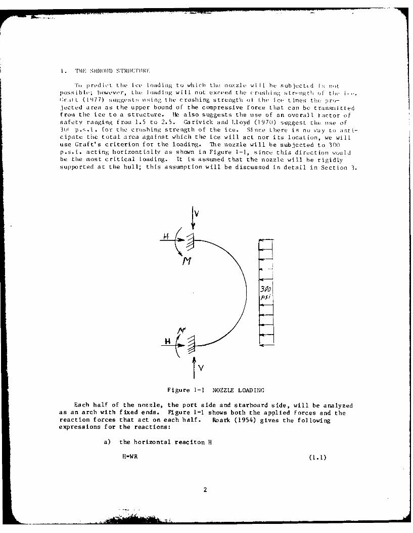
To predict the ice loading to which the nozzle will lie sub ected i!; notpossibl c; however, the loading will not exceed the crushin;; strengthi of th i,,.(t.1i (1477) .suggests usi n;. the crushing strength of the ice t imes the pro-jeced area as the upper bound of the compressive force that can be transr.ittedfrom the ice to a structure. Ile also suggests the use of an overall tactor ofsafety ranging from 1.5 to 2.5. Garivick and Lloyd (1970) suggest the use of30 ( p.s.i. for the croshing strength of the ice. Since there is no vay to anti-cipate the total area against which the ice will act nor its location, we willuse Graft's criterion for the loading. The nozzle will be subjected to 300p.s.i. acting horizontially as shown in Figure 1-1, since: this direction wouldbe the most critical Loading. It is assumed that the nozzle will be rigidlysupported at the hull; this assumption will be discussed in detail in Section 3.
psi
14
V
Figure 1-1 NOZZLE LOADING
Each half of the nozzle, the port side and starboard side, will be analyzedas an arch with fixed ends. Figure 1-1 shows both the applied forces and thereaction forces that act on each half. Roark (1954) gives the followingexpressions for the reactions:
a) the horizontal reaciton H
I1-WR (1.1)
2
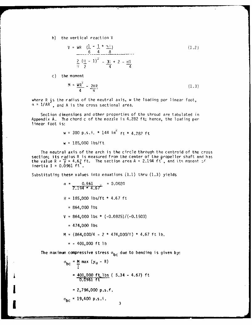
h) the vertical reaction V
V = WR (1- .1 + ) (1.2)6 4 8
2 (1i - 1) - 31 + 2 - all!' 2 4 4
c) the moment
2M = WR - 2HR (1.3)
4 T-
where R is the radius of the neutral axis, w the loading per linear foot,a = I/AR , and A is the cross sectional area.
Section dimensions and other properties of the shroud are tabulated inAppendix A. The chord c of the nozzle is 4.282 ft; hence, the loading perlinear foot is:
2w = 300 p.s.i. * 144 in ft * 4.282 ft
w = 185,000 lbs/ft
The neutral axis of the arch is the circle through the centroid of the crosssection; its radius R is measured from the center of the propeller shaft and hasthe value R = = 4.64 ft. The section area A = 2.194 ft , and its moment 7,finertia I = 0.0961 ft .
Substituting these values into eauations (1.1) thru (1.3) yields
a 0.961 = 0.0020
H = 185,000 lbs/ft * 4.67 ft
= 864,000 lbs
V = 864,000 lbs * (-0.0825)/(-0.1503)
= 474,000 lbs
M = (864,000/4 - 2 * 474,000/11) * 4.67 ft lb.
= - 401,000 ft lb
The maximum compressive stress 0 bc due to bending is given by:
C bc = M max (Yu - R)
= 401 000 ft lbs ( 5.34 - 4.67) ft- . g61 -f- -
j = 2,796,000 p.s.f.
0bc : 19,400 p.s.i. 3
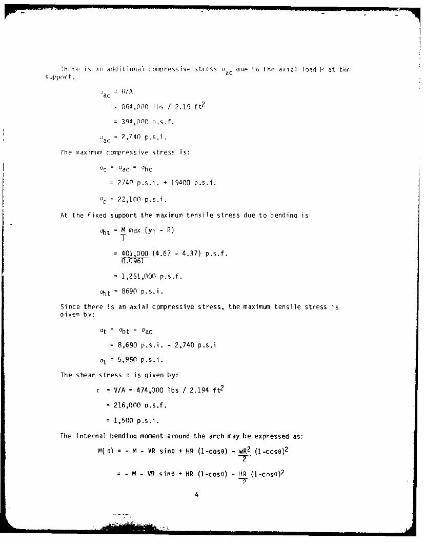
There is mi a ddit ionalI compvress ive strers a ac due to the axial load H1 at thesupport
ac H/A
=864i,000 lbs / 2.19 ft 2
=39)4,OflO n.s.f.
ac = 2,740 p.s.i.
The maximum cornpr,-ssive ;tress is:*
Or = ac ac
= 2740 p.s.i. + 19400 p.s.i.
0= 22,100 p.s.i.
At the fixed support the maximum tensile stress due to bendina is
ot= M max (yj - R)I
= 401,000 (4.67 - 4.37) p.s.f.
= 1,251,000 p.s.f.
uht = 8690 p.s.i.
Since there is an axial compressive stress, the maximum tensile stress isniven by:
at = Obt - Oac
= 8,690 p.s.i. - 2,740 p.s.i
ait =5,950 p*s*i.
The shear stress Tr is qiven by:
T V/A =474,000 lbs / 2.194 ft2
=216,000 p.s.f.
=1,500 p.s.i.
The internal bendinq moment around the arch may be expressed as:
M( e) =-M -VR sine + HR (1-cose) - wR2 (1-cosq)2
-- M -VR sine + HR (1-cose) - HR (1-cnse)2
4

Whprp M pnsitive indicatps inner side (lowor surfacp) in tension.
M' (O) - HP cosO + VR sine - VR(1-cos,) sinu
- HP cosO + VP cos3 sin,
The roots of M' (0) : 0 are b = n and
sino HP = H = 474,000 = 0.5486VR V 864,000
or
0 = 0, 33.27', 71 - 33.27'
The moments at these points have the values
M(O) = 205,000 ft ib
M (33.270) = M (7 - 33.270) = -206,000 ft lb
The level of stress for the arch is small, so that a low carbon steel can beused for its construction. This has the additional advantaqe that low carbonsteels are a tough material with good resistance to impact loadin. Thenozzle will be subjected to impact loadings from ice at low temperature.
With the present nozzle design there is no access to the propeller. Eincethe stress level within the shroud is low, the port -)r both tK, port and star-board sides could be made rem,-able to provide the Iecedry access. Oneapproach would be to make the nozzle a built uD structure with a cross sectionlike Figure 1.2.
0 t) T1 PF PL, C-F
.BEA M
TE tIf rsrDr" PLATE'
Figure 1.2 BUILT UP SFCTION
The structure would consist of a leading edge beam sculotured to the profile ofthe section and a trailina edQe beam also sculptured.
.Inper and lower surfaces between the beams would he made from plates.There would be ribs at approximately 45* intervals. The outer and inner surfaceplates would be made removable. The leading and trailing edge beams would bemade removable near the ship hull and the lower support. One approach to theseconnections would be to have oermenent short beams attached to the hull and thelower support, the leadina edqe and trailinq edqe beams would bolt to thesefixed structures. If this proves impossible, the spacinq between the two beamsmiaht he made larme Pnouqh for the prop to fit through. The removable noz7lP ishowever preferable.I5

2. PPOPFLLFP HYDRODYNAMICS
Fuller (1981b) provided the desiqn criterion for the screw. At a ship speedVs = 6 knots the propeller is to turn at N = 270 rpm at a shaft horsepower SHP =
2400 hp. The wake reduction factor is to he w = 0.177, this relates to a velo-city at r/R = 0.6. The axial velocity into the propeller is then qiven as:
Va = (1-w) Vs = 8.340 ft/sec
Details of the hydrodynamic force calculations may be found in Appendix C.At the above conditions the thrust developed by the screw is aiven in Table C-8as:
T = 33,100 lbs
and the corresponding toraue is:
0 = 45,800 ft lbs.
These values are for a water density p=1.94 lbs. sec2 /ft. At this torquethe delivered horsepower would be:
DHP = 2 If nO = 2,354 Hp550
Where n = 4.5 r.p.s. is the rotational shaft speed.
s = DHP = O.9R1
SHP
Which is right where it should be.
The thrust coefficient for the screw alone is:
KTscrew = T : 0.162,pn2 D4
and the torque coefficient is:
KQ = Q = 0.026pn2 D5
Van Manen and Superiana (1959) determine the thrust constant of the nozle
KTnozzle = 0.110;
consequently, the total thrust constant is:
KT = KTscrew + KTnozzl e = 0.272
The total thrust is:
T = pn 2 r 4 KT = 59,300 lbs,
and the correspondina thrust horsepower THP is:
THP = T Va = P99 Hp
6

Overall efficiency for the screw nozzle combination is:
= THP = 0.382DHP
At 258 rpm for a delivered horsepower, DHP = 2350 Hp, the bollard Dull dueto the propeller is:
Tscrew = 37,400 lbs
The thrust coefficient for the screw is:
KTscrew = 0.199
Addina this to KTnozzle yields a total thrust coefficient
KT = 0.309
for a total thrust
T = 58,129 lbs
This compares with the present bollard Dull of 56,000 lbs at 245 rpm. Theshroud has reducted the bollard pull of the screw by a third without lowerinqthe total bollard pull.
The velocity distribution is obtained throuqh use of the Coldstein (19n2)approximation to Theodoresen's mappinq technique. Veloritv dirtr iutions forr/R = 0.5, 0.7, and 0.9 are shown in Figures 2-1 through 2-3. Details of thismethod can be found in Appendix C. Although the velocity distribution for thesection at r/R = 0.5 at a CL 1 1, figure 2-4, is quite normal; in contrast, atthe desiqn value CL = 0.146 the lower surface velocities exceeds those on theupper surface for the first 15% of the chord. At rR = 0.7 this conditionholds over the first 2.5% and at r/R = 0.9 over the first 10% but not as drasti-cally as at r/R = 0.5. One other bad feature of the velocity distribution isits behavior over the last 25% of the upper surface in the vicinity of r/R =0.7. This erratic behavior is still evident for the same section at CL = 1.
The propeller cavitates under summer operating conditions. Details of thecavitation caluculations are in Appendix C. There is cavitation on the back ofthe blade at r/R = 0.7. There is cavitation along the lower leading edqe froman approximate r/R = 0.5 to the tip. Both of these conditions are due to poorvelocity distribution rather than to an excessive blade loadinq. It should bepossible to operate the propeller cavity free, after minor modifications to thesection shape.
I7.t i7

UPPER SURFACE
0.9 -~/LOWER SURFACE
0.8 -
v/V 0.7
0.5
FIGURE3 1
FIUE2-1 VELOCITY DISTRIBUTION r/R=O.5
1 .4
1 .3 -I %
1.2 UPPER SURFACE \
0.9 'LOWER SURFACE - f
0.7
v/V 0.6
0.5
0.4
0.3
0.2t
0.1
0o-0 123 4
x
FIGURE 2-2 VELOCITY DISTRIBUTION r/R0.7
8I

1.1 -[ -- - - PPER SIJRFACE
0.9i /LOWER SURFACE
0.7j
v/V 0.6
0.5
0.4
0.2-
0.1
0 Iw
FIGURE 2-3 VELOCITY DISTRIBUTION r/R=0.9
|9

i m o ilEIt STRIC RAI. ANI) YIDROlIY:\A.(C U 'AT I ".
St resses due to ice c rushing by the blade are tabu lated i "Lable D--6 i andwere derived in Appendix D. These stresses exceed tLhe desigj n working stress;(.;for both mangalneese bronzer and nickel alumi num bronize scrt-ws recomtm, uded bv0' hr ien ( 19h2). In fact the o;trkess levels would actal lIlv call for a sttcI
screw. ,Some might argue that the crushing stress of ice i s t, a, severe a loadi- .ac
condition. consider the results for r/R = 0.8; the stress 880) p.s.i. represents a chunck of ice being forced against the outboard 11). 2 inches of the,blade. True, the b lock wou d have t o be 4' wide, hut hi i s p Ls ih1e1 . h'n eb lid., L oul I not s tippo rt an ven sma I Ie r h lotk push i4t' or c-a I to it, f .; [,r
at r/R - 0.8 the appropriate I is 7 in , the maximum distance is ().U39 feet or0.463 inches, and using an allow stress of (i50() p.s.i., the maximurn moment wou,be
Mallowed i~5 p.s.i. * 7 in 4 = 97.222 in lb0.468 in
A I inch thick by 10 inch wide piece of ice, acting with a ' inch moment amn,would mearly have to exert 194 p.s.i. to achieve this lcwl 1 of stress.
A strut stretched between the hull and the shroud as shown in Figure 3-1
could be used to deflect ice away from the blades. It would not however protectthe blades f rom ice coning in astern during backing operations. An NACA Ai)18section would be sufficiently strong to withstand ice loading, as the predictedmaximum stress would be 7780 p.s.i., see Appendix I). It is not possible to pre-dict the direction of flow into the strut; a visual study in a water channelwould be advisable to check out the hydrodynamics of t he, -rut ini it- itt-r.Ak-tion with the propeller.
FAIREO2 -Wo
ForL sFEc re71
FOE A ND A T
W'1,LPI/) AND
FIGURE 3-1 ICE DEFLECTION STRUT
10

For hydrodynamic reasons the upper and lower supports for the nozzle shouldhe faired into the -hip hul I. tructtrally they should be made an inteqral partof the hul 1, ,o that i",,v awt a' r iqid supports for the noz7l . Fiqurp 3-2show, ,t [it t hriloh lh upper support (shaded portion) to show the fairinq. Thewidth ot the support should be determined by the location of its lower outside
'9 :~F JLL
3(FA CC-
Figure 3-2 ATHWART SHIP CUT THROUGH UPPER SUPPORT
edge; this edge should be located so that it just provides clearance enough ttremove the propeller. This is approximately the ' 6" buttocks plane. Figure3-3 shows a typical fore and aft section. Two major fe.turec cra the slots into
MOLD TO YILL SkFACE
L, £. F4,7
If ) /M74,p £AL C C otTO RL/5Fr-, PL A .9F4/-
5LOT
Figure 3-3 FORE AND AFT SECTION
which the shroud leadinq edge beam and its trailing edqe beam fit. These beamsshould bolt to the support. It may be useful to have an access plate at midchord to access these bolts; this view shows this plate. Note also that thesupport continues to the rudder support housing and should be faired into thisstructure.
I .....I -IJ1

Ii ,iir. .1-a sthoes v St1 iew of a ,ect ionl t hrough thle l ower sUpport
0Li v rtE
-5~U ORAFAFiue34 OF UI FTO SF.NVE
, ~ F~t12

4. RECOMMENDATIONS
1. The nozzle structure should be made removable to prnvide access to thepropeller.
2. Either the pitch angle, the slope of the mean line, or both should be
adjusted so the sections operate closer to optional CL and the unusually high
velocities on the face near the leading edge are reduced.
3. Section thickness distributions should be investiqated to determine if
they cause the cavitation on the back of the blade. Velocity distributions are
not properly distributed and the section shape needs modification to alleviate
the situation.
4. If the present cutter propellers have not received any significant ice
damaqe, these propellers should be analyzed to determine the maximum stressesthey will support at different r/R values for a safety factor of two. Thesevalues could then be used as ice load desiqn stresses for the propeller underconsideration in this report.
5. Either strengthen the blades to support the loading described inAppendix 0 or design to the stresses described in recommendation 4.
13
5. ACKNOWLFOCFMENTS
I would like to thank Professor Rameswar Bhattachayya, Chairman of theNaval Systems FngineerinQ Department of the United States Naval Academy forintroducinq me to the Burril method and for many hours of technical discussionpertinent to this paper. I would also like to thank Commander Neil J. Collins,Fxecutive Assistant of the same department, for his assistance in expeditinl thepublication of this repnort and for endurino the many other administrativeheadaches that went with its publication.
14 j

6. RFFERFNCFS
Abbott, Ira H. and Albert F von Doenheff (1q49), Theory of Wing Sections, DoverPublications, Inc., New York.
Burril, L. C. (1944), Calculation of marine propeller performance charac-teristics, Transactions N.F.C.I. 195.
Fuller, Nathan R. Jr. (1981a), United States Coast Guard Drawing, Kort Nozzlefor 140 WYTM Cutter.
Fuller, Nathan R. Jr. (1981b), Design notes.
Goldstein, S. (1952), Approximate two-dimensional airfoil theorQy. Parts I-VI,Curr. Pap Aero. Res. Coun. London 128, 140, 141.
Graft, William (1977), Mechanical Properties of sea ice as they influence desiqnconsiderations, Interpipe 77, The fifth International Pipeline TechnologyConvention, Houston, Texas.
Langan, Thomas J. and Henry T. Wang (1974), Evaluation of liftina - surfaceproqrams for computinq the presstre distribution on planor wings in studymotion, Computers and Fluids 2, 53-78.
O'Brien, T. P. (1962), The Design of Marine Screw Propellers, HutchinsonScientific and TechnicaT,London.
Roark, Taymond J. (1954), Formulas for Stress and StraIn, McGrP il iiI BookCompany, Inc..
Thwaites, Bryan (1960), Incompressible Aerodynamics, Oxford at the ClarendonPress, Oxford, England.
Van Manen, J. D. and A. Superian (1959), The design of screw-propellers innozzles, International Shipbuilding Proaress 6, 95-113.
15

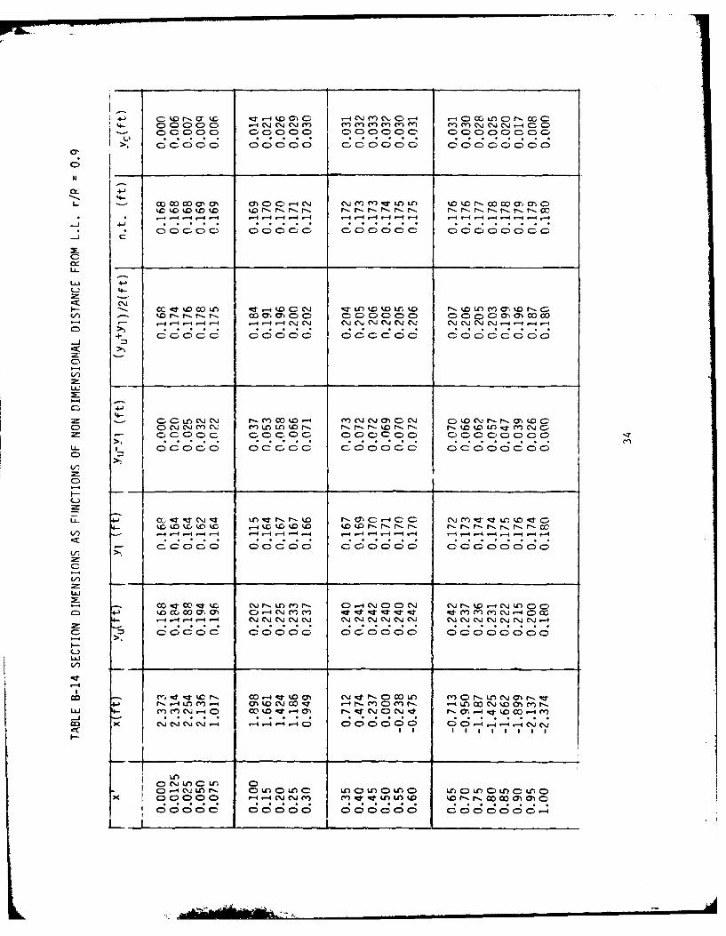
APPEINDIX A NOZZLE ANALYSIS
The shroud dimensions in this report are from the 140 WYTh CutterPropeller Data which are stored on the Naval Academy 'rime Sharing System(NAI'S). This data was digitized from the United States Coast Guard Drawing
(Fuller 1981). The section data presented in Table A-I is good to 0.005 ft,
i.e. t).06 inches. Both y, and Yj are scaled data; whereas, the fore and aft
coordinate X is a direct reading in inches from the drawing. x is the scaledversion of X, where the scale factor '/1.5" is used.
TABLE A-1 SHROUD SECTION
Upper Surface Lower Surface
(in) x(ft) Yu(ft) X(in) x (ft) YI(ft)
3.176 2.117 5.114 3.176 2.117 5.114
3.125 2.083 5.180 3.038 2.025 4.906
3.025 2.017 5.233 2.621 1.747 4.650
2.925 1.530 5.240 2.183 1.455 4.6F1
2.236 1.491 5.150 1.584 1.056 4.371
-0.022 -0.015 4.918 0.774 0.516 4.314
-0.022 -0.015 4.925 -0.106 -0.070 4.316
-0.092 -0.061 4.898 -1.536 -1.024 4.330
-1.790 -1.193 4.730 -2.586 -1.724 4.372
-3.118 -2.125 4.590 -3.106 -2.701 4.402
-3.228 -2.152 4.549 -3.207 -2.138 4.436
-3.247 -2.165 4.482 -3.247 -2.165 4.482
16
-3 : ." __'- . , .
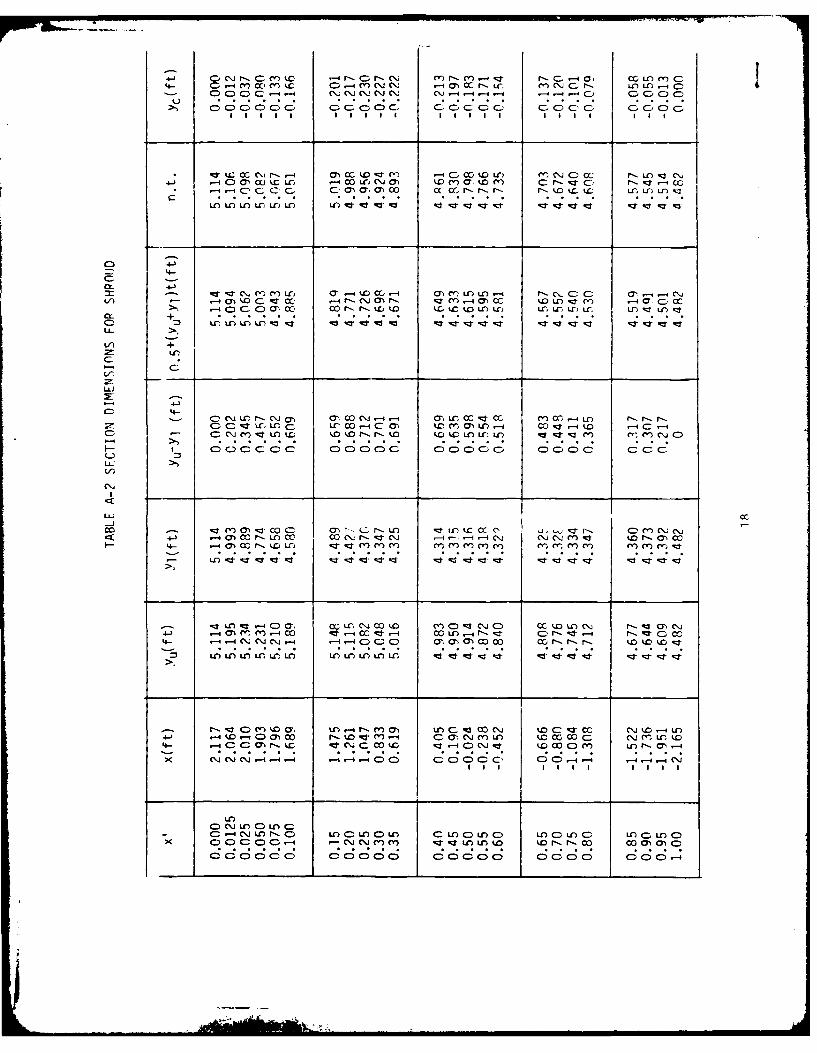
TABLE A-2 presents this section data as a function of the nondimensionaldistance
x = (xLF - x)/c
where xLF is the x-coordinate of the leading edge. From the table xLF = 2.117
ft; c is the section chord length and is qiven as
c = xLE - XTE
T.E. denotes trailina edge; from the table XTE = -2.165 ft. Hence,
c = 2.117 - (-2.165) = 4.282 ft.
In the table n.t. denotes nose to tail line, i.e. the line hetween the leadingedge and the trailinq edqe. Yc is the camber line approximation:
Yc = 0.5 (YU + Yl) - n.t.
The upper surface coordinate Yu and lower surface coordinate Yl are linearinterpulations of the data in Table A-i. The maximum thickness of the shroud is0.712 ft from the tabulated values of Yu-Yi, and this mimimum thickness occursat 25% of the chord. Maximum camber also occurs at 25% of the chord and has theabsolute value 0.230 ft.
17
C, Cej r, C m D. -4 r- C-r- C\, I~r ce) n- r- e-- -- 4 C Lu-r ) C)S C .-4 m~ cc mC C) .- 4 Y a r j .- 1 () CC r-. ur mn C C. r ulC V) -4 C
C) C C) C C\; ci )Cccj C \; c.C 4 14 - 1 CCC)c GC.oC> CD
40 C \ erjr-4- m c10 -4 00tD in (\C)c CC fl ) 0 ~*~~~~C -i,-ic C. COaO C--N-''
O LO .n .r .r LO . .0 n; ;
4-
q*- q* '- cn m~ U-) 0,- 4 t.0CLa -4 01 (n Ln Lfl) -- I f- C\. C C 0'.,- C\j
V)mW c*o. I) C\, M 'Ceqzr L-4 D) :T C .- 4 ac.i
L/',
LJ.J
-4-c1 C .-a O r- Cl 01 C C' i -r31 Lr (\J ,4- -- ccj enJ 0\J -) 'CN r- a)
o - 4 -;t LQ) 'C .j 00 "- C) C0) (') M )CC) 4 CO C.0 -4) c' -I)C
- C\! 0- a)C).J)' Clc c\ L9L)C. r- 9ll ' rl 9 k k 0'~ C . ! Ci C . C.-- I C C.D C'. C'J C) C 4.- C) C) C 0.C 0 C, a) C) C C> 'C C r-C
Lt)UCJuC)r
-C\,J~-0 L C)~L) C CCL 0 u~)CC COCC
0 0k0 0 0 0 I0 0 0 00 0 -

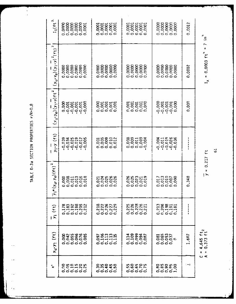
Section propertie? for the shroud are calculated by dividing the shroud sec-
tion into elements Ax =O.O5 units wide, as shown in Figure A-i.
c_-p
Figure A-i DIVISION OF SHROUD
Since yu-Yl=O at both the leading and trailing edges, the section's total area A
in terms of the trapazoidal rule is:
A = 0.05c Z (Yu-Yl)
By definition and the trapazoidal rule the location 7 of the section centroidfrom the axis of the propeller shaft is:
7= 0.0 5c 'yi (Yu-Yl )i/A,
where i=(yu+yl)/ 2 . Since the centroid of each element is not located at thesame distance from the propeller axis as the centroid of the section but isadditional 7i-7 away, it is useful to use the parallel axis theorem. When thisis done, the moment of inertia I around the centroidal axis for the shroud sec-tion is given by:
T = O.05c (yu-Yl)(-yi_)Z+jTi
where T i = (yu-yl) 3/12.
19

n C. C' 00 cc)- - r- u, C, C') 00O ~ .C w~ Lr GO m- r_~ - LI)
4- C) C)-4C\J C~j M C'j C~j OQC -A -4 C C d C C- C C) cr
- C) CD C)CC C) CC- C CC C-C- CC . C-C) C- C-C. C- C
4--
0>. -4l 5-4- r C) -4-4CjcnC MCI> C - -N \j C- 0C CD--4 (Y) * '.0rl r - r c O~.C) C'.
a CLo C\j - C C CD-C- C-CD-C C- C-C-C- C C)-C-C -- C: Lo CC-CC-C- C-C-CC C -: = CC- C- C- C-)cC CC -4
- .: . . C-> D CC-- CC- C CC-CC C- CCCC C C CC C
4-)4-
LL
C: 4- -qr - Ct 0-4 kD r- C'OLC, f) 0' -T 00 4 -4 C'jC-C - Im -Kt Cl) - *C Ll Cj cC'j M Ul P'..OCCD-4 M '*' -) rO o- ICL *'C% M-4 -AC )C)CC)-0CC- ) - -4 -4-4 .- 4 - r"--4 -4I> . . . .
I cC-CC4= C C)'C C C C: C CC C-'. C) - 7-Z
C- co r- - ot ' -I I~ ko IC C) M' Io LO M r, I- I>j 4-' ~ - ~ ~ - )rl L ~ ) O t ~ lC
-4-
>5C CCr- a)' cC'- C)U'0.C C') a c LCC) .. C-
I;\;
C- )cC c0 C)c C CCC C C- C- C)-C C C C- C-C
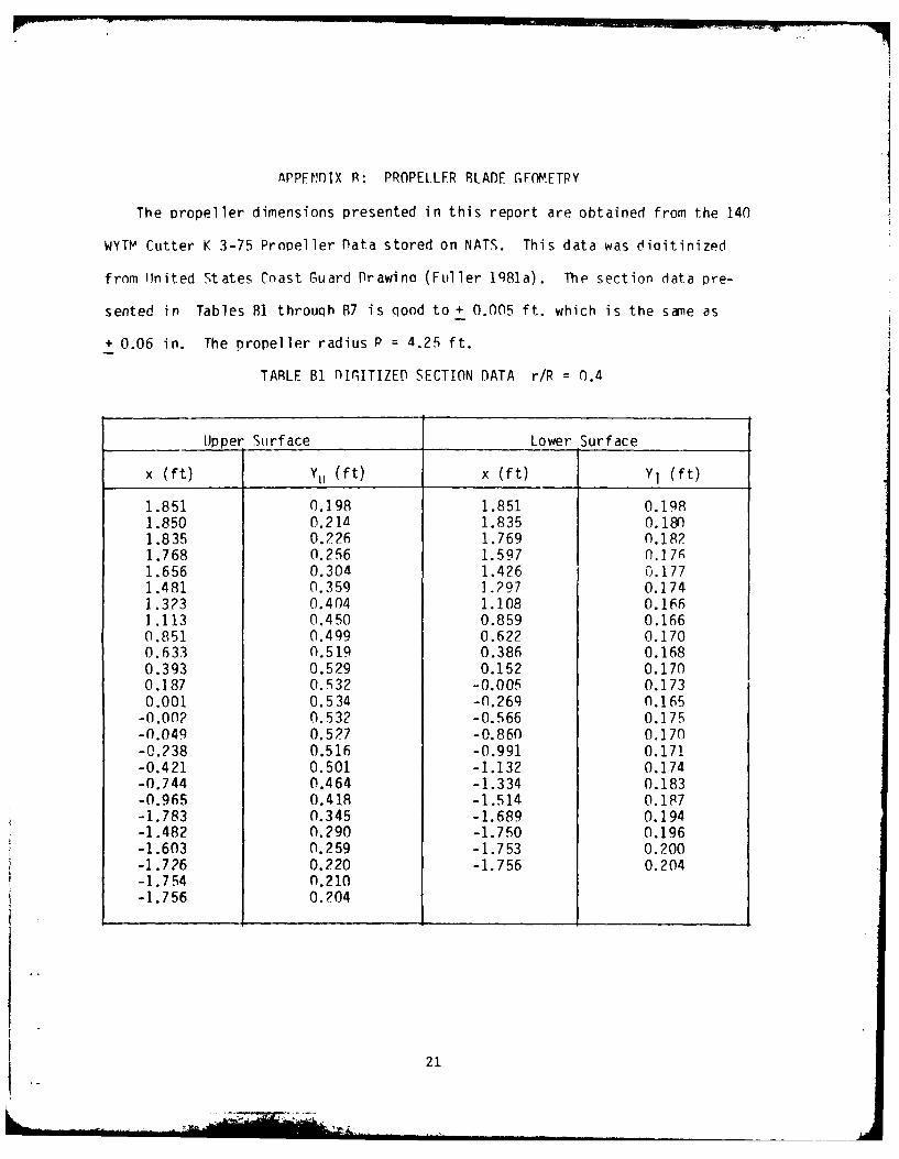
APPEjfIX R: PROPELLER RLADE GEOMETRY
The propeller dimensions presented in this report are obtained from the 140
WYTM Cutter K 3-75 Propeller Data stored on NATS. This data was diqitinized
from United States Coast Guard Drawino (Fuller 1981a). The section data pre-
sented in Tables B1 throuqh R7 is qood to + 0.005 ft. which is the sane as
+ 0.06 in. The propeller radius P = 4.25 ft.
TARLE B1 nIGITIZED SECTION DATA r/R = n.4
Upper Surface Lower Surface
x (ft) Yu (ft) x (ft) YI (ft)
1.851 0.198 1.851 0.1981.850 0.214 1.835 O.18n1.835 0.226 1.769 0.1821.768 0.256 1.597 0.17A1.656 0.304 1.426 0.1771.481 0.359 1.297 0.1741.3?3 0.404 1.108 0.1661.113 0.450 0.859 0.1660.851 0.499 0.622 0.1700.633 0.519 0.386 0.1680.393 0.529 0.152 0.1700.187 0.532 -0.005 0.1730.001 0.534 -0.269 0.165
-0.00? 0.532 -0.566 0.175-0.049 0.527 -0.860 0.170-0.238 0.516 -0.991 0.171-0.421 0.501 -1.132 0.174-0.744 0.464 -1.334 0.183-0.965 0.418 -1.514 0.1P7-1.783 0.345 -1.689 0.194-1.482 0.290 -1.750 0.196-1.603 0.259 -1.753 0.200-1.726 0.220 -1.756 0.204-1.754 0.210-1.756 0.?04
21

TABLE B-2 DIGITIZED SECTION DATA r/R = 0.5
Upper Surface Lower Surface
x (ft) Yu (ft) x (ft) Y (ft)
1.988 0.193 1.988 0.1931.982 0.199 1.984 0.175
1.972 0.209 1.966 0.1671.913 0.223 1.932 0.1651.788 0.258 1.831 0.1621.621 0.295 1.686 0.1611.441 0.332 1.448 0.1651.196 0.381 1.248 0.1650.892 0.424 1.047 0.1660.631 0.449 0.686 0.1650.393 0.461 0.162 0.1690.299 0.464 0.001 0.167
-0.004 0.468 -1.181 0.170-0.082 0.467 -O.A08 0.166-0.318 0.457 -0.638 0.172-0.522 0.443 -0.911 0.176-0.739 0.430 -1.207 0.174-1.027 0.397 -1.396 0.172-1.225 0.369 -1.618 0.172-1.434 0.319 -1.81O 0 !is-1.702 0.260 -1.935 0.182-1.838 0.223 -1.941 0.182-1.915 0.206-1.937 0.196-1.941
22
• _ II" . ... ' - -- " All

TABLE B-3 DIGITIZED SECTION DATA r/R = 0.6
Upper Surface Lower Surface
x (ft) Yu (f t) x (ft) Y1 (ft)
1.990 0.191 1.990 0.1911.980 0.205 1.978 0.1751.946 0.217 1.938 0.1651.823 0.246 1.852 0.1601.701 0.266 1.722 0.1611.556 0.289 1.485 0.1591.217 0.328 1.265 0.1610.688 0.378 0.956 0.1670.372 0.396 0.612 0.1660.001 0.40 1 0.222 0.1650.001 0.399 -0.001 0.167-0.134 0.402 -0.241 0.167-0.416 0.392 -0.620 0.172-0.616 0.386 -0.983 0.172-0.807 0.370 -1.322 0.173-1.037 0.354 -1.630 0.172-1.315 0.322 -1.892 0.170-1.490 0.300 -2.052 0.171-1.712 0.266 -2.098 ro. 173-1.855 0.245 -2.10P 0.180-2.002 0.214-2.072 0.201-2.100 0.193-2.108 0.10
1.1.L
[ 2

TARLE B-4 DIGITIZED SECTInN DATA r/R 0.7
Upper Surface Lower Surface
x (f t) Ytu (f t) x (f t) Y1 (ft)
2.242 0.181 2.242 0.1812.238 0.191 2.240 0.1692.196 0.195 2.228 0.1631.982 0.222 2.150 0.1621.766 0.242 2.023 0.1631.494 0.274 1.872 0.1660.971 0.314 1.678 0.1630.467 0.330 1.404 0.1640.001 0.333 1.158 0.166-0.001 0.334 0.640 0.168-0.404 0.331 0.309 0.170-0.680 0.325 0.116 0.168-0.952 0.315 -0.092 0.173-1.174 0.301 -0.382 0.170-1.478 0.276 -0.707 0.178-1.659 0.261 -0.989 0.175-1.804 0.248 -1.326 0.175-2.052 0.215 -1.570 0.171-2.167 0.202 -1.850 0.173-2.227 0.192 -2.046 P.171-2.233 0.184 -2.179 0.174
-2.227 0.178-2.233 0.184
24-im --
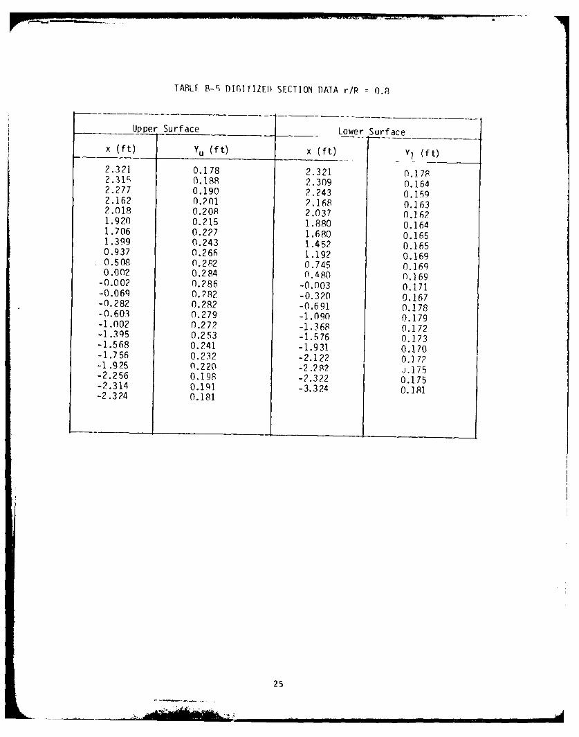
TABLF B-) DIGITIZED SECTION DATA rip = 0.8
Upper Surface Lower Surface
x (ft) Yu (ft) x (ft) Vl (ft)
2.321 0.178 2.321 0.17P2.315 0.188 2.309 0.1642.277 0.190 2.243 0.1592.162 0.201 2.16P 0.1632.018 0.208 2.037 0.1621.920 0.215 1.880 0.1641.706 0.227 1.680 0.1651.399 0.243 1.452 0.1650.937 0.266 1.192 0.1690.508 0.282 0.745 0.1690.002 0.284 0.480 0.169
-0.002 0.286 -0.003 0.171-0.069 0.?82 -0.320 0.167-0.282 0.282 -0.691 0.178-0.603 0.279 -1.OO 0.179-1.002 0.272 -1.368 0.172-1.395 0.253 -1.576 0.173-1.568 0.241 -1.931 0.170-1.756 0.232 -2.122 0.172-1.925 0.220 -2.282 .. 175-2.256 0.198 -2.322 0.175-2.314 0.191 -3.324 0. 1 Al-2.324 0.181
25

TABLE S-6 DfIITIZED SECTION DATA r/R 0.9
Upper Surface Lower Surface
x (f)YU (ft) x (f t) Y I ft)
2.373 0.168 2.373 0.1682.372 0.172 2.372 0.1642.355 0.180 2.315 0.164
2.287 0.186 2.134 0.1622.168 0.195 1.938 0.1652.065 0.194 1.638 0.164
1.910 0.201 1.359 0.1681.736 0.214 0.815 0.1661.536 0.222 0.329 0.170
1.190 0.233 -0.003 0.1710.756 0.240 -0.396 0.1700.407 0.241 -1.161 0.1740.004 0.244 -1.886 0.176
-0.002 0.238 -2.193 0.174-0.570 0.243 -2.308 0.175-1.312 0.235 -2.368 0.172-1.637 0.223 -2.374 .1980-1.830 0.219-2.163 0.198-2.296 0.193-2.372 0.186-2.374 0.180
26

TABLE B-7 DIGITIZED SECTION DATA r/R = 1.0
Upper Surface Lower Surface
x (ft) Yu (f t) x (ft) Y1 (ft)
2.388 0.172 2.388 0.1722.382 0.178 2.386 0.1602.353 0.182 2.376 0.1602.228 0.191 2.337 0.1662.061 0.196 2.259 0.1611.918 0.199 2.166 0.1671.526 0.214 2.035 0.1641.202 0.217 1.829 0.1640.682 0.223 1.287 0.164-0.002 0.224 0.786 0.168-0.002 0.227 0.208 0.169-0.129 0.229 0.001 0.169-0.373 0.223 -0.511 0.171-0.588 0.227 -1.074 0.177-0.826 0.227 -1.524 0.173-1.177 0.220 -2.007 0.177-1.586 0.213 -2.177 0.174-1.826 0.203 -2.300 0.171-1.979 0.202 -2.376 0.170-2.163 0.194 -2.380 n.173-2.300 0.193-2.374 0.186-2.380 0.178
27
4: i . . . . ... ; , , , . .
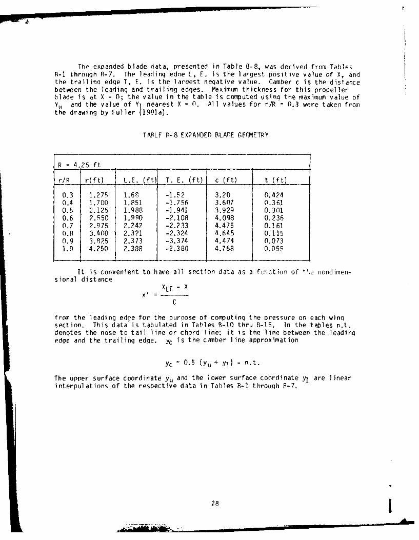
The expanded blade data, presented in Table B-8, was derived from TablesB-I through R-7. The leading edne L, E. is the largest positive value of X, andthe trailina edge T, E. is the laraest neqative value. Camber c is the distancebetween the leading and trailing edges. Maximiin thickness for this propellerblade is at X = 0; the value in the table is computed using the maximum value ofYU and the value of Yl nearest X = 0. All values for r/R 0.3 were taken fromthe drawing by Fuller (1981a).
TARLE P-8 EXPANDED BLADE GFOMETRY
R = 4.25 ft
r/R r(ft) L.E. (ft) T. E. (ft) c (ft) t (ft)
0.3 1.275 1.6R -1.52 3.20 0.4240.4 1.700 1,851 -1.756 3.607 0.3610.5 2.125 1.988 -1.941 3.929 0.3010.6 2.550 1.990 -2.108 4.098 0.2360.7 2.975 2.242 -2.233 4.475 0.1610.8 3.400 2.321 -2.324 4.645 0.1150.9 3.825 2.373 -3.374 4.474 0.0731.0 4.250 2.388 -2.380 4.768 0.055
It is convenient to have all section data as a f:riLion of +',e nondimen-sional distance
XLE - X
C
from the leading edoe for the purpose of computinq the pressure on each winqsection. This data is tabulated in Tables 9-10 thru B-15. In the tables n.t.denotes the nose to tail line or chord line, it is the line between the leadingedge and the trailing edge. Yc is the camber line approximation
Yc = 0.5 (yu + YI) - n.t.
The upper surface coordinate Yu and the lower surface coordinate yl are linearinterpulations of the respective data in Tables B-I through P-7.
28

C> C)00000) ) 4 0)000 C)00 CC 0C)C)
C
00coc 4-o 0OC* , 0) C)0 C) 0000 0000 -4- O ~ ~ ~ ca-
C\!-44 .-- CC% C,% CC\!CJ C\ C\: C\j CJ(%.~l C* C\ C,c
C) ) aC--CO ) Cooo C)C00 lcCC Co C 0000 C
-J3
LL
a~.-. (' C\J LLr to 0. .- I ('U M -r -ca- U) L . j- m' m (\.! C) 00 r-. ::(' CL/) 0-iC C.J C\j C\j C\j )M M~ M' mCr' ell) m)'C)~ m' C' C') C\. M'U (U C~'\j
;7 -1. . C\000 00C C CCi 0CC 000+--J )C )c C C .C ;C C :C = C :C
>)
. C LOr -4 U,) enr 0-. 0 4(otr . O : " C4- 4 -CC2 ) Ct) -- 4Lflr-m - C l)rCC. mciC~ 11 - -4.C~ (= CC rC)CD CD 00 C-D -c -cd c C:U C) c') (' C C') f' C C C C C\. (. C'U .i -4CC
2f
*- -4r4 4-4 -1 -4 -- -4 -4 . -4 r-4 -4 1- -4 .- 4 - - -4-4--1 -4 -. 4 ('U
- 0. 0 C 0 0. 00 C .0 C . . . . .CC . . . .
00 r (x r0 , -, r- f 4 o- c-4 -- C\U C) MC'j -4C.j 1.0 - t CW. --~ MM -t d r 0L0'.)f 0Lr(' C\Jrl C f.-n mtV :r -9- .
. . . . .. .. . . C- 000D C
cc-4k- r- 00CC 0000 0 003 c, 00 0000 tq ll , C r o
c x -4 .-- 44--4 r-4.-400 000C00 cccC C C C-
I * I
C-C\,,LCr-.0 C LflC(-LfO C) c L )LC.C LrlC LCC- X LC:LC C
C* 0c:c-,c- C C COOC 000 000 c 000.-i cC: ( 6

C;
ff e -) Mmm nM c 00 -n\J mOO 0- e\j (1-1 cJ .- I 0i Ca, 'Ol- CC~
4 -
W1CC.. CJ *~ r- c)'c~ cck(\0JC\; 't\J\ C.) z rCen(C\J\
V) -C 4 C 4 -4 -4j Mt -, - 000) -4 4 -4 -q -4 C4 -4) -) -4 -4; (1 -~ 0
-1
c) U' D0 4m -C~ kC' r.c a c *_L) ) C -'--- 1%0 - -- C:
- -C C-4 C-4.- C\J C:. C\J C\J C; CJ C C C: C,) C') ej C C). C-- C'J CDj C-
Z:
V, 4- 0000- 4 4- - -4- - - 4r4- -4 -C\C..CJ\ -4\~VC N -4 r-4 -4 r- -
CCLL;C ;C C C; 0000 C).C0 00CC C; -0 0000 C
L-;X.
cn 0 C) - 4 C ' LC) L-Cf)40 4CD L) to %a 4r- iD Ln 0-1 IC r (1) C7J RT m
-4-4-C%4-! 4 -4 -4 - 7 -4440:q q l q:l q V 13 o -i -4-4- C% -4 -!. -- -
LUJ
CO O 0) oC' mJ(r) c) ~ ~C) C) -4 - S % -t. ICt LerJ r-. LC) - q1--,
LUn
C) CJC') C U*) Cr O ~ ~ ~ 'C\OIA ~ f
C 0 C c) c. ) C '. . . .f 1 4j a:00 U 0 L C! L C! k90 L ~ t9 '0VL tO 1
C) 0000C00 . )C C )0 C C )C ) DC )C) C )C

C) C A C-- LAC~ M ;: LO r- C OD a) a) 0., m '0) a). co r- kD L . .j C~iCo=.(=C, C) CCo C) C-)C--C C C) C_-C)C C C C CC C CC
>. c c; C.. ;C c : cz oCcoo C:( DoDa ; CoooC3C ;C
-4. -4 -4 c C-- c C cn a, 0r- N.k t rlc zrr'm r C'. Cj -4.--4 ('
-- 4-4-:.- -- 4-4- -! 4: -i -i -i-i- -4 - 4 - -- - 4 -4I 7
C)C)CoCoC) C C C--Cl)C) C C) C-0C CDOC. C --C) C CC)
LL-
4-
- - -- 4 4Ci C\ J %0. tZ ~ LC, M". ('O C\0 c0'4 n o o (\C, ('4 m' r_- (Nj, kc' -4 M(N
a, mOC-4.C COCV)-z C0 - co oc co00c ,k o '-m0 C'C) 00-I *~j C... ~ ~ ~ CjCl cCjCj NIciCOCj C~ ~ CC
C'-
S - CD -:rc'J cZic LC MLALA in'.04O~ C: N%,C a -C\. c 0 O C)C' C LA k 1.O C C'J a '.o0 C ) C j m~ m' (' n c') , C%.2 C-) I'r. -, (CN '. , o C
cJ C> 0C0 C1C)0CD C C OC:0C'OCcC) C) CC' C'C CC
C'
V)1 -4-4-4- -4 44- -4 -4 -4 -- 4-4 -4-4 -4 -4 1-4-4 -4-4 -4-4
I,)
-- 4 M -i 4 MN M) LA C' mN (j 1-14 .0 t- 0) M . i -4 -1LA 0., LA C 0 u C)
im 4J cr. 0 000noto 000 orC 00 )c0)00 00 -O-CCOOCm 0
-4
1c, 0 o *)m -Lo4.ko4.w 1- t c-.4- 0 00 0000rO -4...o4.-40('40
I-j
U*)C0 '.ju)LO 0
C)- H )r, CL -*4NC Jr' C ) V) CD Ul.0CD.O C lC .)0L0000 0C00 C)00004- jm n o l L Q0 l 00 00 0m0C)

9 !C 9 :U . .
> 00 00 00 00 00 c u Mc,00 00 0MM c o ww
II
Li-
L) 4
c.'J
Z- C a 4 Ln-. M-4 % ) ~ U')--I(n () 0 w-4O0, C
C0 C m t r. r D .je ; - .. c %. DL f.
C)
0 Cr'~~~Lg MLO L.0m cr%ce r-,C'rLl r o~-41 00 aN 00 M C4 'r1 kD -n Lo- - . ~ r - 4 m m
V) 0 000 tc0, ooo oc kc% t c .i(Dk k o oo o r- - t-
-
4J C 000004Cj W t 0000 0c0000Y0mmm I 4 Cc%-e % 00 0
LU-
.--q.-~ C~ 4~0cC ~ \
03 - 0000D 0 0000 0 00 r00 n r 000*00000j% a
LU)(AC ___ __ __ __)____OC_
cC\,U)r ,'rC ni 0i. )')c L)C Lc U)4 --4)c 4r4CjCjC) m c q C nI DI-f-M M ma
C;L 6 C C: 40C C cs C; 6 '6~'j0'~ (~ L - C;

- (-- OCC C C CC C C) 4CC %C() t *qCC* dRC) CCC) 0 C C O )C> CDC CC- )C C: aCC C-C
cc C ; C :C ;C ; C ;C ;C : c
C;
II
-J
C_ N- - c CD C> o -o D C C) C-- C C(' CD C' c c C, CV C: C.00 CC
CCC = . . . . . .
+L C-c CC.C CD C C:C)Cl OCCO -C C) C c;C C C CC;
2:
U- r C ) CC C-)a -CC C CC C_-CcCD CCCC--aCCD
LLCCC 4 C) C C ) N- O-- _-~ 0- C :I CC -- CDC, c-N C C) a CC
-.- 4 en -4 -4' M 444-- -4 mrM D O L -4- W4 -4C)f U--) -. -4-4M
- C% % ! C19I! !aCk CCCC CCC C% o:tC CCC C C
LU~-~ ~~~C C\,0~- LO- (' cC C
C- OCCO6C C C-CCC CC; CC C; CC- C-CC; C-CC
c- ocoo;;c; c c; oc c c r-o co c=,c, Coo C) DC.)C DC
44.-
Ik O kotot toC tD N- N- N- I- Nl N- - N- V- N- fN- Nl- N- -1 N-, - N- 0
C
V) . r.N-- v -, C Cro. m C0 C0C)C00000) )C)RC)a 0000) 00O0-. --4 . ~ .- 4 4 .- 4 -4 C\ C~J ' 0J C\j C j (. C\. C~'j e~j C'~ ~j .- I
M .l % 1 . . . . . .
C- C
'4-21 - .0 C'j r- m 0 -4 n i jCh0 C)C\J ~CN-N- m o c
C) C)Coo m 0, MU' L~ON-D-N-N-I.O-- UDN r - c oV):- - mC
I
u-
C-
V)LU-
M-4c *%l CjfL Mr )r- ~ )C Cjrk 4CjU :
N--4fo- MCJO 00.,0 )- -) -4 Czt.1I0Czr - -* 4-m le m ?~ C -cC% C\4 0 C" C" % '1!C!C%JC"!C% N0 '-4Oo!C" CI!CC.-4r
C- C'.J- C DC DI C )C-C C-4-4.-4(-- C) 0000 c) CD 0 c)%J
CrI I I I ILn
.CT1

4- ~ c ') ~~ccz or_ a)m ococ C) fCjCl ~
It-
S- C\, r-. t-i (14 r-i CV) m- m- r .i Lr) r In kD % kr- r- r- i-~ r*-. r-. oo o
c
Lu ZC-)
CJInL)LC4 Ci.C.I ~ ~ ' ~ fc
- - C-4-4-4-4-4 -4-4-4-- ',M, toL r- 00%-:t *-co4 ' C4-.- .- kc 4
+: 0C.CDC- C(-C C'C C.000 C CD000000 =
CD
U.. U- 00m 0 r-, 00.0h 0)c~0 a) ) o k M k00n00
C?, 4- - 44-4 -4 -4 -44-4 -4 -- -4 4 ---- 4---:r - .. .0.0 .000 0. .000. . 0. . 00..0..0
V)C Dc0 - _ - )C). : C ,C-C C -
Lu~
- 0 qz~r () r- O Lr- CD ~ - o r oLC r- to M In4- C co 00 01 CJ)C 4 4C\j m C\j cjcC IQ C' .J('.-4C r Yjr
t - - - - .-4 CJ! C'. c'. C%. C"! CJ C\!J ("! C% C\! C% Jl C C"! CJ C' \! 4-
U-
4-) 0 J IN to CC J M - -4 4.4 0.000, ) -4 00 CDc)r "V)o 00-i 4 tc r-- '.0
Ix m U-) L( C0 LC) (-0 nC LM C ' - r r )C00000 -1- !C!" 1 q L!L k 9r, " C 09 a 0!CC cc 0C) C 0JLCU) ~O0 a ) 0 C 0u C) a

The propeller pitch for the 140 WYTM Cutter Screw is a modification of the
K 3-75 pitch. This modification was made to accomodate additional thicknessfor added strength in the ice fields: the following table compares the pitches P
and pitch anqles Q for the tw blades. This data was digitized off the UnitedStates Coast Guard Drawing (Fuller 1981 a).
TARLE B-15 PITCH AND PITCH ANGLES
r/R P~t)stndad 375140 WYTM Cte
0.3 . 0.4 q 4.79 2.6 .2821 15 70.4 4.40 0.4119 22.38 2.89 0.27o10.5 4.92 0.36,95 20.23 3.83 ().64 14.8106 5.51 0.3439 18.9 4.5 0.2696 15.07 5.95 0. 31 R3 1766 5.90.26961.50.19 6.38 0.2986 16.63 .2?1 0.2777 15.230.9 7.21 0.300 16.70 7.25 0.3 17 1 .791.0 8.36 0.3131 17.38 8.44 0.3176
36
I IIlll I . .. . .... lI
.. . . . . I

APPENDIX C: PROPELLER FORCES
The approximate solution for the angle of zero lift qiven by the Pankhurstformula (abbott 1959)
ao = 2/C A yc
is used to obtain the theoretical zero lift angle. The values of A are tabu-lated in Table C-1, while those of aO are tabulated in Table C-2.
TABLE C-1 PANKHURST CONSTANTS
X A
0.000 1.450.025 2.110.050 1.560.1 2.410.2 2.940.3 2.880.4 3.130.5 3.670.6 4.690.7 6.720.8 11.750.9 21.720.95 99.851.00 -104.90
Burril (1944) presents a correction factor K. with which to correct thetheoretical zero lift angle to the one found experiMentally. The correctedangle ao actual is also tabulated in Table C-2. Thickness t and chord are fromTable B-8; whereas, the percent of chord at which maximum camber occurs is takenfrom Tables B-9 through B-15. The factor Kao is taken from Burris (1944).
3IIII
| 37

aLn cn m Lfl Cl -c Lrt
m m (\ .- C)
:C) C (71 a, o C) ad a: C9 CO (CO a. a:
) c) C) C) C) C, C
C C, C C C> -
I.) C) r. IC) .. LC - LO
Q- C4 C) ) Cl) c)I C)
c)' C! C) C C )C
4Nj %C4 -4 LC, C cc
IC) C) C' C0.4 r- fC) C) CU - . ) C
C)j
a) C) ) Cr C0 Cl) Cl)
u- -m Cc i r- l. 0 - - a.r-_ Co j .- 4 .- 4 C C ) -
m- IA n C CD a, c'n1:9 C') C) 0) 1 - :.
C) - . m~ a: i-tt q*-.
- ~ 1 0) C) 14: 10 !*- r-L) C') -z) -91
CD0 C C) C; C' -

IThe ship speed V. = f knots, the R['-I = ,= 270 rlin, and the wake reduction
factor W = 0.177 ' an r/R = 0.6, and the shaft horsepower SHP = 2500 hp are fromUnited States Coast Guard notes (Fuller 1981b). With the usual design processeach blade section would have seen an axial velocity Va, where:
V.= (I - W) Vs
= 0.323 * 6 kts
- 4.938 kts
V = 8.340 ft/sec
However, as discussed in the body of the text this axial velocity is multipliedby a factor Vax/Va to account for the experimentally determined velocity profilein the nozzle at the location of the screw ( Van Manen 1962). From Appendix Athe nozzle chord length = 4.282 ft. and the screw diameter D is 8.50 feet.The values of Vax/Va in Table C-3 are for a I/D ratio of 0.50 and were obtained
from Van Manen 1962. The rotational velocity Vrot is given by
Vrot = 2 r n
where n = 270 rpm/60 sec/min = 4.5 rps. The velocity V is the incident velocity
that the blade section sees;
V = (Vax 2 + Vrot2)/2
it comes at the blade from an angi - where
= arc tan (Vax/Vrot)
IIIII1 39

TARLF C-3 INCIDENT VELOCITIES AND RES1ILTANT ANGLF l
rlR Vax/Va(ft/sec ) Vax(ft/sec) Vrot (ft/sec) V (ft/sec) 6(deg)
0.3 0.76 6.34 36.05 36.60 9.97
0.4 0.80 6.67 48.07 48.53 7.90
0.5 0.84 7.01 60.08 60.49 6.65
0.6 0.90 7.51 72.10 72.49 5.94
0.7 0.96 8.01 84.12 84.50 5.44
0.8 1.06 8.84 96.13 96.54 5.25
0.9 1.20 10.01 108.15 108.61 5.29
1.0 1.35 11.26 120.17 120.69 5.35
Figure C-i shows the relationship between these velocities, 0, and thepitch angle @.
Vcao
FIGURE C-1 INCIDENT VELOCITIES
40
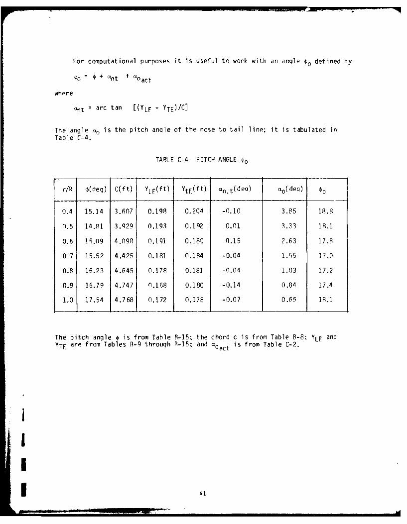
For computational purposes it is uspful to work with an anqle o defined by
o= + nt + 'Oact
whpre
ant : arc tan [(YLF - YTE)/C ]
The angle cto is the pitch anqle of the nose to tail line; it is tabulated inTable C-4.
TABLE C-4 PITCH ANGLE o
r/R (deq) C(ft) YLE(ft) YtF(ft) an.t(de q) ao(de q) o
0.4 15.14 3.607 0.198 0.204 -0.10 3.85 18.8
0.5 14.81 3.929 0.193 0.192 0.01 3.33 18.1
0.6 15.09 4.098 0.191 0.180 0.15 2.63 17.8
0.7 15.5? 4.425 0.181 0.184 -0.04 1.55 ]7.,
0.8 16.23 4.645 0.178 0.18] -0.04 1.03 17.2
0.9 16.79 4.747 n.168 0.180 -0.14 0.84 17.4
1.0 17.54 4.768 0.172 0.178 -0.07 0.65 18.1
The pitch angle 0 is from Table R-15; the chord c is from Table B-8, YLE and
YTE are from Tables B-9 through R-]5; and aact is from Table C-2.
41

Our first imperical correction is to account for the cascade effect. Thisappears as a correction to the pitch angle 0,; though, it is an actual correc-tion to the angle of zero lift. The corrected pitch anale o or is given by
0o cascade = 0o - Kgao * ao act (C.1)
where the correction factor Kga o is a function of a,, an angle which is ini-tially undetermined and o . The values of Kqa o are found in Burril 1944. If Vdenotes the resultant velocity and w the induced downwash, then Figure C-3 showsthe relationship between the various velocities and a,.
a 3 c / (T D r/R) (C.2)
Va x
Vrot
FIGURE C-2 SECTION INDUCED VELOCITY
42

The determination of *o cascade is part of the total interativP process todeterminp the induced downwash w. In order to start the process I is initiallyassumed to be equal to 03. 0o cascade is calculated based on this value, and theinduced angle of attack a, can be taken as *o cascade - a. Fiqure C.4 shows therelationship between the induced angle of attack, the angle of zero lift (10, andthe angle of attack of the blade a.
FIGURE C.3 INDUCED ANGLE OF ATTACK
Rather than solve for the downwash w, the itterative scheme is based on solvingfor aI . From Figure C-5
= o -3
]- 43

However, I should be defined in terms of the corrected pitch angle €o cascadein place of the pitch angle 4o; hence, our 0I is given by
= % cascade - al (C.3)
The induced angle al can be expressed in terms of 01 ; Burril (1944)gives the following expression for al
360 KE tan(Pl-5)2I - 2 sin P I tan (P-{) 1- (1-KP I) (C.4)n Kg5 Kso ta I0
The factor KE accounts for a spanwise elliptic distribution. Langan andWang (1972) show comparisons of experimental and theoretical lift distributions;the elliptic distribution is good for r/R < 0.95 but for greater values deviatesnoticably from the experimental results. For r/R > 0.95 the lift distributionis greater than or equal to the r/R = 0.95 value, and the value at r/R = 0.95 isa good approximation to the average lift distribution. Moreover, for a ductedpropeller there is even less likelyhood that the distribution would decrease tozero like an elliptic distribution at the tip. Since we will be using a numeri-cal integration scheme to determine the thrust and since the lift distributionover the tip region is better represented by the lift distribution at r/R =0.95, the value of KE for r/R = 0.95 is used for the value of K. at r/R = 1. KEis a function of the angle e;
= + (P - 0) (C.5)
Kp1 is the Goldstein correction factor for a three bladed propeller. Ks isa slope correction factor and Kgs is an additional cascade correction factor.These factors are to be found in Burril (1944).
Equations (C.1) thru (C.5) form the basis for an itterative scheme todetermine al, PT, and o cascade. To start the scheme assume Pi = 0 and compute
oo cascade use 1C.2) to get a starting value for al or use a value of al between-5 and 15. In either case use (C.3) to compute p, and (C.4) to compute a,out. If this value does not agree with the starting value of al, use it for anew value of alin (i.e. al going into the itteration) provided it lies in therange -5o to 15 ; otherwise, use another angle out of this range. Compare thenew alout with the alin. A good common sense choice of alin quickly develops,and convergence occurs rapidly. There is no need to change €o cascade or theK's for each new 01; simply wait for convergence with the wrong set of K's andthan adjust the K's and 0o cas. for the new PI. After the first few timesthrough there is little change in these factors.
44

I
Table C-5 shows the final results for €o cascade and Table C-6 presents thefinal iterative results for aI.
1 TALE C-5 COPRECTED PITCH ANGLE
r/P a BI(dea) Kgao ao act 0 (deg) ocas.(deq)
0.4 1.01 14.98 0.43 3.85 18.89 17.24
0.5 0.88 14.30 0.36 3.33 18.15 16.96
0.6 0.77 14.29 0.28 2.63 17.87 17.14
0.7 0.72 14.12 0.24 1.55 17.03 16.66
0.8 0.65 14.68 0.20 1.03 17.22 17.02
0.9 0.59 15.79 0.15 0.84 17.49 17.36
1.0 0.54 16.95 0.13 0.65 18.12 18.03
Equation C-2 is used to comp,,te a from the values of c in Table C-4. D8.50 ft. The hydrodynamics pitch angle al comes out of the iteration; thevalues in the table are the final values. Kg o is from Rurril (1944), aoact is
I from Table C-2 and o from Table C-4.
The final values of the factors which enter into the itterative calculationof Eouation C-4 are tabulated in Table C-6.
The theretical lift coefficient 2T I needs an experimental correction Ksand a cascade correction; the corrected lift coefficient CL' is given by:
CL' = 27T Ks K9 s al (rad)
These corrections can be thought of as cnrrections to the slope, thus thesubscript s.
There are three components to the drag coefficient. Burril (1944) qivesthe minimum drag component in terms of the following emperical formula:
I4
I
...I: ' . . . . . .... . . . -

C.
C- C-~j - -
4., LC) c to C)' 0 L-~ Csi -t~ m (%.i r C'SI q.
k-'c u- -* cI') ;: r- CC)C ~ to co U-) LA ) U C
C
5- Q -d' M - -4 \ LnLr -z m's 4.LA
kr, ("4 ('S ) ff) .- 4
c: c CO C- m C C'
a a. a - or cc o 4~
C c C; C; CZ
C cn C cn RT C (n
c LA) Ll Cr ko tC qC (-
ij rl, U LA lA Ln U-) LA '
C, ) CC, a, m X O l C
c. a-l a', m~ (Cr- m$
~CC C C
C C% LAr!' - a- i1 -4 COj - to) w
w.
- ~ ~ ~ ~ L ON qd ' ' .i 0
~ C'. C~j C') C:) C) (*
C:
W-) cc~ C 47 ('Si cc ON Ul
ui m A (
U' F.,0 - CO a-C
* . C- C C C -

C~min = 0.0056 + 0.01 t/c + 0.10 (t/c) 2 + K2
where the constant K2 can be determined from Figure C-9. The values of K2 inTable C-7 were obtained through linear interpulation. A second factor
\Cg =_E tan (Pi-0) CL180
is the induced drag component. The third component is a component depending on
how close to optimal lift the section is operating.
ACD = K3 (CiL - CLopt) 2
This component would be zero at optimal lift CL ; qiven together with K3Burril as a function of maximum camber and thickness Pchord ratio. There is acorrection to lift due to the drag; Burril gives this correction as
6 CL = CD tan (p, - P)
Table C-7 presents the values of all these lift and drag componentstogether with the final lift and drag coefficients. aI in radian is used incomputinq C L; otherwise, the table is straight forward.
Now the incremental lift dL = 1/2 p V2 c CL is perpendicular to the line ofaction of the resolent velocity VI , and the incremental drag dD= 1/2 pV2 c CD hasthe saie direction. Figure C-5. The incremental
Vro
riyure L-4 LIFT AND DRAG ORIENTATION
thrust dT and the tangental force dQ/r are related to dL and dP by:
dT = dL cos31 - dD sinPI
dQ = dL sinOI + dD cosp,
r
47

m .to a C) '0 m (\j koO'O ~ ~ 'OL C) 01 I CD C) C) C-1 LAr ko tn m0 r'- -
o * C\j -cs r- kc LA -4 0-J C) C) C) C)- C) a- 4= 1~) -4 -4 -4 -4 - 4 C
C; C) cz C) C) ) C
t Lr. kc n m C) C)m~ CO co ) C) co 00
%.0 %-0 LA) If) LA) -* 0 C \ ('.J l L) I.c -4 N-C) c) C) 4) C) C) C) m re) m' m~ ml 41* .
m-) C ) C ) C ) C C-1 C) C) C) C) CD C)1. C C CD)- C) C) C) C)- CD
CD C C) CD CD C a)~ C) C) C) C> C)- C) C),
'0 C) C) ) C C ) C
C)- q* a', ' LO O) _q C0 m KT C:) '.C '.0 LrCD LA) C) '.0 -z C'J C"j CD a) C) C'.j c C jC~ - -4 CD C C) C) C) CO cc r-- kr0 tco 4.0
C\j C) C) C C) C) C)- C; - C_) C) C) C: C) CDN4 C) C) C), CD C)- C) C) C) c C) C) C) C) C)
C: c: C) ) ) C) C) L C);C C; C) C) C) C)
- (NJ (NJ - to -- 4 N- U) CQ (J co C) -- 4 LA m (NJ'< qc M'l (J 1-44 C) C) I (j C) C) C) C) C) C)
If v' C)- C) C)- C) C:) C) CD C) C) C) C) C)I (- C)H E m C C C) C) CD C) CD C_)WE L C) C); C) C) C) C) C) U. C C) C) C C C)
- IC C C ) C) C)
m 00 r-) o-) cc LA L - co
LL. 4- C) crC N
0) C)=) C) C)
0) C C) C) C) C) C) C)-
C'.. '. 0) C ) O~i (N n C'> C) C) C)- c) 00C) Cn) x Ln C\.. a) r- 4r m' ('.4.
to 4 - CD C) C) C '-
cm E *ZI u C) C) C) C) C) C: C)
CO. LA') 0 1- C) k C\. -4l
J~l (NJ - LA -- 4 00C_) N- cc 4.0 LA Ln mN -44 1 -4 C)
- L CD r- LO Cfl ('4 ,-4 .- 4 U, *
- -4 C) C) CD C) C) C)> C) C) C) C) C. C); C
N- CD C) C) C) C) C: C)___________
LLJ C LO -: -z U-) m Ln
-i m' CV) 00 en) -:: a, ) m a) (7 cNJ 0) -C*)cc LO LA LA) '.0 '.0 ' r-.* *cC * * - '0 LfA LA; LA LA LA;
:be C; C) C) C) C; C; C;
Ln LA 4= C) C) C) 0 ) C' NJ O 0' L
m Kr L LO LO LO o(Ai o 3 o li a r, al 0m kc---; L
* * * -4 .- 4 .4C) C) C) C) c) C; c ea
~C) ~-4 C) LrA '0 '.00)D. LrA '.0 fl, m C) 0
t) .0 LO * m' mr N- 00 c m) 0O r- to0 10 ' LO"a CNj kc co LA, CY) LA) CD C) C C) C) C) C) C:)
- l * * * * C\;) C ) C C!
L;(.) C C C)- CD CD CD C)
SLO to0 N- 00 0l C) LA '.0 - co (3 CDL C C C) C; C) C3 a;C C) C); C; C) C)

1]
The total propeller thrust is
tipT=Z S dT
root
where Z is the number of blades,r or in terms of the discrete values in this report
IT = 3 * O.IR j dT
Similarily, the total torque is given by
Q Z tip d
root
or
=3 * 1R dQ
Results based on these formulae are presented in Table C-8. These resultsare computed for a water density p = 1.94 lb sec 2/ft . The values of dT, dQ/r,and dQ for r/R = 1.0 have been cut in half to reflect that the interval overwhich these increments act is half the size of the other intervals. The inter-val t around r/R = 0.4 enters fully into the calculation; however, the blade
- for r/R<0.35 to the hub has been neglected. Note that 'he prcpeiler hub has a1.0625 foot radius which corresponds to an r/R = 0.25. By neglecting the por-Jtion of the blade inboard of r/R = 0.35 we are then neglecting 0.425' = 5.1" ofthe blade. Within this segment the hydrodynamics is not as straight forward.As can be seen from the results at r/R = 0.4, the loading is small, and theresults will not change significantly.
iI
I
!I

vi
- f co Q Ce N- r-. CI~ LrS LA) -z I.C %r_ LA U C)
C' ql kc -; C\J C\J LO m~-a -4 ('1 -gz to co w I
C,L-o
4-~
0 c'. m'~ Or, :j CJ (\J C)- q r C'j Tr N- 1: 1-4 C,
LS: -- -j
L)J
4-~ LO
LJ tfl (n C) a)r 0) Lr C-i . Kt~ M- -c - cj (-- 1 1
LUJ -- -4 % C LO ('.4--
C -vjcc-
co
6 m ~ -1 M c -4 -4d o C) j LO. in i cc$4 C) LA
I-. -o c q2
-c C
4,)
Lf .- 4 t C') 0. LA m0 LA O8. C ) 0 -LA W r)- Lo
J -4 C\j cl LA) 10, 1 LO
0) C ' ) o ~-4 C a) C- IC c 10
C-- C)C C$ C C C C)C Co C) C C: C c0
C C' C C 0 04-
m' LrA -4 k0 %D m' C\j u ..- 4 Id fl -4 -4) -4 0C
* .0 4-'0D 0; 0> 0 0 c. 0. .0 - 4-
0) co 0) a. C~j 00 m- LAI *cY) LA,
-1 1- - 4 -4 -.4 1 4
L0 j) CD 0a -4

The velocity distribution is obtained using the Goldstein (1952) approxima-tion. In ",is method the velocity on the surface is given by
v-eCO (1 + £)1/? 2 CL 2 sin (o + c + a) CL COS (0 + E: + 0
(n' + ., n z a0 a0+ CL (C.6)
2 IeC °
where 0 and W are transform plane coordinates given by
x = / C (1 + cos
y = 1/? C * (0) sin €
The angle E (€) is given explicitly in this approximation by
211
(€) = (1/2) P ' (t) cot 1/2 (o-t) dt, (C.7)
0
CO is a constant for each section, and it is given by
211
CO = 112 (i/2) 4, (0) do (C.8)
0
If a satisfies the condition
-C12 sin (c + - CL cos (E + 0) + CL 2 (C.9)
a 2) a o 211 eCO
the Kutta-Joukowski condition is satisfied. CL is the left coefficient fromTable C-7, and a is the left slope corrected for viscosity; ao = 211 Ks where Ksis from Table C-6.
0 is determined through an itteratine solution of Equation (C.9). C., theangle c, and its derivative c' are computed through the methods suggested byThwaites (1960). The results for sections at r/R = 0.5, 0.7, and 0.9 are pre-
* sented in Table C-9 through Table C-11.
i.
o9

OL -4 krd Lc\--i C:C )C- C)m n C C j\ c-
Vr CCDC CCC CC CC CC-cC
Lr
CUL--
r-) o* a. M ( cn~ Cj i r- C'.J k C)% cinLc C) -4 -0 C-) r-.0'n~n acO-.n ~ Oni(C\J C c Cs j r- 00
C'j C'.j -C CIDa) ) ) . ala)a)0 O a O oll 0)Ocr-
- -i4 - _: _-4 C C CC c C CCC C; C CC;
U-
.LUJ
C
- - (\ ' -t C c - ZT C.4 0 ' %Cr- mLOJ-::r ) -~ CD - (= ta C, -O C\o--.~.4.a C O'zr
-> C C C: C - C -- - C-4 L-4 -: .- ' .I - CD C C
C-
(* f*- cc a (7 0 C) C r-. (Co ' r -0- n(0~'
OCT %C * .n t. 0r r \ ~ ,0 -tU cVk
4- -- C OCCO LC-404C) JC.Cm' t.0' mC))00e4 MLOr 0O
LUJ
C I ..
Lu CDC OCCO O 000 ~ n L L zr -00 OCCOC 3 aI-b j _ __ _
LLJ 3 C C; ; c c c C; ; C C; ; C- C.C D L

N -- - (~ - m) - kD ( ) (\J C ) C 'j k c k rC ( r N - c r 0 .1 a ,
IfC- Da cC --c ~C>C) C)C C )I= C) C -- c ~C c p
C) -
I-C)c cc 00 -) cc I- tz U) 00 U)C\j .- , M~ U) u Clcc~a 1 ccNN-.0 LI, - O ol al> C., C C!cfo'iaa a ooa a a Oo i~ oC ~ ooccl
Q. -4 c)) C_-C) C_-C)C) C) C CDC) c C C--CC) C.
Li-
C)__ _ __ _
-,L0Ccc -NL.JcCJ .i---.O
V) ', 0---c- G CJCC C) C)iCDC) C) CIL I! I- li I . . . . I I Il C\!
C
0Co Co C C) 4-C)C) -t C).-4 C> C r cc, C)mco C)
0. > C) ~4- - - - - - - - 4.4,4 C) -4 C C;
w 7 crI C .- mk 0 c 0C rm D0 \ ' 0 M
x C)J0c C) C- CC cl \ l ccc.J0c .
LL;J~ %Jj'~ c LSt
C)
F-
dcA

C)
-4-jm \ .TC r d -~ tk t o o r OrlO
B~ 000 CC) t0 0 0 00 00 " 0 00000-d a ) -
> . . . . . .
L -4 C) -I 00 0 0000C :) C C 0 0 0000C C
LL-U-LAJ
m- -~ Ir - tr 000 - - C)t 'J- -C -
LI) CL ~ -m C)~Oa C)0 C )C )C C )C ~LLJ 000 000.0 0 .0..0-.. 0.9 9 .
0444 C) C) a C: C)
a.. lii 11 11 1 111L1n
CD C:,A
C-)
0Lj 4 C l- OlO(f LlO C%j )OC.O CD u.OrCJQ
co 000 O-s-: -4( 1C9 Cl
(%) __M______ C,_ L o O ) o d
s-r 4.0 M OOcLn e'J 0 c Y s q,"* o "0"10L C JfO C0r- 0CU'J C; ; 0 C;C; ; C
m- C 0 0 -ICJC. ~ ~ o r ~ O~O

From the Bernulli equation
P atm + /2PV2 + yh = Patm + Pl + 2P v2 + yh
where @I is the local gage pressure on the foil minus the static head. y = 62.4Ibs/ft is the specific weight of fresh water, and Patm 14.7 psi 2116.8 psfis the standard atmospheric pressure. p = 1.94 lb sec Ift . The water depth hwill be taken as the depth of the propeller axis below the design water line,7.5 feet, minus the section radius.
h = 7.5' - r
I The local pressure Pl in terms of the local velocity v is given by
2 2j P1 1/2 P (V2 - v );
a local pressure coefficient Cp can be defined byi 2 )2
Cp =P/I/2 P V 1 - (v/V) (C.10)
Values of the pressure coefficient for r/R = 0.5, 0.7, and 0.9 may be found inI Tables C-9 through C-11.
For cavity free operation the local absolute pressure must exceed the vapor1 pressure e, that is
Patm + P1 + yh > e
1 orCp > e - Patm - yh
12 P Va2
Our analysis of cavitation is based on a summer time operating temperature of70" F; at this temperature e = 0.36 pse = 51.8 psf. Table C-12 presents con-ditions that the pressure coefficient must meet for cavity free operation. Thevelocities V are from Table C-3.
1TABLE C-12 CAVITATION CRITER
r/R yh(psf) e-yh-patm(psf) V(ft/sec) 72pV (psf) Cp >
0.5 335.4 -2400 60.49 3549 -0.6760.7 282.4 -2347 84.50 6926 -0.3390.9 229.3 -2294 108.61 11442 -0.200
Cavitation occurs at the face side of the leading edge at r/R=O.9 tor/R=O.5; although the actual value of Co at r/R=O.5 is not below the criticalvalue, it is very marginal. Cavitation also occurs on the back side at r/R=0.7.
55
- -

APPENDIX D: STRUCTURAL ANALYSIS OF THE BLADE UNDER ICE LOADING
As mentioned previously ice loading is difficult to predict; as before, thecriterion proposed by Graft (1977) is used. The blade should be able to supporta load equal to the crushing strength of the ice times the appropriate projectedarea. The rotating blade could be crushing through an ice chunk in the way ofits rotational motion; in this case the projected area is in a radial plane thatis a plane containing the axis of the shaft and a radial line. Ice could beforced against the blade in a forward or aft direction, in which case the pro-jected area of the blade would be the appropriate area to use; however, in ouranalysis the developed area is used for convienance of calculation. The substi-tution of developed for projected area is slightly conservative in terms of pre-dicted loading and stresses.
Tables D-1 through D-3 present the section properties for r/R=O.4, 0.6, and0.8. The first eight columns of each table correspond to the respective columnin Table A-I. Ix is the moment of inertia around the centroidal axis parallelto the chord. The remaining columns are used to obtain x, y', and Ixy , where lyis the moment of inertia around the remaining centroidal axis.
TE1V=- x dA
L.E.
= 0.05 C/A J x (yu-yl)
TE
- 1/A f (x-7 2 dA
L.E.
= 0.05C Z (x-7) 2 (yu-yl)
and
Ixy = 0.05C >. (x-7) (y-T) (Yu-Yl)
Table D-4 presents the corresponding data for an NACA 0018 synmetric foilsection with a 1.5 ft chord. Only yu is given since yl=-yu. Also7i for eachsection is 0 as is y; thus, (Yl-Y) dA is also zero. Ix is dependent solely on
56i
56 - v

c )tz C & & c? C 00C)00 000 C 0 C. C)C CC ) )C ) r
0~ C. -A CJC~' (n ..CT C14 -4 ~~ 0 -4
00 00 0000 0000 0000mU fl0 0Cc C)0 00 00c , C 00 D00CD000 C) ~ 0,4 DC '
N 4-1
-- 1,00071 C--4 c'0-ie'i O -4 W* coo~~-c 0~ lIl ,0 - -400C- 0 D0-4 -- 4- 0000 C0000 D C-c 0 0
9 I> 000000 R C : 9 0000 00 CC 00-IC 0
C* r. Il Io CD In In ccIId - 4m
>1
1.-
LJJiI-m
Lhli
CC a% ., -a %0CI oc 0 0C )c
m ~I to al (N m Ic Id In In .0 I = c - q
4
IJIt
un I'M 0to InCD o 0Ul InCD n 0__ _ _ _ _ ___)_ _ __ _ __ _ ___ __ V- r.( 1t l ) V o10Il ,- 0 001C
C; -: Cr;

In M W -r - -1* -Ftl o - 1- C~ ce)C111 C .1r 0 CNJ-I* CN 0 C)
C>C
IXI
-S-
L.J
5 C:
0 0c (.r, 0) m 0 - ~ Cjm0 %0C~C Ln kD -Lt) 0 r--4 r- -0- - C 00 0 0C -0000,m0 000D-400 000 0
I-n
-j Im ~ x a 0LO D m m m -4 LC L(r.-4 LO co 00 0. Cm t r Do ) C
C)- 0 C%J oC C'j -4 -40 C . -4 -4 c\JC% C%j C'.j.- CD-4 CR c; Cc 0000 0000 0000 C;C ;C ;C ;C ;C;a
a tzL~t~ In Inm irW nc)C~ 0 0 %mcC 00C -14\J 1
-4 -4 -4 4-q40 C 00000 C C 00000 C)11i
4-0 7 1 C Uc) M C 0rl r-. C.Jr-- r- o o 4 C%j M l oe -0 0) CD C
CD ON o D -ON %o 0 c ~ 0 fl0 C) 1)C\ \J 00OOC)- 0~J~~C. C~JCJ-40 0-4 -4 \jC. "%.44 CD In in)
xI
C-)0I r C0lu~i O~lLr lO LC Qin~ 0uCD ~ .4 ) nCDI
000 0 000 C 0C00Q C

C:) 0-4CCm-rLO 0.-4.C) q-4 C)0OD tL0 m c\J.C) C LC)C-' C00ac0D00 0 0-4 -44 - 000 000 0= - )C )C ) CCDC>CDC 00000) ) )C C 0000 0 0C> 0000 -4C )(= C
4- -T.t 4-4
N 4-
I IN0Cmc) J-40 ) 00C'C -4 -4 -4 -4'--400 C)C .)-4 C'.JC r--
a 00000 0 C 000= 0 0000 0000 co 0_ )C )(-C )C
C) 00 00 0000 00 0 0c0 0) C ;C ;C C ; ;C C ;C
-4
Nl
I-
LJL
4- koCr- V) M %C ~ -co -4m D o Clj In CD0Coa.- I rL ~ 4 - C. C& - ) ' .Q-4 C> 0 -4 kc 00
-~~~+ - hllg *u
I>. 4-~ 04 U
<. 0 ICJM4-I ot.t ot nL - r
ON 0000 mV o torOO o00 00 0000n 0 000-I C4 00 0
4- C' CC% ~C%.'Cli C J ~ C ! C'CJI"CC! l CC'. C "!\~ Olt .'c\ i-:
jM N
It Ic 0n< n0L D n0u a t 0U)OU 0 u 0 u, :)In0 -
0000 cC0- 00 0 0000 n 4 .I L ok I.r, C C NC

M Y r O n r- . Ln N..M l (c00 , C) D 0DOM C- U-)-O E -4 4. --1 0C -4 -4 C\J -4r- C14 LO~ kc N. 0) ar)
0000 00 0 00 00 0 00
4-,4
I 0lL C- MO ("1 -4 C--... C m.,C) C)'.00r I( 0" N Ci.0 ~0 .- 4 O Cr' C
IIC;C 0(J~\C\I C;C -C;C;C;.000 C C;C C-- iC. V\'CD cQI 0 0 0 0 0 0 0 00 0 0
C: 4- I
x C) n mr- m-1 mtr \ic. M C 0~C.0 -4 U'oeC ' o 0CO %D 0 ON C Mco UJ') -4el U) -'.00 O~~.c,- C)
.00 -4II4k 4 t ~ P - oMc C) CJr ~
4- m f-. V) C'.4'-) 4C L -4~ C: iW D 0C rt kC.Cj I
I ) %r 00 .-- 0 0 0 0 00i-4qt F -4 0 0 0 --4 z-4.-4CD 4-
I; CI% 7 nr nMO - oM C Nt ~ >c
N!C R 1 C : L
~ * 0Ca 00 00 0000 0000 0000) DC C . C)C C 0 0 0)C ) C
Ix
C 0Lf)0CDLt0L 0UDI.A0 'fC U)C 4nLC)Ul) C 0Lt)O0LCO CD
00 00 0000 r C % v 0 0000 000C!%0% % C 7!a
0 C> C00000 C -4 -4 -- 4~ C)44.4- 0000 C('4C, C
C)
C) C C C, C C 4= C Cl0 C) C) Cd0 C C) ) C C, I- li
- 4-
4-4
>000I0 0000 -000 0000 -- -0C C 4- 4-4- 4C
C)C)C)C C- . 0000- 0 00 0 00 00) 0. 0)C Dc C) )C >C I C=) CD 0000 00000C= C C-C IDC C (-C 0C - ) C
4-)
Cl4-
m~ M C~ -4 -40 C)4 C) C .C) C-4 -4 .-4 C, r-4-04 -~ -I 0 e
1.--
LnI-4
LU0 4CD
4- ~ O ('4U LC~O0('j ~ OO1
W, C% m C -4 -4 .. . ."I 4C n0
+j-P
CC4-)I
LU<
0 4 ' C l 0: Q, 00-44-- (J C'C> l % 0 D nC W) .-. -00*x*000 0000 0000 00 iC "!l !ll a !000 CCD 00o 0 0000 00 0 000QQ0DC C- C QC Cla 0 0

4-)
>1 C DC -) - c nC.-0 CiU)0 o oC >C
C)- 1M(I C- C)C: - Dc> C >C CCJCd% 4 0000 0000 0-4 -4 C'j LO~CD 0000 0000 0000C DC)C C )0 0000 0)C ) C )C-C , C
x .D C) C)C )C )0C ;C C C ;C ;C ;
CD\
4-I.--
X ) - co %C.J () CJ0C' O 4DC r~lLO~VO 01 % C i Ln ) C LC)
--- C) COOr- qu- -4 c W " 00C 0C'j q, c 'D C) 'oo (%J
l I C4 IRC 9
I CN
4-)-
II
K C 0r C%Ir- U' coa2 ~ -IfLn-4 00Cl. 4- ccC\j --z t (1 0 0 4-
C) 00 .- fC)0) 0000 000. .- 4400 0~ : l rr oC ,a . C 4-)
CO I II I II I I Il
M 4DR -f ON-U)O(" c Cd -N-O, r A- D CO Q'
-4 .c -4.- 00U) q000 ~ 4 lrr-C - C 000 -4-CD m
4.)
oCD Qol 0% . C) j CjU % 0C -O4 N- C) ~ M 4-)4 D 00-4.-4 -40 0000 0000C.CDCDa-4 -4 -400CD 0 CD c
>) . . . 0
x 11
- 0IfL0 DU')C-Ln > ') 00Ln C0 tLC DLr)0Lt 0LfC U) Lnu0 'U4
OOOCOO4( 4 c RtU W Ct r C 0000 000 0 0.D
C_____________C ________ j ______;_______________C__ ______C__________________ _______________C ________

-4 0LL4'-4 0 0 0 .4 ~ C'r ~ ' J
- 0o oe 0000 -- I~c~ alooo V)C)(-c 0-t 40 r r CCj .x- )L - :tCj1- : )C D- "ooo Ccoo 0M0 oc o C 01
L) _ _ _ _ __aC DC )C)C )C PcC C C - l -
CCD CCDoc C, oC) c 00 0 0000 0 ) C )C )C
LA- I I I I I I I
cm4-' .4J'C O
- 4-C- c % o c C)O~ .- 0*'0)C -ic.0r-, e 0 a,- .4 r
C C -ll 0 JC'j -4 C CC UD r -4 0 4M4--L r U-)%:rmuC C, .- 4C-- c,-4 -4 -- 4 -4 0000 c0000 , ) 0 00000 -- C C ) z
LL .4-. .
LW~
0C> ' , q 4 4 -.L~f -4 -4 q C) C c .. , -- C- L4- - )(-C cC- C) 0Cc~ cZ c LCAC D -
m. 4- 0_ 00 00c0)0--(=0 C).0C00)C; 0 00 0 C) C) C)C < C-cC;~~~~~~ ~ ~ ~ ~ ~ -: C ; C = ( ; C ;C 2 C
a> ) 4 a00r- 0u L-4 00 C~ LC)LraeS04Ci -)% c a k0: %,-I :TLO kc r U ' t CNJC C 0( t )t .- O , C) LAO
- ! 0-l\C! C'.C C %.., CJCJC'.C\Jcl C4 CJ.-! -- i- .- ! 00 'C. C 9
-J C)-r _:
I- C
CD - CoD C C'.) r0'.~ -C0-r- 4D0 C) (NJC C ,q=C 6
4-
.- ' = q= 0 CD C) Qe.L~- tC 01 C'J)r-.u)
0 0000 0 0000 0000 LnC00DonqL c o0 Lna Lx~~ii . a! Iii IiC % ' V l :L l l l l 1 C
4.o o o c l C D0 4 =C

I
Actually, the moments of inertia around these axes are needed but with thesection rotated through an angle equal to the pitch angle. If the new coor-dinates are denoted by x' and y'.
x' = X cos 4- y sin
y' = X cos 4 + y cos
The desired moments of inertia Ix' and ly' are expressible in terms of the pre-
viously calculated Ix, ly, and Ixy.
Ix' A Y,2 dA
= A (x sin 4 + y cos 0)2 dA
= A x2 sin2 4 + y2 cos 2 0 + 2xy sin 4 cos 4 dA
Ix' = Iy sin2 4 + Ix cos2 4 + 2 Ixy sin 4 cos 4)
Similarly,
ly' = ly cos 2 0 + Ix sin 2 0 - 2 Ixy sin 4 cos 4
The loading is also computed with the section at the pitch angle 4. In thisposition the force normal to the x' - axis at a given value of r/R is:
Yi = 0.1 wRc i cos Oi
where w is the loading per unit area and c; is the corresponding chord length.The force parallel to the x' - axis is:
Xi = 0.1 wRci sin 01
The moments that these forces exert on each section are tabulated in TableD-5 for an icecrushing stress w = 300 psi. Ad and A, are the outboard pro-jected areas; rd and r. are the radial locations of the centriod of therespected areas.
The maximum tensile stress will occur at the leading or trailing edgedepending on whether the ice is pressing through the blade from the forward oraft side of the screw. If z denotes the maximum distance from the centroid tothe leading or trailing edge parallel to the chord,
Zb = (C/2 + i) sin *when computing the stresss due to the moment Md and
Z, = (C/2 +i) cos 4
when dealing with Ml. The stress is given by:
Mz
I
L 64
I
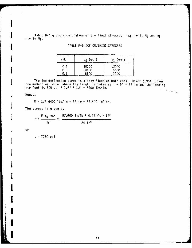
jTable fn-6 qives a tabulation of the final stresses: Jd dile to Md and o]due to M1.
jTABLE D-6 ICE CRUSHING STRESSES
r/R Od (psi) oi (psi)
0.4 30300 120000.6 18600 56000.8 8800 2900
The ice deflection strut is a beam fixed at both ends. Roark (1954) qivesthe moment as 1/8 wl where the length is taken as 1 = 6' = 72 in and the loadingper foot is 300 psi * 1.5' * 12" = 6400 lbs/in.
Hence,
M = 1/P 6400 lbs/in * 72 in = 57,600 in/lbs.
The stress is given by:
M Yu max 57,600 in/lb * 0.27 ft * 12"
Ix 24 in4
or
IS=7780 psi
III
I
1 65

CO COoOC'
i +~ ~ I 7
cm: - 0 L)M --j
co
0 * C 000C000 C
00. Cj a -a 4 -a aa j a IC)~ _ I-z c) -tr cjQ ,1-4mC'i C m CO- 4 ICT
CD 0 . . sk o l
4- aN 0- c>J cl Lo q-J LC: I O -4C>U -
-LJ
- 0 -0 0(Ir 4L
4- -d o 0') - -4
'- _O _ _ LO''U4-- - n C
4-m 0 0q*o
cOj MC\%j r4 4-4 -4 q
* 4- 0 '4
004- -4...o
UI

INIT[AL DISTRIBUTION LIST
No. of Copies
CoImmandant 6U. S. Coast GuardWashington, D.C. 20563
Defense Documentation Center 20
Cameron StationAlexandria, Virginia 22314
Assistant Librarian 4Technical Processing DivisionU. S. Naval AcademyAnnapolis, Maryland 21302
Academic DeanU. S. Naval AcademyAnnapolis, Maryland 21402
Director of ResearchU. A. Naval AcademyAnnapolis, Maryland 21402
Division Director
Division of Engineering and Weapons
U. S. Naval AcademyAnnapolis, Maryland 21402
Department Chairman 2Naval Systems Engineering DepartmentU. S. Naval AcademyAnnapolis, Maryland
Professor T. J. Langan 3
U. S. Naval AcademyAnnapolis, Maryland 21402
.1
"V
I5....I," -I -t .. ..