Embed Size (px)
Citation preview
E.G.S. PILLAY ENGINEERING COLLEGE (An Autonomous Institution, Affiliated to Anna University, Chennai)
Nagore Post, Nagapattinam – 611 002, Tamilnadu.
Rev.0 COE/2017/QB
1701GE101 BASIC ELECTRICAL AND INSTRUMENTATION ENGINEERING
Academic Year : 2017-2018 Question Bank
Programme : B.E - ECE
Year / Semester : I / II Course Coordinator: A. Sundar Raj
Course Objectives
Course Outcomes:
1. To acquire the basic concepts
of electric circuits.
2. To understand the construction and operation of various AC machines and DC machines.
3. To introduce the principle and application of Transformers.
4. To gain knowledge about units, standards, error analysis and characteristics of measurement systems
5. To learn the behaviour of different sensors.
On completion of the course, students will be able to
CO 1: Understand the basic concepts of electric
circuits.
CO 2: Classify the AC machines and explain their
operation. CO 3: Explain the working of DC machines and its applications. CO 4: Describe the principles of operation of Transformers
CO 5: Identify the types of measurements for
instrumentation systems
CO 6:Select suitable sensors used for various applications
PART – A ( 2 Mark Questions With Key)
S.No Questions Mark COs BTL
UNIT I – ELECTRICAL CIRCUITS And AC MACHINES 1 What are the types of single phase motors?
2 K1 Induction motors
Repulsion motors
A.C. series motors
Un – excited synchronous motors
2
2 Why a single phase is not a self – starting? 2 2 K1
Alternating or pulsating flux acting on a stationary squirrel cage rotor cannot
produce rotation.
3 What could be the reasons if a repulsion-induction motor fails to start? 2 2 K1
No supply voltage.
Low voltage.
Excessive overload.
Brushing space may be wrong.
4 What are the advantages of leaving capacitor permanently? 2 2 K1
Improvement of over load capacity of the motor.
Higher power factor.

E.G.S. PILLAY ENGINEERING COLLEGE (An Autonomous Institution, Affiliated to Anna University, Chennai)
Nagore Post, Nagapattinam – 611 002, Tamilnadu.
Rev.0 COE/2017/QB
Higher efficiency.
Quieter running of the motor.
5 What are the advantages of polyphase induction motor?
2
2
K1 Simple and rugged.
Low cost and very reliable.
High efficiency.
Minimum of maintenance.
6 What are the two types of rotors used in alternators? 2 2 K1
Salient – pole type
Smooth cylindrical type.
7 State ohm’s law. 1 1 K1
The ratio of potential difference between two points on a conductor to the current
flowing between them, at constant temperature.
V = IR (at constant temperature) 1
8 State Kirchhoff’s law. 1 K1
1. Current law(KCL)
Total current leaving a junction is equal to the total current entering to that
junction.
1
2. Voltage law(KVL)
ƩIR + Ʃ e.m.f. = 0
1
9 Define RMS value. 2 1 K1
Steady current when flowing through a given circuit for a given time produces the
same heat as produced by the alternating current when flowing through the same
circuit for the same time.
Im/√2 is called rms value.
10 Define peak factor. 2 1 K1
Maximum value
Ka = = Im / Im√2 =1.414
r.m.s. value
11 Define form factor. 2 1 K1
r.m.s. value
Kf = = 0.707 Im / 0.637 Im = 1.1
Average value
12 Define average value. 2 1 K1
Average value of current = 0.637 * maximum value
13 Define power. 2 1 K1
Rate of doing work. Its unit is watt.
1W = 1J/s.
14 What is voltage regulation? 2 2 K1
E0 - V
%regulation ‘up’ = *100
V
15 What is maximum power output? 2 2 K1
E
Pmax = VImax cosφ = VImax
√E2 + V
2
UNIT II – DC MACHINES
1 Write the equation for EMF induced in a generator. K1
φPNZ
Eg=
60A
1 3

E.G.S. PILLAY ENGINEERING COLLEGE (An Autonomous Institution, Affiliated to Anna University, Chennai)
Nagore Post, Nagapattinam – 611 002, Tamilnadu.
Rev.0 COE/2017/QB
Eg –generated emf ,φ- flux per pole ,P- no.of poles , Z- total number of conductor,
N- speed of the generator , A- no.of parallel path
1
2
What are the types of DC generator? K1
Separately excited 1 3
Self-excited
Series generator
Shunt generator
Compound generator
1
3 What are the characteristics of DC generator?
Open circuit characteristics
Internal characteristics
External characteristics
2 3 K1
4 Define armature reaction. 3 K1
Armature conductor will produce some flux, this flux disturbs main flux. 1
Due to voltage drop, will occur in armature. 1
5 Define back EMF. 3 K1
This EMF always in opposite direction in supply voltage. 1
φPNZ
Eb = volts
60A
1
6 Write the torque equation for dc motor. 3 K1
1
Ta = φ Ia * Pz / A
2П
1
Ta- armature torque , Ia – armature current 1
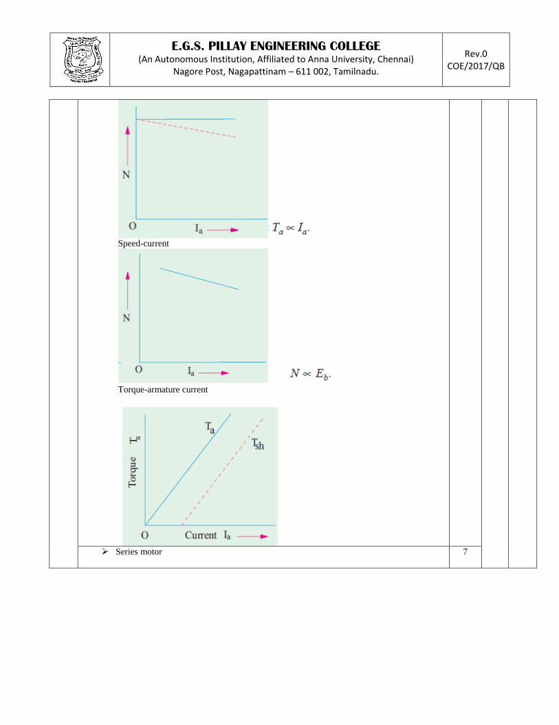
7 What are the characteristics of DC motor? 3 K1
Shunt motor
Speed-current
Speed- torque(mechanical)
Torque-armature current(electrical)
1
Series motor
Speed-armature current 1
8 What are the methods of speed control? 3 K1
By varying the resistance
By varying the field flux
By varying applied voltage.
2
9 What are the types of compound generator? 3 K1
Flat compound – Eg = V
Over compound- V>Eg
Under compound- V<Eg
2
10 Give the equation for critical speed. NC 3 K1
BC
NC = *full speed N
AC
2
11 What is the voltage of a motor? 3 K1
Overcome back EMF,Eb
Supply the armature ohmic drop, IaRa
1
V= Eb+ IaRa 1
12 What is the principle of DC generator? 3 K1
Whenever a conductor is moved in a magnetic field, emf will be induced in the 2

E.G.S. PILLAY ENGINEERING COLLEGE (An Autonomous Institution, Affiliated to Anna University, Chennai)
Nagore Post, Nagapattinam – 611 002, Tamilnadu.
Rev.0 COE/2017/QB
conductor.
13 What is the principle of DC motor? 3 K1
Whenever a current carrying a conductor is placed in a magnetic field, the
conductor experienced a force.
2
14 What causes heating of armature? 3 K1
Eddy currents.
Unequal strength of magnetic poles.
Operation above rated voltages and below normal speed.
Moisture which almost short circuits the armature.
2
15 What are the causes of hot bearings? 3 K1
Lack of oil.
Belt too tight.
Bearing too tight or not in line
2
UNIT III – SINGLE PHASE And POLYPHASE TRANSFORMERS 1 What are the types of transformers?
4 K1 Two types: Core type
Shell type
2
2 Define voltage transformation ratio. 4 K1
E2/E1 = N2/N1 = K 1
K is called as voltage transformation ratio.
V1I1 = V2I2 or I2/I1 = V1/V2 = 1/K 1
3 Define voltage regulation. 4 K1
V2 No load – V2 Full load
Voltage regulation =
V2 No load
2
4 Why transformer rating in kVA? 4 K1
Copper loss depends on current and iron loss depends on voltage. 1
Hence total loss depends on volt ampere not on phase angle between voltage and
current. (i.e) power factor.
1
5 Define efficiency. 4 K1
Output
η = η- efficiency
input
1
Output power
η =
output power + copper loss +iron loss
1
6 Define all day efficiency. 4 K1
Output in kWh
η all- day = (for 24 hrs.)
input in kWh
2
7 What are the losses in a transformer? 4 K1
Core or iron loss
Eddy current loss
Hysteresis loss
Copper loss
2
8 What are the advantages of three phase transformer? 4 K1
Weight less
Cost about 15% less
It occupies less floor space for equal rating
2
9 What is the drawback in three phase transformer? 4 K1
If anyone phase becomes disabled, then whole transformer has to remove for 2

E.G.S. PILLAY ENGINEERING COLLEGE (An Autonomous Institution, Affiliated to Anna University, Chennai)
Nagore Post, Nagapattinam – 611 002, Tamilnadu.
Rev.0 COE/2017/QB
service for repairs.
10 What are the types of testing of transformer? 4 K1
2 types:
Open circuit test
Short circuit test
2
11 Give the formula for eddy current and hysteresis loss. 4 K1
Eddy current: We = QB2
max f2
Hysteresis : Wh = PB1.6
maxf2
2
12 What are the advantages of shell type transformers? 4 K1
More rigid core.
Lesser weight.
Lower iron loss.
Lower cost of manufacture.
2
13 What are the uses of auto transformers? 4 K1
Interconnecting transformers.
Furnace transformers for getting convenient supply.
Auto- starter transformers to give upto 50 to 60%.
Give small boost to distribution cable.
2
14 Mention the factors on which hysteresis loss depends? 4 K1
Quality and amount of iron in the core
Flux density
Frequency
2
15 What is the condition for maximum efficiency? 4
Copper loss = iron loss 2
UNIT IV – INSTRUMENTATION SYSTEMS
1 What are the major sources of noise?
With the QUM.
With the electronic signal conditioning system.
Analog to digital conversion process.
2 5 K1
2 What is anti-aliasing filter?
No significant energy.
Low-pass filtering before sampling.
Necessary for accurate digital signal processing.
2 5 K1
3 Define errors in measurements and its types.
Intrinsic properties of the measurement system.
By system redesign.
1 5 K1
Types: Gross errors, System errors 1
4 What are the types of standards?
International standards, Primary standards, Secondary standards, Working
standards.
2 5 K1
5 Give the equation for quantum hall resistance RH 5 K1
RH(j)=EH /IX=RK-90/j=h(q2j) Ω 1
h- Planck’s constant, q- electron charge, j- step number, RK-90- von Klitzing constant 1
6 Define charge amplifiers.
Electrometer (FET input) op-amps.
Ultra-low dc bias currents inputs and ultra-high input resistances.
1 5 K1
Measure pressure and force transients.
Measure the coulombic charge stored in capacitors.
1
7
What is Toroidal inductor?
Made from one or more turns of a conductor, 1 5 K1

E.G.S. PILLAY ENGINEERING COLLEGE (An Autonomous Institution, Affiliated to Anna University, Chennai)
Nagore Post, Nagapattinam – 611 002, Tamilnadu.
Rev.0 COE/2017/QB
Wound as a solenoid, either on an air core, or a ferromagnetic core.
1
Made of ferrite ceramic or laminated iron.
Wound around a ferromagnetic ring or ‘doughnut’,
8 Define Q-factor. 5 K1
Ratio of the inductor’s inductive reactance to the real part of its impedance. 1
Q=XL / RL = ωL / RL 1
9 What are the applications of pressure sensors?
Aircraft altimeters,
Submarine depth meters,
Pressure meters for gas tanks,
Medical/ Physiological pressure sensors for blood,
Kidney dialysis pressure,
Hydraulic system pressure,
Generators, Diesel engines,
Purge liquid pressure in oil well reconditioning, etc.
2 5 K1
10 Define voltmeter sensitivity.
Full scale voltage of the meter by the power dissipated in the meter at full scale
voltage.
1 5 K1
η = VFS / PFS =VFS /( VFS2 / RM)
1
11 What is meant by Kelvin and Wheatstone bridge? 5 K1
KELVIN: Used to measure very low resistances, such as ammeter shunts and motor
armatures.
1
WHEATSTONE: High input impedance voltmeter, then in the null condition is 0. 1
12 What are the types of DC voltmeters? 5 K1
D’Arsonval meters, dynamometer meters, capacitor voltmeters, electrometer
voltmeters, chopper type Nano voltmeters, and thermocouple voltmeters.
2
13 Define spot noise factor. 5 K1
Ratio of the signal to noise ratio input to the signal to noise ratio output. 1
FSPOT = SNRIN / SNRO 1
14 What is meant by analog hall effect sensor? 5 K1
Measuring either constant or time varying magnetic fields. 1
B(t)cos(θ)IX(t)RH
Hall sensor EMF =
H
1
15 Define SQUID. 5 K1
SQUID stands for Superconducting Quantum Interference Device.
Used in biophysical measurements in neurophysiology.
1
Boiling point of liquid He at atmospheric pressure (4.2 K).
High temperature semiconductors operate at temperatures up to 125K.
1
UNIT V – SENSORS And APPLICATION 1 Define sensor
Conversion of energy from one form to another. 1 6 K1
Eg: convert temperature to voltage. 1
2 What is a Resistive temperature sensor?
6
Metals and alloys increase with temperature. 1 K1
R(T)=25R+ α(T-25)+ β(T-25)2
1
3 What are the types of resistive strain gauges?
Bonded and Unbonded gauges. 2 6 K1
4 Write the equation for resistance of the wire.

E.G.S. PILLAY ENGINEERING COLLEGE (An Autonomous Institution, Affiliated to Anna University, Chennai)
Nagore Post, Nagapattinam – 611 002, Tamilnadu.
Rev.0 COE/2017/QB
R=ρL /A Ω 1 6 K1
ρ – resistivity L- length of a wire cm A- area of a cross section cm2 1
5 Define Gauge factor
GF = ∆R/R =∆R/R
∆L/L ε
1 6 K1
∆R – change in resistance ∆L- change in length 1
6 What are the applications of unbounded strain gauges?
Direct measurement of small forces
Measurement of pressure
2 6 K1
7 What are the disadvantages of potentiometer?
Require some extra torque to move their wipers
Because of the wiping action, they eventually wear out.
2 6 K1
8 Define GMR
Magnetic field changes the resistance of a layered, thin film sensor.
Spin valve read-head.
2 6 K1
9 Define Thermocouples and Thermopiles
Thermocouples: Used to measure temperatures, often at extremes.
Thermopiles: To have great sensitivity and resolution.
2 6 K1
10 What is electrometer amplifier?
To connect the transducer to an amplifier with an ultra high input impedance. 2 6 K1
11 What are the applications of PyM?
Intruder sensors and burglar alarms,
Automatic patio light switches,
Used in analytical chemistry,
Used in the line of ThermoscanTM,
Fever thermometers,
Measure the temperature of the eardrum
2 6 K1
12 Define linear velocity sensors (LVS).
Output voltage is directly proportional to the rate of linear displacement 2 6 K1
13 What is LVDT?
Used mechanical input sensors.
Used to measure linear mechanical displacement.
Used indirectly to measure force, pressure, acceleration.
2 6 K1
14 Define synchros and its types.
Also called selsyns or autosyns.
Works on the principle of variable mutual inductance.
Types—Transmitters,
Repeaters,
Control transformers.
1
1
6 K1
15 What are the advantages of fiber optic sensor?
Low cost,
Broad signal bandwidths
Immunity from interference
2 6 K1
Note : 15 Questions with answer key must be prepared in each unit
PART – B (12 Mark Questions with Key)
S.No Questions Mark COs BTL
UNIT I – ELECTRICAL CIRCUITS And AC MACHINES 1
i. Derive the equation of induced E.M.F. 6 2
Explain each term. 2

E.G.S. PILLAY ENGINEERING COLLEGE (An Autonomous Institution, Affiliated to Anna University, Chennai)
Nagore Post, Nagapattinam – 611 002, Tamilnadu.
Rev.0 COE/2017/QB
2
K2
K3
Derivation of induced e.m.f
4
ii. A 3-phase, 16-pole alternator has a star connected winding with 144 slots and 10
conductors per slot. The flux per pole is 0.03Wb, sinusoidally distributed and the speed is
375rpm. Find the frequency rpm and the phase and line emf. Assume full – pitched coil.
6
Given data P, N, n, 2
Find f, Eph , EL
4
2
i. Derive the relation between torque and rotor power factor. 8 1
K2
Equation 4

E.G.S. PILLAY ENGINEERING COLLEGE (An Autonomous Institution, Affiliated to Anna University, Chennai)
Nagore Post, Nagapattinam – 611 002, Tamilnadu.
Rev.0 COE/2017/QB
Characteristics curve
4
ii. Explain the starting torque equation. 4 K1
Definition
1

E.G.S. PILLAY ENGINEERING COLLEGE (An Autonomous Institution, Affiliated to Anna University, Chennai)
Nagore Post, Nagapattinam – 611 002, Tamilnadu.
Rev.0 COE/2017/QB
1 I2 , Tst
3
3
i. Explain the equivalent circuit of an induction motor. 4 2
K1
Circuit diagram with explanation.
fig : equivalent circuit
4

E.G.S. PILLAY ENGINEERING COLLEGE (An Autonomous Institution, Affiliated to Anna University, Chennai)
Nagore Post, Nagapattinam – 611 002, Tamilnadu.
Rev.0 COE/2017/QB
fig : equivalent circuit
1
ii. Derive the equation for power balance and maximum power output. 8 K2
Equation for Tg.
4

E.G.S. PILLAY ENGINEERING COLLEGE (An Autonomous Institution, Affiliated to Anna University, Chennai)
Nagore Post, Nagapattinam – 611 002, Tamilnadu.
Rev.0 COE/2017/QB
Diagram , equation for Pg
fig : equivalent circuit
4
4 Explain construction and working principles of induction motor. 12 2 K2
Induction motor:
7

E.G.S. PILLAY ENGINEERING COLLEGE (An Autonomous Institution, Affiliated to Anna University, Chennai)
Nagore Post, Nagapattinam – 611 002, Tamilnadu.
Rev.0 COE/2017/QB
Stator and rotor construction
fig: rotor diagram
fig : stator diagram
Working
a) Stator:
5

E.G.S. PILLAY ENGINEERING COLLEGE (An Autonomous Institution, Affiliated to Anna University, Chennai)
Nagore Post, Nagapattinam – 611 002, Tamilnadu.
Rev.0 COE/2017/QB
Two ways:
5
i. Give the derivation for torque under running condition.
4
2
2
K1
K2
Torque under running condition(Tst)
4
ii. Explain the relation between torque and slip.
8
Equation 2

E.G.S. PILLAY ENGINEERING COLLEGE (An Autonomous Institution, Affiliated to Anna University, Chennai)
Nagore Post, Nagapattinam – 611 002, Tamilnadu.
Rev.0 COE/2017/QB
Characteristics curve
4
6
Explain the construction and working principles of synchronous motor.
12
2
K2
Synchronous motor:
6

E.G.S. PILLAY ENGINEERING COLLEGE (An Autonomous Institution, Affiliated to Anna University, Chennai)
Nagore Post, Nagapattinam – 611 002, Tamilnadu.
Rev.0 COE/2017/QB
Construction of synchronous motor
Principle and working
6

E.G.S. PILLAY ENGINEERING COLLEGE (An Autonomous Institution, Affiliated to Anna University, Chennai)
Nagore Post, Nagapattinam – 611 002, Tamilnadu.
Rev.0 COE/2017/QB
fig: two pole stator
UNIT II – DC MACHINES
1 Explain the types of DC generator. 12
3 K2
Separately excited DC generator
Diagram, 4
E.G.S. PILLAY ENGINEERING COLLEGE (An Autonomous Institution, Affiliated to Anna University, Chennai)
Nagore Post, Nagapattinam – 611 002, Tamilnadu.
Rev.0 COE/2017/QB
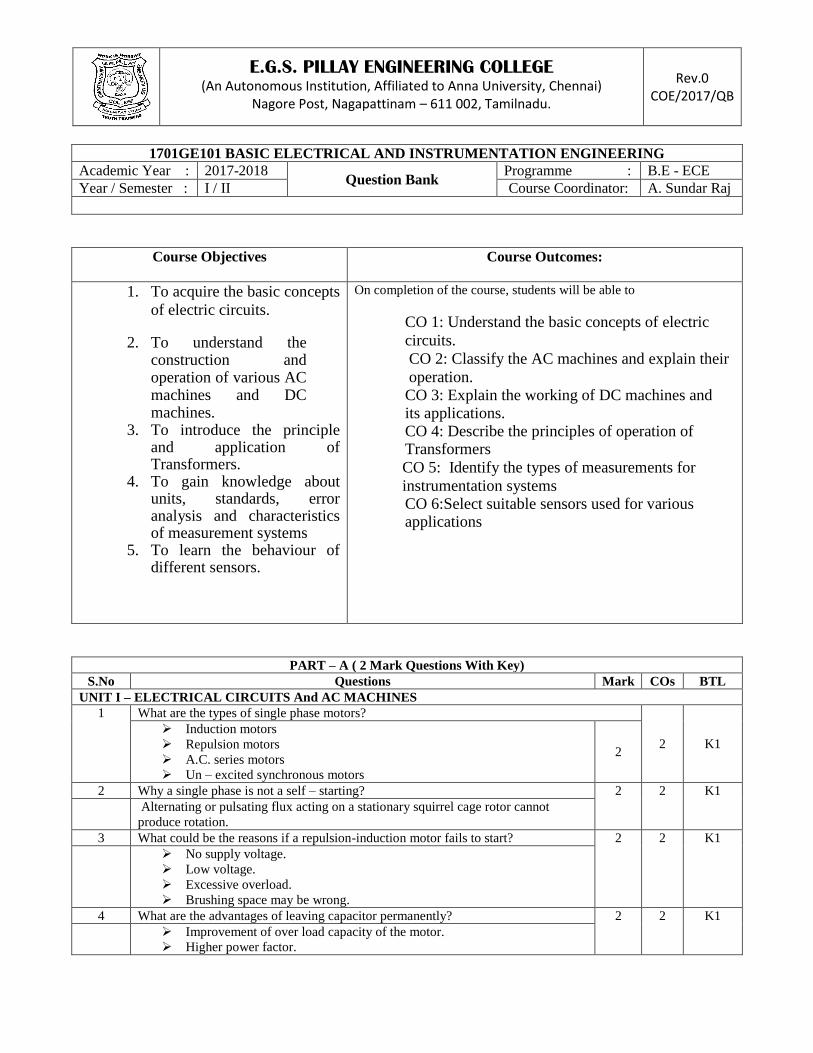
Self-excited DC generator
Series: diagram, Shunt: diagram,
4
Compound: diagram, (long, short)
Fig : long shunt Fig :short shunt
4
2
Explain the characteristics of DC generator. 12 3
K2
Open circuit characteristics
Internal and external characteristics
Internal:
3

E.G.S. PILLAY ENGINEERING COLLEGE (An Autonomous Institution, Affiliated to Anna University, Chennai)
Nagore Post, Nagapattinam – 611 002, Tamilnadu.
Rev.0 COE/2017/QB
External :
Separately excited – characteristics of occ, internal, and external
fig: 1.OCC characteristics 2.internal
3.external
2
Shunt generator - characteristics of occ, internal, and external
fig : OCC Characteristics
4

E.G.S. PILLAY ENGINEERING COLLEGE (An Autonomous Institution, Affiliated to Anna University, Chennai)
Nagore Post, Nagapattinam – 611 002, Tamilnadu.
Rev.0 COE/2017/QB
fig: external characteristics
fig : internal characteristics
Compound generator- characteristics
fig : compound characteristics
3
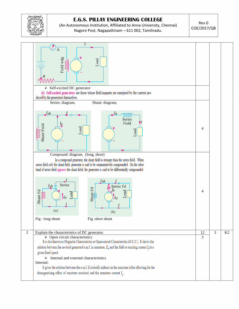
3 Extend the construction and working principle of DC motor. 12 3 K2
Principle of DC motor
4
E.G.S. PILLAY ENGINEERING COLLEGE (An Autonomous Institution, Affiliated to Anna University, Chennai)
Nagore Post, Nagapattinam – 611 002, Tamilnadu.
Rev.0 COE/2017/QB
Construction
4
Working of DC motor
4
4
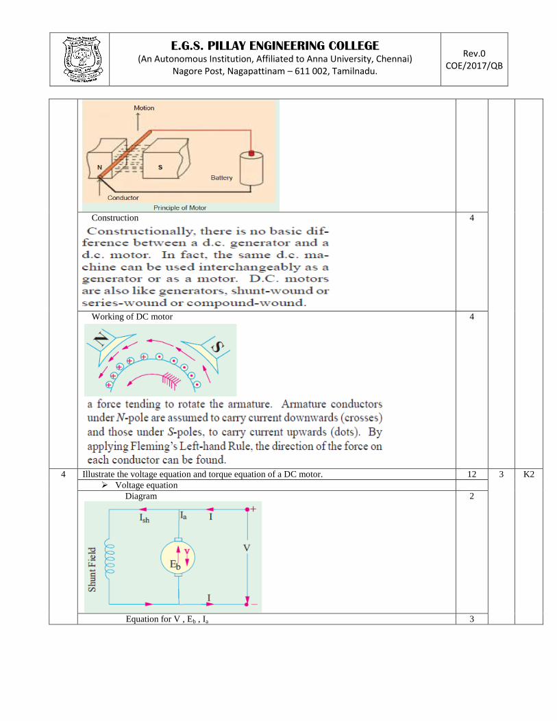
Illustrate the voltage equation and torque equation of a DC motor. 12 3
K2
Voltage equation
Diagram
2
Equation for V , Eb , Ia 3

E.G.S. PILLAY ENGINEERING COLLEGE (An Autonomous Institution, Affiliated to Anna University, Chennai)
Nagore Post, Nagapattinam – 611 002, Tamilnadu.
Rev.0 COE/2017/QB
Torque equation
Derive equation for
Work done , power developed , power in armature , armature torque
7
5 Show the construction and working principle of DC generator. 12 3 K1
Principle of DC generator
2

E.G.S. PILLAY ENGINEERING COLLEGE (An Autonomous Institution, Affiliated to Anna University, Chennai)
Nagore Post, Nagapattinam – 611 002, Tamilnadu.
Rev.0 COE/2017/QB
Construction
6
Working of DC generator
4
6
A shunt generator delivers 195A at terminal p.d. of 250V. The armature resistance and shunt field
resistance are 0.02Ω and 50Ω respectively. The iron and friction losses equal 950W. find
a) E.M.F. generated b)Cu losses c) output of the prime motor d) commercial , mechanical and
electrical coefficiencies.
12
3
K3

E.G.S. PILLAY ENGINEERING COLLEGE (An Autonomous Institution, Affiliated to Anna University, Chennai)
Nagore Post, Nagapattinam – 611 002, Tamilnadu.
Rev.0 COE/2017/QB
Given data: current, armature and shunt resistance, p.d.
SOLN:
2
3
3
4
UNIT III – SINGLE PHASE And POLYPHASE TRANSFORMERS 1 Explain a transformer test and its types. 12
4 K2
Transformer test:
Open circuit
Diagram , equation
6

E.G.S. PILLAY ENGINEERING COLLEGE (An Autonomous Institution, Affiliated to Anna University, Chennai)
Nagore Post, Nagapattinam – 611 002, Tamilnadu.
Rev.0 COE/2017/QB
Fig : open circuit
Short circuit
fig: short circuit test
6

E.G.S. PILLAY ENGINEERING COLLEGE (An Autonomous Institution, Affiliated to Anna University, Chennai)
Nagore Post, Nagapattinam – 611 002, Tamilnadu.
Rev.0 COE/2017/QB
2 Derive losses, efficiency and condition for maximum efficiency in a transformer. 12
4
K2
Losses in a transformer.
Core loss
Copper loss
4
Efficiency in a transformer
Or
4
Condition for maximum efficiency
4
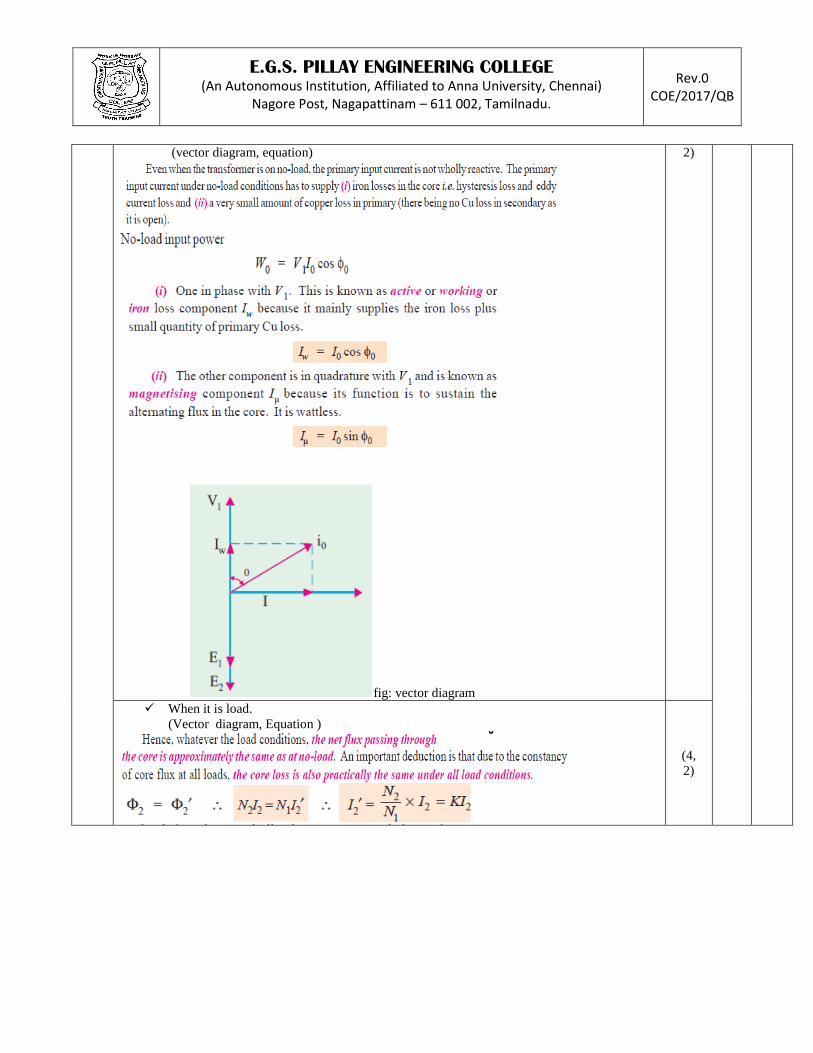
3 Explain a transformer with losses but no magnetic leakage. 12 4 K2
When it is no load. (4,
E.G.S. PILLAY ENGINEERING COLLEGE (An Autonomous Institution, Affiliated to Anna University, Chennai)
Nagore Post, Nagapattinam – 611 002, Tamilnadu.
Rev.0 COE/2017/QB
(vector diagram, equation)
fig: vector diagram
2)
When it is load.
(Vector diagram, Equation )
(4,
2)

E.G.S. PILLAY ENGINEERING COLLEGE (An Autonomous Institution, Affiliated to Anna University, Chennai)
Nagore Post, Nagapattinam – 611 002, Tamilnadu.
Rev.0 COE/2017/QB
4 i) Explain a transformer with winding resistance but no magnetic leakage. 6
4 K2
V2 , E1 equation
2
Vector diagram(non – inductive , inductive , capacitive)
4
ii) Explain a transformer with resistance and leakage reactance. 6
Equation(Z1 ,Z2, V1, E2) 3

E.G.S. PILLAY ENGINEERING COLLEGE (An Autonomous Institution, Affiliated to Anna University, Chennai)
Nagore Post, Nagapattinam – 611 002, Tamilnadu.
Rev.0 COE/2017/QB
Fig: resistance and leakage reactance
Vector diagram
3
5 1) Explain an equivalent circuit of a transformer. 6 4
K2
Circuit diagram 3

E.G.S. PILLAY ENGINEERING COLLEGE (An Autonomous Institution, Affiliated to Anna University, Chennai)
Nagore Post, Nagapattinam – 611 002, Tamilnadu.
Rev.0 COE/2017/QB
Fig: resistance and reactance leakage
Secondary circuit;
3

E.G.S. PILLAY ENGINEERING COLLEGE (An Autonomous Institution, Affiliated to Anna University, Chennai)
Nagore Post, Nagapattinam – 611 002, Tamilnadu.
Rev.0 COE/2017/QB
Fig: equivalent circuit referred as primary and secondary
4
2) A 2000-kVA, 6,600/400-V,3-phase transformer is delta connected on the voltage side and
star connected on the low voltage side. Determine its % resistance and % reactance drops,
% efficiency and % regulation on full load 0.8 p.f. leading given the following data:
S.C.test ; H.V.data : 400 V, 175A and 17kW
O.C.test ; L.V.data : 400 V, 150A and 15kW
6
K3
Given data : voltage, phase,
2
Find : %R, %X, %Reg, total losses, η
Soln:
4
6 1) A 120-kVA, 6000/400-V, Y/Y 3- ph., 50-Hz transformer has an iron loss of 1600W. The
maximum efficiency occurs at ¾ full load.
Find the efficiencies of the transformer at
i. Full load and 0.8 power factor
ii. Half load and unity power factor
iii. The maximum efficiency
8
4
K3
E.G.S. PILLAY ENGINEERING COLLEGE (An Autonomous Institution, Affiliated to Anna University, Chennai)
Nagore Post, Nagapattinam – 611 002, Tamilnadu.
Rev.0 COE/2017/QB
Find:
Full load and 0.8 power factor
Half load and unity power factor
The maximum efficiency
SOLN:
8
2
3
3
2) In a 25-kVA, 2000/200 V, single-phase transformer, the iron and full load copper losses are
350 and 400 W respectively. Calculate the efficiency at unity power factor on
i) Full load and half full -load
4
K3 Given data : voltage, losses 1
4 Calculate: full load , half full load
SOLN:
3
UNIT IV – INSTRUMENTATION SYSTEMS
1
Explain about measurement in error. 12 5
K2
Gross error
The instrument before it has reached its steady state.
Not eliminating parallax.
Mistakes in recording measured data and in calculating a derived measurand.
2

E.G.S. PILLAY ENGINEERING COLLEGE (An Autonomous Institution, Affiliated to Anna University, Chennai)
Nagore Post, Nagapattinam – 611 002, Tamilnadu.
Rev.0 COE/2017/QB
Misuse of the instrument.
System error
The instrument is not calibrated, and has an offset (i.e. its sensitivity is off, and it needs
zeroing.
Factors:
Noise from without is called environmental noise and can often be reduced by
appropriate electric and magnetic shielding.
In the first stage of an instrument’s signal conditioning amplifier. Some of this
noise comes from resistors (Johnson or thermal noise).
Slow, or long term drift in the system can destroy the certainty of static
measurements.
Drifts can cause slow changes in system sensitivity and/or zero.
2
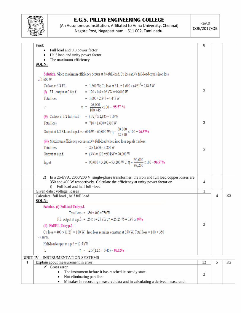
Derive the equation for Pn , dn , DN ,SN , Power measurement, SN2 , σY
2 , σV
2 ,EK.
7
E.G.S. PILLAY ENGINEERING COLLEGE (An Autonomous Institution, Affiliated to Anna University, Chennai)
Nagore Post, Nagapattinam – 611 002, Tamilnadu.
Rev.0 COE/2017/QB
Least mean square linear graph
1
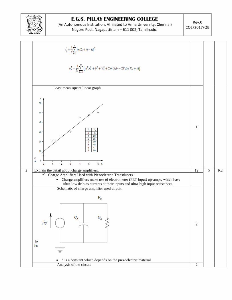
2 Explain the detail about charge amplifiers. 12 5 K2
Charge Amplifiers Used with Piezoelectric Transducers
Charge amplifiers make use of electrometer (FET input) op-amps, which have
ultra-low dc bias currents at their inputs and ultra-high input resistances.
Schematic of charge amplifier used circuit
d is a constant which depends on the piezoelectric material
2
Analysis of the circuit 2

E.G.S. PILLAY ENGINEERING COLLEGE (An Autonomous Institution, Affiliated to Anna University, Chennai)
Nagore Post, Nagapattinam – 611 002, Tamilnadu.
Rev.0 COE/2017/QB
The op-amp is assumed to have infinite gain, frequency response and input
resistance, and zero bias current, offset voltage, noise and output resistance.
Charge amplifier and crystal sensor circuit
2
DC equivalent circuit the capacitors drop out from the circuit at dc because they
carry no current. It is easy to see that the dc error in the output
2

E.G.S. PILLAY ENGINEERING COLLEGE (An Autonomous Institution, Affiliated to Anna University, Chennai)
Nagore Post, Nagapattinam – 611 002, Tamilnadu.
Rev.0 COE/2017/QB
Charge Amplifier as Integrating Coulombmeter
Coulombmeter circuit
A charge of Q1 coulombs is trapped on a capacitor, C1. The capacitor can be a real
capacitor, or the capacitance of a charged object, such as the fuselage of a
helicopter, or a human body.
2
Derive the equation
2
3 i. Explain about torque measurement. 6 5 K2
Bonded strain gauge circuit
Torque measurements on rotating shafts are made with more difficulty than are
those on stationary shafts.
Such a configuration may be shown to be insensitive to temperature changes, axial
load and bending of the shaft.
3
Derive θ , f,φ
3
E.G.S. PILLAY ENGINEERING COLLEGE (An Autonomous Institution, Affiliated to Anna University, Chennai)
Nagore Post, Nagapattinam – 611 002, Tamilnadu.
Rev.0 COE/2017/QB
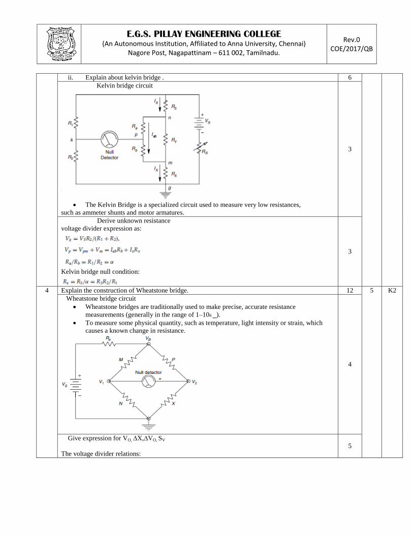
ii. Explain about kelvin bridge . 6
Kelvin bridge circuit
The Kelvin Bridge is a specialized circuit used to measure very low resistances,
such as ammeter shunts and motor armatures.
3
Derive unknown resistance
voltage divider expression as:
Kelvin bridge null condition:
3
4 Explain the construction of Wheatstone bridge. 12 5 K2
Wheatstone bridge circuit
Wheatstone bridges are traditionally used to make precise, accurate resistance
measurements (generally in the range of 1–106 _).
To measure some physical quantity, such as temperature, light intensity or strain, which
causes a known change in resistance.
4
Give expression for VO, ∆X,∆VO, SV
The voltage divider relations:
5

E.G.S. PILLAY ENGINEERING COLLEGE (An Autonomous Institution, Affiliated to Anna University, Chennai)
Nagore Post, Nagapattinam – 611 002, Tamilnadu.
Rev.0 COE/2017/QB
Wheatstone bridge output relation below:
voltage sensitivity for the bridge:
Output voltage characteristics
3
5 Explain the D’Arsonval DC voltmeter. 12 5 K2
Face view of D’Arsonval circuit
These voltmeters, also known as permanent magnet moving coil voltmeters, are the most
common design of electromechanical dc voltmeter.
2
Vertical section of D’Arsonval circuit 2
E.G.S. PILLAY ENGINEERING COLLEGE (An Autonomous Institution, Affiliated to Anna University, Chennai)
Nagore Post, Nagapattinam – 611 002, Tamilnadu.
Rev.0 COE/2017/QB
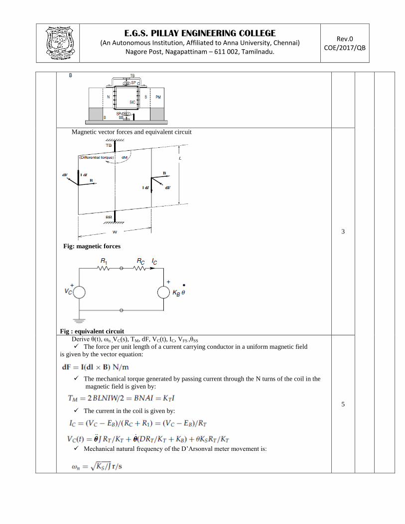
Magnetic vector forces and equivalent circuit
Fig: magnetic forces
Fig : equivalent circuit
3
Derive θ(t), ωn ,VC(s), TM, dF, VC(t), IC, VFS ,θSS
The force per unit length of a current carrying conductor in a uniform magnetic field
is given by the vector equation:
The mechanical torque generated by passing current through the N turns of the coil in the
magnetic field is given by:
The current in the coil is given by:
Mechanical natural frequency of the D’Arsonval meter movement is:
5
E.G.S. PILLAY ENGINEERING COLLEGE (An Autonomous Institution, Affiliated to Anna University, Chennai)
Nagore Post, Nagapattinam – 611 002, Tamilnadu.
Rev.0 COE/2017/QB
damping factor is given by:
The step response of the D’Arsonval meter is
The meter deflection as a function of time is
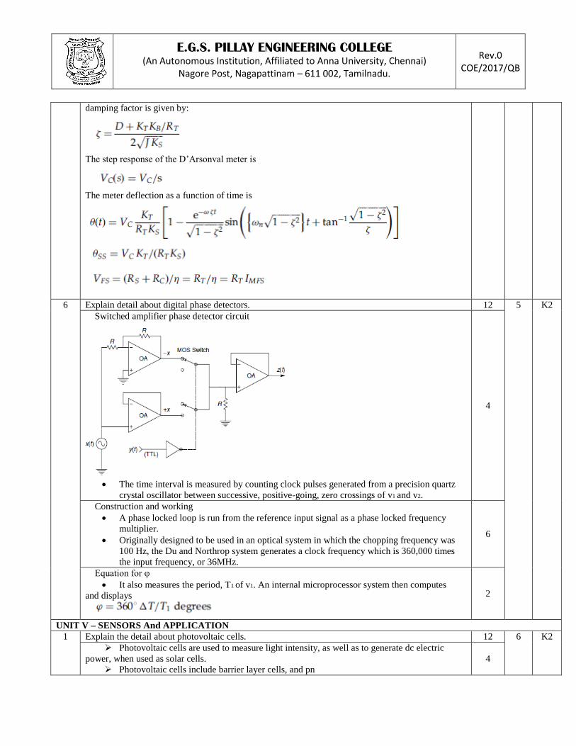
6 Explain detail about digital phase detectors. 12 5 K2
Switched amplifier phase detector circuit
The time interval is measured by counting clock pulses generated from a precision quartz
crystal oscillator between successive, positive-going, zero crossings of v1 and v2.
4
Construction and working
A phase locked loop is run from the reference input signal as a phase locked frequency
multiplier.
Originally designed to be used in an optical system in which the chopping frequency was
100 Hz, the Du and Northrop system generates a clock frequency which is 360,000 times
the input frequency, or 36MHz.
6
Equation for φ
It also measures the period, T1 of v1. An internal microprocessor system then computes
and displays
2
UNIT V – SENSORS And APPLICATION 1 Explain the detail about photovoltaic cells. 12 6 K2
Photovoltaic cells are used to measure light intensity, as well as to generate dc electric
power, when used as solar cells.
Photovoltaic cells include barrier layer cells, and pn
4

E.G.S. PILLAY ENGINEERING COLLEGE (An Autonomous Institution, Affiliated to Anna University, Chennai)
Nagore Post, Nagapattinam – 611 002, Tamilnadu.
Rev.0 COE/2017/QB
junction photodiodes.
Give the equation for, EOC, iD, Vo: open circuit EMF, given by the relation
Current curve is given by:
The op-amp output is thus given approximately by:
Characteristics curve: for current VS voltages
for open circuit voltage VS short circuit current
4
OP-amp trans resistor circuit
The thickness of the n region must be such that the electrons generated in the region can
diffuse to the junction before they, too, recombine.
This requirement implies a match between the hole diffusion length, Lp, the thickness of the
n region and the optical penetration depth in the surface p layer.
It is also desirable in solar cell design to have a large contact potential in
order to realize a large photovoltage.
4

E.G.S. PILLAY ENGINEERING COLLEGE (An Autonomous Institution, Affiliated to Anna University, Chennai)
Nagore Post, Nagapattinam – 611 002, Tamilnadu.
Rev.0 COE/2017/QB
2
Explain the construction and working principles of piezoelectric transducers. 12 6
K2
Piezoelectric transducers: Piezoelectric materials, when mechanically strained in a preferred manner, generate an
open circuit EMF.
All piezoelectric materials have a Curie temperature, above which piezoelectric activity
ceases to exist.
Give the equation for CX ,Y ,Q ,EO , ieq , Vo / F :
The capacitance of the transducer is approximately:
The piezo material is assumed to have a Young’s modulus, Y.
The net charge displacement for the transducer is given by:
open circuit voltage across the transducer as:
current is the rate of flow of charge, the equivalent current source is:
Open circuit voltage across the transducer is given by the transfer function:
4
Piezoelectric transducers diagram 2

E.G.S. PILLAY ENGINEERING COLLEGE (An Autonomous Institution, Affiliated to Anna University, Chennai)
Nagore Post, Nagapattinam – 611 002, Tamilnadu.
Rev.0 COE/2017/QB
A rectangular crystal block, with metallic electrodes vapor deposited on its top and
bottom surfaces. The transducer has thickness t and top area A.
Equivalent circuit to applied force
To improve and control low frequency response of a piezoelectric transducer system,
We wish to connect the transducer to an amplifier with an ultra high input impedance.
Such amplifiers are called electrometer amplifiers.
2
Electrometer OP-amp
Here, we neglect any series resistance between the transducer and the op-amp’s summing
junction.
If the op-amp is considered to be ideal, it is easy to see that the transducer current, Fd, only
flows through the amplifier’s feedback conductance.
2
Equivalent circuit of piezoelectric transducers. 2

E.G.S. PILLAY ENGINEERING COLLEGE (An Autonomous Institution, Affiliated to Anna University, Chennai)
Nagore Post, Nagapattinam – 611 002, Tamilnadu.
Rev.0 COE/2017/QB
3 Explain the construction of hall sensors effect. 12 6 K2
Schematic of hall sensors effect
Hall effect sensors, unlike Faraday effect devices, use no moving, conductive fluid.
Instead, the majority charge carriers (electrons or holes) have some average drift velocity
as they traverse a bar of doped semiconductor.
4
Construction
In the case of the Faraday transducer, the magnetic field B, the drift velocity v and the
voltage measuring axis are ideally orthogonal.
Each hole or electron with velocity v in the semiconductor.
2
Give the equation for F , -qEZ, Vn ,EZ
Lorentz force given by the vector equation:
Lorentz force is balanced by the electrostatic force on the electron due to the electric
Field,
The average drift velocity of electrons is given by:
2
Derive the equation for VH , VH
The Hall voltage developed across the two metallized faces of the bar is just VH =Ez 2aV.
4

E.G.S. PILLAY ENGINEERING COLLEGE (An Autonomous Institution, Affiliated to Anna University, Chennai)
Nagore Post, Nagapattinam – 611 002, Tamilnadu.
Rev.0 COE/2017/QB
The phase between the I and V sinusoids is θ.
It is easy to show that the dc component of the Hall voltage is proportional to the average power in
the load; that is, it is given by:
4 Define LVDT and explain the construction of LVDT 12 6 K2
LVDT definition:
LVDTs are used to measure linear mechanical displacement or position in control systems
and in precision manufacturing gauging, and can be used indirectly to measure force,
pressure, acceleration, etc., or any quantity that can cause a linear displacement.
2
Longitudinal section of LVDT
Central excitation coil, two, symmetrically located pick-off coils
and the hollow, cylindrical core tube through which slides the high permeability
magnetic core.
4
LVDT schematic
The two series pick-off coils have opposite dot polarity, so that, when the moveable
magnetic core is at magnetic center (x=0), the induced EMFs in each coil sum to zero at the
output.
4
Characteristics curve:
Output voltage VS linear core displacement
2
5 Explain the detail about variable capacitance sensors. 12 6 K2
Give the equation for C 2

E.G.S. PILLAY ENGINEERING COLLEGE (An Autonomous Institution, Affiliated to Anna University, Chennai)
Nagore Post, Nagapattinam – 611 002, Tamilnadu.
Rev.0 COE/2017/QB
The capacitance between two parallel, conducting plates, each of area A, separated by
a dielectric of thickness d is given by (neglecting fringing effects):
Differential pressure sensors diagram
A capacitive pressure transducer in which a diaphragm deflects as the result of the pressure
differential across it.
Dielectric constants also change with temperature, so a null transducer can be used in a
bridge circuit to obtain temperature compensation.
Dranetz, Howatt and Crownover, cited by Lion, developed a titanate ceramic called
Thermacon, in which the dielectric constant decreased linearly over the temperature range
of - 40 to +160 0C.
5
Derive the equation for
VO / VS (s) , VO(t)
5
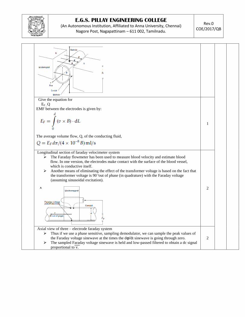
6 Explain the construction of faraday effect flowmeter. 12 6 K2
Schematic diagram of Faraday effect liquid velocimeter
Two electrodes on opposite sides of the circular cross-section pipe make ohmic contact
with the conductive fluid in the pipe moving with average velocity, v.
A uniform magnetic field of B Tessla is perpendicular to the v vector and the L vector
between the centers of the electrodes.
2
E.G.S. PILLAY ENGINEERING COLLEGE (An Autonomous Institution, Affiliated to Anna University, Chennai)
Nagore Post, Nagapattinam – 611 002, Tamilnadu.
Rev.0 COE/2017/QB
Give the equation for
EF , Q
EMF between the electrodes is given by:
The average volume flow, Q, of the conducting fluid,
1
Longitudinal section of faraday velocimeter system
The Faraday flowmeter has been used to measure blood velocity and estimate blood
flow. In one version, the electrodes make contact with the surface of the blood vessel,
which is conductive itself.
Another means of eliminating the effect of the transformer voltage is based on the fact that
the transformer voltage is 90 0out of phase (in quadrature) with the Faraday voltage
(assuming sinusoidal excitation).
2
Axial view of three – electrode faraday system
Thus if we use a phase sensitive, sampling demodulator, we can sample the peak values of
the Faraday voltage sinewave at the times the dφ/dt sinewave is going through zero.
The sampled Faraday voltage sinewave is held and low-passed filtered to obtain a dc signal
proportional to v.
2

E.G.S. PILLAY ENGINEERING COLLEGE (An Autonomous Institution, Affiliated to Anna University, Chennai)
Nagore Post, Nagapattinam – 611 002, Tamilnadu.
Rev.0 COE/2017/QB
System of faraday liquid velocity sensor
One detects the desired Faraday voltage and the other, using a quadrature reference, detects
the unwanted transformer voltage.
A dc signal, VT, proportional to the transformer voltage, acts through an analog multiplier
to vary the level of a quadrature signal, VQF.
4
Give VOD equation
The quadrature detector loop acts to reduce the amount of transformer voltage
contaminating
the desired VF signal,
1
Note : 6 Questions with answer key must be prepared in each unit and maximum two sub divisions are allowed.
PART – C (20 Mark Questions with Key)
S.No Questions Mark COs BTL
UNIT I – ELECTRICAL CIRCUITS And AC MACHINES 1 Explain the construction and working principles of alternators. 20 2
K2
Principle
4

E.G.S. PILLAY ENGINEERING COLLEGE (An Autonomous Institution, Affiliated to Anna University, Chennai)
Nagore Post, Nagapattinam – 611 002, Tamilnadu.
Rev.0 COE/2017/QB
Alternator diagram
5
Construction (stator , rotor)
STATOR:
ROTOR:
6

E.G.S. PILLAY ENGINEERING COLLEGE (An Autonomous Institution, Affiliated to Anna University, Chennai)
Nagore Post, Nagapattinam – 611 002, Tamilnadu.
Rev.0 COE/2017/QB
Advantages.
5
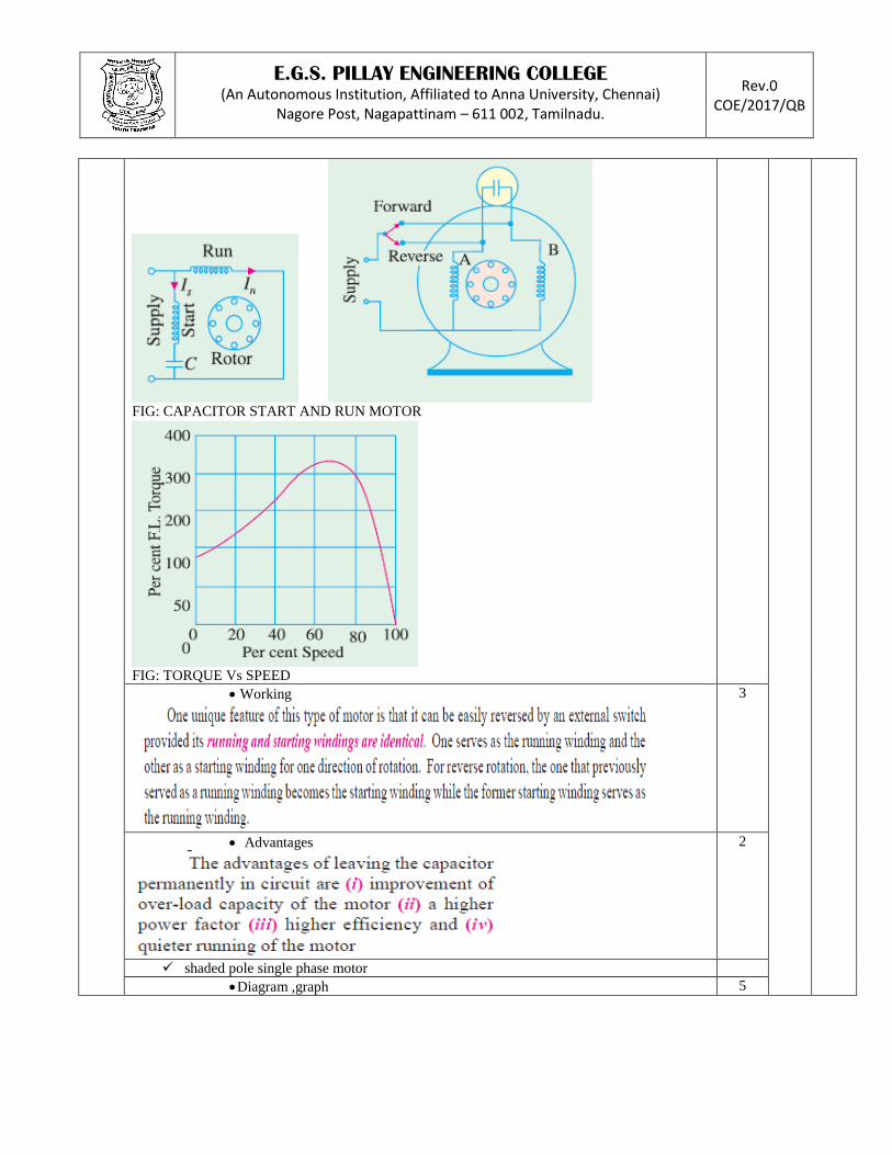
2 Explain a capacitor start – and – run motor and shaded pole single phase motor. 20 2
K2 capacitor start – and – run motor
Diagram,graph 5
E.G.S. PILLAY ENGINEERING COLLEGE (An Autonomous Institution, Affiliated to Anna University, Chennai)
Nagore Post, Nagapattinam – 611 002, Tamilnadu.
Rev.0 COE/2017/QB
FIG: CAPACITOR START AND RUN MOTOR
FIG: TORQUE Vs SPEED
Working
3
Advantages
2
shaded pole single phase motor
Diagram ,graph 5

E.G.S. PILLAY ENGINEERING COLLEGE (An Autonomous Institution, Affiliated to Anna University, Chennai)
Nagore Post, Nagapattinam – 611 002, Tamilnadu.
Rev.0 COE/2017/QB
FIG:SHADED POLE DIAGRAM
FIG:TORQUE Vs SPEED
Working
3
Disadvantages
2
E.G.S. PILLAY ENGINEERING COLLEGE (An Autonomous Institution, Affiliated to Anna University, Chennai)
Nagore Post, Nagapattinam – 611 002, Tamilnadu.
Rev.0 COE/2017/QB
UNIT II - DC MACHINES
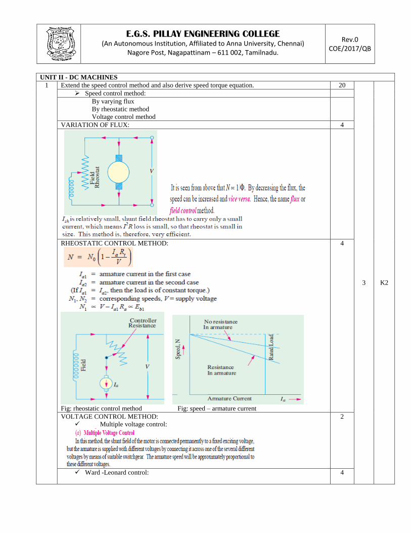
1 Extend the speed control method and also derive speed torque equation. 20
3 K2
Speed control method:
By varying flux
By rheostatic method
Voltage control method
VARIATION OF FLUX: 4
RHEOSTATIC CONTROL METHOD:
Fig: rheostatic control method Fig: speed – armature current
4
VOLTAGE CONTROL METHOD:
Multiple voltage control:
2
Ward -Leonard control:
4

E.G.S. PILLAY ENGINEERING COLLEGE (An Autonomous Institution, Affiliated to Anna University, Chennai)
Nagore Post, Nagapattinam – 611 002, Tamilnadu.
Rev.0 COE/2017/QB
Disadvantage:
Speed torque equation : Eb , N
6
2 Explain the characteristics of DC motor. 20
Shunt motor
Speed-current
7 3 K2
E.G.S. PILLAY ENGINEERING COLLEGE (An Autonomous Institution, Affiliated to Anna University, Chennai)
Nagore Post, Nagapattinam – 611 002, Tamilnadu.
Rev.0 COE/2017/QB
Speed-current
Torque-armature current
Series motor 7

E.G.S. PILLAY ENGINEERING COLLEGE (An Autonomous Institution, Affiliated to Anna University, Chennai)
Nagore Post, Nagapattinam – 611 002, Tamilnadu.
Rev.0 COE/2017/QB
FIG: TORQUE – ARMATURE CURRENT
FIG:SPEED – ARMATURE CURRENT
FIG: SPEED- TORQUE
Compound motors
1. Cumulative compound motor:
6

E.G.S. PILLAY ENGINEERING COLLEGE (An Autonomous Institution, Affiliated to Anna University, Chennai)
Nagore Post, Nagapattinam – 611 002, Tamilnadu.
Rev.0 COE/2017/QB
2. Differential compound motor:
Fig: speed – current

E.G.S. PILLAY ENGINEERING COLLEGE (An Autonomous Institution, Affiliated to Anna University, Chennai)
Nagore Post, Nagapattinam – 611 002, Tamilnadu.
Rev.0 COE/2017/QB
Fig : torque - current
UNIT III - SINGLE PHASE And POLYPHASE TRANSFORMERS 1 Explain construction and working principles of transformer and e.m.f equation of a transformer. 20
4 K2
Transformer:
Transformer types
Core type
Shell type
2
Construction
Fig : principle of transformer
Fig : core type
6

E.G.S. PILLAY ENGINEERING COLLEGE (An Autonomous Institution, Affiliated to Anna University, Chennai)
Nagore Post, Nagapattinam – 611 002, Tamilnadu.
Rev.0 COE/2017/QB
Fig : shell type
Working
CORE TYPE:
SHELL TYPE:
Advantages of shell type:
6
E.m.f equation of a transformer
6

E.G.S. PILLAY ENGINEERING COLLEGE (An Autonomous Institution, Affiliated to Anna University, Chennai)
Nagore Post, Nagapattinam – 611 002, Tamilnadu.
Rev.0 COE/2017/QB
2 Analysis the parallel operation of single phase transformers. 20 4 K4
Equivalent circuit
2
Conditions 3

E.G.S. PILLAY ENGINEERING COLLEGE (An Autonomous Institution, Affiliated to Anna University, Chennai)
Nagore Post, Nagapattinam – 611 002, Tamilnadu.
Rev.0 COE/2017/QB
2 cases
Case 1: ideal case
(equation, diagram)
5
Case 2:equal voltage ratios
(equation, diagram)
10

E.G.S. PILLAY ENGINEERING COLLEGE (An Autonomous Institution, Affiliated to Anna University, Chennai)
Nagore Post, Nagapattinam – 611 002, Tamilnadu.
Rev.0 COE/2017/QB
UNIT IV – INSTRUMENTATION SYSTEMS
1 Explain briefly about measurement system architecture. 20 5 K2
Block diagram of measurement system
Measurement systems are traditionally used to measure physical and
electrical quantities, such as mass, temperature, pressure, capacitance and
voltage.
The quantity under measurement (QUM) is converted to a useful form, such
as a voltage, current or physical displacement by an input transducer or
sensor.
6

E.G.S. PILLAY ENGINEERING COLLEGE (An Autonomous Institution, Affiliated to Anna University, Chennai)
Nagore Post, Nagapattinam – 611 002, Tamilnadu.
Rev.0 COE/2017/QB
Major sources:
1. Noise sensed along with the QUM (environmental noise)
2. Noise associated with the electronic signal conditioning system (referred to its
input)
3. Equivalent noise generated in the analog to digital conversion process (quantization
noise)
Sensor dynamics Relating VX and X
5

E.G.S. PILLAY ENGINEERING COLLEGE (An Autonomous Institution, Affiliated to Anna University, Chennai)
Nagore Post, Nagapattinam – 611 002, Tamilnadu.
Rev.0 COE/2017/QB
Transfer function, step response of under damped, over damped (low pass and
band pass), critically damped
5

E.G.S. PILLAY ENGINEERING COLLEGE (An Autonomous Institution, Affiliated to Anna University, Chennai)
Nagore Post, Nagapattinam – 611 002, Tamilnadu.
Rev.0 COE/2017/QB
Overview of signal condition
Sometimes the measurement process or the sensor introduces a nonlinear distortion of the
QUM (as in the case of hot wire anemometers) which must be linearized.
Such amplification and filtering is usually performed by a low noise instrumentation
amplifier, followed by op-amp active filters.
This low-pass filtering before sampling is called anti-aliasing filtering and is necessary
for accurate digital signal processing.
4
2 Analysis the performance of Anderson constant current loop 20 5 K4
Advantage of Anderson loop system
Larger and inherently linear outputs that are individually available from each
element in a sensor (e.g. a bridge circuit)
Power dissipation of the sensor is lowered—beneficial in portable and temperature
sensitive applications
Fewer, smaller and less expensive lead wires are required in tight installations
Quieter engineering unit readouts are available
2
Single loop Anderson loop system circuit
A remote sensor transduces the quantity under measurement (QUM) (e.g., temperature)
into a change of resistance, ∆R.
4
Analysis of circuit
DDS output is: 4

E.G.S. PILLAY ENGINEERING COLLEGE (An Autonomous Institution, Affiliated to Anna University, Chennai)
Nagore Post, Nagapattinam – 611 002, Tamilnadu.
Rev.0 COE/2017/QB
Rref is made equal to R, the output is linearly proportional to ∆R:
Expression for the output voltage of the DDS can be written:
Applied to a capacitive sensor
\
The magnitude of Vo is proportional to _C and calibration depends on knowing
Is, its frequency,ω and Co.
2
Anderson loop applied to a group of sensor Anderson loop system applied to a remote circuit
The QUM causes the resistance of the upper sensor to increase the same amount
that the resistance of the lower sensor decreases.
The DDS output voltage is:
2

E.G.S. PILLAY ENGINEERING COLLEGE (An Autonomous Institution, Affiliated to Anna University, Chennai)
Nagore Post, Nagapattinam – 611 002, Tamilnadu.
Rev.0 COE/2017/QB
Stiff current sources
The dc CM voltages are:
2
Schematic of andersonizing 4-arm Wheatstone bridge
The bridge output can easily be found using voltage divider
relations:
4
E.G.S. PILLAY ENGINEERING COLLEGE (An Autonomous Institution, Affiliated to Anna University, Chennai)
Nagore Post, Nagapattinam – 611 002, Tamilnadu.
Rev.0 COE/2017/QB
UNIT V – SENSORS And APPLICATION
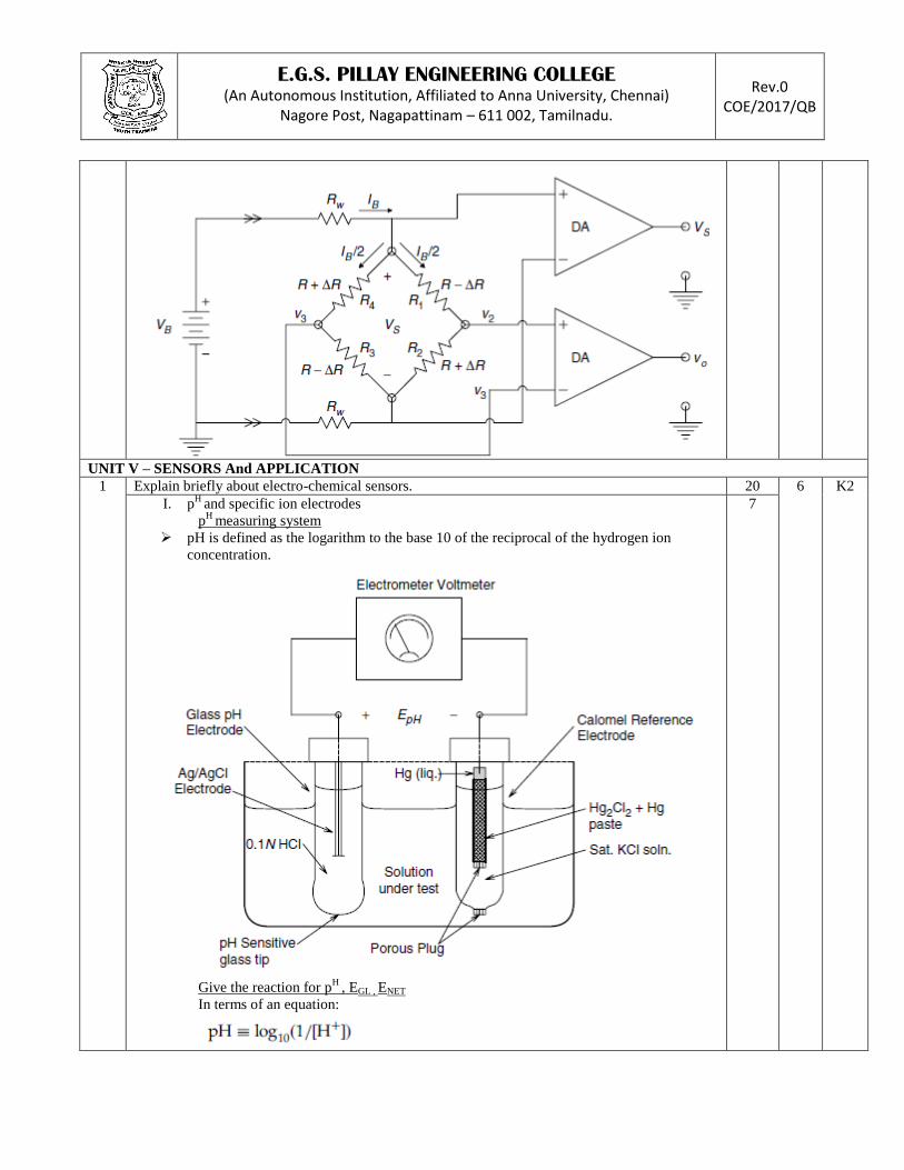
1 Explain briefly about electro-chemical sensors. 20 6 K2
I. pH
and specific ion electrodes
pH
measuring system
pH is defined as the logarithm to the base 10 of the reciprocal of the hydrogen ion
concentration.
Give the reaction for p
H , EGL , ENET
In terms of an equation:
7

E.G.S. PILLAY ENGINEERING COLLEGE (An Autonomous Institution, Affiliated to Anna University, Chennai)
Nagore Post, Nagapattinam – 611 002, Tamilnadu.
Rev.0 COE/2017/QB
The total pH cell’s EMF is given by summing the half-cell EMFs:
The pH of the Severinghaus cell may be shown to be equal to:
II. Polargraphic electrodes
Polarographic electrodes differ from pH and ion specific cells in that a
polarographic cell is run at a constant potential in order to force two electrochemical
reactions to take place.
Cross section through Clark
Schematic
A current flows, which is described by the relation:
8

E.G.S. PILLAY ENGINEERING COLLEGE (An Autonomous Institution, Affiliated to Anna University, Chennai)
Nagore Post, Nagapattinam – 611 002, Tamilnadu.
Rev.0 COE/2017/QB
III. Fuel cell electrodes
A fuel cell is a battery (cell) in which the chemical reactions producing the EMF
and output current occur at one or both half-cell electrodes and consume two or more
reactants, which are broken down to reaction products.
Glucose oxidase catalyzes the oxidation of glucose to gluconic acid and H2O2. Catalase
catalyzes the breakdown of H2O2 according to the reaction:
5
2 Extend the equation for pyro electric sensor and its construction. 20 6 K2
Pyro electric sensor:
Pyroelectric materials (PyMs) are crystalline or polymer substances that generate
internal,electrical charge transfer, in response to internal heating, caused by the
absorption of long wave, infrared radiation (LIR).
Analysis the equation for pyro- electric
Find current, voltage, thermal time constant, ideal current source, output voltage.
Heat balance differential equation for the PyM sensor as:
Laplace transformed and written as a transfer function:
The short circuit current is given by equation
CT is the sensor’s thermal time constant, which is material and dimensionally dependent.
Pio is assumed constant and is given by:
The output voltage of the op-amp is given by (note the direction of ip):
Computer subtracts Vopk from Vocal to form _Vo:
The system response to a step input of LIR irradiative power, Pi, is:
10

E.G.S. PILLAY ENGINEERING COLLEGE (An Autonomous Institution, Affiliated to Anna University, Chennai)
Nagore Post, Nagapattinam – 611 002, Tamilnadu.
Rev.0 COE/2017/QB
Schematic of electrometer charge amplifier
4
Equivalent circuit of PyM sensor
2
Applications of PyM
Sensors and burglar alarms,
Automatic patio light switches,
Sensors in various LIR spectrometers used in analytical chemistry.
They are also used in the line of ThermoscanTM
fever thermometers.
Non-invasively measure the temperature of the eardrum
4
Note : 2 Questions with answer key must be prepared in each unit and maximum two sub divisions are allowed.