Embed Size (px)
Citation preview

REPORT SAMSO-TR-76-191
BEST AVAILABLE COPY
Effects of Thermal-Mechanical
Processing on the MicroyieldStrength of Invar
Materials Sciences LaboratoryLaboratory Operations
The Aerospace CorporationEl Segundo, Calif. 90245
12 August 1976
Interim Report ,
APPROVED FOR PUBLIC RELEASE;DISTRIBUTION UNLIMITED
Prepared forSPACE AND MISSILE SYSTEMS ORGANIZATION
AIR FORCE SYSTEMS COMMANDLos Angeles Air Force Station
P.O. Box 92960, Worldway Postal CenterLos Angeles. Calif. 90009
BEST AVAILABLE Copy

This report wa# submitted by The Aerospace Corporation, El Segundo,
CA 90245, under Contract F04701-75-C-0076 with the Space and Missile
Systems Organization, Deputy for Advanced Space Programs, P.O.
Box 92960, Worldway Postal Center, Los Angeles, CA 90009. It was re-
viewed and approved for The Aerospace Corporation by W. C. Riley,
Director, Materials Sciences Laboratory. Lt. Ronald C. Lawson,
SAMSO/YAPT, was the project officer.
This report has been reviewed by the Information Office (01) and isreleasable to the National Technical Information Service (NTIS). At NTIS,
it will be available to the general .piiblic, including foreign nations.
This technical report has been reviewed and is approved for publication.
Publication of this report does not constitute Air Force approval of the
report's findings or conclusions. It is published only for the exchange and
stimulation of ideas.
FOR THE COMMANDER
Ronald C. Lawson1st Lieutenant, USAFTechnology Plans DivisionDeputy for Advanced Space Programs
.............
. . . .. ................
. . . . .. .......
L SEUIYcýSn~INO THIS PAGE (l41Wh Data. Entered.)
_R4IEPOR~U ETTO P EBEFORE COMPLETING FORM
SAS-2 OVT AC CESr -2:U.1?1 914*Abý '-
L EFFECTS OF TH-ERMAL...MECHANICALInei"PROGESSING115N THE MITR~OYIELD ______ __
-§TRE NOTPII OF IN VAR -:' 6.___oREORWAE
E. C. S kius D. L./Dull/U. Olt ' 6 FO47 St -75 -C '76
BPERFORMING ORGANIZATION NAMa AND .DDRESS 10. PROGRAM ELEMENT, PROJECT. TASK
The Aerospace CorporationEl Segundo, Calif. 90245
II O-NTROLLING OFFICE N AME AND ADDRESS M
Spacte and Missile Systeil-ib OC-gani:zation uuf 076A
Air I orce Systems C3rnrrandLos Angeles, Calif. 90009
Is. MONITORING AGENCY NAME a ADDRESS(lf dllteeant from Conrot'lling Office) IS. SECURITYCAS o this report)
Unclassified
le. ECL ASSI F1CATION DOcWNGRADINGSCHEDULE
16. 0,STRIBUTCON STATZMENT(otiR.r)
Approved for public relcase; dlistribution unlimited
* 17, aisTnrt.UTION STATEMENT (of the &&#tract entered lIn Black 20, if different from Report)
IS. SUPPLEMENTARY' NOTES*
Ito. KEY WOROS (Cr'nfinue onl reverse side it necoe..iry and Identlity by block number)
Microyield Strength4 The rmai-M*echanical Proc essing
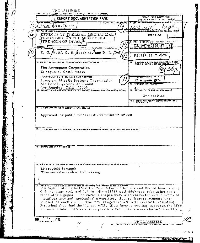
20. A81STRACT (Continue o,) reverse aide It nec erT arid identify by block number)Microyiebfi strengths (MYS) v 're determined for 20- and 40-mnil Invar sheet,0. 5-in. -diam rod, and 0. 5-in. -rdivn- (1/32 wall thickness) tube using resis-tance strain gages. The various shapes were also characterized in term-s ofrnetallography and yt~echanical properties. Several heat treatm-ents werestudied for each shapev. Tile M'yS ranged from 9 to 31 ksi (62 to ý1 4 MPa).Siretched sheet had the highecst N4YS. Slow fiirnr ., coolhiig ititi-.eas& th MYu, .:u(I awl Lulj. itress versus plastic strain curves were characteriz~ed b-y
DDI"""' N 1413L F.-V UNCLASSIFIED)
( LIECLJRITY CLASZIICATION OF THIS PAGE (When VAt. Entoredý

UNCLASSIFIEDSECURITY CLASSIFICATION Or THIS PAOE(Whan Data EnteBoW
IS. KEY WORDS (Continued)
20. ABSTRACT (Continued)
the logarithmic relationship Two sets of K and n (below and abovethe MYS) were determined for sheet with 2% stretching.
UNCLASSIFIED
SECURITY CLASSIFICATION OF THIS PAOrE(Wh'hn Data Entered)
PREFACE
This report is the first of a series describing the results from a
research program on the dimensional stability of Invar. Subsequent reports
will sumnmarize the results of dimensional changes under zero stress condi-
tions, microcreep, and the thermal expansion coefficient in the temperature
range 25 to 150'C.
Contributors to the research program since its initiation in July 1971
include the following:
T. J. Bertone Metallography
D. L. Dull Microyield Strength
SS.A. Eselun Thermal Expansion
A. N. Ewing Thermal ExpansionL. F. Goldstein Optics Consultant
K. T. Kamber Technical Consultant
E. G. Kendall Administrative Support
L. King Data !leduction
M. Lachuk Thermal ExpansionB. Larsen Data Reduction
. W. M. Leveroni Program Office Monitor
L. Raymond Administrative Support
J. H. Richardson Laser Interferornetry
H. Smallen Program Administration
3. K. Stanley Initial Technical DirectorC C. S. Susskind Strain Gage Techniques
1'. S. Thompson Thermal Expansion
E. G, Wolff Technical Director afterOctober 1973.
-1-
' •
' -: •-- - -• --- . . . . " • '"-• • •qf 't • * •. .• • , -• . ..--- • . .. ,. 4
S. . . . . -. .. . .'% . 4 ,_- - ¢
FNEý. 0)!1r, PA7k& AANK,140T f- L1141D
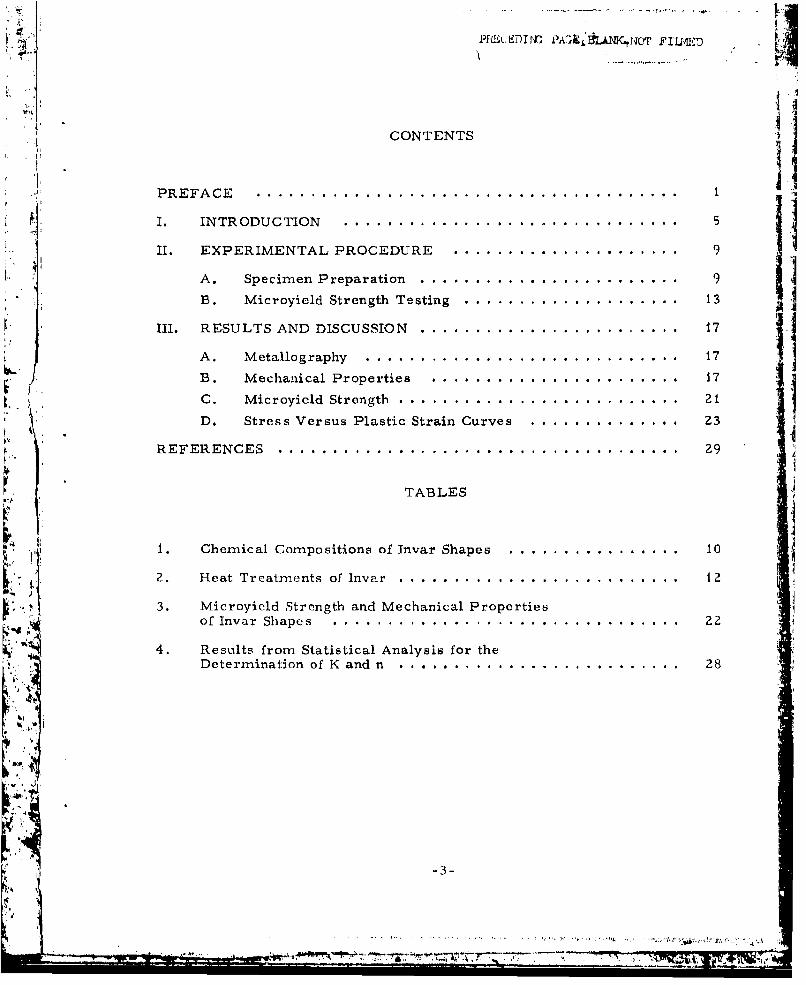
CONTENTS
PREFACE .......................................
I. INTRODUCTION ............................... 5
II. EXPERIMENTAL PROCEDURE ..................... 9
A. Specimen Preparation ........................ 9B. Microyield Strength Testing .................... 13
III. RESULTS AND DISCUSSION ........................ 17
A. M etailography ............................. 17
B. Mechanical Properties ....................... 17
C. Microyield Strength .......................... 21D. Stress Versus Plastic Strain Curves .............. 23
REFERENCES ..................................... 29
TABLES
1. Chemical Compositions of Invar Shapes ................ 10
2. Heat Treatments of Inv r.r .......................... iz
3. Microyield Strength and Mechanical Propertiesof Invar Shapes . ................................ 22
4. Results from Statistical Analysis for theDetermination of K and n ........ ... .......................... 28
-3-
. ."' .... r , 0 2f...IIIIIII-
-

FIGURES
1. Specimen configurations used for Invar program..........1
2. Experimental test setup for MYS determination............14
3. Plot of cumulative plastic rnicrostrain versus cumulativetime at stress. (The applied stress was 22. 1 ksi,i. e,, the MYS.) .. .. .. ...... ...... ...... .... ...... ...... ......... 15
4. Optical micrograph of as-received Invar 20-mil;heet in longitudinal direction. .. .. .... ...... .... ...... .............. 18
5. Optical micrograph of Invar 40-mui sheet (40-2 heattreatment) in longitudinal direction. .. .. .. .... ...... .... ......... 18
6. Optical micrograph of Invar rod (R.-i heat treatment)in radial direction .. .. .. .... .... ...... ...... ...... .... ............
7. Optical micrograph of Invar tube (T- I heat treatment)in radial direction... .. .. .. .... ..................................................... 19
8. SEM micrograph of Invar 40-mul sheet (40- 1 heatt reatmnent) in longitudinal dire ction showing squareareas Aand Bused for EDAX .. .. .. ...... .... ...... ...... ....... 20
9. EDAX of. Invar 40 -mil sheet in square areas A and Bshown in Fig. 8. (The two highest intensities cor-respond to Fe and Ni, respectively,)...... .... ...... ...... ....... 20
I 0. Stress-plastic strain curve of a 20-mil sheet. .. .... ...... ....... 24
I t. Stress-plastic strain curves of 40-mul sheet 2
12. Log-log plot of stress-plastic strain curve of 40-mul
sheet (40-2-L). .. .. .... ...... .... ...... ...... ...... .... ......... 27
-4- 1

I. INTRODUCTION
Dimensional stability is defined as the ability of a material to resist
permanent dimensional changes caused by externally applied stresses,
temperature excursions, redistribution of residual stresses, or metallurgical
phase instability. Dimensional changes in materials caused by externally
applied stress are important to the designer of precision instruments. Most
materinis plastically deform at a stress significantly lower than the conven-
ti-Lial 0. 2% offset yield strength, i. e. , stress required to produce Z000
microstrain (4c) of plastic strain. The conventional yield strength is of
little use to the designer who must know the stress that produces a plastic
strain of i L. For a precise method for measuring the stress to produce
such an'11 plastic strains, precision strain-gage techniques are used. This
' method involves loading and unloading a material to successively higher
stresses and measuring the residual plastic strain between each loading step.
The microyield strength (MYS) is defined as the stress required to produce -1plastic strain of I 4e.
T1 ie purpose of this Ltudy was to determine how thermal.- mechanical
processing could be used to increase the MYS of Invar sheet, rod, and tube.
A high MYS is desired to minimize dimensional changes due to microcreep
during short-term leading. The thermal- mechanical treatments include
austenitizing followed by water quenching, long-time thermal treatment at
low and high temperatures followed by air or furnace cooling, and stretching,
i.e., cold-working.
In 1896, Giullaurne discovered that iron with 36% nickel exhibited
an unusually low thermal expansion coefficient. Invar, the name given to
this alloy, is used today for optical components, optical component housing,microwave Filters, intercornectors for solar cells, cryogenic piping, wave-
guides, temperature regulators, and TV camera supports for space probes.
Compared to low-thermal expansion ceramirs or composites, Invar has better
machinability, higher thermal and electrical conductivity, higher thermal
-*--

* shock resistance, better magnetic properties, better vacuum stab';ity, and2
more moderate cost. The principal disadvantages are the relatively high
density and the limited temiperature range for a low thermal expansion
coefficient and dimensional instability, which are dependent on thermal-
"mechanical processing and chemical composition.
"There have been relatively few investigations reported to date on the
MYS of Invar and its alloys. Hordon and Weihrauch3 studied Invar "36"
(0. 12% C, 1% Mn, and 0.35% Si) using capacitance strain gages. The Invar
was solution-treated at 830*C, quenched, rough-machiied, stress-relieved
at 650°C, air cooled, finished-machined, and stabilized at 93°C for 48 hr
with air cooling. The elastic limit was defined as the stress at which a
plastic strain was first detected. Loads were applied in increments ofilk , 400 psi .-it rates of 20 ksi/min with immediate unloading when the stress was
" . reached. They reported the elastic li-nit to be 26. 4 ksi. Extensive MYSstudies of Ni-Span-C (42% Ni, 5-6% Cr, 2.5% Ti, 0.5% Al, <0.06% C, and
balance Fe) were performed using the strain-gage techniques of Irngrarn4
et al. Samples were rough-machined, solution-treated at 980 'C for 1-1/4
hr, water-quenched, annealed at 677°C for 21 hr, air-cooled, and finished-
machined. Incremental tensile loading at 0. 05 in. /rnin cross-head speed
with immediate unloading was employed. Strain sensitivity was reported to
be 1 X 10⁻⁷ in./ln. with a scatter of 13 x 10-7 in. /in, The MYS for Ni Span-
C averaged 39 ksi. Schetky5 reported 47 ksi for the MYS of Ni-Span-C.
Marschall't reported that Universal Cyclops LR (low residual impurity
content)0 and Fe..36% Ni (cotnmerical levels of impurities) have a MYS of
6 to 10 ksi. Cold-drawing (35% reduction) increased the MYS to 45 to 49 ksi.
Geil and Feinberg 7 also reported that the MYS of annealed Invar was :510 lksi.
Ceil et al.8 also showed that the thermal heating resulting from plastic defor-
iiation during MYS testing was negligible. T-ernnmings and Perkins 9 reported
C.W. Marschall, Battelle Columbus Labora.orie4, private communi-cation, 2 July 1975.
-6-
•b
" "•'-• '•g 'm', '•,•'• r'• A. ... ' ••••n. . : •. . ' ... . . .. :". ',.

that the MYS ranged from 6 to 24 ksi for Fe-36% Ni with <0. 1% C. The higher
MYS values were obtained by using slower cooling rates in the 200 to 4000C10temperature range. Marschall reported that the reduction of the carbon
content from 0.077 to 0. 01% does not significantly affect the MYS of 1 -mm-
thick UNISPAN LR 35 sheet. All decarburized specimens had a MYS between
10 and 18 ksi.
-1--.
PiI ....DT 'l £ ...... .... .. -TU Er
II EXPERIMENTAL PROCEDURE
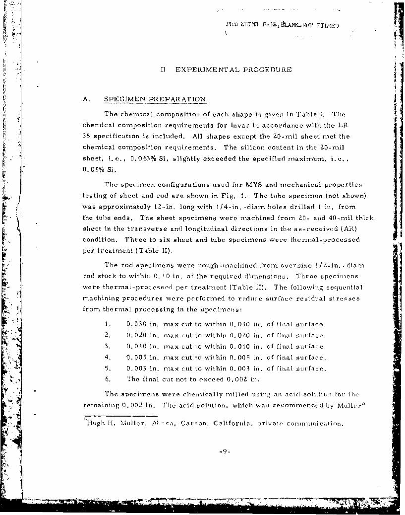
A. SPECIMEN PREPARATION
The chemical composition of each shape is given in Table 1. The
chemical composition requirements for Invar in accordance with the LR
35 specification is included. All shapes except the 20-mil sheet met the
chemical composifion requirements. The silicon content in the 20-mil
sheet, i. e., 0. 063% Si, slightly exceeded the specified maximum, i.e.,0. 05% Si.
The specimen configurations used for MYS and mechanical properties
testing of sheet and rod are shown in Fig. 1. The tube specimen (not shown)
was approximately 12-in, long with 1/4-in. -diam holes drilled I in. from•.''• the tube ends. The sheet specimens were machined from 20- and 40-rail thick
- •sthe the transverse and longitudinal directions in the as-received (Am)
condition. Three to six sheet and tube specimens were thermal-processed
i• per treatment (Table II),
The rod specimens were rough-machined from oversize I/ 2-in. -diamn
rod stock to within 0. 10 in. of the required dimensions. Three specimens
were thermal-proceoqed per treatment (Table i1). The following sequential
machining procedures were performed to reduce surface residual stresses
from thermal processing in the specimens:
1. 0.030 in. max cut to within 0. 030 in. of final surface.
2. 0.020 in. max cut to within 0. 020 in. of final surface.
3. 0.010 in. max cut to within 0.010 in. of final surface.
4. 0.005 in. max cut to within 0. 00; in. of final surface.
ft. 0.003 in. max cut to within 0.003 in. of final surface.
6. The final cut not to exceed 0.00Z in.
The specimens were chemically milled using an acid solution for the
remaining 0.002 in. The acid solution, which was recommended by Muller*
Hugh H. Muller, Al co, Carson, California, private corunnlnicationi.
WILI ,-

x
C>m
U)
4))'0 U n .0 SdC
NI I It D
10 N . 0 - - ) r
Cd
01
v v
41)
0) U0
CPu u0 P, (1), IZ
4) 4w4)~~ ICm 61

r�.
p __
0.500 I
1.00
1�2� fl.320 -.------10.500 RADIUS 0.314 DIAMETER
j Ia) SHEET SPECIMEN TWO HOLES
-4- --4.00 NOMINAL---
Ii I 20.250 RADIUS Ity�caI)
0.4000.000-20 THREAl Itypicall
WI ROD SPECIMEN
Fig. 1. Specimen configurations used for Irwar ptogram
Vi
K-11-

0 0
A xAL
0o 0 c
10 u
c 0 0
N~ ~~ 0O ~ 0'0 0 00
[T4
00 00 a, ~ 0i 0~ 0
ItN
.-. U
~~mI ~E.: I~~3 If
UOU
rd- '.
N q
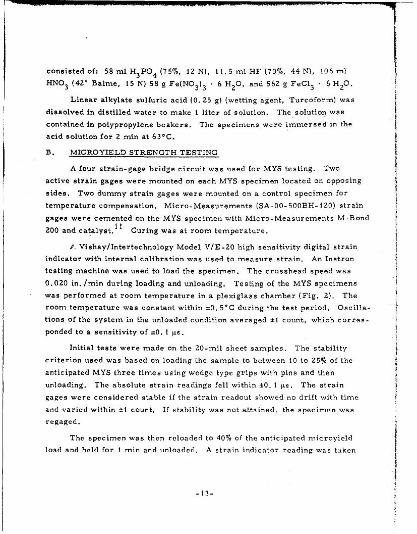
consisted of: 58 ml HPO4 (75%, 12 N), It.5 ml HF (70%, 44 N), 106 mlHNO 3 (42° Balme, i5 N) 58 g Fe(NO3 )3 . 6 H 2 0, and 562 g FeCl 3 6 H 2 .0.
Linear alkylate sulfuric acid (0. 25 g) (wetting agent, Turcoform) was
dissolved in distilled water to make I liter of solution. The solution wascontained in polypropylene beakers. The specimens were immersed in the iacid solution for 2 min at 63 0 C.
B. MICROYIELD STRENGTH TESTING
A four strain-gage bridge circuit was used for MYS testing. Two
active strain gages were mounted on each MYS specimen located on opposing
sides. Two dummy strain gages were mounted on a control specimen for
temperature compensation. Micro-Measurements (SA-00-500BH-120) strain
gages were cemented on the MYS specimen with Micro-Measurements M-BondIi
200 and catalyst. Curing was at room temperature.
f. Vishay/Intertechnology Model V/E-20 high sensitivity digital strain
indicator with internal calibration was used to measure strain. An Instron
testing machine was used to load the specimen. The crosshead speed was
0.020 in. /min during loading and unloading. Testing of the MYS specimens
was performed at room temperature in a plexiglass chamber (Fig. 2). The
room temperature was constant within ±0. 5°C during the test period. Oscilla-
tions of the system in the unloaded condition averaged ±1 count, which corres-
ponded to a sensitivity of ±0. 1 4e.
Initial tests were made on the 20-mil sheet samples. The stability
criterion used was based on loading ýhe sample to between 10 to 25% of the
anticipated MYS three times using wedge type grips with pins and then
unloading. The absolute strain readings fell within ±0. I ýLe. The strain
gages were considered stable if the strain readout showed no drift with time
and varied within ±1 count. If stability was not attained, the specimen was
regaged.
The specimen was then reloaded to 40% of the anticipated microyield
load and held for I min and unloaded. A strain indicator reading was taken I
--13-
I

I IA
Fg2, l~xpe rilnental tes~t sotup foi XIN Y S (1letu rivninat i ofl
I.: L II -

after 3 to 5 min, which was the average time required for the specimen to
become stable. Between 4 and 15 successively 'higher load cycles were
I ~employed to reach one unit of plastic rnicrostrain. The test continued until
at least 30 ýLe units of plastic strain were attained.
The effect of time at stress was im-re sti gated by successively loading
a 20-nil. sheet sample to 22. t ksi (the mo~asured MYS in this 'nase). The
. micrec.creep is 0. 44 týte/,nin (FMg. 3), It was concluded that the I1-min
time at.stress had no significant effect on MYS determination.
2.8 -
:z* / ~ 2.4-
~2.2 -
c-S2.0
/ 1.8~1.6
1.2 -SLOPE =0.044 u.e/mln
1.00
CUMULATIVE TIME AT STRESS (min)
Fig. 3. Plot of cumulative plastic microstrain versus cumulativetin-e at stress. (The applied stress wag 22. 1 ksi,i.e., the MYS.
-15-

I I I I l l I I I I II I ! -
III. RESULTS AND DISCUSSION
A. METALLOGRAPHY
A typic~i microstructure of 20-mil sheet is shown in Fig. 4. The
etchant was a i:1 solution of concentrated HCI and HNO 3 with 10 drops of 10%FeCl 2 added per 25 mil of solution.." There were no appreciable inclusions
present among the equiaxed grains with annealing twins (ASTM grain size 8.5).A typical riicrostructure of 40-rail sheet that consisted of equiaxed grains
with anne-cling twins is shown in Fig. 5. The microstructure did not changewith processing. Platelike inclusions were observed with the plate plane
parallel/to the sheet. These were identified as (Fe, Ni)S. They are assumed
to have/ r- effect on longitudinal and transverse properties. The microstruc-
ture o' rod and tube are shown in Figs. 6 and 7, respectively. The equiaxedgrains with annealing twins did9 not change -ith processing.
/ Figure 8 is a scanning electron micrograph of the 40-mil sheet. Thetwo/illuminated square areas (A and B) were subjected to energy despersive
an'ilysis of x-rays (EDAX). The results are shown in Figure 9. The y-axisis the intensity and is the total number of x-ray counts accumulated in a
given time period. The x-axis is the energy of the x-rays in KeV. The first
two peaks correspond to the K and K of Fe, respectively, and the remainingtwo peaks correspond to the K and K of Ni, respectively. The bars in Fig. 9
correspond to iron and nickel peaks in the grain boundary area, whereas thewliite dots correspond to a similar scan of the grain interior, as indicated
in Fig. 8. There was no relative difference in iron and nickel intensity be-tween the two two iregions. EDAX of the rod showed similar results. Theseresults indicate that the Ni and Fe are uniformly distributed in the Invar.
B. MECHANICAL PROPERTIES
Mechanical properties included hardness, yield strength (YS), andultimate tensile strength (UTS), Young's modulus, and percent elongation.
T. J. Bertone, The Aerospace Corporation, private communication, June 1976.
-17-

Fig. 4. Optical micrograph of as-receivedInvar 20-mil she et in longitudinaldirection
I01
72%
Fig. 5. Optical micrograph of Invar 40-mil sheet(40-Z heat treatment) in longitudinaldirection

31b.
A iA
"24"4
tret et in rada ieto

Ii,
4A4/
50 p7
Fig. 6. Optical micrograph of Envar rod (R- i heattreatment) in radial direction
Fig. 7. Optical micrograph of Invar tube (T-l heat
treatment) in radial direction
-19-

Fig. 8. SEM micrograph of Invar 40-mil sheet(40- 1 heat treatment) in longitudinaldirection showing square areas A andB used for EDAX
Fig. 9. EDAX of Invar 40-mil sheetin square areas A and Bshown in Fig. 8. The twohighest intensities corre-spond to Fe and Ni,respectively
-20-

Results are summarized in Table III. Standard deviations given are based on
3 to 6 samples. The YS of the sheet is higher than the YS of the rod. The
higher YS is attributed to longitudinal stretching. Increase in longitudinal
stretching increased the YS. The YS in the longitidinal direction is higher
than in the transverse direction. The thermal treatments, i.e., -1 and -2,
given to the AR sheet did not significantly affect the YS. The YS of the rod
""was not significantly affected by the various thermal treatments. The UTSand elongation of the sheet are not significantly affected by thermal-
mechanical processing.
C. MICROYIELD STRENGTH
The microyield strength results are summarized in Table III. The
mean represents 3 - 6 tests. When no standard deviation is given, only one
MYS test was performed.
tdfThermal treatments R-i, R-2, and R-3 represent practical approaches
to different combinations of dimensional stability and thermal expansion
coefficients. The R.- I heat treatment for the rod Is based on the studies of12 1BF .Lement and Eberly to achieve a conmbination of low thermal expansion
with good dimensional stability. The 315*C thermal treatment is effective in
relieving the high residual compressive stresses formed at the surface byquenching from 830C.. but raises the thermal expansion coefficient. The
96'C thermal treatment essentially completes the y-expansion with a net
expansion of approximately 50 •i.. The R-2 thermal treatment includes a205'°C thermal treatment that also relieves residual stresses but does not
raise the thermal expansion coefficient as high as the R- 1, The thermal
treatment at 700C only partially completes the -y-expansion, which causes
dimensional instability. The R-3 thermal treatment produces a dimensionally:,• stable structure, but has a high thermal expansion coefficient. The MYS was
"4A( the same for R- I and R-Z thermal treatment; R-3 thermal treatment gave the
highest MYS. The increase in MYS of the rod is attributed to the slo'.\ furnace
cool from 830'C. The increase in the MYS of the tube is also attributed to
the s!ow furnace cool from 370 C. However, the nearly twofold increase in
I.
-21 -
". MU'. IV,

0 0.
Cd-o
041 44 -H -+ 44 41
CD~ 0 C-A- 'j N 0C.
0H H
0 r- NM' 0 ' '0 L
C) 0h) Cý C 0 0 0 C444 44 -H4r44 - 4 -4
- 0ý 44 O~a' IA 0
04
I-.
a, - , 0- U)0)Li 04 0
'0 mA N LA m MO N
Cd- 4 441- -4 + 4- -+1
bfJ 00 Ln C6 - .0 0 0 i
41*/ *0'. -D COCo 0 0' Co j I-A pQ
0 r++ 41 + +Li-.4 - 00 c4 0 0 0 0 0
-H- 4J4 41--4 4 -4444uA 06 0 1 IC 6 0 ; C
di - c~L O C 1- 0 '1 a O'* Li ~ p . . .
.1Z)4 E-4
tn of
-22-

"' I
the MYS of the tube, which also had a slow cooling step in comparison to the
"rod, was not resolved. The effect of the R-3 thermal treatment on MYS is10consistent with the results of Hem-miings and Perkins, who reported that slow
cooling in the temperature range 200 to 400' C produces a higher MYS.
ThThe MYS is also increased by stretching. The MYS of 20-mil sheet is
increased with 1/2% stretching if 10 kei is assumed the nominal MYS of,•- '*- 7
• annealed Invar. There is no significant difference between the MYS in
the longitudinal and transverse directions. However, the MYS in the longitu-
dinal direction of the 40-mil sheet with 276 stretching is higher than Z0-mil
sheet, whereas the MYS of 40-mil sheet in the transverse direction is the
same as the 20-mil sheet. Although stretching increases the MYS, Imgramr
Set al.4 reported that plastic prestaining of 2.5 and 51 lowered the MYS of
Ni-Span..C. However, the chemical composition and mechanical properties
of this material are significantly different from Invar, i. e., chemical compo-
si~ion of Ni-Span-C is typically 0. 6% Al, 5. 4% Cr, 42. 2% Ni, 2. 4% Ti, and
Sbalmnce Fe. On the other hand, Marschall '! has shown that 35% reduction by
cold-working increases the MYS of Invar.
D. STRESS VERSUS PLASTIC STRAIN CURVES
Two types of stress-plastic strain behavior are characterized. The
20-mil sheet exhibited a smooth curve as shown in Fig. 10. The 40-mil sheet
in the longitudinal direction exhib:ted an S-shaped curve (Fig. 11), whereas
in the transverse direction, the curve was similar to the 20-mil sheet (Fig. 10).
The curves for the rod were intermediate.
The curves f-r the tube material were similar to the 40-rail sheet in
the longitudinal direction. Work by several investigators suggests
that most materials follow a logarithmic stress-plastic strain relationship
of the type
a Ke np
C. W. Marschall, Battelle Columbus Laboratories, private communi-cation, 2 July 1975.
""-Z3-

'35
I30
~2514
re~j MICROYIELD STRENGTH
V 15
-!:a.
0 2 4 6 8 O 12 14 6 18
PERMANENT DEFORMATION (I x I0 in.in.)
Fig. 10. Stress-plastic strain curve of a 20-mil sheet
-- 24-
.ii4 0 1 14 16 .

Z2
I30 * 40-2-L'~40-2-T LONGITUDINAL
28
26
24
22I 20 -T A S E S~18
~16
~14
10
2 5
0 0.2 0 ~.4 . 6.L~ 0. 1.01.

where K is the preexponential coefficient, n is the microstrain hardeninge.xponent, and E is the plastic strain. A smooth curve (Fig, 10) can be
described by one set of K and n, whereas an S-shaped curve requires two,. sets of these parameters (Fig, 12). A statistical analysis of all data was
performed. Logarithmic curves were fitted to data below and above the MYS
.separate) - and to the combined data. The values of the coefficient of
correlation (R) and the number of experimental data points (N) are given in
Table IV, Only in the case of the 40-mil sheet in the longitudinal direction
-did R for data below, the MYS exceed R for the combined data. This signified
that the data for the 40-rnil sheet in the longitudinal direction is more accu-
Srarely 6escriled 'by two sets of K and n rather than one set of K and n.
,The data described by two sots of K and n suggest that other deformation
processes art: beginning to occur due to the 2% stretching. In comparing the
combined data curves, neither n nor K showed any significant trend with
thermal mechanical processing for any particular shape, The 20-mil sheet
has the highest K values and lowest n values, whereas the rod has the lowest
K values and highest n valucs.
.1
S~I
-- 26
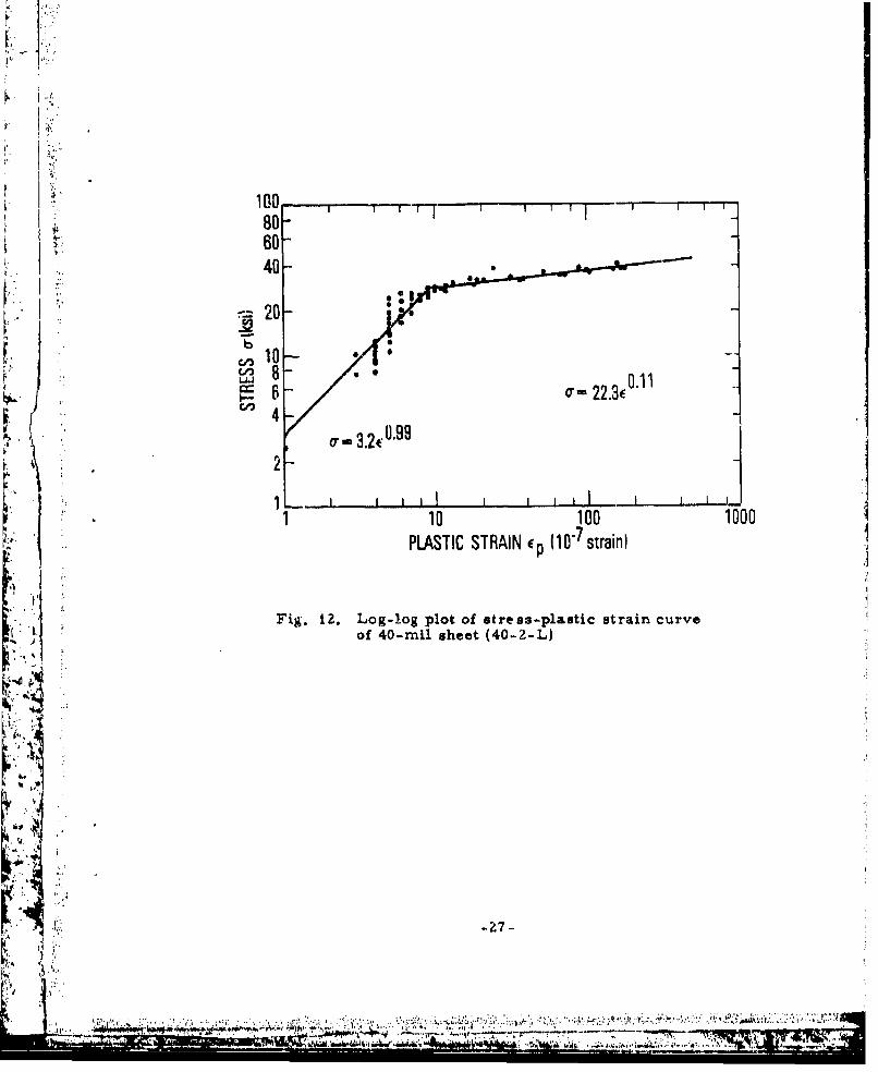
100 _I 80-60-40--
F 2-~
C/3 a- 22.31C4-
11 10 100 1000PLASTIC STRAIN ep (1~straini
Fig. iZ. Log-log plot of stress-plastic strain curveof 40-mil sheet (40-2-L)
4k7
II ~~ WI~ ;7"1'

Lo Z% '0 LAIn COi (30 cl -000 e N
0N t.0 'On 0n vr- ~ A~. I'- 0'.
mO' 0' In 1O - 0 'CO C
m00' cN N 4 OIn co 0 'D In
00 00 000 C 000 0
0D a- .0'N In r- 0 In In 0 4
~ c ~ - -N a'C. CO .qý a'('C
I~cy 0- tN N N N N
a, 000000 0-a a ,0 00 00 0 0,
4j ) w N '-4 N - N N - ~ - -
14 V1 .; C; C; C; . .
CIS U4 -, 1.: -; U; C z 1 0 4
N . -4 N U) N In N m ~ -
NN 00 -N) N) .IA 'i v a C t w t Q '.0
o 00000 0O t -00 Ul 000% - '
- ~ ~ ~ ~ ~ ~ ~ C '.0 - OC C' O'0 N ';~O- L
r4 co 0
a,4
It -- Ln'
4j I.j E- 0 .V -1)
E-i 0.E 4',
a4*

r, IL.'
IV. CONCLUSIONS
The microyield strength increases with slow furnaco cooling from
temperatures> 390 0 C.
', i~ The microyield strength of sheet in the longitudinal and transverse
directions increases with up to 2% longitudinal stretching. Two percent. •stretching produces a higher rnicroyield strength in the iongitudinal direc-
"tion than in the transverse direction,
I J ~ Most stress-plastic strain curves can be described with the empirical
relationship a = Ke . In the case of 40 mil sheet with 2% stretching theI, p
stress-plastic strain curves are divided ir,•o two segments and are described
with two sets of K and n,
4 J.
"-29
t I
•tI
:i'
:L.1
:. ~- 29 -- :
3 ;,I. ;

T.-
REFERENCES
1. J. S. Marsh, Alloys of Iron and Nickel, Vol. I, Special Purpose Alloys,
9. MeGraw-Hill '3ook Co., Inc., New York, (1938) pp. 135-1|3.
2. W. S. McCain, and R. E. Maringer, Mechanical and Physical Propertiesof Invar and Invar-Type Alloys, DMIC Memorandumn No. Z07
S[3i August 1965).
3. P. F. Weihrauch and M. J. Hordon, The Dimensional Stability on.,. Selected Alloy Systemns, AD613931 Alloyd'General Corp., Navy
"Contract N 140(131)-75-98B (August 1964).
4. A. G. Imgram, R. E. Maringer, Lnd F. C. Holden, Study of Micro-
plastic Propertie's and Dimensional Stabilit of Materials,I AFML-TR-67-232, Wright-Patterson Air Force Base, Columbus, Ohio•." (August 1968).
5. L. M. Shetky, The Properties of Metals and Alloys of ParticularInterest In Precision Instrumnent Construction, R-i 37, MIT Instrumenta-tion Laboratory, Cambridge, Massachusetts (January 1957).
6. UNISPAN LR 35 Composition Specifications, Universal Cyclops Specialty
Steel Division, Pittsburgh, Pennsylvania
7. G. W. Geil and I. J. Feinberg, Microplasticity I - Measurement of
Small Microstraints at A.bi ent Terneratures, Report No. 9996 (1969)
and Microplasticity II - MTc'ostrain Bhavior of Normalized 4340 Steel
and Annealed Invar, Report No. 9997"atonal Bureau of Standards,.Washington, D. C.
8. G. W. Geil, I. J. Feinberg, and R, B. Clough, "Temperature Changes
"in Specimens in Microplasticity Tests, Met. Trans. 1, 1845-1851.. (1970).
9. P. L. Hemmings and R. A. Perkins, "The Effect of Thexmal Treat-
naents in the Micromechanical Behavior of Invar, " presented at ASM,Materials Science Seminar, Cincinnati, Ohio, November 1973.
i<:1: 0. C. W. Marschall, "Lowering the Thermal Expansivity of Invar by€..Dc rburation," Proceedi~ngs of the 2-Ist National SAMPE Sy~m osi__,
Los Angeles, 6-8 April 1976, SAMPE, Azusa, California (1972).
fI
z3.04 -30

r, 4
"" 11. Strain Gage Installations With Certified M-Bond 200 Adhesives,Inst:Puction Bulletin -127-2 (July 1971), Micro-MeasurementsDivision of Vishay Intertechnology, Inc., Road, Romulus, Michigan.
,'. 3 B.S. ST.ment, B. L. Averbach, and M. Cohen, "The DimensionalBehavior of Invar, " Trans. ASM, 43, 1072-1097 (1951).
13. W. S. Eberly, "How to Make Invar Stay Put," Prod. Eng. 28, 80-81,I. (1957).
14. C. W. Marshall and R. E. Maringer, "Stress Relaxation as a Sourcero .
of Dimensional Instability, " J. Mater. 6, 374-387, June (1971).
5lb. R. E. Maringer, M. M. Cho, and F. C. Holden, Stability of Structural"Materials for Spacecraft Aplications, " Con'tract No. NA 5- 10267,NASA-Cr.R.97844, NASA, Washington, DC. (16 April 1968).
It
-31 -
- Aid, .Uý

I ILABORtATORY OPERATkI~NS
The Laboratory Operations of The Aerospace Corporation Is conducting
experlmental and theoretical invostijatior.s necessary for the evaluation and
application of scientific advances to new military concepts and systems. Var-
satility and flexibility have been developed to a high degree by the laboratorypersonnel in dealing with the many problems encountered in the nation's rapidlydeveloping space and missile systems, Expertise in the latest scientific devel.
oupments is vital to the accomplishment of tasks related to these problems. The
laboratories that contribute to this research aret
b Ibrar Launch and reentry aerodynamics, heat trans-fer, reny physics. cherical kinetics, structuralmechanics, flight dynamics,atmospheric pollution, and high-power gas lsers,
Chemistry and Physics Laborator l Atmospbetlc reactions and astmos-phericoprn', chemical reactions on polluted atmospheres, chemical reactionsof excited species in rocket plumes, chemical thermodynamics, plasma andlaser-!nduced reactions, laser chumistry, propulsion chcmlstry, space vacuumand radiation effects on materials, lubrication and surface phenomena, photo.senritive nyaterials and sensors, high precision laser ranging, and tihe appli.cation of physics and chemistry to problems of law enforcement and biumedicino,
XElectron|i' Research Laborator. Electromagnetic theory, d, nice6, and
propagation phenomneno, including plasma electrornagnetics; quantum electronics,lasers, and electro-optics; communication sciences, applied electronics, semi-conducting, superconducting, and crystal device physics, optic:al and acousticalimaging; atmospheric pollution: millimeter wave and far -infrared technology.
Materials Scienes Laboratory: Development of new materials; metalmatrix composites an ndw arms o carbon; test and evaluation of graphiteand ceramics in reentry; spLcecraft materials and electronic components innuclear weapon. environment: application of fracture mechanics to stress cor-
reoion and fatigue-induced fractures in structural metals.
Space Sciences Laboratoayt Atmnospheric and ionospheric physics, radia-tion firnm Ft at- t•err, density and composition of the atmosphere, auroraeand airgloww niagnetospheric physics, cosmic rays, generation and propagationof plasma wivus in thle magnatospheir; solar physics, studies of solar magneticfieldst space astrdnomy, x-ray astronomy; the effects of nsclear explosions,makinctic storms, and solar activity ont the earth's atmosphere, ionnoaph~re, and
riagnetosphcre; the effects of optical, electromag netic, and particulate radfi-tions in space an space sy~teniu."t ip n e eTHE AEROSPACE CORPORATION
El Segundo, California
~AI
•5'
S:A

LABORATORY OPERATIONS
The Laboratory Operations of The Aerospace Corporation is conducting
experimental and theoretical investigations necessary for the evaluation and
application of scientific advances to new military concepts and systems. Ver-
satility and flexibility have been developed to a high degree by the laboratory
personnel in dealing with the many problems encountered in the nation's rapidly
developing space and missile systems. Expertise in the latest scientific devel-
opments is vital to the accomplishment of tasks related to these problems. The
laboratories that contribute to this research are:
Aerophysics Laboratory: Launch and reentry aerodynamics, heat trans-fer; reentry physics, chemical kinetics, structural mechanics, flight dynamics,atmospheric pollution, and high-power gas lasers.
Chemistry and Physics Laboratory: Atmospheric reactions and atmos-pheric optics, chemical reactions in polluted atmospheres, chemical reactionsof excited species in rocket plumes, chemical thermodynamics, plasma andlaser-induced reactions, laser chemistry, propulsion chemistry, space vacuumand radiation effects on materials, lubrication and surface phenomena, photo-sensitive materials and sensors, high precision laser ranging, and the appli-cation of physics and chemistry to problems of law enforcement and biomedicine.
Electronics Research Laboratory: Electromagnetic theory, devices, andpropagation phenomena, including plasma electromagnetics; quantum electronics,lasers, and electro-optics; communication sciences, applied electronics, semi-conducting, superconducting, and crystal device physics, optical and acousticalimaging; atmospheric pollution; millimeter wave and far-infrared technology.
Materials Sciences Laboratory: Development of new materials; metalmatrix composites and new forms of carbon; test and evaluation of graphiteand ceramics in reentry; spacecraft materials and electronic components innuclear weapons environment; application of fracture mechanics to stress cor-rosion and fatigue-induced fractures in structural metals.
.Space Sciences Laboratory: Atmosopheric and ionospheric physics, radia-tion from the atmosphere, density and composition of the atmosphere, auroraeand airglow; maagnetospheric physics, cosmic rays, generation and propagationof plasma waves in the magnetosphere; solar physics, studies of solar magneticfields; space astronomy, x-ray astronomy; the effects of nuclear explosions,ra), nvtic storms, and solar activity on the earth's atmosphere, ionosphere, andmagnetosphere; the effects of optical, electromagnetic, and particulate radia-tions in space on space systems.
THE AEROSPACE CORPORATIONEl Segundo. California