Embed Size (px)
Citation preview

1
4th International Conference on Earthquake Geotechnical Engineering
June 25-28, 2007 Paper No. 1702
EFFECTS OF SEISMIC EARTH PRESSURE AND SIDEWALL
FRICTION ON PILE STRESS DURING SOIL LIQUEFACTION
Shuji TAMURA1, Tsuyoshi IMAYOSHI2 and Tadashi SAKAMOTO2
ABSTRACT Earth pressure and sidewall friction were investigated based on dynamic centrifuge tests on a superstructure-footing model that is supported on piles in either dry sand or saturated liquefiable sand. The following conclusions were reached: (1) the liquefied layer under the non-liquefied crust affects not only the superstructure-footing response but also the earth pressure and sidewall friction. The amplitudes of the total earth pressure and sidewall friction in liquefaction test are much greater than those in non-liquefaction test. Furthermore, the total earth pressure and sidewall friction in liquefaction test tends to be in phase with the superstructure-footing inertia. Therefore, the shear force amplitude at the pile heads becomes large; (2) in non-liquefaction testing, the total earth pressure and sidewall friction that are generated as reaction forces of the superstructure-footing inertia counter the inertial force transmitted from the superstructure-footing to the pile head. Consequently, the shear force amplitude at the pile heads is smaller than the superstructure-footing inertia amplitude.
Keywords: Earth pressure, Friction, Embedded footing, Pile, Sand, Liquefaction
INTRODUCTION Lateral response of an embedded footing affects pile stress during an earthquake (e.g. Sugimura and Hirade, 1984). Several studies have assessed earth pressure and friction acting on an embedded footing. The relative contributions of the base, sidewall and active/passive side of an embedded footing in dry sand with Dr=75% were evaluated based on cyclic lateral loading centrifuge tests (Gadre and Dobry, 1998). That study showed that the contribution of the passive side accounts for more than half of the total lateral capacity of the embedded footing. Effects of an embedded footing on pile stress were investigated using shaking table tests with a silicone soil model (Imaoka et al., 1998). Results indicated that the lateral response of an embedded footing reduces pile stress remarkably in the frequency range near the natural frequency of the superstructure. In addition, shaking table tests using a polyacrylamide and bentonite soil model (Iiba et al., 2003) showed that the lateral response of an embedded footing is very effective for reducing pile stress. On the other hand, Tamura et al. (2002) reported that the lateral response of an embedded footing, which comprises earth pressure and fiction, tends to increase pile stress in liquefied sand based on large-scale shaking table tests. However, knowledge of earth pressure and friction during soil liquefaction and effects of earth pressure and friction on pile stress remains limited. This study is intended to: 1) examine the effects of liquefied soil layer on development of earth pressure and sidewall friction acting on an embedded footing in non-liquefied crust; and 2) investigate the effects of total earth pressure and sidewall friction on the shear force at pile heads. For those
1 Associate Professor, Disaster Prevention Research Institute, Kyoto University, Japan, Email: [email protected] 2 Graduate Student, Kyoto University, Japan

2
purposes, dynamic centrifuge tests on a superstructure-footing model that is supported on piles in either dry sand or in saturated liquefiable sand were performed. In addition, a simple method is presented to evaluate not only the earth pressure on active and passive sides, but also the sidewall friction of an embedded footing.
CENTRIFUGE TESTS PERFORMED Test model Centrifuge tests were performed at 40 g centrifugal acceleration using the geotechnical centrifuge at the Disaster Prevention Research Institute, Kyoto University. A pile-footing-superstructure model was prepared in a laminar shear box with inner dimensions of 450 mm (length) × 150 mm (width) × 200 mm (height). Two cases of the performed tests are presented in Fig. 1. The soil profile in Case 1 con-sists of a 4.0 cm layer of dry coarse sand crust, which is Toyo silica sand #2 (D50=1.92 mm) overlying a 16.0 cm layer of dry fine sand deposit, which is Albany silica sand #48 (D50=0.29 mm). The soil profile in Case 2 resembles that of Case 1, except that the fine sand deposit is saturated and the water level was located at GL -3.0 cm. A viscous fluid made of Metolose (Shin-Etsu Chemical Co.), which has a viscosity of 40 times that of water, was used. A sketch and conditions of a piles-footing-superstructure model is shown respectively in Fig. 2 and Table 1. A 2 × 2 pile model was used for the tests. The 6-mm-diameter piles had flexural rigidity EI of 1.20 × 10⁻² kNm2. The lid-shaped footing was modeled with rigid brass of dimensions 80 mm (shaking direction) × 50 mm (width) × 43 mm (height). The pile heads were linked rigidly to the upper plate of the footing; their tips were also rigidly linked to the laminar shear box. The strain gauges at the pile heads were not in contact with the soil. Therefore, the shear force at the pile head, as calculated by the
Accelerometer Pore Pressure Transducer
Silica sand No.2 Silica sand No.2
150
Saturated sandDr=45%
Silica sand No.2 40160
450(㎜)
Dry sandDr=45%
Silica sand No.2
Pile
Strain gage
Load cell
Plate
Superstructure
Footing
Accelometer
Figure 1. Setup for centrifuge tests on piles-footing-superstructure model
Figure 2. Piles-footing-superstructure model
Unit Prototype Model
Pile Diameter m 0.24 0.006E・I MNm2 30.72 1.20×10⁻⁵
Footing Mass kg 45,760 0.715Length (L×B×H) m 3.20×2.00×1.72 0.080×0.050×0.043
Structure Mass kg 66,240 1.035Natural frequency Hz 2.5 100
Table 1. Conditions of piles-footing-superstructure system in prototype and model scale
(a) Case 1 (b) Case 2
Accelerometer

strain differentiation, was inferred to have been measured accurately, and independently of the soil effects. Plates supported by three load cells were set up on the right and left sides of the footing to evaluate earth pressure acting on the footing. The surface of the footing model is smoother than that of a prototype. Therefore, a fine grade of sandpaper #800 was pasted on the right and left sides and side-walls of the footing. The superstructure was modeled with rigid brass. The mass of the superstructure was 1.035 kg; that of the footing was 0.715 kg. The natural frequency of the superstructure under the fixed footing conditions was about 100 Hz. All tests were excited using Rinkai92, which is a synthe-sized ground motion for the Tokyo Bay area. All data presented in the following sections are of pro-totype scale. Evaluation of sidewall friction Tamura et al. (2005) presented a simple method to evaluate the sidewall friction of an embedded footing, of which the following outline is given. Figure 3 depicts a schematic figure showing forces acting on pile heads, an embedded footing, and a superstructure. The sum of the shear force at pile heads, Q, can be expressed as
Q=Pet + Pfs + Pfb + Fis + Fif , (1) in which Pet=total earth pressure, Pfs=sidewall friction, Pfb=base friction, Fis=superstructure inertia, and Fif=footing inertia. The total earth pressure, Pet has the value of
Pet = PR – PL , (2) where PR=earth pressure acting on the footing’s right side and PL=earth pressure acting on the foot-ing’s left side. The earth pressure, PR and PL can be measured using the plate supported by the load cells. Considering that the base friction, Pfb is neglected, the sidewall friction, Pfs is given as
Pfs = Q – Pet – Fis – Fif . (3) The shear force at the pile heads, Q, can be evaluated by differentiation of the strain at the pile heads. The inertial forces, Fis and Fif, are equal to the product of the mass and measured acceleration.
TEST RESULTS Soil, Footing and Superstructure Response Figures 4 and 5 respectively depict the time histories of the acceleration of input, the ground surface and footing, and superstructure in Cases 1 and 2. The excess pore water pressure ratio at G.L. –2.8 m in Case 2 is shown in Fig. 6. The excess pore water began to increase at about 10 s and reached the
Superstructure inertia, Fis
Footing inertia, Fif
Earth pressure (Left side), PL
Earth pressure (Right side), PR
Shear force at pile head, Q
Sidewall friction, Pfs
Base friction, Ffb
Figure 3. Forces acting on superstructure, embedded footing and pile head

4
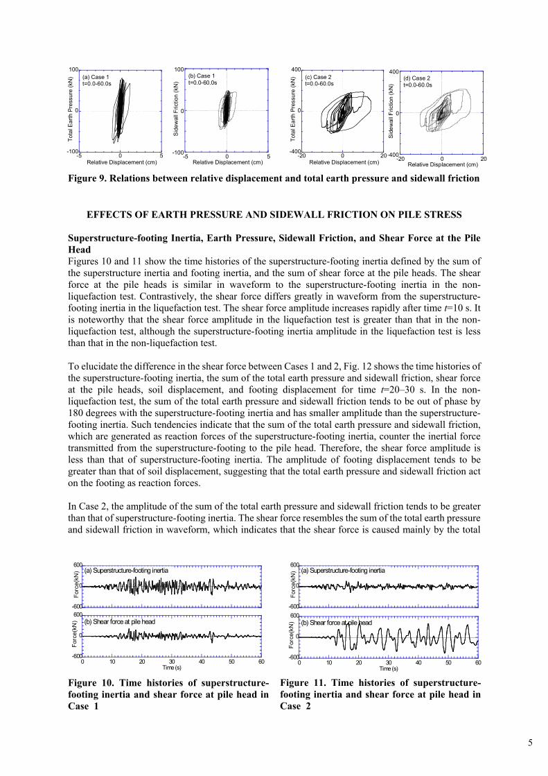
effective confining pressure at about 20 s. The acceleration amplitudes of the ground surface, footing and superstructure in the liquefaction test tend to be smaller than those in the non-liquefaction test, although the input accelerations in both cases are almost identical. Earth Pressure and Sidewall Friction Figures 7 and 8 respectively portray the time histories of the total earth pressure and sidewall friction acting on the footing in Cases 1 and 2. The total earth pressure and sidewall friction in Case 2 are similar in waveform to those in Case 1 before soil liquefaction. After liquefaction, the amplitude of the total earth pressure and sidewall friction in Case 2 became larger than those in Case 1. Especially, the maximum amplitude of sidewall friction in Case 2 is about four times greater than that in Case 1. These indicate that the liquefied layer affects the total earth pressure and sidewall friction acting on an embedded footing in the non-liquefied crust. The relations between the relative displacement and the total earth pressure and sidewall friction are shown in Fig. 9. The relative displacement between the footing and soil in the liquefaction test is about 10 times greater than that in the non-liquefaction test, indicating the liquefied layer under non-liquefied crust generates large relative displacement. The total earth pressure and sidewall friction exhibit highly nonlinear behavior in the liquefaction test.
-400
0
400
Acc.
(cm
/s2 ) (b) Ground Surface
-400
0
400
Acc.
(cm
/s2 ) (b) Ground Surface
-400
0
400
(#ABL)(#AFT)
Acc.
(cm
/s2 )
SuperstructureFooting
(a) Superstructure & footing
-400
0
400
(#ABL)(#AFT)Ac
c.(c
m/s
2 ) (a) Superstructure & footing
SuperstructureFooting
-400
0
400
0 10 20 30 40 50 60
Acc.
(cm
/s2 ) (c) Input Acceleration
Time (s)
-400
0
400
0 10 20 30 40 50 60
Acc.
(cm
/s2 ) (c) Input Acceleration
Time (s)
00.20.40.60.8
11.2
0 10 20 30 40 50 60u/σ
v'
Time (s)
-300
0
300
Forc
e(kN
) (a) Total earth pressure
-300
0
300
Forc
e(kN
) (a) Total earth pressure
-300
0
300
0 10 20 30 40 50 60
Forc
e(kN
) (b) Sidewall friction
Time (s)
-300
0
300
0 10 20 30 40 50 60
Forc
e(kN
) (b) Sidewall friction
Time (s)
Figure 4. Time histories of acceleration in Case 1
Figure 5. Time histories of acceleration in Case 2
Figure 6. Time history of excess pore water pressure ratio in Case 2
Figure 7. Time histories of total earth pres-sure and sidewall friction in Case 1
Figure 8. Time histories of total earth pres-sure and sidewall friction in Case 2
5
EFFECTS OF EARTH PRESSURE AND SIDEWALL FRICTION ON PILE STRESS
Superstructure-footing Inertia, Earth Pressure, Sidewall Friction, and Shear Force at the Pile Head Figures 10 and 11 show the time histories of the superstructure-footing inertia defined by the sum of the superstructure inertia and footing inertia, and the sum of shear force at the pile heads. The shear force at the pile heads is similar in waveform to the superstructure-footing inertia in the non-liquefaction test. Contrastively, the shear force differs greatly in waveform from the superstructure-footing inertia in the liquefaction test. The shear force amplitude increases rapidly after time t=10 s. It is noteworthy that the shear force amplitude in the liquefaction test is greater than that in the non-liquefaction test, although the superstructure-footing inertia amplitude in the liquefaction test is less than that in the non-liquefaction test. To elucidate the difference in the shear force between Cases 1 and 2, Fig. 12 shows the time histories of the superstructure-footing inertia, the sum of the total earth pressure and sidewall friction, shear force at the pile heads, soil displacement, and footing displacement for time t=20–30 s. In the non-liquefaction test, the sum of the total earth pressure and sidewall friction tends to be out of phase by 180 degrees with the superstructure-footing inertia and has smaller amplitude than the superstructure-footing inertia. Such tendencies indicate that the sum of the total earth pressure and sidewall friction, which are generated as reaction forces of the superstructure-footing inertia, counter the inertial force transmitted from the superstructure-footing to the pile head. Therefore, the shear force amplitude is less than that of superstructure-footing inertia. The amplitude of footing displacement tends to be greater than that of soil displacement, suggesting that the total earth pressure and sidewall friction act on the footing as reaction forces. In Case 2, the amplitude of the sum of the total earth pressure and sidewall friction tends to be greater than that of superstructure-footing inertia. The shear force resembles the sum of the total earth pressure and sidewall friction in waveform, which indicates that the shear force is caused mainly by the total
-600
0
600
0 10 20 30 40 50 60
Forc
e(kN
) (b) Shear force at pile head
Time (s)
-600
0
600
0 10 20 30 40 50 60
Forc
e(kN
) (b) Shear force at pile head
Time (s)
-600
0
600
Forc
e(kN
) (a) Superstructure-footing inertia
-600
0
600
Forc
e(kN
) (a) Superstructure-footing inertia
-5 0 5-100
0
100
Relative Displacement (cm)
Sid
ewal
l Fric
tion
(kN
)
(b) Case 1t=0.0-60.0s
-20 0 20-400
0
400
Sid
ewal
l Fric
tion
(kN
)
(d) Case 2t=0.0-60.0s
Relative Displacement (cm)
-100
0
100
-5 0 5
(a) Case 1t=0.0-60.0s
Tota
l Ear
th P
ress
ure
(kN
)
Relative Displacement (cm)
-400
0
400
-20 0 20
(c) Case 2t=0.0-60.0s
Tota
l Ear
th P
ress
ure
(kN
)
Relative Displacement (cm)
Figure 9. Relations between relative displacement and total earth pressure and sidewall friction
Figure 10. Time histories of superstructure-footing inertia and shear force at pile head in Case 1
Figure 11. Time histories of superstructure-footing inertia and shear force at pile head in Case 2

6
earth pressure and sidewall friction. The amplitude of soil displacement tends to be greater than that of footing displacement, suggesting that the total earth pressure and sidewall friction act on the footing as external forces. Relation between Superstructure-footing Inertia and Earth Pressure and Sidewall Friction To investigate the effects of the total earth pressure and sidewall friction on the shear force at the pile heads, the relations between the superstructure-footing inertia and the sum of the total earth pressure and sidewall friction, the total earth pressure and the sidewall friction in Cases 1 and 2 are shown in Fig. 13. The data in first and third quadrants show that the total earth pressure and/or sidewall friction are in phase with the superstructure-footing inertia, whereas those in the second and fourth quadrants show that the total earth pressure and/or sidewall friction are out of phase by 180 degrees with the superstructure-footing inertia during shaking. In the non-liquefaction test, the total earth pressure tends to be out of phase by 180 degrees with the superstructure-footing inertia. Furthermore, the total earth pressure amplitude increases in relation to the superstructure-footing inertia amplitude. These suggest that the total earth pressure counteracts the inertial force transmitted from the superstructure-footing to the pile head. The relation between the superstructure-footing inertia and sidewall friction shows similar tendencies. Therefore, the combined earth pressure and sidewall friction markedly reduce the shear force at the pile heads. In the liquefaction test, the total earth pressure and sidewall friction tend to be out of phase by 180 degrees with the superstructure-footing inertia before liquefaction (t=0–10 s). This trend is similar to that in the non-liquefaction test. From 10 to 20 s, the total earth pressure and sidewall friction tend to be larger than the superstructure-footing inertia in amplitude and to be in phase with the superstructure-
-600
0
600
(#慣性力)(Σせん断力)
(#慣性力-せん断力)Forc
e(kN
) (a) Case 1
Superstructure-footing inertia Shear force at pile head
Total earth pressure + Sidewall fricton
-2
0
2
(#ASA-ACC_D)(#AFT-ACC_D)
20 21 22 23 24 25 26 27 28 29 30
Dis
.(cm
) (b) Case 1
Ground surface displacement Footing displacement
Time (s)
-600
0
600(#慣性力)
(Σせん断力)
(#慣性力-せん断力)
Forc
e(kN
)
(c) Case 2 Shesr force at pile head
Total earth pressure + Sidewall frictionSuperstructure-footing inertia
-30
0
30
(#ASA-ACC_D)
(#AFT-ACC_D)
20 21 22 23 24 25 26 27 28 29 30
Dis
.(cm
)
(d) Case 2Ground surface displacementFooting displacement
Time (s)
Figure 12. Time histories of superstructure-footing inertia, sum of total earth pressure and sidewall friction, shear force at pile head, ground surface displacement and footing displace-ment

7
footing inertia. Therefore, the shear force amplitude increases rapidly after t=10 s, as shown in Fig. 11. During 20–60 s, the amplitudes of the total earth pressure and sidewall friction become larger, whereas the superstructure-footing inertia becomes smaller, indicating that the shear force at the pile heads is caused mainly by the earth pressure and sidewall friction. Judging from the above, the liquefied layer under the non-liquefied crust affects not only the superstructure-footing response but also the earth pressure and sidewall friction. As a result, the shear force at the pile heads increases because of soil liquefaction.
CONCLUSION Earth pressure and sidewall friction were investigated based on dynamic centrifuge tests using a superstructure-footing model that is supported on piles in either dry sand or saturated liquefiable sand. The following conclusions were drawn: (1) The liquefied layer under the non-liquefied crust affects not only the superstructure-footing response but also the earth pressure and sidewall friction. The amplitudes of the total earth pressure and sidewall friction in liquefaction test are much greater than those in non-liquefaction test. In addition, the total earth pressure and sidewall friction in liquefaction test tend to be in phase with the superstructure-footing inertia. Consequently, the shear force amplitude at the pile heads becomes large. (2) In non-liquefaction test, the total earth pressure and sidewall friction, generated as reaction forces of the superstructure-footing inertia, counter the inertial force transmitted from the superstructure-footing to the pile head. Therefore, the amplitude of shear force is smaller than that of superstructure-footing inertia.
Figure 13. Relations between superstructure-footing inertia and sum of total earth pressure and sidewall friction, total earth pressure and sidewall friction
F
P
F
P
F
P
F
P
-350
0
350(d) Case 2
t=0.0-10.0s
Tota
l Ear
th P
ress
ure
+Sid
ewal
l Fric
tion
(kN
)
-350
0
350(e) Case 2
t=0.0-10.0s
Tota
l Ear
th P
ress
ure(
kN)
-350
0
350
-350 0 350
(f) Case 2
t=0.0-10.0s
Superstructure-footing inertia(kN)
Sid
ewal
l Fric
tion(
kN)
-500
0
500
-500 0 500
(i) Case 2
t=10.0-20.0s
Superstructure-footing inertia(kN)
-500
0
500(h) Case 2
t=10.0-20.0s
-500
0
500(g) Case 2
t=10.0-20.0s-500
0
500(j) Case 2
t=20.0-60.0s
-500
0
500(k) Case 2
t=20.0-60.0s
-500
0
500
-500 0 500
(l) Case 2
Superstructure-footing inertia(kN)
t=20.0-60.0s
-350
0
350(a) Case 1
t=0.0-60.0s
Tota
l Ear
th P
ress
ure
+Sid
ewal
l Fric
tion
(kN
)
-350
0
350(b) Case 1
t=0.0-60.0s
Tota
l Ear
th P
ress
ure(
kN)
-350
0
350
-350 0 350
t=0.0-60.0s
Superstructure-footing inertia(kN)
Sid
ewal
l Fric
tion(
kN)
(c) Case 1

8
ACKNOWLEDGMENTS
The authors thank Mr. M. Hatsuyama, a graduate student of Kyoto University, for assistance with the centrifuge tests. This study was conducted with the financial support of a Special Project for Earthquake Disaster Mitigation in Urban Areas, supported by the Ministry of Education, Culture, Sports, Science and Technology of Japan.
REFERENCES Sugimura, Y. and Hirade T. (1984): “Experimental study on reduction effect of horizontal force due to
embedment of foundation”, Summaries of Technical Papers of Annual Meeting, AIJ, Structures II, pp.2409-2410. (in Japanese)
Tamura, S., Tokimatsu, K., Uchida, A., Funahara, H. and Abe, A.(2002). “Relation between Seismic Earth Pressure Acting on Embedded Footing and Inertial Force Based on Liquefaction Test Using Large Scale Shear Box”, Journal of Struct. Constr. Engng., No.559 , pp.129-134. (in Japanese)
Gadre, A. and Dobry, R. (1998): “Lateral cyclic loading centrifuge tests on square embedded footing”, Journal of Geotechnical and Geoenvironmental Engineering, ASCE, Vol. 124, No. 11, pp.1128-1138.
Imaoka, K., Tokutake, S., Aoyama, K., Fukuwa, N., Iiba, M., and Taga, N. (1998): “Dynamic embedment effects using silicone soil model”, Proc. of the 10th Earthquake Engineering Symposium, pp. 1653-1658. (in Japanese)
Iiba, M., Tamori, S. and Kitagawa, Y. (2003): “Fundamental Characteristics on Seismic Effect to Pile Foundation by Shaking Table Test for Model of Building-Soil Interaction System”, Journal of Struct. Constr. Eng., AIJ, No. 566, pp. 29-36. (in Japanese)
Tamura, S. and Imayoshi, T. (2005): “Frictional forces acting on footing based on centrifuge tests: Part 1, Evaluation of side wall friction”, Summaries of Technical Papers of Annual Meeting, AIJ, Structures I, pp.509-510. (in Japanese)