Embed Size (px)
DESCRIPTION
Effects of as-built Mirrors - analysis using FFT -. LIGO I mirror phase map FFT tools Thermal lensing Beam splitter curvature. Hiro Yamamoto, Biplab Bhawal, Xiao Xu, Raghu Dodda (SLU). Beam splitter phase map. WA4K BS. x 10 -8. nm. WA4K BS - curvature subtracted. nm. - PowerPoint PPT Presentation
Citation preview

Effects of as-built Mirrors- analysis using FFT -
Hiro Yamamoto, Biplab Bhawal,
Xiao Xu, Raghu Dodda (SLU)
LIGO I mirror phase mapFFT toolsThermal lensingBeam splitter curvature
LSC - Aug. 18, 2004 2
Beam splitter phase map
WA4K BS
WA4K BS - curvature subtracted
x 10-8
nm
nm
concave ROC > 200km, convex ROC > 720km

LSC - Aug. 18, 2004 3
Smooth extrapolationfrom 15cm to 24cm
WA4k BS after curvature subtracted
7.5cm-7.5cm
Limited case study shows almost no difference
10nm

LSC - Aug. 18, 2004 4
Contrast Defect- Ugly but harmless CR from dark port -
Mode matched, identical arms
5.5e-7
+ as-built arms 6.8e-5
+ BS curvature 1.2e-4
+ Mirror phase maps 2.3e-4
+ Differential heating 2.5e-4

LSC - Aug. 18, 2004 5
LIGO I Mirror phase maps available
All phase maps available from e2e home page» LHO4k, LHO2k, LLO4k
» Smooth extrapolation set and reference set
» 128 x 128 and 256 x 256
Tilt removed» Poor mans ASC
R.Dodda (2003 SURF from SLU), X.Xu (2004 SURF from Caltech)

LSC - Aug. 18, 2004 6
FFT tools
Beam splitter curvature» Explicit support by adding pixel by pixel extra length by √2 x sag» Planned to confirm using e2e (modal model)
FFT lock vs LSC lock» FFT lock uses only CR, LSC lock uses CR and SBs» Lock FFT by itself -> Lock using ASQ,REFL,POB» DARM,CARM change by 10^-12m, PRC,MICH by 10^-9m» Quantitative results affected, most of qualitative results OK» Discussed later
Propagation with magnification (not in this talk)» Virgo Physics Book, Volume 2 “OPTICS and related TOPICS”, 3.1.7» FFT pixel size can be scaled - 25 cm mirrors to mm detector» Fields can be propagated through telescopes to actual detectors

LSC - Aug. 18, 2004 7
Thermal lensing in FFT- Phil W. calculated based on MIT model -
1
f
n 1
Rm
1
RoptPower
Ropt=1.7km
Opt
ical
thic
knes
s @
1w
Side
band
rec
ycli
ng g
ain
radius (m)
total heating (mW)
1
R f (HR)
1
R f (AR)
1
f
QuickTime™ and aTIFF (LZW) decompressor
are needed to see this picture.
Power = 58mW

LSC - Aug. 18, 2004 8
Gaussian and Annular
Piston subtracted
Opt
ical
thic
knes
s (1
0-6m
)

LSC - Aug. 18, 2004 9
Beam splitter curvature
QuickTime™ and aTIFF (LZW) decompressor
are needed to see this picture.
ref
tra
TEM 00(out) 1
(1 i x )(1 i y )TEM 00(in)
cur z
z0
(1 R f (z)
RITM)
ref (x, y) z
z0
R f (z)
RBS cos(inc )1
tra n 1
2 ref
0.23 (cold) ~ 0 (hot)
0.027
-0.005
rayleigh length z0 = 3.6km, distance to waist z = -1km, RITM=-14km, RBS=-200km,Beam curvature Rf(BS) = -14km, Rf(ITMy)= 1/(1/Rf(BS) -(n(ITMy)-1)/Rm)=-27km
LSC - Aug. 18, 2004 10
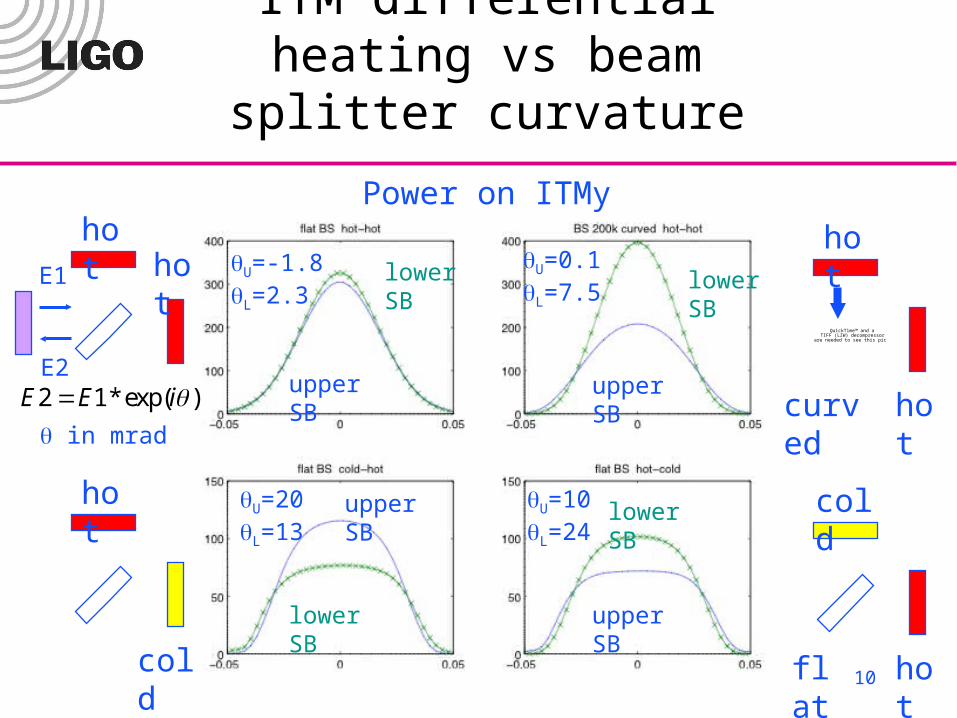
ITM differential heating vs beam splitter curvature
hothot
hot
cold
hot
hotcurved
cold
hotflat
lower SB
upper SB
lower SB
upper SB
lower SB
upper SB
lower SB
upper SB
QuickTime™ and aTIFF (LZW) decompressor
are needed to see this picture.
Power on ITMy
U=-1.8L=2.3
U=0.1L=7.5
U=10L=24
U=20L=13
E1
E2E2 E1* exp(i )
in mrad

LSC - Aug. 18, 2004 11
Gaussianity of CR & SBs
hot
hotflat
hot
coldflat
hot
hotcurved
cold
hotflat
QuickTime™ and aTIFF (LZW) decompressor
are needed to see this picture.
Power on Symmetric port : log(power) vs x2
CR
lowerupper + +
xy
5cm

LSC - Aug. 18, 2004 12
SB gain vs Gaussian heating with curved BS
powerX,Y for common heatingpowerX for differential heating
lower SB
upper SB
(power ITMx, power ITMy)
common heating
differential heating
ITMy 40mW
ITMy 60mW
Flat BS

LSC - Aug. 18, 2004 13
SB gain vs annular heatingR
ecyc
ling
gai
n
60mWGaussianOn both
Upper SB Lower SB Flat BS
200km BS
ITMy annular heatingITMx annular heating
200 mW-200 mW

LSC - Aug. 18, 2004 14
FFT vs LSC lock
lower SB upper SB
FFT lock LSC lock
FFT LSC
CR 0.3 -1.9
SB+ -0.6 -2.3
SB- 7.2 5.1
Spob -0.57i -0.57i
CR 0.2 -8
SB+ 4.9 -1.2
SB- 11.8 5.1
Spob -0.48i -0.50i
sym
met
ric
diff
eren
tial
0.96-0.96 1.10-0.96
n(ITMx)-n(ITMy)
SB becomes moresymmetric

LSC - Aug. 18, 2004 15
Dark Port sideband profile- after LSC lock -
upper SB
lower SB
No phase mapSymmetric heating
With phase mapSymmetric heating
With phase mapDifferential heating
200k BS curvature