Embed Size (px)
Citation preview
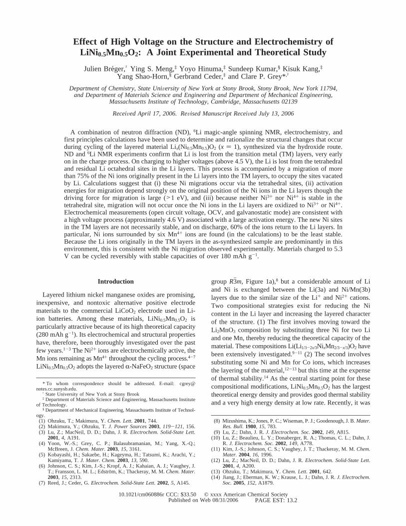
Effect of High Voltage on the Structure and Electrochemistry ofLiNi 0.5Mn0.5O2: A Joint Experimental and Theoretical Study
Julien Breger,† Ying S. Meng,‡ Yoyo Hinuma,‡ Sundeep Kumar,§ Kisuk Kang,‡Yang Shao-Horn,§ Gerbrand Ceder,‡ and Clare P. Grey*,†
Department of Chemistry, State UniVersity of New York at Stony Brook, Stony Brook, New York 11794,and Department of Materials Science and Engineering and Department of Mechanical Engineering,
Massachusetts Institute of Technology, Cambridge, Massachusetts 02139
ReceiVed April 17, 2006. ReVised Manuscript ReceiVed July 13, 2006
A combination of neutron diffraction (ND),6Li magic-angle spinning NMR, electrochemistry, andfirst principles calculations have been used to determine and rationalize the structural changes that occurduring cycling of the layered material Lix(Ni0.5Mn0.5)O2 (x ) 1), synthesized via the hydroxide route.ND and6Li NMR experiments confirm that Li is lost from the transition metal (TM) layers, very earlyon in the charge process. On charging to higher voltages (above 4.5 V), the Li is lost from the tetrahedraland residual Li octahedral sites in the Li layers. This process is accompanied by a migration of morethan 75% of the Ni ions originally present in the Li layers into the TM layers, to occupy the sites vacatedby Li. Calculations suggest that (i) these Ni migrations occur via the tetrahedral sites, (ii) activationenergies for migration depend strongly on the original position of the Ni ions in the Li layers though thedriving force for migration is large (>1 eV), and (iii) because neither Ni3+ nor Ni4+ is stable in thetetrahedral site, migration will not occur once the Ni ions in the Li layers are oxidized to Ni3+ or Ni4+.Electrochemical measurements (open circuit voltage, OCV, and galvanostatic mode) are consistent witha high voltage process (approximately 4.6 V) associated with a large activation energy. The new Ni sitesin the TM layers are not necessarily stable, and on discharge, 60% of the ions return to the Li layers. Inparticular, Ni ions surrounded by six Mn4+ ions are found (in the calculations) to be the least stable.Because the Li ions originally in the TM layers in the as-synthesized sample are predominantly in thisenvironment, this is consistent with the Ni migration observed experimentally. Materials charged to 5.3V can be cycled reversibly with stable capacities of over 180 mAh g-1.
Introduction
Layered lithium nickel manganese oxides are promising,inexpensive, and nontoxic alternative positive electrodematerials to the commercial LiCoO2 electrode used in Li-ion batteries. Among these materials, LiNi0.5Mn0.5O2 isparticularly attractive because of its high theoretical capacity(280 mAh g-1). Its electrochemical and structural propertieshave, therefore, been thoroughly investigated over the pastfew years.1-3 The Ni2+ ions are electrochemically active, theMn ions remaining as Mn4+ throughout the cycling process.4-7
LiNi 0.5Mn0.5O2 adopts the layeredR-NaFeO2 structure (space
group R3hm, Figure 1a),8 but a considerable amount of Liand Ni is exchanged between the Li(3a) and Ni/Mn(3b)layers due to the similar size of the Li+ and Ni2+ cations.Two compositional strategies exist for reducing the Nicontent in the Li layer and increasing the layered characterof the structure. (1) The first involves moving toward theLi2MnO3 composition by substituting three Ni for two Liand one Mn, thereby reducing the theoretical capacity of thematerial. These compositions Li(Li1/3-2x/3NixMn2/3-x/3)O2 havebeen extensively investigated.9-11 (2) The second involvessubstituting some Ni and Mn for Co ions, which increasesthe layering of the material,12-13 but this time at the expenseof thermal stability.14 As the central starting point for thesecompositional modifications, LiNi0.5Mn0.5O2 has the largesttheoretical energy density and provides good thermal stabilityand a very high energy density at low rate. Recently, it was
* To whom correspondence should be addressed. E-mail: [email protected].
† State University of New York at Stony Brook‡ Department of Materials Science and Engineering, Massachusetts Institute
of Technology.§ Department of Mechanical Engineering, Massachusetts Institute of Technol-
ogy.(1) Ohzuku, T.; Makimura, Y.Chem. Lett.2001, 744.(2) Makimura, Y.; Ohzuku, T.J. Power Sources2003, 119-121, 156.(3) Lu, Z.; MacNeil, D. D.; Dahn, J. R.Electrochem. Solid-State Lett.
2001, 4, A191.(4) Yoon, W.-S.; Grey, C. P.; Balasubramanian, M.; Yang, X.-Q.;
McBreen, J. Chem. Mater.2003, 15, 3161.(5) Kobayashi, H.; Sakaebe, H.; Kageyma, H.; Tatsumi, K.; Arachi, Y.;
Kamiyama, T.J. Mater. Chem.2003, 13, 590.(6) Johnson, C. S.; Kim, J.-S.; Kropf, A. J.; Kahaian, A. J.; Vaughey, J.
T.; Fransson, L. M. L.; Edstro¨m, K.; Thackeray, M. M.Chem. Mater.2003, 15, 2313.
(7) Reed, J.; Ceder, G.Electrochem. Solid-State Lett.2002, 5, A145.
(8) Mizushima, K.; Jones, P. C.; Wiseman, P. J.; Goodenough, J. B.Mater.Res. Bull.1980, 15, 783.
(9) Lu, Z.; Dahn, J. R.J. Electrochem. Soc.2002, 149, A815.(10) Lu, Z.; Beaulieu, L. Y.; Donaberger, R. A.; Thomas, C. L.; Dahn, J.
R. J. Electrochem. Soc.2002, 149, A778.(11) Kim, J.-S.; Johnson, C. S.; Vaughey, J. T.; Thackeray, M. M.Chem.
Mater. 2004, 16, 1996.(12) Lu, Z.; MacNeil, D. D.; Dahn, J. R.Electrochem. Solid-State Lett.
2001, 4, A200.(13) Ohzuku, T.; Makimura, Y.Chem. Lett.2001, 642.(14) Jiang, J.; Eberman, K. W.; Krause, L. J.; Dahn, J. R.J. Electrochem.
Soc.2005, 152, A1879.
10.1021/cm060886r CCC: $33.50 © xxxx American Chemical SocietyPAGE EST: 13.2Published on Web 08/31/2006
further shown that a more layered version of LiNi0.5Mn0.5O2
can rival the rate capability of the Co-substituted materials.15
The objective of this work is to investigate in detail thedelithiation process of LiNi0.5Mn0.5O2 and characterize anychanges in the transition metal (TM) configuration that takeplace upon cycling.
The Li/Ni disorder in samples synthesized by regular solid-state routes plays a central role in determining the structureof LiNi 0.5Mn0.5O2. Li magic-angle spinning (MAS) NMRexperiments found Li+ ions in the TM layers of LiNi0.5-Mn0.5O2, surrounded predominantly by five to six Mn4+ ionsresembling the environment in Li2MnO3,16,17while X-ray andneutron diffraction (ND) studies by Lu et al.3,9,10 indicated
partial exchange (8-10% of the Ni ions) between the Niand the Li ions in the TM and Li layers. The low energy ofthe LiMn6 honeycomb motif present in Li2MnO3 wassuggested to provide a driving force for the Li+/Ni2+
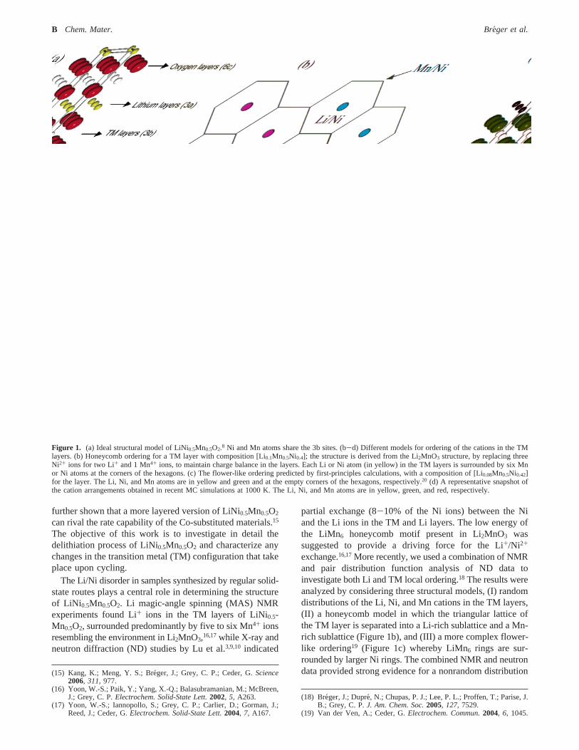
exchange.16,17More recently, we used a combination of NMRand pair distribution function analysis of ND data toinvestigate both Li and TM local ordering.18 The results wereanalyzed by considering three structural models, (I) randomdistributions of the Li, Ni, and Mn cations in the TM layers,(II) a honeycomb model in which the triangular lattice ofthe TM layer is separated into a Li-rich sublattice and a Mn-rich sublattice (Figure 1b), and (III) a more complex flower-like ordering19 (Figure 1c) whereby LiMn6 rings are sur-rounded by larger Ni rings. The combined NMR and neutrondata provided strong evidence for a nonrandom distribution(15) Kang, K.; Meng, Y. S.; Bre´ger, J.; Grey, C. P.; Ceder, G.Science
2006, 311, 977.(16) Yoon, W.-S.; Paik, Y.; Yang, X.-Q.; Balasubramanian, M.; McBreen,
J.; Grey, C. P.Electrochem. Solid-State Lett.2002, 5, A263.(17) Yoon, W.-S.; Iannopollo, S.; Grey, C. P.; Carlier, D.; Gorman, J.;
Reed, J.; Ceder, G.Electrochem. Solid-State Lett.2004, 7, A167.
(18) Breger, J.; Dupre´, N.; Chupas, P. J.; Lee, P. L.; Proffen, T.; Parise, J.B.; Grey, C. P.J. Am. Chem. Soc.2005, 127, 7529.
(19) Van der Ven, A.; Ceder, G.Electrochem. Commun.2004, 6, 1045.
Figure 1. (a) Ideal structural model of LiNi0.5Mn0.5O2.8 Ni and Mn atoms share the 3b sites. (b-d) Different models for ordering of the cations in the TMlayers. (b) Honeycomb ordering for a TM layer with composition [Li0.1Mn0.5Ni0.4]; the structure is derived from the Li2MnO3 structure, by replacing threeNi2+ ions for two Li+ and 1 Mn4+ ions, to maintain charge balance in the layers. Each Li or Ni atom (in yellow) in the TM layers is surrounded by six Mnor Ni atoms at the corners of the hexagons. (c) The flower-like ordering predicted by first-principles calculations, with a composition of [Li0.08Mn0.5Ni0.42]for the layer. The Li, Ni, and Mn atoms are in yellow and green and at the empty corners of the hexagons, respectively.20 (d) A representative snapshot ofthe cation arrangements obtained in recent MC simulations at 1000 K. The Li, Ni, and Mn atoms are in yellow, green, and red, respectively.
B Chem. Mater. Breger et al.

of the cations, with much stronger Li-Ni avoidance thanpredicted by simple honeycomb ordering, the resultingstructure more resembling a partially disordered “flower”arrangement. Recent Monte Carlo (MC) simulations byHinuma et al.20 (Figure 1d) are in very good agreement withthis model, indicating that materials produced via high-temperature routes show considerable disorder over thatpredicted from ground-state structures but still retain someof the key structural features of the flower ordering, namely,Li-Ni avoidance.
While these previous studies have improved our under-standing of the pristine structure, less clarity exists as to thestructural changes that occur upon delithiation of the material.Makimura21 has shown that the deintercalated material Lix-Ni0.5Mn0.5O2, x < 1, maintains the parent hexagonalR3hmcell throughout, while Arachi et al. have observed a transitionfrom the hexagonalR3hm cell to a monoclinicC2/m cellbetweenx ) 0.7 andx ) 0.8.22 These authors also foundthat a fraction of the octahedral Li and Ni atoms migrate totetrahedral sites upon charge.22,23 Previous ex situ NMRexperiments on charged samples have shown that thestructural changes are even more complex. The Li locatedin the TM layers is removed very early on in the chargeprocess:16 approximately 50% of these ions have left the TMlayers forx ) 0.7, and they have essentially all disappearedfor x ) 0.4.16 These results are in qualitative agreementswith predictions from first principles calculations made forthe perfect flower structure, which show that the Li ionsmigrate into the tetrahedral sites that share faces with thevacated octahedral site in the TM layers very early on inthe charge process.19 The occupation of tetrahedral sites isan obvious consequence of the Li extraction from the TMlayer. While in a perfectly layered material, all tetrahedralsites share at least one face with the octahedral cation in theTM layers, a vacancy in the TM layer creates two emptytetrahedral sites in the Li layers above and below the TMlayer. Both these sites can be occupied by Li, creating Lidumbbells if no nearest neighbor tetrahedral sites are alreadyoccupied (Figure 2).
Despite much work on this system, a number of issues,which are pivotal to the understanding of the functioning ofthese electrode materials, are poorly understood. For ex-ample, while the first principles calculations predict that theremay be a high voltage process involving removal of thetetrahedral Li ions19 and the diffraction results suggest thatNi may not always remain in its original site,22 the detailsof why and when the Ni ions move are not known.Furthermore, our recent results, on a layered material withessentially no Li/Ni exchange and excellent high rateperformance, shows that the Ni populations in the Li layersplay a key role in controlling the slab spacing and, hence,the Li-ion conductivity in the Li layers.15 The aim of thework presented in this paper is to combine results from
neutron and X-ray diffraction (XRD),6Li MAS NMRspectroscopy, and calculations to determine and then ratio-nalize the structural changes that occur on charging LixNi0.5-Mn0.5O2. The effect of charging to high voltages, to establishwhether the tetrahedral Li ions can indeed be removed, andthe consequent effect of this on the structure are explored.
Materials and Methods
Sample Preparation.LiNi 0.5Mn0.5O2 powders were prepared bythe mixed hydroxide method.3 A 50 mL aqueous solution ofstoichiometric amounts of TM nitrates was prepared and slowlydripped (1-2 h) into 400 mL of a stirred solution of LiOH usinga burette, yielding a precipitation of M(OH)2, where M) Mn andNi, with a homogeneous cation distribution. The dried precipitatewas mixed with Li(OH)‚H2O in stoichiometric proportions. Themixture was then heated in air at 480°C for 12 h, annealed at 900°C or 1000°C for another 12 h, and quenched between two copperplates. The samples were prepared with6Li(OH)‚H2O (CambridgeIsotopes, 90-95%) for6Li MAS NMR measurements to maximizethe signal/noise ratio and acquisition time and with7Li(OH)‚H2O(Aldrich, >97%) for ND experiments to minimize absorption fromthe 6Li nuclei.
Electrochemistry. For the 6Li MAS NMR experiments, syn-chrotron XRD, and cycling experiments, cathodes were preparedby mixing 80 wt % of active material (6LiNi 0.5Mn0.5O2), 10 wt %of acetylene black as an electronic conductor, and 10 wt % of poly-(vinylidene fluoride) binder inN-methyl pyrrolidone (NMP). Theslurry was deposited on an aluminum foil and dried at 80°C untilthe solvent had evaporated completely. Coin cells (CR2032, HohsenCorp.) were assembled in an argon-filled glove box. Each cellcontains typically about 15 mg of active material, separated froma Li foil ( 6Li foil was when preparing the NMR samples) by twopieces of Celgard separator (Celgard, Inc., U.S.A.). A 1 M solutionof LiPF6 in ethylene carbonate/dimethyl carbonate (1:1) has been
(20) Hinuma, Y.; Meng, Y. S.; Kisuk, K.; Ceder, G. To be published.(21) Makimura, Y. Ph.D. Thesis, Osaka City University, 2003.(22) Arachi, Y.; Koabayashi, H.; Emura, S.; Nakata, Y.; Tanaka, M.; Asai,
T.; Sakaebe, H; Tatsumi, K.; Kageyama, H.Solid State Ionics2005,176, 895.
(23) Kobayashi, H.; Arachi, Y.; Kageyama, H.; Tatsumi, K.J. Mater. Chem.2004, 14, 40.
Figure 2. Li-Li dumbbell formed from a Li vacancy in the TM layers(LiTM
V) and two adjacent tetrahedral Li ions t1 above and below the TMlayer. Li-Ni dumbbells are formed from two adjacent tetrahedral Ni andLi ions. t2 is the tetrahedral site adjacent to the t1 site in the same plane.
LiNi0.5Mn0.5O2 ND, NMR, and First Principles Study Chem. Mater.C
used as the electrolyte. Electrochemical experiments were carriedout on a battery cycler (Arbin Instruments, College Station, TX)in galvanostatic mode at aC/20 rate.
Slightly different electrode mixtures were used to prepare cycledsamples suitable for the ND experiments, to reduce the total protoncontent of these electrodes, to minimize absorption problems. A300 mg mixture containing 90% of active material (7LiNi 0.5Mn0.5O2)and 10% of graphite (Timrex KS44) was deposited on an aluminumplate and dried at 80°C until complete evaporation of NMP; nobinder was used. Swagelok-type cells were assembled in an argon-filled glove box. They were separated from a lithium foil by twosheets of fiberglass filters. The whole assembly was soaked in theelectrolyte, an ethylene carbonate/dimethyl carbonate (1:1) solutionof LiPF6 (1 M). Electrochemical experiments were carried out at aC/200 rate. The samples were washed with deuterated acetonebefore ND experiments, again to reduce proton contents in thesamples. Some of these samples were analyzed by inductivelycoupled plasma-optical emission spectroscopy (ICP-OES) byGalbraith, to compare the Li contents with those estimated fromthe electrochemical data.
ND. ND experiments were performed on the General MaterialsDiffractometer (GEM) instrument at ISIS (Didcot, U.K.), on theGeneral Purpose Powder Diffractometer (GPPD) instrument at theIntense Pulse Neutron Source (IPNS, Argonne National Laboratory),and on the Neutron Powder Diffractometer (NPDF) instrument atthe Los Alamos Neutron Science Center (LANSCE, Los AlamosNational Laboratory). The samples (from 300 mg to 1 g) werepacked into 0.25 in. inside diameter thin-walled vanadium cans ina helium-filled glovebox.
In Situ XRD Diffraction. Experiments were performed atbeamline X7A at the National Synchrotron Light Source (NSLS)located at Brookhaven National Laboratory, using a cell designidentical to that described elsewhere.24 Synchrotron radiation witha wavelength of 0.6482 Å and a step size of 0.25° every 5 s wereemployed.
MAS NMR Spectroscopy. The 6Li MAS NMR experimentswere performed with a double-resonance 2 mm probe, built bySamoson and co-workers,25 on a CMX-200 spectrometer using amagnetic field of 4.7 T. The spectra were collected at an operatingfrequency of 29.46 MHz. A spinning frequency between 35 and40 kHz and a rotor-synchronized spin-echo sequence (90°-τ-180°-τ-acq) were used to acquire the spectra.π/2 pulses of 3.5µs were used, with recycle delay times of 0.2 s. All the NMR spectrawere referenced to a 1 M6LiCl solution, at 0 ppm, and were scaledaccording to the acquisition number and the sample weight in therotor.
Calculations Methodology.All energies are calculated with thespin-polarized generalized gradient approximation to density func-tional theory (DFT), using a plane-wave basis set and the projector-augmented wave method as implemented in the Vienna ab initiosimulation package (VASP). A plane-wave basis with a kineticenergy cutoff of 370 eV was used. The reciprocal-spacek-pointgrids between 3× 3 × 3 and 7× 7 × 7 were used depending onthe size of the supercell considered. Structures were fully relaxed.The +U correction term in the Dudarev scheme26 was used withU ) 5.96 eV for Ni andU ) 5 eV for Mn. This+U scheme correctsfor the self-interaction in the TMd orbitals and has been shown toimprove the prediction of voltages27 and phase stability.28 The local
density approximation (LDA)+U approach was chosen for thec-lattice parameter calculation as it more accurately treats the Vander Waals interactions across the empty Li slab at the end of chargeand has previously been shown to give qualitatively more correctvariations in lattice parameter with Li concentration.29
Results and Analysis of the Experimental Data andCalculations
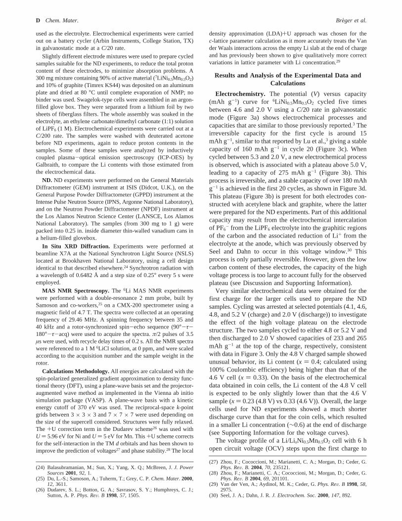
Electrochemistry. The potential (V) versus capacity(mAh g-1) curve for 6LiNi 0.5Mn0.5O2 cycled five timesbetween 4.6 and 2.0 V using aC/20 rate in galvanostaticmode (Figure 3a) shows electrochemical processes andcapacities that are similar to those previously reported.3 Theirreversible capacity for the first cycle is around 15mAh g-1, similar to that reported by Lu et al.,3 giving a stablecapacity of 160 mAh g-1 in cycle 20 (Figure 3c). Whencycled between 5.3 and 2.0 V, a new electrochemical processis observed, which is associated with a plateau above 5.0 V,leading to a capacity of 275 mAh g-1 (Figure 3b). Thisprocess is irreversible, and a stable capacity of over 180 mAhg-1 is achieved in the first 20 cycles, as shown in Figure 3d.This plateau (Figure 3b) is present for both electrodes con-structed with acetylene black and graphite, where the latterwere prepared for the ND experiments. Part of this additionalcapacity may result from the electrochemical intercalationof PF6
- from the LiPF6 electrolyte into the graphitic regionsof the carbon and the associated reduction of Li+ from theelectrolyte at the anode, which was previously observed bySeel and Dahn to occur in this voltage window.30 Thisprocess is only partially reversible. However, given the lowcarbon content of these electrodes, the capacity of the highvoltage process is too large to account fully for the observedplateau (see Discussion and Supporting Information).
Very similar electrochemical data were obtained for thefirst charge for the larger cells used to prepare the NDsamples. Cycling was arrested at selected potentials (4.1, 4.6,4.8, and 5.2 V (charge) and 2.0 V (discharge)) to investigatethe effect of the high voltage plateau on the electrodestructure. The two samples cycled to either 4.8 or 5.2 V andthen discharged to 2.0 V showed capacities of 233 and 265mAh g-1 at the top of the charge, respectively, consistentwith data in Figure 3. Only the 4.8 V charged sample showedunusual behavior, its Li content (x ) 0.4; calculated using100% Coulombic efficiency) being higher than that of the4.6 V cell (x ) 0.33). On the basis of the electrochemicaldata obtained in coin cells, the Li content of the 4.8 V cellis expected to be only slightly lower than that the 4.6 Vsample (x ) 0.23 (4.8 V) vs 0.33 (4.6 V)). Overall, the largecells used for ND experiments showed a much shorterdischarge curve than that for the coin cells, which resultedin a smaller Li concentration (∼0.6) at the end of discharge(see Supporting Information for the voltage curves).
The voltage profile of a Li/LixNi0.5Mn0.5O2 cell with 6 hopen circuit voltage (OCV) steps upon the first charge to
(24) Balasubramanian, M.; Sun, X.; Yang, X. Q.; McBreen, J.J. PowerSources2001, 92, 1.
(25) Du, L.-S.; Samoson, A.; Tuherm, T.; Grey, C. P.Chem. Mater.2000,12, 3611.
(26) Dudarev, S. L.; Botton, G. A.; Savrasov, S. Y.; Humphreys, C. J.;Sutton, A. P.Phys. ReV. B 1998, 57, 1505.
(27) Zhou, F.; Cococcioni, M.; Marianetti, C. A.; Morgan, D.; Ceder, G.Phys. ReV. B. 2004, 70, 235121.
(28) Zhou, F.; Marianetti, C. A.; Cococcioni, M.; Morgan, D.; Ceder, G.Phys. ReV. B 2004, 69, 201101.
(29) Van der Ven, A.; Aydinol, M. K.; Ceder, G.Phys. ReV. B 1998, 58,2975.
(30) Seel, J. A.; Dahn, J. R.J. Electrochem. Soc.2000, 147, 892.
D Chem. Mater. Breger et al.
5.3 V under a current density corresponding toC/50 consistsof two relatively flat regions at∼3.8 V and∼4.5 V and onesloping region in between. Notably, the OCV values flattenat 4.54 V at charging voltages higher than 4.90 V. This datais compared later with predictions from theory in Figure 9.
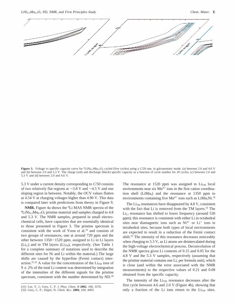
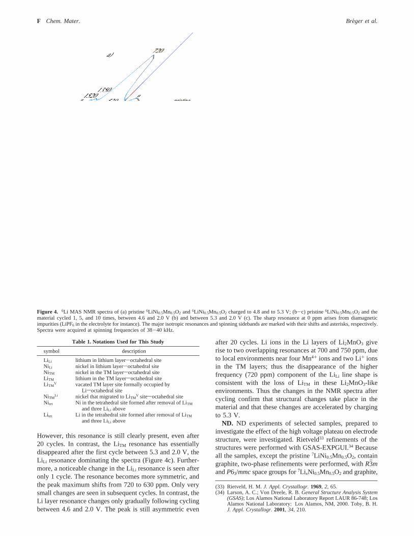
NMR. Figure 4a shows the6Li MAS NMR spectra of the6LiNi 0.5Mn0.5O2 pristine material and samples charged to 4.8and 5.3 V. The NMR samples, prepared in small electro-chemical cells, have capacities that are essentially identicalto those presented in Figure 3. The pristine spectrum isconsistent with the work of Yoon et al.16 and consists oftwo groups of resonances, one at around 720 ppm and theother between 1350-1520 ppm, assigned to Li in Li layers(Li Li) and in TM layers (LiTM), respectively. (See Table 1for a complete summary of notations used to describe thedifferent sites for Ni and Li within the material.) The largeshifts are caused by the hyperfine (Fermi contact) inter-action.31,32A value for the concentration of the LiTM ions of9 ( 2% of the total Li content was determined by integrationof the intensities of the different signals for the pristinespectrum, consistent with the number determined by ND.18
The resonance at 1520 ppm was assigned to LiTM localenvironments near six Mn4+ ions in the first cation coordina-tion shell (LiMn6) and the resonance at 1350 ppm toenvironments containing five Mn4+ ions such as LiMn5Ni.16
The LiTM resonances have disappeared by 4.8 V, consistentwith the fact that Li is removed from the TM layers.16 TheLiLi resonance has shifted to lower frequency (around 530ppm); this resonance is consistent with either Li in octahedralsites near diamagnetic ions such as Ni4+ or Li+ ions intetrahedral sites, because both types of local environmentsare expected to result in a reduction of the Fermi contactshift.32 The intensity of this resonance decreases noticeablywhen charging to 5.3 V, as Li atoms are deintercalated duringthe high-voltage electrochemical process. Deconvolution ofthe NMR spectra gives Li contents of 0.15 and 0.05 for the4.8 V and the 5.3 V samples, respectively (assuming thatthe pristine material contains one Li, per formula unit), whichis close (and within the error associated with the NMRmeasurements) to the respective values of 0.21 and 0.08obtained from the specific capacity.
The intensity of the LiTM resonance decreases after thefirst cycle between 4.6 and 2.0 V (Figure 4b), showing thatonly a fraction of the Li ions return to the LiTM sites.
(31) Lee, Y. J.; Grey, C. P.J. Phys. Chem. B2002, 106, 3576.(32) Grey, C. P.; Dupre´, N. Chem. ReV. 2004, 104, 4493.
Figure 3. Voltage vs specific capacity curve for6LiNi 0.5Mn0.5O2 cycled (five cycles) using aC/20 rate, in galvanostatic mode, (a) between 2.0 and 4.6 Vand (b) between 2.0 and 5.3 V. The charge (red) and discharge (black) specific capacity as a function of cycle number for 20 cycles, (c) between 2.0 and5.3 V and (d) between 2.0 and 4.6 V.
LiNi0.5Mn0.5O2 ND, NMR, and First Principles Study Chem. Mater.E
However, this resonance is still clearly present, even after20 cycles. In contrast, the LiTM resonance has essentiallydisappeared after the first cycle between 5.3 and 2.0 V, theLi Li resonance dominating the spectra (Figure 4c). Further-more, a noticeable change in the LiLi resonance is seen afteronly 1 cycle. The resonance becomes more symmetric, andthe peak maximum shifts from 720 to 630 ppm. Only verysmall changes are seen in subsequent cycles. In contrast, theLi layer resonance changes only gradually following cyclingbetween 4.6 and 2.0 V. The peak is still asymmetric even
after 20 cycles. Li ions in the Li layers of Li2MnO3 giverise to two overlapping resonances at 700 and 750 ppm, dueto local environments near four Mn4+ ions and two Li+ ionsin the TM layers; thus the disappearance of the higherfrequency (720 ppm) component of the LiLi line shape isconsistent with the loss of LiTM in these Li2MnO3-likeenvironments. Thus the changes in the NMR spectra aftercycling confirm that structural changes take place in thematerial and that these changes are accelerated by chargingto 5.3 V.
ND. ND experiments of selected samples, prepared toinvestigate the effect of the high voltage plateau on electrodestructure, were investigated. Rietveld33 refinements of thestructures were performed with GSAS-EXPGUI.34 Becauseall the samples, except the pristine7LiNi 0.5Mn0.5O2, containgraphite, two-phase refinements were performed, withR3hmandP63/mmcspace groups for7Li xNi0.5Mn0.5O2 and graphite,
(33) Rietveld, H. M.J. Appl. Crystallogr.1969, 2, 65.(34) Larson, A. C.; Von Dreele, R. B.General Structure Analysis System
(GSAS); Los Alamos National Laboratory Report LAUR 86-748; LosAlamos National Laboratory: Los Alamos, NM, 2000. Toby, B. H.J. Appl. Crystallogr.2001, 34, 210.
Figure 4. 6Li MAS NMR spectra of (a) pristine6LiNi 0.5Mn0.5O2 and6LiNi 0.5Mn0.5O2 charged to 4.8 and to 5.3 V; (b-c) pristine6LiNi 0.5Mn0.5O2 and thematerial cycled 1, 5, and 10 times, between 4.6 and 2.0 V (b) and between 5.3 and 2.0 V (c). The sharp resonance at 0 ppm arises from diamagneticimpurities (LiPF6 in the electrolyte for instance). The major isotropic resonances and spinning sidebands are marked with their shifts and asterisks, respectively.Spectra were acquired at spinning frequencies of 38-40 kHz.
Table 1. Notations Used for This Study
symbol description
LiLi lithium in lithium layersoctahedral siteNiLi nickel in lithium layersoctahedral siteNiTM nickel in the TM layersoctahedral siteLiTM lithium in the TM layersoctahedral siteLiTM
V vacated TM layer site formally occupied byLisoctahedral site
NiTMLi nickel that migrated to LiTM
V sitesoctahedral siteNitet Ni in the tetrahedral site formed after removal of LiTM
and three LiLi aboveLi tet Li in the tetrahedral site formed after removal of LiTM
and three LiLi above
F Chem. Mater. Breger et al.
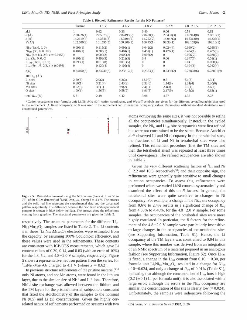
respectively. The structural parameters for the different7Li x-Ni0.5Mn0.5O2 samples are listed in Table 2. The Li contentsx in these7Li xNi0.5Mn0.5O2 electrodes were estimated fromthe capacity, by assuming 100% Coulombic efficiency, andthese values were used in the refinements. These contentsare consistent with ICP-OES measurements, which gave Licontent values of 0.30, 0.14, and 0.63 (with an error of 10%)for the 4.8, 5.2, and 4.8-2.0 V samples, respectively. Figure5 shows a representative neutron pattern from the series, for7LiNi 0.5Mn0.5O2 charged to 4.1 V (wherex ) 0.62).
In previous structure refinements of the pristine material,9,10
only Ni atoms, and not Mn atoms, were found in the lithiumlayer, due to the similar size of Ni2+ and Li+ ions. Therefore,Ni/Li site exchange was allowed between the lithium andthe TM layers for the pristine material, subject to a constraintthat fixed the stoichiometry of the samples to the nominalNi (0.5) and Li (x) concentrations. Given the highly cor-related nature of refinements performed on systems with two
atoms occupying the same sites, it was not possible to refineall the occupancies simultaneously. Instead, in the cycledsamples, the NiLi and LiTM site occupancies were first refinedbut were not constrained to be the same. Because Arachi etal.22 observed Li and Ni occupancy in the tetrahedral sites,the fractions of Li and Ni in tetrahedral sites were alsorefined. This refinement procedure (first the TM sites andthen the tetrahedral sites) was repeated at least three timesuntil convergence. The refined occupancies are also shownin Table 2.
Given the very different scattering factors of7Li and Ni(-2.2 and 10.3, respectively35) and their opposite sign, therefinements were generally quite sensitive to small changesin cation occupancies. To assess this, refinements wereperformed where we varied Li/Ni contents systematically andexamined the effect of this onR factors. In general, thetetrahedral sites were quite sensitive to changes in Nioccupancy. For example, a change in the Nitet site occupancyfrom 0.6% to 2.4% results in a significant change ofRwp
from 4.35% to 4.46%, for the 4.8-2.0 V sample. For somesamples, the occupancies of the octahedral sites were morehighly correlated. In particular, theR factors for the refine-ment of the 4.8-2.0 V sample were particularly insensitiveto large changes in the occupancies of the octahedral sites(see Supporting Information, Table S1). Hence, the Lioccupancy of the TM layers was constrained to 0.04 in thissample, where this number was derived from an integrationof an NMR spectrum of a material prepared in an analogousfashion (see Supporting Information, Figure S2). Once LiTM
is fixed, a change in the Litet content from 0.10- 0.30, performula unit LixNi0.5Mn0.5O2, resulted in a change for Nitet
of 0-0.024, and only a change ofRwp of 0.01% (Table S1),indicating that although the concentration of Litet ions is high(0.2 ((0.1) Li per formula unit), it is also associated with alarge error; although the errors in the Nitet occupancy aresimilar, the concentration of this site is clearly low (>0.024).Unfortunately, the samples were radioactive following the
(35) Sears, V. F.Neutron News 31992, 3, 26.
Table 2. Rietveld Refinement Results for the ND Patternsa
pristine 4.1 V 4.6 V 4.8 V 5.2 V 4.8-2.0 V 5.2-2.0 V
xLi 1 0.62 0.33 0.40 0.06 0.58 0.62a (Å) 2.88226(4) 2.85575(8) 2.84499(5) 2.8488(1) 2.8431(3) 2.86914(8) 2.8818(1)c (Å) 14.2619(4) 14.3846(8) 14.3104(5) 14.292(2) 14.047(3) 14.3313(9) 14.335(1)V (Å3) 102.606(3) 101.595(5) 100.309(3) 100.45(1) 98.33(1) 102.169(6) 103.10(1)
NiLi (3a; 0, 0, 0) 0.099(1) 0.115(2) 0.096(1) 0.042(2) 0.024(4) 0.060(2) 0.058(3)NiTM (3b; 0, 0, 1/2) 0.401(1) 0.385(1) 0.404(1) 0.452(1) 0.476(4) 0.434(1) 0.405(3)Nitet (6c; 1/3, 2/3,z≈ 0.0456) 0 0.000(2) 0.000(2) 0.006(2) 0 0.006(2) 0.038(2)Li Li (3a; 0, 0, 0) 0.901(1) 0.498(5) 0.212(5) 0.4 0.06 0.347(7) 0.58(1)LiTM (3b; 0, 0, 1/2) 0.099(1) 0.013(8) 0.016(5) 0 0 0.04 0.000(4)Li tet (6c; 1/3, 2/3,z≈ 0.0456) 0 0.120(4) 0.102(4) 0 0 0.194(6) 0.042(4)
z(O) 0.24160(3) 0.23740(6) 0.23617(5) 0.2373(1) 0.2395(2) 0.23828(6) 0.23801(9)
100Uiso (Å2)Li sites 2.60(5) 2.9(2) 4.2(3) 13.0(9) 0.7 6.1(3) 1.3(1)Ni sites 0.60(1) 3.21(4) 2.43(3) 2.33(6) 1.14(8) 2.31(4) 2.30(6)Mn sites 0.62(3) 3.6(1) 9.9(2) 2.4(1) 2.4(3) 2.3(1) 2.6(2)O sites 1.00(1) 1.56(3) 0.58(2) 1.91(5) 2.17(9) 0.45(2) 0.63(1)
totalRwp (%) 5.81 2.49 4.42 3.06 4.27 4.35 2.78
a Cation occupancies (per formula unit LixNi0.5Mn0.5O2), cation coordinates, and Wycoff symbols are given for the different crystallographic sites usedin the refinement. A fixed occupancy of 0 was used if the refinement led to negative occupancy values. Parameters without standard deviations wereconstrained parameters.
Figure 5. Rietveld refinement using the ND pattern (bank 4, from 50 to75°, of the GEM detector) of7LiNi 0.5Mn0.5O2 charged to 4.1 V. The crossesand the solid red line represent the experimental data and the calculatedpattern, respectively. The difference between the calculated and experimentalpatterns is shown in blue below the data. The arrows show the reflectionscoming from graphite. The structural parameters are given in Table 2.
LiNi0.5Mn0.5O2 ND, NMR, and First Principles Study Chem. Mater.G

ND experiments and joint X-ray-neutron experiments couldnot be performed on the same samples.
The fraction of both LiTM ions decreases rapidly withincreasing state of charge (Figure 6), while the NiLi oc-cupancy drops noticeably only at high voltages. The LiTM
ions do not return to the TM layers if the sample is cycledbetween 5.2 and 2.0 V (Figure 6b), as confirmed by MASNMR (Figure 4c), while a small fraction of the NiLi doesreturn (Figure 6a). On the basis of this ND analysis, it isclear that noticeable structural changes do occur between4.6 and 5.2 V. These changes are at least partially irrevers-ible, as different cation occupancies are seen for the fullydischarged samples following charging to 4.8 and 5.2 V. TheNi occupancy in the tetrahedral sites is very small throughoutthe charging process, while the Li occupancy in thetetrahedral sites reaches a maximum at half-charge. Bothincrease when cycled once between 5.2 and 2.0 V. Thedifferences in the 4.6, 4.8, and 5.2 V samples are alsoapparent if thea and c parameters of these samples areconsidered (Figure 6e,f), the value of thec cell parameterdecreasing dramatically from 4.8 to 5.2 V, indicating thatthe layers collapse upon further deintercalation of theremaining lithium atoms.
Because Arachi et al.22 previously showed (by transmissionelectron microscopy and synchrotron XRD) that a second-order phase transition from hexagonal to monoclinic (C2/m) occurs during Li deintercalation of Li(NiMn)0.5O2, the
refinements were also attempted with theC2/mspace group.Patterns calculated with this space group contained additionalreflections that were absent in our experimental patterns.Furthermore, no reductions in theR factors, over thoseobserved with the space groupR3hm, were observed. Ourinability to detect a reduction in symmetry may be relatedto the higher resolution seen in synchrotron based experi-ments or slight differences in the samples.
In Situ XRD. In situ experiments were performed tofollow the changes in cell parameters as a function of Licontent. The changes in thea andc parameters (SupportingInformation, Figure S5, and inset in Figure 10) seen uponcharging to 4.8 V largely mirror those seen by ND, but incontrast to the ND results, thea and c parameters varysmoothly until full charge. These in situ results provideadditional evidence that structural changes do occur above4.6 V and that the capacity in this voltage range is not onlydue to side reactions involving the electrolyte.
First Principles Calculations.First principles calculationswere performed to predict and rationalize the structuralchanges that occur on cycling. Three aspects were investi-gated in particular: (1) the thermodynamic driving force forNi migration and the effect it has on the Li deintercalationvoltage, (2) the activation barriers for Ni migration in theLi layer and toward the vacancies in the TM layer, and (3)the influence of interlayer spacing on the stability of Ni ionsin the TM layers against migration into tetrahedral sites.
Figure 6. Evolution of parameters obtained from Rietveld refinements using ND data of pristine7LiNi 0.5Mn0.5O2 and7LiNi 0.5Mn0.5O2 charged to 4.1, 4.6,4.8, and 5.2 V and cycled once between 4.8 or 5.2 and 2.0 V. The solid line and the dotted lines represent the first charge and discharge, respectively.Evolution of the fractional occupancy of (a) Ni in Li layers; (b) Li in TM layers; and (c and d) Ni and Li in tetrahedral sites, respectively. The error barscorrespond to the maximum value of the standard errors obtained from Rietveld refinements. (e and f) Evolution of thec anda parameters, respectively.
H Chem. Mater. Breger et al.

Computations require periodic supercells and, hence, anordered arrangement of ions. These calculations were,therefore, performed using the previously proposed “flower”arrangement19 with a supercell of 12 formula units (Figure1c).
A. Ni and Li Rearrangements: Thermodynamic DriVingForces and Kinetic Barriers.To understand the thermody-namic driving forces acting upon the structure, we havecalculated the energies of three types of structural modifica-tions of the flower structure, as a function of Li composi-tion: (1) Li extraction with no Ni migration, (2) Li extractionwith migration of Ni from the Li layers, NiLi, into thetetrahedral sites, and (3) Li extraction with migration of NiLi
into a vacant LiTMV site (in the TM layers; see Table 1) to
become NiTMLi. We later discuss whether such Ni migration
is kinetically possible. The changes under scenario (1) werealready presented in a previous paper,19 and we include themhere for completeness. Figure 7 shows the correspondingenergies of Lix(Ni0.5Mn0.5)O2 as a function of Li content. Thequantity plotted is the energy difference between the mixedstate and a compositionally averaged combination of LiNi0.5-Mn0.5O2 and Ni0.5Mn0.5O2. Negative energies indicate thatthe intermediate compositions are stable, either as a solidsolution, or as ordered states. Delithiation under scenario 1(no Ni migration) involves the formation of Li/Li dumbbells(see Figure 2) around the LiTM
V site in TM layers, vacatedearly in the charge process. These states (triangles in Figure7) have the lowest energy at most Li compositions. Remark-ably, the structural configuration in which NiLi migrates fromthe Li layer into the TM layer (scenario 3) has the lowestenergy near the end of charge. The Li/Ni dumbbell config-uration (formed from one Nitet and one Litet ion; Figure 2,scenario 2) is never lowest in energy for the well-orderedflower structure used for these calculations. However, theenergy difference between tetrahedral Li/Ni and Li/Lidumbbells is very small (12-20 meV per LiMO2 formulaunit in thex ) 0.33-0.66 range), and less favorable referencepositions for NiLi in the pristine material (as would exist ina more disordered material) may lead to intermediate Li/Nidumbbell formation. The energy difference between the Li/
Li and the Li/Ni dumbbell can be rationalized on the basisof the oxidation states of the Ni ions. In this compositionrange, NiLi remains as 2+ and has a weak preference foroctahedral coordination over tetrahedral coordination, ac-cording to ligand field theory.36 Because of the way theflower ordering repeats along thec axis, dumbbell formationaround every LiTM
V results in occupied tetrahedra that shareedges within one layer. As a result, the repulsion betweenLi +/Ni2+ tetrahedra within the lithium slab space is strongerthan that of Li+/Li + tetrahedra and is responsible for theirenergy difference. Hence, it is to be expected that in moredisordered materials than the one used in our computations,where some NiLi is in a higher energy state and more isolatedLi/Ni dumbbells can form, some tetrahedral Ni will bepresent.
More interestingly, the structural configuration in whichNiLi has moved from the Li layer into the TM layer to fillthe LiTM
V site has the lowest energy near the end of charge,when the Li concentration is below 0.33. The driving forcefor this configuration is straightforward: when the last Li isremoved, NiLi is oxidized to 4+. Such oxidation causes alarge reduction in ionic size, and the Ni4+ strongly favorsthe TM site instead of the Li site. Nonetheless, the magnitudeof this driving force (>1 eV per migrating Ni ion) issurprising. Tetrahedral site occupation by Ni is not favoredin this composition region because the Ni4+ 3d6 electronicconfiguration strongly prefers octahedral coordination.
The energy results illustrated in Figure 7 indicate that thereis a driving force for any Ni in the Li layer to migrate intothe TM layer toward the end of charge. To investigate howreadily this migration will occur, the kinetics of this processwere studied. Figure 8 shows the relevant sites involved inthe migration pathway. The central site in this figure is aLiTM
V vacancy in the TM layer surrounded by MnTM and
(36) Figgis, B. N.; Hitchman, M. A.Ligand Field Theory and itsApplications; Wiley-VCH: New York, 2000.
Figure 7. Formation energy as a function of Li concentration of structureswith three different lithium/nickel configurations: no NiLi migration andformation of Li/Li dumbbells (triangles), migration of NiLi in tetrahedralsites to form Li/Ni dumbbells (circles), and migration of NiLi to fill Li TM
V
to become NiTMLi (stars).
Figure 8. Schematics of different octahedral and tetrahedral sites in theflower structure; the tetrahedral t1 site (green) is located above the vacantoctahedral site in the flower structure LiTM
V; LiTMV is surrounded by 6
Mn4+ (red) and then 12 more distant Ni2+ ions (green) in the TM layers. s,p, and t2 are octahedral (s and p) and tetrahedral (t2) sites in the Li layers.
LiNi0.5Mn0.5O2 ND, NMR, and First Principles Study Chem. Mater.I

NiTM. The lowest energy position for NiLi in this structure isthe “s” site above the interface between the MnTM and theNiTM ring. The “p” site in the Li layers is closer to the LiTM
V
vacancy. For octahedral ions to diffuse in layered structures,the ions need to move through intermediate tetrahedral sites.37
A Ni atom in the “p” site can easily slide into the tetrahedralsite (t1) above the vacant LiTM
V site. We found fromcomputations that when a Ni2+ in the p site is oxidized toNi4+ it spontaneously slides into the vacant LiTM
V site withoutany activation barrier. If the Ni atom is further away fromthe vacancy in the TM layer, it will experience two factorsthat make its migration more difficult. The first factor is thatwhen Li, Ni, and Mn atoms are well-ordered in a flowerarrangement, the “s” site in the Li layer is the most stableone for NiLi and any migration away from this “s” site willrequire more energy.18 Second and more importantly, for Niin the s site to migrate to the p site, it needs to go througha tetrahedral site (marked as t2 in Figures 2 and 8), whichshares a face with a Mn4+ octahedron. Ab initio computationspreviously showed the negative impact that a high-valentcation has on the activation barrier for Li migration, whenthat cation shares a face with the activated tetrahedral site.15,37
Because of its higher charge, Ni2+ is even more affected bythe charge on the face-sharing TM ion. Our calculations showthat the energy barrier for Ni hopping between the s and thep site via t2 is as high as 1 eV/Ni. In the perfectly orderedflower structure, the LiTM site is fully surrounded by six Mnatoms, and migration of NiLi into this site (after it has beenvacated) will always require a high activation energy to crossthe tetrahedral site t2 which face-shares with a Mn octahedralsite. However, in less ordered materials, some LiTM-NiTM
contacts are present,18 which may create easier pathways forNiLi to migrate out of the Li layer. Hence, Ni migration fromthe Li layer into the TM layer may be easier in a moredisordered material.
B. Effect of Ni Migration on Li Deintercalation Potentials.The potential depends strongly on which cation migrationsoccur during Li removal. Figure 9 shows the averagecalculated local voltage upon Li deintercalation under thethree different structural evolution scenarios discussed inFigure 7. The voltage is calculated as the average in smallconcentration intervals (0.16 or 0.25 Li), and most steps are,therefore, artificial because the average voltage switches fromone concentration interval to the other. Clearly, to obtain amore realistic voltage curve, many more possible Li/Vconfigurations have to be explored.29,38A constant potentialof betweenx ) 1 andx ∼ 0.66 is observed in experimentsand corresponds to the simultaneous removal of LiTM andsome LiLi as discussed previously.19 The curve “Most stable”presents the voltages derived by taking the state with thelowest energy in Figure 9 for each composition. The onlysignificant voltage difference between the various structuralmodels occurs near the end of charge, forxLi < 0.33.Removing the last 16.6% of lithium from the tetrahedral siteswithout any other configurational changes requires a
potential as high as 5.2 V. It is slightly easier to extract Lifrom a Li/Ni dumbbell. In contrast, a significantly lowercharge voltage is required if the oxidized Ni ions can migratefrom the Li sites into the TM sites (squares). The potentialpredicted for this reaction (4.49 V) is remarkably close tothe rest potentials for the cells charged up to 5.2 V seen inthe OCV data (Figure 9). Our calculations suggest that atthe end of charge Li removal is possible through two differentprocesses: a fast process at very high potential that involvesdirect extraction of Li from tetrahedral sites and a lowervoltage process that can only occur if the structure can relaxthrough the migration of Ni ions. The former process doesallow for removal of all Li from the material in “normal”voltage windows, which seems to be in agreement with thefact that the capacity in the first charge in most of ourexperiments approaches the theoretical limit.
C. Effect of the Lattice Parameter on Dumbbell Formation.We have investigated to what extent these different structuralscenarios affect the evolution of thec-lattice parameter.Although first principles DFT calculations within the LDAapproximation systematically under-predict the lattice pa-rameter, qualitative trends are often useful for comparisonto experimental data (in situ XRD and ND). Figure 10 showsthe c-lattice parameters from LDA+U calculations as afunction of lithium concentrationx under the three differentscenarios previously described. Consistent with previousstudies,19 the formation of Li/Li dumbbells leads to a slightincrease in thec-lattice parameter as Li is removed and thepeak value ofc appears at Li) 0.33. Betweenx ) 1 andx) 0.33, the variation in thec-lattice parameter is small dueto the presence of Ni in the lithium layer. Thec-latticeparameter decreases upon further delithiation and atx ) 0is smaller by 4.4% over the lattice parameter in the pristinematerial. When some Li remains in the material, thecontraction is much less (e.g., only-0.8% forx ) 0.167).If Li/Ni dumbbells form during delithiation, thec-latticeparameter increases more significantly (+2.7%) and peaksat x ) 0.33 as well. The contraction ofc at the end of thecharge is-5.8%. More importantly, NiTM
Li migration forx
(37) Van der Ven, A.; Ceder, G.J. Power Sources2001, 97, 529.(38) Arroyo y de Dompablo, M. E.; Ceder, G.J. Power Sources2003,
119, 654.
Figure 9. Comparison between the calculated voltage curves for differentdelithiation scenarios and the voltage profile during the first charge of aLi/Li x(NiMn)0.5O2 cell charged to 5.3 V at 14 mA/g with intermittent OCVstands of 6 h. Experimental Li contents in Lix(NiMn)0.5O2 were calculatedassuming 100% Coulombic efficiency.
J Chem. Mater. Breger et al.

< 0.33 causes thec-lattice parameter to collapse (-8.9%)upon complete charging.
Discussion
We now describe in more detail the reversible andirreversible structural changes that take place during chargeand discharge.
Initial Stage of Deintercalation (up to 4.1 V; x ≈ 1.0to x ≈ 0.6. The neutron data, NMR observations, andcomputations all indicate that Li is extracted from both theTM and the Li layers in the early stages of charge, consistentwith observations made based on earlier NMR results16 andcomputational modeling.15 The ND data on the samplecharged to 4.1 V confirms this picture. Only 0.01 Li remainsin the TM layers (0.013 Li/per formula unit LixMn0.5Ni0.5O2
for x ) 0.62) on charging to 4.1 V, but a significant fractionnow occupies the tetrahedral site (0.12 Li/per formula unit).If Li -Li dumbbells (Figure 2) are formed, the maximumnumber of tetrahedral Li ions is twice the amount originallypresent in the TM site in the pristine material. This is possiblein the perfectly ordered flower, where there is perfectseparation of the LiMn6 rings and the Li/Li dumbbells aremaximally separated. In a less well-ordered material, how-ever, some of the adjacent, open tetrahedral sites will be tooclose together so that not all of them can be occupied. Thisseems to be the case in our samples. Diffraction resultssuggest that there are slightly less Litet (0.12 Litet) thanpredicted by the perfectly ordered flower model (0.172 Litet,based on the concentration of Li removed from the TM layers(0.086 Li)). The calculated structural energies (Figure 7)indicate that there are no significant driving forces forstructural changes in this potential regime. Some migrationof Ni2+ ions may occur in this regime, but this is barelysignificant. The fact that the NiTM occupancy drops slightlyupon charge to 4.1 V (Table 2) may indicate that some Niions in high-energy TM sites have moved out of them (seelater) or may simply be the result of the limitations inherentin the structural refinements.
Charging between 4.1 and 4.6 V (x ≈ 0.6 to x ≈ 0.3).Between 4.1 and 4.6 V (tox ) 0.33), Li is largely extracted
from the Li layers, the residual concentration of Li ions inthe TM layers remaining constant. No change is seen in theconcentration of Litet, further confirming that all tetrahedralLi forms early in the charge process and no configurationalchanges that would create additional sites for tetrahedral Li(i.e., by moving NiLi) take place. Our results are quitedifferent from those of Arachi et al.,22 who have investigatedthe structure of LixNi0.5Mn0.5O2 on charging to a compositionof x ) 0.33, by using synchrotron XRD. Theirx ) 0.6 and0.4 samples contain 0.4 and 0.3 Litet per formula unit,respectively, and 0 and 0.02 Nitet. The occupancies of thesetetrahedral sites are higher than twice the concentration ofvacancies in the TM layers seen in our work, implying veryshort Litet-TM contacts. No TM vacancies are seen in theirwork. We note, however, that Li occupancies are quitedifficult to determine with any accuracy in disorderedsystems by using X-ray based methods, due to the lowscattering factor of Li. Their trends ina and c parametersare similar to ours over the same composition rangesuggesting that the samples are similar.
Charging to 5.2 V (x ≈ 0.3 to x ≈ 0). The Li NMR anddiffraction results clearly indicate that structural changes inLiNi 0.5Mn0.5O2 take place on charging to high potential,leading to an almost fully delithiated material. ND resultsin combination with the earlier work by Seel and Dahn30
indicate that PF6- insertion in graphite accounts for at leastsome of the capacity seen at higher voltages. However, asdiscussed in detail in Supporting Information, this processwill contribute only 3.0-4.5 mAh g-1, which is much smallerthan the capacity observed at high voltages. Between 4.6and 5.2 V all the Li ions in the tetrahedral and TM layersare removed, leaving only a few residual LiLi ions at 5.2 V(x ) 0.06). Li NMR confirms that all the LiTM is removedby 4.8 V and that LiLi sites are removed from 4.8 to 5.2 V.Given our uncertainty in the 4.8 V sample prepared for ND,it is difficult to be certain when the Litet is removed in thisrange. The concentration of Nitet is barely significant in thisrange. The NiLi concentration decreases noticeably in thisvoltage window, dropping from 0.1 Ni at 4.6 V to only 0.02Ni at 5.2 V. Consistent with the energetic driving forceshown by the first principles computations, we speculate thatthis is due to the NiLi ions migrating into the TM sites. Whilethe measuredc-lattice parameter drops at 5.2 V, its relativedecrease is not as much as in the first principles computations(Figure 10). The calculatedc-lattice parameter is verysensitive to the amount of ions in the interslab space in thiscompositional range, and the difference between calculationand experiment is likely due to the fact that the Ni migrationis only partial in the experimental sample consistent withthe smaller changes in lattice parameters.
We believe that the limiting factor for the NiLi to NiTM
migration process is the oxidation of Ni in the Li site. Thissite is larger than the TM site, and hence the oxidation to4+ will only occur for NiLi after most of the NiTM isoxidized.39 Some preliminary first principles computations(not shown) have confirmed this oxidation sequence. Thestructural energies in Figure 7 clearly support this picture.
(39) Peres, J. P.; Delmas, C.; Rougier, A.; Broussely, M.; Perton, F.;Biensan, P.; Willmann, P.J. Phys. Chem. Solids1996, 57 (6-8), 1057.
Figure 10. Calculated LDA+U c-lattice parameters as a function of Liconcentration, with different structural scenarios. The inset shows theevolution of thec parameter obtained from Rietveld refinements using thein situ XRD patterns of LiNi0.5Mn0.5O2, charged to 4.8 V.
LiNi0.5Mn0.5O2 ND, NMR, and First Principles Study Chem. Mater.K
Until the end of charge is near and NiLi becomes oxidized,there is no energetic benefit for moving the Ni ions, eventhough vacancies exist in the TM layer. Hence, it is not somuch the Li content that controls the Ni migration but ratherthe Ni oxidation state. Of course, in a stoichiometric samplesuch as LiNi0.5Mn0.5O2 these two are coupled, but thedistinction may be relevant for materials where the Ni contentis lower (and hence oxidation of NiLi would be reachedearlier). Our kinetic results indicate that there may be twodistinct time scales for this Ni migration: NiLi that is closeto the tetrahedral site above the TM vacancy moves into theTM vacancy without a barrier as soon as it is oxidized(probably around 4.6 V), while a NiLi ion that needs to diffuseover a LiMn6 ring has a substantial activation barrier. It isinteresting to note that while charging potentials of 5.2 Vare required to remove the last Li ions, the rest potential inthis regime is much closer to 4.5 V (Figure 9). Comparingthese numbers to the calculated results (Figure 9) wouldindicate that the high potential is required to remove thetetrahedral Li ions but that, at rest, the structure relaxes bymigrating some Ni ions from Li to TM sites, thereby bringingthe potential down to≈4.5 V. It is likely that this slowprocess corresponds to the Ni ions that have to diffuse acrosswell-ordered LiMn6 rings.
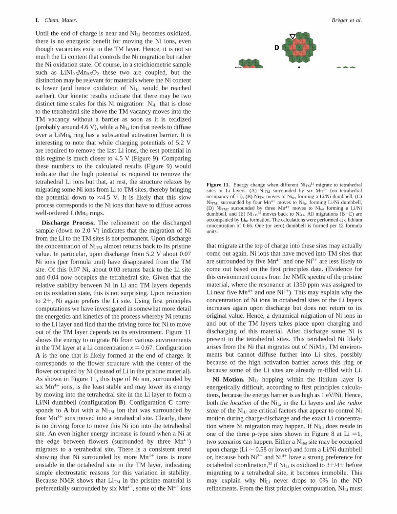
Discharge Process.The refinement on the dischargedsample (down to 2.0 V) indicates that the migration of Nifrom the Li to the TM sites is not permanent. Upon dischargethe concentration of NiTM almost returns back to its pristinevalue. In particular, upon discharge from 5.2 V about 0.07Ni ions (per formula unit) have disappeared from the TMsite. Of this 0.07 Ni, about 0.03 returns back to the Li siteand 0.04 now occupies the tetrahedral site. Given that therelative stability between Ni in Li and TM layers dependson its oxidation state, this is not surprising. Upon reductionto 2+, Ni again prefers the Li site. Using first principlescomputations we have investigated in somewhat more detailthe energetics and kinetics of the process whereby Ni returnsto the Li layer and find that the driving force for Ni to moveout of the TM layer depends on its environment. Figure 11shows the energy to migrate Ni from various environmentsin the TM layer at a Li concentrationx ) 0.67. ConfigurationA is the one that is likely formed at the end of charge. Itcorresponds to the flower structure with the center of theflower occupied by Ni (instead of Li in the pristine material).As shown in Figure 11, this type of Ni ion, surrounded bysix Mn4+ ions, is the least stable and may lower its energyby moving into the tetrahedral site in the Li layer to form aLi/Ni dumbbell (configurationB). ConfigurationC corre-sponds toA but with a NiTM ion that was surrounded byfour Mn4+ ions moved into a tetrahedral site. Clearly, thereis no driving force to move this Ni ion into the tetrahedralsite. An even higher energy increase is found when a Ni atthe edge between flowers (surrounded by three Mn4+)migrates to a tetrahedral site. There is a consistent trendshowing that Ni surrounded by more Mn4+ ions is moreunstable in the octahedral site in the TM layer, indicatingsimple electrostatic reasons for this variation in stability.Because NMR shows that LiTM in the pristine material ispreferentially surrounded by six Mn4+, some of the Ni4+ ions
that migrate at the top of charge into these sites may actuallycome out again. Ni ions that have moved into TM sites thatare surrounded by five Mn4+ and one Ni2+ are less likely tocome out based on the first principles data. (Evidence forthis environment comes from the NMR spectra of the pristinematerial, where the resonance at 1350 ppm was assigned toLi near five Mn4+ and one Ni2+). This may explain why theconcentration of Ni ions in octahedral sites of the Li layersincreases again upon discharge but does not return to itsoriginal value. Hence, a dynamical migration of Ni ions inand out of the TM layers takes place upon charging anddischarging of this material. After discharge some Ni ispresent in the tetrahedral sites. This tetrahedral Ni likelyarises from the Ni that migrates out of NiMn6 TM environ-ments but cannot diffuse further into Li sites, possiblybecause of the high activation barrier across this ring orbecause some of the Li sites are already re-filled with Li.
Ni Motion. NiLi hopping within the lithium layer isenergetically difficult, according to first principles calcula-tions, because the energy barrier is as high as 1 eV/Ni. Hence,both the locationof the NiLi in the Li layers andthe redoxstateof the NiLi are critical factors that appear to control Nimotion during charge/discharge and the exact Li concentra-tion where Ni migration may happen. If NiLi does reside inone of the three p-type sites shown in Figure 8 at Li)1,two scenarios can happen. Either a Nitet site may be occupiedupon charge (Li∼ 0.58 or lower) and form a Li/Ni dumbbellor, because both Ni3+ and Ni4+ have a strong preference foroctahedral coordination,32 if Ni Li is oxidized to 3+/4+ beforemigrating to a tetrahedral site, it becomes immobile. Thismay explain why NiLi never drops to 0% in the NDrefinements. From the first principles computation, NiLi must
Figure 11. Energy change when different NiTMLi migrate to tetrahedral
sites or Li layers. (A) NiTM surrounded by six Mn4+ (no tetrahedraloccupancy of Li), (B) NiTM moves to Nitet forming a Li/Ni dumbbell, (C)NiTM1 surrounded by four Mn4+ moves to Nitet forming Li/Ni dumbbell,(D) NiTM2 surrounded by three Mn4+ moves to Nitet forming a Li/Nidumbbell, and (E) NiTM
Li moves back to NiLi. All migrations (B-E) areaccompanied by Litet formation. The calculations were performed at a lithiumconcentration of 0.66. One (or zero) dumbbell is formed per 12 formulaunits.
L Chem. Mater. Breger et al.
be 4+ to be energetically favorable to move to the TM layer.Therefore, NiTM
Li migration is only expected at very highpotential (low Li concentration 0.33 to 0).
Importance of the State of Order in the Material onthe Structural Evolution. The computational results showthat a well-ordered flower structure is least likely to reduceits Li/Ni exchange with cycling, for a number of reasons.The most stable site for Ni in the Li layer is away from thevacant LiTM
V site that it needs to occupy. Diffusion of thisNi requires a hop through a tetrahedral site that face-shareswith a Mn4+ octahedron. Such a hop has a very highactivation barrier.15 But most importantly, the site that Nican occupy in the TM layer is surrounded by six Mn4+ ions,which we find to be the least stable at the NiTM
Li site. Hence,even if this Ni migrates to the TM layer, it is also most likelyto come back out upon discharge. In less ordered materials,not all LiTM is surrounded by six Mn4+ ions, and LiMn5Niand LiMn4Ni2 exist,18 as seen by NMR and in our simulationsof the partially disordered state (Figure 1d). Such a lack ofperfect LiMn6 rings will give NiLi better access to the vacancyin the TM layer and lead to a more stable site once the Nihas migrated there. This may be one reason why in generalquenched samples of LiNi0.5Mn0.5O2 (less well-ordered) showbetter electrochemical properties than samples that are slowlycooled or annealed.40
Conclusions
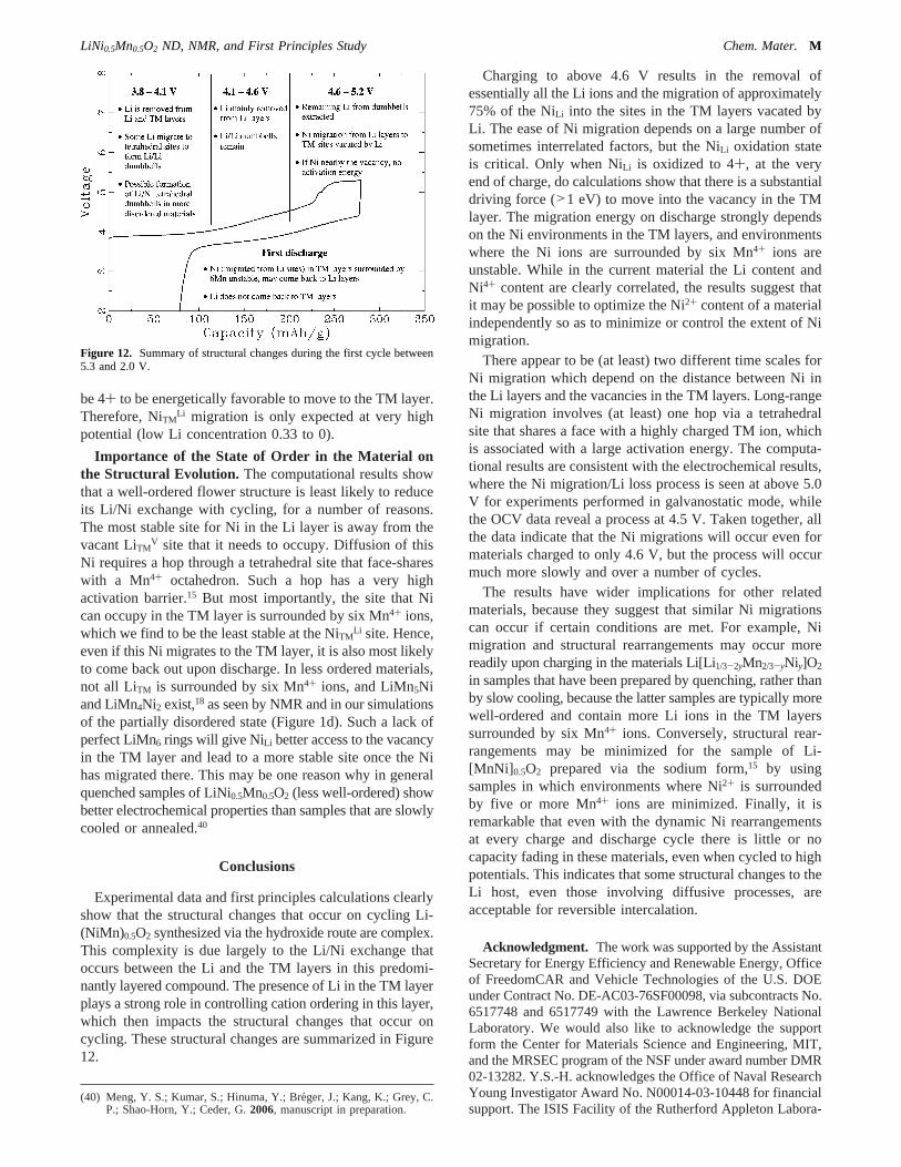
Experimental data and first principles calculations clearlyshow that the structural changes that occur on cycling Li-(NiMn)0.5O2 synthesized via the hydroxide route are complex.This complexity is due largely to the Li/Ni exchange thatoccurs between the Li and the TM layers in this predomi-nantly layered compound. The presence of Li in the TM layerplays a strong role in controlling cation ordering in this layer,which then impacts the structural changes that occur oncycling. These structural changes are summarized in Figure12.
Charging to above 4.6 V results in the removal ofessentially all the Li ions and the migration of approximately75% of the NiLi into the sites in the TM layers vacated byLi. The ease of Ni migration depends on a large number ofsometimes interrelated factors, but the NiLi oxidation stateis critical. Only when NiLi is oxidized to 4+, at the veryend of charge, do calculations show that there is a substantialdriving force (>1 eV) to move into the vacancy in the TMlayer. The migration energy on discharge strongly dependson the Ni environments in the TM layers, and environmentswhere the Ni ions are surrounded by six Mn4+ ions areunstable. While in the current material the Li content andNi4+ content are clearly correlated, the results suggest thatit may be possible to optimize the Ni2+ content of a materialindependently so as to minimize or control the extent of Nimigration.
There appear to be (at least) two different time scales forNi migration which depend on the distance between Ni inthe Li layers and the vacancies in the TM layers. Long-rangeNi migration involves (at least) one hop via a tetrahedralsite that shares a face with a highly charged TM ion, whichis associated with a large activation energy. The computa-tional results are consistent with the electrochemical results,where the Ni migration/Li loss process is seen at above 5.0V for experiments performed in galvanostatic mode, whilethe OCV data reveal a process at 4.5 V. Taken together, allthe data indicate that the Ni migrations will occur even formaterials charged to only 4.6 V, but the process will occurmuch more slowly and over a number of cycles.
The results have wider implications for other relatedmaterials, because they suggest that similar Ni migrationscan occur if certain conditions are met. For example, Nimigration and structural rearrangements may occur morereadily upon charging in the materials Li[Li1/3-2yMn2/3-yNiy]O2
in samples that have been prepared by quenching, rather thanby slow cooling, because the latter samples are typically morewell-ordered and contain more Li ions in the TM layerssurrounded by six Mn4+ ions. Conversely, structural rear-rangements may be minimized for the sample of Li-[MnNi] 0.5O2 prepared via the sodium form,15 by usingsamples in which environments where Ni2+ is surroundedby five or more Mn4+ ions are minimized. Finally, it isremarkable that even with the dynamic Ni rearrangementsat every charge and discharge cycle there is little or nocapacity fading in these materials, even when cycled to highpotentials. This indicates that some structural changes to theLi host, even those involving diffusive processes, areacceptable for reversible intercalation.
Acknowledgment. The work was supported by the AssistantSecretary for Energy Efficiency and Renewable Energy, Officeof FreedomCAR and Vehicle Technologies of the U.S. DOEunder Contract No. DE-AC03-76SF00098, via subcontracts No.6517748 and 6517749 with the Lawrence Berkeley NationalLaboratory. We would also like to acknowledge the supportform the Center for Materials Science and Engineering, MIT,and the MRSEC program of the NSF under award number DMR02-13282. Y.S.-H. acknowledges the Office of Naval ResearchYoung Investigator Award No. N00014-03-10448 for financialsupport. The ISIS Facility of the Rutherford Appleton Labora-
(40) Meng, Y. S.; Kumar, S.; Hinuma, Y.; Bre´ger, J.; Kang, K.; Grey, C.P.; Shao-Horn, Y.; Ceder, G.2006, manuscript in preparation.
Figure 12. Summary of structural changes during the first cycle between5.3 and 2.0 V.
LiNi0.5Mn0.5O2 ND, NMR, and First Principles Study Chem. Mater.M

tory is thanked for access to GEM. This work has benefitedfrom the use of NPDF at the Lujan Center at the Los AlamosNeutron Science Center, funded by the DOE Office of BasicEnergy Sciences (BES), Los Alamos National Laboratory, andthe DOE under Contract No. W-7405-ENG-36. The upgradeof NPDF has been funded by NSF through Grant DMR 00-76488. This work has benefited from the use of the IntensePulsed Neutron Source at Argonne National Laboratory. Thisfacility is funded by the U.S. DOE under Contract No. W-31-109-ENG-38. Use of the NSLS, Brookhaven National Labora-tory, was supported by the U.S. DOE, Office of BES, underContract No. DE-AC02-98CH10886. We are grateful for theassistance given to us at the different beam lines from ThomasProffen (NPDF, LANL), Winfried Kockelmann (GEM, ISIS),Yongjae Lee (X7A, NSLS), James Richardson, Evan Maxey,
and Ashfia Huq (GPPD, IPNS). We thank Jordi Cabana forelectrochemical measurements as well as Matthias Gutmann andAlan Soper for their help in neutron data analysis.
Supporting Information Available: Voltage vs specific capac-ity curves for LiNi0.5Mn0.5O2 used for ND and in situ XRDexperiments, and LiNi0.5Mn0.5O2, table showing the sensitivity ofthe refinement to the Li occupancy of the tetraheral site for the4.8-2.0 V sample,6Li MAS NMR spectrum of6Li xNi0.5Mn0.5O2
cycled between 4.8 and 2.0 V, calculation of the capacity associatedwith PF6
- intercalation in graphite, ND data, and evolution of thea parameter using the in situ XRD patterns of LiNi0.5Mn0.5O2 (PDF).This material is available via the Internet at http://pubs.acs.org.
CM060886R
N Chem. Mater. PAGE EST: 13.2 Breger et al.