Embed Size (px)
Citation preview

Imagem
Khawaja Khalid Raza
Effect of grooved surface texturing on the behavior of lubricated
contacts
Submitted in partial fulfillment of the requirements for the degree of Masters in Tribology of Surface and Interfaces
2016

Influência da texturização superficial no comportamento de
contactos lubrificados
Effect of grooved surface texturing on the behavior of lubricated
contacts
Submitted in Partial Fulfilment of the Requirements for the Joint European Master in tribology of
Surfaces and Interfaces
Author: Khawaja Khalid Raza
Supervisors:
Amílcar Ramalho, Associated Professor at University of Coimbra
Luis Vilhena, Researcher at University of Coimbra
Jury:
Bruno Trindade, Associated Professor at University of Coimbra
Stephen Muhl, Researcher at University of Mexico
Paulo Ferreira, Full Professor at University of Austin (USA)
Coimbra, July, 2016

ii
Acknowledgement
First, I am heartily thankful to my Supervisors Professor Amílcar Ramalho and Dr. Luis Vilhena
whose encouragement, guidance and support from the initial to the final level enabled me to
develop an understanding of this work. This work couldn’t be completed without the effort and
co-operation of Dr. Luis Vilhena. His contributions are sincerely appreciated and gratefully
acknowledged. I would also like to take this opportunity to thank my teacher, Professor Albano
Cavaleiro for his guidance. Many thanks for TRIBOS Consortium who selected me in this
prestigious program. I pay my special thanks to all Professors, lecturers and Colleagues whose
knowledge and support help me completion of this master’s program. I would like to thank my
teacher Mr. Bilal Saleem who introduced me about tribology. Above all, to the great Almighty
God, who is author of all knowledge’s and wisdoms.

iii
LIST OF FIGURES
Figure 2.1. Segments of piston rings……………………………………………………… …....8
Figure 2.2. A view of pores on the SiC ring (magnification x25)………………………………10
Figure 3.1. The hydrodynamic effect of the single idealized dimple…………………………..11
Figure 3.2. (a) Schematic of a computational cell with a moving smooth wall against a stationary
textured wall with inlet textures, showing key geometry. (b) Prediction for pressure on top
wall………………………………………………………………………………………………12
Figure3.3.The Spatial Texture Density (D/L) for 2D Textured Model………………………….13
Figure3.4. The Coefficient of Friction vs. the Spatial Texture Density (D /L)………………….14
Figure 3.5. Stribeck curves showing modes of lubrication………………………………..……..17
Figure3.6. The Stribeck curves of the ground, polished and dimpled (textured)………………..18
Figure3.7. Effect of shape and orientation of texture on friction………………………………...22
Figure 3.8. Summary of the performance of the textured surfaces in starved boundary lubricated
sliding…………………………………………………………………………………………….23
Figure3.9.Effect of viscosity on Stribeck Curve…………………………………………………24
Figure 4.1. Pattern geometry and dimensions……………………………………………… …..28
Figure 4.2. Micrographs of surface textured patterns: (a) textured with low density-TLowD
textured with medium density-TMediumD and, (c) textured with high density-THighD……….29
Figure 4.3. 2D profile of TLowD specimen illustrating the shape and dimensions of typical
micro-grooves……………………………………………………………………………………30
Figure 4.4. Roughness profile (single cone)…………………………………………………..…30
Figure 4.5. Block on ring sliding test tribometer used for testing………………………… ……31
Figure 4.6. Schematic diagram of the block-on-ring sliding test tribometer…………… ……...33
Figure 5.1. Variation in coefficient of friction with sliding speed for un-textured and textured
surfaces lubricated with ISO VG 40: 40 = 46.8 mm2/s and at 40 N applied load...……………35
Figure 5.2. Variation in coefficient of friction with sliding speed for un-textured and textured
surfaces lubricated with ISO VG 320: 40 = 320 mm2/s (FN = 40 N)………………………….36
Figure 5.3. Variation in coefficient of friction with sliding speed for un-textured and textured
surfaces lubricated with ISO VG 150: 40 = 150 mm2/s (FN = 40 N)………………………….37

iv
Figure 5.4. Variation in coefficient of friction with sliding speed for un-textured and textured
surfaces lubricated with ISO VG 40: 40 = 46.8 mm2/s and ISO VG 320: 40 = 320 mm2/s
(FN = 40 N)……………………………………………………………………………………...38 Figure 5.5. Variation in coefficient of friction with sliding speed for un-textured and textured
surfaces lubricated with ISO VG 40: 40 = 46.8 mm2/s and ISO VG 150: 40 = 150 mm2/s (FN =
40 N)…………………………………………………………………………………………….40
Figure 5.6. Variation in coefficient of friction with sliding speed for un-textured surfaces
lubricated with ISO VG 40: 40 = 46.8 mm2/s (PAO8), ISO VG 150: 40 = 150 mm2/s and ISO
VG 320: 40 = 320 mm2/s (FN = 40 N)………………………….………………………………41
Figure 5.7. Variation in coefficient of friction for textured and un-textured surfaces lubricated
with ISO VG 40: 40 = 46.8 mm2/s (PAO8), ISO VG 150: 40 = 150 mm2/s and ISO VG 320:
40 = 320 mm2/s (FN = 40 N)……………………………………….……...…………………...42
Figure 5.8. Average Stribeck curves for textured and un-textured surfaces lubricated with ISO
VG 40: 40 = 46.8 mm2/s (PAO8), ISO VG 150: 40 = 150 mm2/s and ISO VG 320: 40 = 320
mm2/s (FN = 40 N)………………………………………....…………………………………….43
v
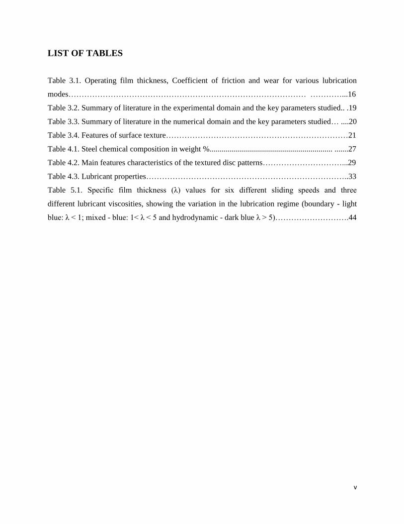
LIST OF TABLES
Table 3.1. Operating film thickness, Coefficient of friction and wear for various lubrication
modes……………………………………………………………………………… …………...16
Table 3.2. Summary of literature in the experimental domain and the key parameters studied.. .19
Table 3.3. Summary of literature in the numerical domain and the key parameters studied… ....20
Table 3.4. Features of surface texture……………………………………………………………21
Table 4.1. Steel chemical composition in weight %.............................................................. .......27
Table 4.2. Main features characteristics of the textured disc patterns…………………………...29
Table 4.3. Lubricant properties…………………………………………………………………..33
Table 5.1. Specific film thickness (λ) values for six different sliding speeds and three
different lubricant viscosities, showing the variation in the lubrication regime (boundary - light
blue: λ < 1; mixed - blue: 1< λ < 5 and hydrodynamic - dark blue λ > 5)……………………….44

vi
SYMBOLOGY AND ACRONYMS
Symbology:
Ap: pattern area density.
B: rhomb width.
t: the groove width.
α: the intersection angle.
Acronyms:
HD: Hydrodynamic lubrication.
EHL: Elasto-hydrodynamic lubrication.
BL: Boundary lubrication.
DLC: Diamond like carbon.
LST: Laser surface texturing.
RIE: Reactive ion etching.
PL: Photolithography.
KOH: Potassium hydroxide.
DRIE: Deep reactive ion etching.
PAG: Polyalkylene glycol.
POE: Polyol ester.
VG: Viscosity grade.
NS: Navier-Stokes.
FT: Film thickness.
Re: Reynolds number.
C/S: cross-section
Soft elasto-hydrodynamic lubrication (SEHL)

vii
Abstract
The goal of this research study was to investigate the effect of grooved surface texturing with
a rhombic geometry under different lubrication regimes. Tribological study under
unidirectional sliding was focused on the effect of texturing parameters such as groove depth,
groove width, distance between grooves and pattern area density on the coefficient of friction
under different lubrication regimes achieved by varying sliding speed and lubricant viscosity.
Three types of grooved patterns with different textured area densities were produced on steel
samples by electrical discharge machining (EDM). The largest gain in terms of friction
reduction was observed by using lowest texture density specimen by using medium viscosity
oil (ISOVG 150) at higher sliding speeds. Inspection of sliding surfaces has not revealed any
measurable wear for the contact conditions investigated.
Keywords: Surface texturing, grooves, block-on-ring, Stribeck curves

viii
Resumo
O objetivo deste estudo foi investigar o efeito de texturização de superfície sulcada com uma
geometria rômbica sob diferentes regimes de lubrificação. O estudo tribológico sob deslizamento
unidirecional foi focado no efeito dos parâmetros de texturização, como a profundidade do canal,
largura do canal, distância entre sulcos e densidade de área de padrão sobre o coeficiente de
atrito sob diferentes regimes de lubrificação conseguido através da variação da velocidade de
deslizamento e viscosidade do lubrificante. Três tipos de padrões sulcados com diferentes
densidades de área texturizados foram produzidos em amostras de aço por eletroerosão (EDM).
Os resultados desta investigação mostraram que, sob a lubrificação fronteira, as texturas resistem
ao deslizamento, assim, resultando em maior atrito. O maior ganho em termos de redução de
atrito foi observada sob lubrificação hidrodinâmica. Inspeção das superfícies deslizantes não
revelou nenhum desgaste mensurável para as condições de contacto investigados.
Palavras-chave: texturização de superfície, sulcos, calços, no anel, curvas Stribeck

ix
Table of contents
1. Introduction ............................................................................................................................................. 1
1.1. Objectives.......................................................................................................................................... 1
1.2. Importance of texturing .................................................................................................................. 1
1.3. Parameters in surface texturing ..................................................................................................... 2
1.4. Methods of texturization ................................................................................................................. 4
1.5. Thesis structure ................................................................................................................................ 4
1.5.1. Previous experimental approach ............................................................................................. 4
1.5.2. New experimental approach .................................................................................................... 5
1.5.3. Contact geometry ...................................................................................................................... 5
1.5.4. Unidirectional test ..................................................................................................................... 5
1.5.5. Stribeck curves .......................................................................................................................... 6
2. Industrial problems and scope of texturization.................................................................................... 7
2.1. Reciprocating automotive components .......................................................................................... 7
2.2. Automobile engine mechanical components .................................................................................. 8
2.2.1. Piston-cylinder system .............................................................................................................. 8
2.2.2. Piston rings ................................................................................................................................ 8
2.2.3. Seals, pumps and valves............................................................................................................ 9
2.2.4. Cylinder liner ............................................................................................................................ 9
2.2.5. Mechanical Seals ..................................................................................................................... 10
2.2.6. Journal and thrust bearings ................................................................................................... 10
3. State of art ............................................................................................................................................. 11
3.1. Basic theory of texturization ......................................................................................................... 11
3.2. Use of dimples for textured surfaces ............................................................................................ 12
3.3. Spatial texture density ................................................................................................................... 13
3.4. Effect of texturing on Stribeck curves .......................................................................................... 15
3.4.1. Effects of texture size, shape, area fraction, and orientation .............................................. 21
3.4.2. Effect of sliding velocity and lubricant viscosity on film thickness .................................... 24
4. Materials and Methods ......................................................................................................................... 26
4.1. Types of Pattern ............................................................................................................................. 27

x
4.1.1. Specimens ................................................................................................................................. 27
4.2. Characterization of samples surface ............................................................................................ 30
4.3. Calculation of cone area ................................................................................................................ 31
4.4. Experimental procedure ................................................................................................................ 31
5. Results and discussion .......................................................................................................................... 34
5.1. Effect of lubricant viscosity and pattern area density on COF.................................................. 34
5.1.1. ISO VG 46 (PAO8) .................................................................................................................. 34
5.1.2. High viscosity oil – ISO VG 320 ............................................................................................. 35
5.1.3. Medium viscosity oil – ISO VG 150 ....................................................................................... 36
5.2. Comparison between different lubricant viscosities ................................................................... 37
5.2.1. Comparison between low viscosity (ISO VG 46) and high viscosity (ISO VG 320) oil ..... 37
5.2.2. Comparison between low viscosity (ISO VG 46) and medium viscosity (ISO VG 150) oil
............................................................................................................................................................ 39
5.3. Stribeck curves ............................................................................................................................... 40
5.4. Effect of sliding velocity and lubricant viscosity on transitions in lubrication regimes .......... 43
6. Conclusions ............................................................................................................................................ 45
Biblography ............................................................................................................................................... 46

1
1. Introduction
1.1. Objectives
The main purpose of this work was to decrease coefficient of friction and improving wear
performance by means of patterning of steel surface. So, the objective was to first investigate
effect of incorporating texturing such as grooves on frictional behavior of steel specimen’s
surface under lubricated conditions. Grooved patterns with different densities were prepared. The
goal was to get Stribeck curves by selecting proper experimental conditions like load, speed and
viscosity conditions. The literature shows that by using texturing effect surfaces can increase
their capacity for higher loads. The reason is that dimples or groove provides reservoir for oil
and collecting wear particles from surfaces.
1.2. Importance of texturing
Characteristics of contact surfaces has great influence on tribological behaviour of the contact,
including friction and wear, and thus determining energy consumption and system efficiency.
Ever increasing demands for capacity and reliability of mechanical systems and especially
smaller consumptions of energy, fuels and lubricants, dictate use of new advanced materials and
surface technologies, which would increase efficiency and reduce energy consumption and
impact on environment. Right tribological characteristics of contact surfaces, being greatly
influenced by surface topography, determine the possibility for energy saving and mechanical
systems efficiency improvement [1,2].
From a standpoint of reducing energy consumption and increasing systems efficiency, one of the
most important surface characteristics is its roughness or topography and its impact on friction
and wear. In the field of surface topography and its effect on tribological properties of contact
surfaces, a lot of research work has already been done [3-10], which in the case of surface
texturing usually doesn't have physical background and doesn’t give correlations between
texturing parameters and friction. However, research work in the area of surface texturing, the
way to modify contact surface through formation of micro-dimples or micro-channels shows that
by using suitable structure of micro-dimples and grooves considerable improvement in friction
and wear properties of contact surfaces can be expected [2,11-12].
2
One of the first commercial applications of surface texturing involves honing of cylinder liners in
internal combustion engines. One of the leading carmakers succeeded in reducing fuel
consumption for 2.5 % by the use of micro-dimples on contact surfaces of engine components
[13].
Besides that, surface texturing can be found in the field of magnetic media for storing data,
MEMS (micro-electronic mechanical systems) devices, as well as face seals, piston rings, sliding
bearings etc. The biggest research, however, was done in the field of sliding bearings and face
seals, where laser surface texturing is normally used. [14-15]. In case of hydrodynamic, elasto-
hydrodynamic or mixed lubrication, micro-dimples act as micro-hydrodynamic bearings, and in
conditions of boundary lubrication as micro-reservoir for lubricant and in conditions of dry
sliding as micro-traps for wear particles [16].
Generally, textures fulfill the three major roles depending upon lubrication regime. Firstly, it
traps wear debris. Secondly, it acts as lubricant reservoir and finally, it acts as hydrodynamic
bearing. The wear debris entrapment is one of major effects in any lubrication regime and in any
type of contact. This reduces wear, increases component life and improves fretting fatigue
resistance. Textures act like micro reservoirs for boundary and mixed lubrication regimes and
provides lubricant during whole operating period [17].
1.3. Parameters in surface texturing
The main parameters in texturing are diameter, depth, shape and density of the structure. Effect
of texturing largely depends on operating contact conditions such as sliding speed and contact
pressure. Selection of optimal texturing parameters is still based on experimental approach. This
is also the main reason for very large variation of texturing parameters, which different authors
are describing as optimal. Solutions, which are already in use in practice, are mainly the result of
extensive experimental testing and hunting for optimal solution for a given application.
Incorporation of solid lubricants on to textured and coated surface too decreases friction
coefficient and increases wear resistance [18].
Friction reduction in parts of combustion engines improves efficiency and reduces fuel
consumption. Therefore, the various options like improved design of contact surfaces,
lubrications, coatings and surface texturing must be used for this purpose. Some texturing

3
features are discontinuous like dimples and pores while others are continuous like grooves and
cross hatched patterns [19].
Various texturing shapes include dimples, grooves, squares, chevrons, ellipses, pyramids.
Surface texturing has emerged in surface engineering which significantly improves load
capacity, wear resistance and friction coefficient. The load carrying capacity of textured journal
bearing increases at constant speed and oil supply with respect to smooth journal bearing.
Similarly, the same is the case with increase of maximum pressure while keeping load and oil
pressure constant [20].
Texturing changes flow and film thickness of lubricating film across contact region. It also
serves as channels to supply lubricant to the surface and alters bearing pressure distribution [21].
Friction relates to asperity shape and slope, asperity shape and slope relates to surface texture.
Conventional electrical discharge machining (EDM) can be used for macro- and micro-surface
patterning. Conventional electrical discharge machining is based on the evaporation of material
by electrical arcs between electrode and machined surface [22]. This work focuses on textured
discs produced by electric discharge machining. The proper selection of texture shapes, sizes,
spacing’s, and orientation is important to enhance the performance of lubricated contacts [23].
LST produces a very large number of micro-dimples on the surface and each of these micro
dimples can serve either as a micro-hydrodynamic bearing in cases of full or mixed lubrication, a
micro-reservoir for lubricant in cases of starved lubrication conditions, or a micro-trap for wear
debris in either lubricated or dry sliding [24]. Study shows that surface texturing can reduce
friction only if the dimple diameters are smaller than the contact width [12,25], while others
show that friction increases under these conditions [26].
In an experiment pin on disc machine was used for measuring friction coefficients to see effect
of LST by microdimpling on lubrication regime transitions during unidirectional sliding. LST
expanded the range of the hydrodynamic lubrication regime for both high- and low viscosity oil
lubricants in terms of load and sliding speed. After laser texturing, removal of the bulges at the
edge of dimples by lapping is essential to optmize the beneficial effect of LST on lubrication
regime transitions. Also, LST reduced the friction coefficient under similar operating conditions,
when compared with untextured surfaces. It has been observed that a lower area dimple density
is more beneficial for lubrication regime transitions. Hence, LST can be used to reduce friction
in lubricated contacts that are operating under a boundary lubrication regime [27].

4
1.4. Methods of texturization
The simplest way to texture a surface for low friction is to make it rougher and then remove the
protruding edges. Similarly, other techniques are laser and electron beam texturing. Now a days
honing of cylinder surface and piston rings is done in combustion engines by cross hatching
using some hard abrasives for better tribological properties. The texturing methods are abrasive
jet machining (AJM), laser beam machining (LBM), lithography, deep x-ray lithography
(DXRL), also known as (LIGA) and anisotropic etching. However, the most widely used
technologies are laser surface texturing (LST) and reactive ion-beam etching (RIE). These
methods are used to create micro dimples of different shapes, dimensions, depth, and distance
between dimples on variety of material surfaces. LST is the most cost effective method, but a
disadvantage of LST is the creation of bulges around dimples during the laser impulse impact
and thermal cracks formation, especially on ceramics materials. Nevertheless, as numerous
researches noted, the bulges could be easily removed by light polishing or at running-in period.
RIE, AJM, LBM, lithography, LIGA technologies permit to produce dimples without material
damages during texturing but these methods are more expensive [28].
1.5. Thesis structure
This thesis will cover the study that was done in the last year by Dmitrii Sergachev. He studied a
lubricated contact of texturized flat surfaces against spherical ball using reciprocating tests with
2.5 mm stroke, ball of 10 mm in diameter and loads from 20 to 50N. The results obtained were
not conclusive about the improvement that can be obtained by texturing.
1.5.1. Previous experimental approach
The coefficient of friction obtained by previous approach was very high for lubricated contacts.
The values were from 0.15 to 0.2 for plain steel and 0.1 to 0.15 for coatings. Coatings
delaminated at edges of textures while performing ball on disc test. It was caused by low contact
areas in regards to groove width which caused lateral forces during ball deformation. It was
reciprocating test, so speed increases from zero to maximum value.

5
Delamination’s induced fluctuations in friction coefficient curves. Patterns with large dimple size
should be tested again large flat surfaces to obtain sufficient results. Use of ball as a counter
surface applies severe limitations on pattern dimensions, which increases texturing costs and not
necessarily show better results in case of parallel surfaces. Textured surface area should be
minimized along with the groove width to decrease abrasive wear and adhesion. Influence of
counter surface velocity, load, sliding direction and lubricant viscosity on the optimal distance
between grooves should be studied.
1.5.2. New experimental approach
The main objective of this research was to study effect of texturing to improve wear resistance
and reduce friction in boundary lubrication regime in some tribological applications. The aim
was to use same materials and texturing as Dmitrii Sergachev used in his study but changing
experimental approach so that to get proper results to draw Stribeck curves. Following
approaches were used in these experiments.
1.5.3. Contact geometry
Block on ring configuration was used instead of pin or ball on disc. It has following advantages.
Contact area is large enough to study tribological effects on larger scales. In this way, normal
load may be assumed as constant parameter to study effect of other parameters such as speed and
viscosity. Furthermore, this contact geometry allows to study effect of texturing on larger contact
area, which is expected to enhance the effect of the channel type available textures.
1.5.4. Unidirectional test
Test was unidirectional instead of reciprocating so as to get constant speed in whole test.

6
1.5.5. Stribeck curves
Samples with different pattern area density were used. Tests were performed with three
lubricants with different viscosities. The Stribeck curve was obtained in one set of tests with
constant normal load of 40 N by changing the rotational speed of disc in several steps. Different
tests performed with un-textured and textured specimens under lubricated condition using three
lubricants with different viscosities. The value of speed decides thickness of film and lubrication
regime. So, it is easy at the end to get different data points for drawing a Stribeck curve.

7
2. Industrial problems and scope of texturization
2.1. Reciprocating automotive components
Energy losses resulting from friction between contact surfaces in an internal combustion engine
have been studied intensively by a considerable number of tribologists. Still, the automotive
industry needs further improvements to reduce friction-related energy losses in engines and drive
systems. This problem can be solved by applying porous surfaces such as surface texturing. This
work mainly focuses on tribological problems in sliding parts of automobiles combustion
engines such as pistons with cylinders and polymer injection molding company.
Surface texturing in reciprocating automotive components also displayed a positive effect. In the
Reynolds equation and the equation of motion are served simultaneously for as simplified
“piston/cylinder” system with surface texturing. The solution provides behavior of both the
clearance and the friction force between the “piston ring” and “cylinder liner” surfaces. It is
shown that optimum surface texturing may substantially reduce the friction losses in
reciprocating automotive components [29]. The experimental study evaluates the effect of partial
laser surface texturing (LST) on friction reduction in piston rings. It was found that the partial
LST piston rings exhibited about 25% lower friction [30-33].
Fuel consumption is an extremely important parameter for the automotive industry today. In
engines the piston system is the largest source of frictional losses, accounting for about 30% of
the total frictional losses, thus it is important to optimize. The lost caused by friction and wear is
huge. There is about 30% power of automobile engine lost because of friction, 19% of the power
loss is come from the piston ring-cylinder liner pair. This important pair of engine often damaged
because of wear. Operational characteristics combined with the rings artificial texturing,
influences the engine reliability and efficiency. Sliding components in automobiles combustion
engine parts such as piston ring with cylinder and other machine parts operates at low sliding
speeds and high load conditions. Therefore, coefficient of friction increases [34].
Proper lubrication and surface texture are key issues in reducing friction in a piston/cylinder
system and, hence, have received great deal of attention in the relevant literature. Surface
texturing as a means for enhancing tribological properties of mechanical components is well
known for many years. Perhaps the most familiar and earliest commercial application of surface
texturing in engines is that of cylinder liner honing. Surface texturing in general and laser surface

8
texturing (LST) in particular has emerged in recent years as a potential new technology to reduce
friction in mechanical components [35].
2.2. Automobile engine mechanical components
2.2.1. Piston-cylinder system
2.2.2. Piston rings
Experimental study is presented to evaluate the effect of partial laser surface texturing (LST) on
friction reduction in piston rings. In a previous study, 30% friction reduction was obtained with
full LST where the full width of the piston ring is textured with a very large number of micro
dimples that act individually as micro hydrodynamic bearings. In partial LST, only a portion of
the piston-ring width is textured with high dimple density producing a “collective” effect of the
dimples that provides an equivalent converging clearance even with nominally parallel mating
surfaces [13]. I.Etsion and Y.Kligerman [2,13] found that a friction reduction of 30% and even
more is feasible with textured surfaces. Figure 2.1 below shows partially and fully textured
segments of piston rings.
Figure 2.1. Segments of piston rings: (a) fully textured; (b) partially textured [13].

9
LST has a substantial effect on friction reduction compared to the non-textured reference rings.
Piston rings were tested with partial surface texturing. Tests were performed on a reciprocating
test rig with actual piston rings and cylinder liner segments. After this, comparison was made
between the performance of a reference non-textured conventional barrel shape rings and
optimum partial LST cylindrical shape rings. A model was developed to judge the potential of
LST in Soft Elasto Hydrodynamic Lubrication. Significant friction reduction of about 20% can
be achieved with optimum LST slider in comparison with a non-textured slider [36].
2.2.3. Seals, pumps and valves
Laser can be used to generate micro pores on T8 steel surface and the structure and morphology
features of surface micro pores were observed. Tribological experiments were conducted with a
ring-on-disc tester under various loads and speeds. It is shown that the maximum PV value of
face seal can be increased by hydrodynamic effect of micro pores. Frictional properties of laser-
micro pored surface were assessed through ring-on-disc tests, simulating a face seal contact
interface with different loads and speeds. The findings are concluded as follows: All the surfaces
had similar trends with the friction coefficients decreased at the initial stage and increased
gradually with load and speed. Compared with the polished surface, the laser-micropored seal
surface can improve the maximum PV value to 2.5 times. LST effectively increases load
capacity and reduces friction in SEHL [18]. Textured surfaces have applications in fluid power
systems such as seals, pumps and valves to significantly reduce friction and wear in these
systems [16].
2.2.4. Cylinder liner
An optimal texturing design method on cylinder liner was proposed. It shows that on cylinder
liner, texturing with variable parameters in different velocity ranges can produce higher load
carrying capacity and film thickness than that with invariable parameters. The same results can
be found at the top and bottom dead center, indicating that it is a good method to improve the
hydrodynamic lubrication effect than others [37].

10
2.2.5. Mechanical Seals
In an experiment qualitative results of simulations showed that hydrodynamic force was
dependent on rotational speed and the clearance height. Where pores were larger in depth and
diameter on surface, the pressure was higher and so the hydrodynamic force. The smaller the
radial distance between pores, the larger the hydrodynamic force was observed while no such
effect was observed in circumferential direction. Figure 2.2 shows pores at SIC ring surface. The
greatest effect of surface texturing was reported in the low-pressure zone [38].
Figure 2.2. A view of pores on the SiC ring (magnification x25) [38].
2.2.6. Journal and thrust bearings
It was substantiated that improvement in tribological characteristics of journal and thrust bearing
by surface texturing due to film thickness increasing. It was noted that the coefficient of friction
can be reduced if a texture of suitable geometry is introduced. In addition, the literature revealed
that in the mixed lubrication regime, the so-called secondary lubrication effect in dimpled area is
the main mechanism responsible for performance improvement [39-43].

11
3. State of art
3.1. Basic theory of texturization
Figure 3.1 shows the creation of additional hydrodynamic force due to different hydrodynamic
pressure distribution over diverging and converging parts of the dimple. The pressure decreases
as the flow approaches the bottom center of the dimple. On the symmetrical side, the pressure
increases. Figure 3.1 shows hydrodynamic effect of single idealized dimple.
Figure 3.1. The hydrodynamic effect of the single idealized dimple [28].
Another effect acts on the condition of mixed lubrication between intimate contacting surfaces.
The liquid trapped in the low region of the texture can be considered as a secondary source of
lubricant, which is drawn by the relative movement to permeate into surrounding areas to reduce
the friction and retard the galling. It is called the secondary lubrication effect [28].
Figure 3.2 below shows the simulation cell highlighting the texture geometry and the boundary
conditions:

12
Figure 3.2. (a) Schematic of a computational cell with a moving smooth wall against a stationary
textured wall with inlet textures, showing key geometry. (b) Prediction for pressure on top wall
[16].
3.2. Use of dimples for textured surfaces
It is found that the tribological characteristics depended greatly on the size and density of the
micro-dimples, whilst the dimple shape did not significantly affect the friction coefficient
regardless of rounded or angular profiles. The results showed a large increase of the tool life
when texturing of the substrate was made [44-45]. The direction of study to use dimples of
textured surfaces as the reservoir for solid lubricant for providing a better working ability at dry
friction is intensively developing. It is possible to achieve a significant reduction in friction
coefficient and an increase in the wear life by choosing the optimal geometrical parameters of
the textured surface with the subsequent treatment. The new mathematical models describing
13
tribological behavior of the textured surfaces are regularly appearing that can establish relation
between structure and tribological parameters.
Studies suggest that texturing could be detrimental to tribological performance in non-conformal
contact configuration. It was observed that relatively deep micro-dents in the lubricated contact
results in fluid film thickness reduction and can cause lubricant film breakdown. For shallower
dent, this effect is reduced, or even reversed for very shallow dents. As the conclusion, results
suggest that surface texturing using microdents of an appropriate depth could help to increase
lubrication films capabilities [46].
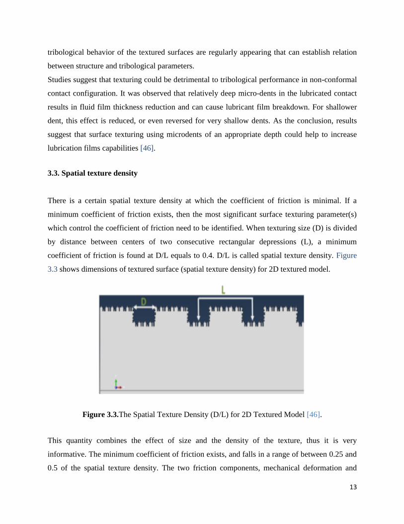
3.3. Spatial texture density
There is a certain spatial texture density at which the coefficient of friction is minimal. If a
minimum coefficient of friction exists, then the most significant surface texturing parameter(s)
which control the coefficient of friction need to be identified. When texturing size (D) is divided
by distance between centers of two consecutive rectangular depressions (L), a minimum
coefficient of friction is found at D/L equals to 0.4. D/L is called spatial texture density. Figure
3.3 shows dimensions of textured surface (spatial texture density) for 2D textured model.
Figure 3.3.The Spatial Texture Density (D/L) for 2D Textured Model [46].
This quantity combines the effect of size and the density of the texture, thus it is very
informative. The minimum coefficient of friction exists, and falls in a range of between 0.25 and
0.5 of the spatial texture density. The two friction components, mechanical deformation and

14
adhesion are inverse to each other when they are plotted vs. spatial texture density. As the spatial
texture density increases, the adhesion decreases but the mechanical deformation increases. The
behavior can be justified due to the change in real contact area which can be measured by the
square of the complement of the spatial texture density (D/L). When the real area of contact
decreases, the adhesion forces decrease. On the other hand, the mechanical deformation
increases due to high stress concentration which result in the flow of material at the interface.
The adhesion force decreases with increase of spatial surface texturing due to the reduction of
the real area of contact. Figure 3.4 shows curve between spatial texture density and COF [46].
Figure 3.4.The Coefficient of Friction vs. the Spatial Texture Density (D /L) [46].
Hard coating is more beneficial in dry sliding conditions while surface texturing works better
with lubricated sliding. It therefore seems reasonable to combine these two to obtain low friction
and wear during sliding, the hydrodynamic force was greatly dependent on the rotational speed.

15
3.4. Effect of texturing on Stribeck curves
Load carrying capacity increases by incorporating texturing on the surface and Stribeck curves
shifts towards left. The aim of this project was to design texturing on the surface and using
various viscosity lubricants to lower the coefficient of friction and wear. Hence the purpose was
to shift Stribeck curve to lower fictional values. Proper selection of pattern type and its
dimensions can reduce coefficient of friction and wear rate. Combined effects of coating and
texturing can give optimum properties for tribological surfaces.
Research work in the area of surface texturing, the way to modify contact surface through
formation of suitable micro-dimples or micro-channels shows that improvement in friction and
wear properties of contact surfaces can be expected. Different types of lubrication regimes exists
depending on the operating conditions. The lubrication regimes are usually divided into three
groups: boundary lubrication, mixed lubrication and hydrodynamic lubrication.
Boundary lubrication Surfaces are in contact, the load is carried by the surface
asperities.
Mixed lubrication The load is carried by both the lubricant film and the asperities in
contact.
Hydrodynamic lubrication The surfaces are not in contact and a full film of lubricant,
usually thicker than 1 µm, is carrying the load.
Elastohydrodynamic lubrication It is a portion of hydrodynamic lubrication where
some elastic surface deformation is possible.
In general, smoother surfaces are better for fluid film lubrication. Indeed, the effects of the film
thickness and surface roughness on lubrication are combined in the so called ratio parameter
defined as the ratio of the film thickness to the composite surface roughness. Eq. 1 shows
specific film thickness is ratio between mean film thickness and composite surface roughness.
Specific film thickness = ʎ = 𝐌𝐞𝐚𝐧 𝐟𝐢𝐥𝐦 𝐭𝐡𝐢𝐜𝐧𝐞𝐬𝐬
𝐂𝐨𝐦𝐩𝐨𝐬𝐢𝐭𝐞 𝐬𝐮𝐫𝐟𝐚𝐜𝐞 𝐫𝐨𝐮𝐠𝐡𝐧𝐞𝐬𝐬 (1)
16
As long as the ʎ ratio is greater than unity, the film thickness exceeds the mean surface
roughness and severe wear is minimized. When ʎ is less than one, the film thickness is smaller
than the asperity height and the most severe wear regime exists (boundary lubrication). When ʎ
becomes greater than four, even the highest asperities will no longer contact and ideal full film or
hydrodynamic lubrication exists. In between these two extremes, ʎ is greater than one and less
than four, is the mixed lubrication regime.
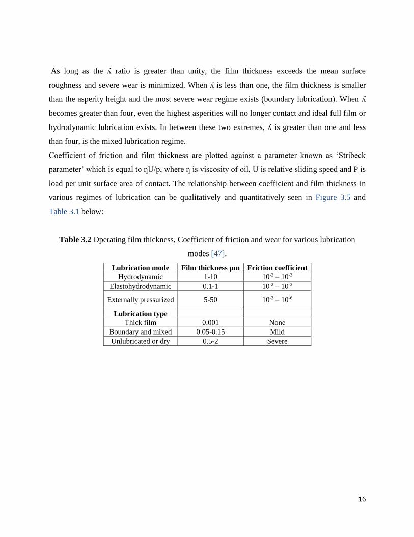
Coefficient of friction and film thickness are plotted against a parameter known as ‘Stribeck
parameter’ which is equal to ƞU/p, where ƞ is viscosity of oil, U is relative sliding speed and P is
load per unit surface area of contact. The relationship between coefficient and film thickness in
various regimes of lubrication can be qualitatively and quantitatively seen in Figure 3.5 and
Table 3.1 below:
Table 3.2 Operating film thickness, Coefficient of friction and wear for various lubrication
modes [47].
Lubrication mode Film thickness µm Friction coefficient
Hydrodynamic 1-10 10-2 – 10-3
Elastohydrodynamic 0.1-1 10-2 – 10-3
Externally pressurized 5-50 10-3 – 10-6
Lubrication type
Thick film 0.001 None
Boundary and mixed 0.05-0.15 Mild
Unlubricated or dry 0.5-2 Severe

17
Figure 3.5.Stribeck curves showing modes of lubrication [47].
The test results showed that laser texturing expanded the contact parameters in terms of load and
speed for hydrodynamic lubrication, as indicated by friction transitions on the Stribeck curve.
The beneficial effects of laser surface texturing are more pronounced at higher speeds and loads,
and with higher viscosity oil [27,48]. Figure 3.6 shows Stribeck curves of ground, polished and
textured (dimple) surfaces.

18
Figure 3.6. The Stribeck curves of the ground, polished and dimpled (textured) [27].
The Table 3.2 below lists the textures tested, the operating conditions and the manufacturing
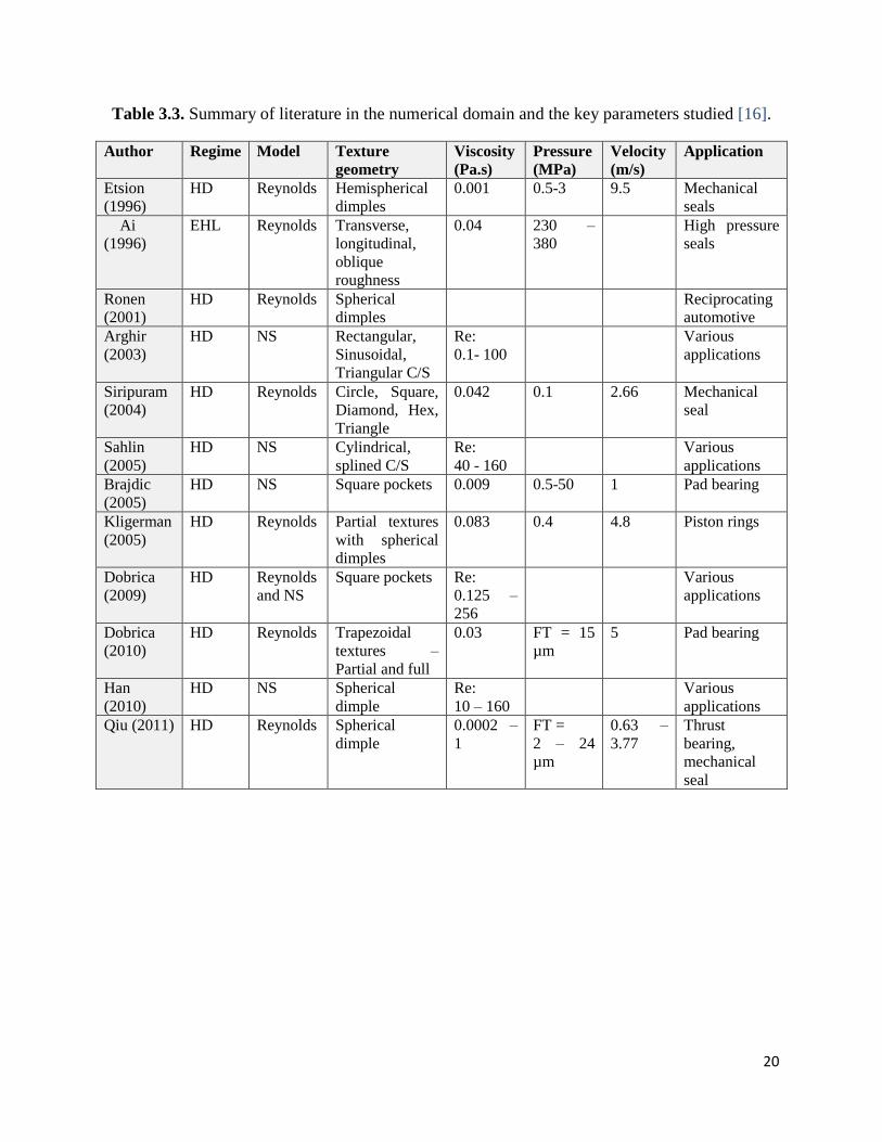
methodology used to produce these microscale textures. Table 3.3 shows the key literature in
numerical study of micro textured surfaces. Key parameters like texture geometry, operating
conditions and the numerical model are listed. Conclusions drawn in terms of the optimum
texture parameters for these conditions are also listed in the table. Micro textured surfaces can
find application in seals, pumps and valves to significantly reduce friction and wear in these
systems.

19
Table 3.2. Summary of literature in the experimental domain and the key parameters studied
[16].
Author Regim
e
Textu
re
width
(µm)
Textu
re
depth
(µm)
Lubrica
nt
Viscosi
ty
@20C
(Pa.s)
Pressu
re
MPa
Velocit
y
m/s
Texture
d
materia
l
Texture
d
method
Geiger
(1998)
HD,
EHL
25-150 5-20 Mineral
oil
1.5 1-2 Ceramic LST
Dumitru
(2000)
HD,
BL
5-10 5-8 Mineral
oil
0.096
@40C
0.01 440
Stainles
s
LST
Ryk (2002) HD 100 8-11,
19, 20
SAE 40 0.113
@40 C
0.1-0.5 Chrome
coated
steel
LST
Wang
(2003)
HD 50-650 2-16.6 Water 0.001 1.5-15 0.31-
0.94
SiC RIE
Pettersson
(2003)
BL 5, 20,
50
5 Poly-
alpha
olefin
680 0.0125 TiN,
DLC on
Si
PL and
KOH
etch
Pettersson
(2004)
BL 5, 20,
50
5 Poly-
alpha
olefin
680 0.15-
0.75
52100
steel
PL and
KOH
etch
Kovalchen
ko (2004)
BL-
HD
58-140 4-6.5 10W30
15W50
0.047,
0.11
@40 C
0.16-
1.6
0.15 –
0.75
Cast
iron
LST
Nakano
(2007)
HD 60,
500
6-10,
45-50
VG 68 0.059 1.6 0.083 -
1.0
steel Shot
blasting
Pettersson
(2007)
BL 5-20 Mineral
oil
0.02 100 0.006 steel PL and
chemica
l etch
Costa
(2007)
HD 40-130 1.8-8 Mineral
oil
1.5 9.4-
24.1
0.0121 steel
PL and
DRIE
Nakano
(2009)
HD 30-40 10-12 VG 32,
68, 320
0.026-
0.27
0.014-
0.140
0.001-
0.005
NiFe on
Si
LST
Qiu (2011) HD 250-
2000
46-60 SAE 30
engine
oil
0.05-
4.2
17-4PH
stainless
LST
Yamakiri
(2011)
BL 11-35 8-24 water 0.001 0.1-0.8 0.042-
0.25
Si3N4 LST
Surya
(2011)
BL 40-60 4-10 PAG,
POE
0.06 5.71 0.96-
3.84
Cast
iron
LST
Mitchell
(2012)
HD 10 -
100
5-60 N35
mineral
oil
0.06 0.01 316L
stainless
µ-
casting
20
Table 3.3. Summary of literature in the numerical domain and the key parameters studied [16].
Author Regime Model Texture
geometry
Viscosity
(Pa.s)
Pressure
(MPa)
Velocity
(m/s)
Application
Etsion
(1996)
HD Reynolds Hemispherical
dimples
0.001 0.5-3 9.5 Mechanical
seals
Ai
(1996)
EHL Reynolds Transverse,
longitudinal,
oblique
roughness
0.04 230 –
380
High pressure
seals
Ronen
(2001)
HD Reynolds Spherical
dimples
Reciprocating
automotive
Arghir
(2003)
HD NS Rectangular,
Sinusoidal,
Triangular C/S
Re:
0.1- 100
Various
applications
Siripuram
(2004)
HD Reynolds Circle, Square,
Diamond, Hex,
Triangle
0.042 0.1 2.66 Mechanical
seal
Sahlin
(2005)
HD NS Cylindrical,
splined C/S
Re:
40 - 160
Various
applications
Brajdic
(2005)
HD NS Square pockets 0.009 0.5-50 1 Pad bearing
Kligerman
(2005)
HD Reynolds Partial textures
with spherical
dimples
0.083 0.4 4.8 Piston rings
Dobrica
(2009)
HD Reynolds
and NS
Square pockets Re:
0.125 –
256
Various
applications
Dobrica
(2010)
HD Reynolds Trapezoidal
textures –
Partial and full
0.03 FT = 15
µm
5 Pad bearing
Han
(2010)
HD NS Spherical
dimple
Re:
10 – 160
Various
applications
Qiu (2011) HD Reynolds Spherical
dimple
0.0002 –
1
FT =
2 – 24
µm
0.63 –
3.77
Thrust
bearing,
mechanical
seal

21
3.4.1. Effects of texture size, shape, area fraction, and orientation
Hsu [49] showed for the first time the influence of geometric shape (circle, ellipse and triangle)
and orientation effects on friction reduction under high speed (speed range: 0.023-0.23 m/s), low
load conditions (pressure: 0.03-1.1 MPa). In order to study the orientation effects with respect to
sliding direction, Hsu [49] considered the following features, presented in Table 3.4.
Table 3.4. Features of surface texture [49]
Table 3.4 provided an overview of the effects of features of various shapes and orientations. The
results present effect of paraffin oil-lubricated sliding friction experiments at two speeds: 0.023
and 0.23 m/s, and 1-40 N loads, using circles, triangles, and oval shaped features produced by
lithography and etching. Depending on the sliding speed and orientation of the features relative
to the sliding direction, the effects on kinetic friction coefficient (COF) were different:
Circles (at low speed): COF increased with increasing load and produced noisy friction
traces
Circles (at high speed): COF decreased rapidly with load from 1-5 N, and then remained
relatively low and stable.
Ellipses (at sliding parallel to the long axis at low speed): COF increased with increasing
load and produced moderately noisy friction traces
Ellipses (at sliding parallel to the long axis at high speed): COF decreased with increasing
load from 1-5 N and produced stable friction traces
Ellipses (at sliding perpendicular to the long axis at low speed): COF increased gradually
with increasing load and produced moderately noisy friction traces
Ellipses (at sliding perpendicular to the long axis at high speed): COF decreased with
increasing load and produced stable friction traces

22
Figure 3.7. Effect of shape and orientation of texture on friction [50].
As shown in Figure 3.7, Hsu [49] concluded that dimple shape could have some effect, and that,
in particular, shapes with an orientation more perpendicular to the sliding direction, as seen for
ellipse A could delay the onset of asperity contact. Results also indicated that round dimples
(circle) had almost no effect. However, in disagreement with Hsu, Stephens and Siripuram [50]
considered circular, square, diamond, hexagonal and triangular cross-sections, and concluded
that friction reduction was generally independent of shape.
Pettersson and Jacobson [12] conducted an experimental study where the influence of the pattern
shape (square depressions or parallel grooves), size and orientation of textures (along or
perpendicular to sliding direction) was investigated on diamond-like carbon (DLC) coated
surfaces under starved and abundantly lubricated conditions. Figure 3.8 shows a summary of the
performance of the textured surfaces where the circles represent the elastic contact area
according to Hertzian calculations with a load of 5 N (680 MPa). The depressions (grooves and
squares) are of the three different widths: 5, 20 and 50 µm. The 20 and 50 µm textures are all 5
µm deep, while the 5 µm textures are 3.5 µm deep.
According to this study, the best results in terms of friction reduction were achieved in the
starved boundary-lubrication mode. As evident from the Figure 3.8, successful textures exhibit
either: a dense pattern of depressions within the active contact area, or a less dense texture but an

23
orientation that ensures that each part of the contact area frequently passes over a depression.
Less successful friction and wear behavior was exhibited by textures with sparse depressions (or
no depressions) and by textures that for local parts of the contact area allow long sliding
distances without passing an oil reservoir [12].
Under boundary lubricated conditions with an ample oil supply, this study [12] showed that the
friction was rather insensitive to the choice of texture. However, other investigators have found
beneficial influences of the textures with an ample supply of oil, but at substantially lower
pressures [51].
Figure 3.8. Summary of the performance of the textured surfaces in starved boundary lubricated
sliding [12].
24
Surface texture controls interfacial properties such as area of contact, contact pressure, stress
concentration, interfacial temperatures and fractional resistance. Stribeck curves generally moves
left and down due to effect of texturing. The shape of texture to sliding body also affects the
coefficient of friction. The perpendicular texture gives constrained flow for metal during sliding
which results in higher values of coefficient of friction but a random texture gives less
constrained flow of material which results in lower values of coefficient of friction. The
coefficient of friction also depends upon ability of surface to retain lubricant and thickness of
fluid film generated during sliding [52].
3.4.2. Effect of sliding velocity and lubricant viscosity on film thickness
It was found that speed of sliding bodies and lubricant viscosity affected by the minimum film
thickness at point of contact. Increasing speed of sliding bodies increased lubricant film
thickness while increasing load decreased lubricant film thickness [53].
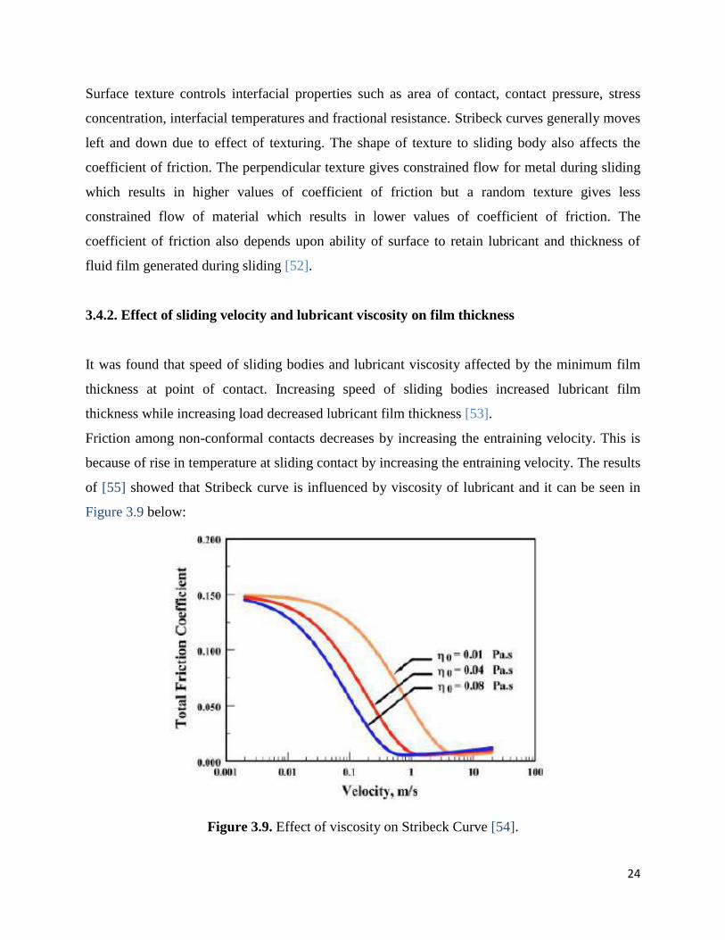
Friction among non-conformal contacts decreases by increasing the entraining velocity. This is
because of rise in temperature at sliding contact by increasing the entraining velocity. The results
of [55] showed that Stribeck curve is influenced by viscosity of lubricant and it can be seen in
Figure 3.9 below:
Figure 3.9. Effect of viscosity on Stribeck Curve [54].

25
It was also noticed that under the specific loads condition, grooves orientation perpendicular to
sliding direction have successful texturing effect. The surface texturing can also effect regimes of
lubrication. Hydrodynamic regime can be extended for a greater load and speed. It was found
that lower coefficient of friction is attained by laser surface texturing when compared with a
polished surfaces. The increase of load carrying capacity and friction reduction particularly at
low speeds is confirmed by experimental work [55].

26
4. Materials and Methods
The minimum film thicknesses (h0) have been calculated for the isothermal elastohydrodynamic
lubrication conditions using the equation of Hamrock and Dowson [56,57] presented below Eq.
(2). This equation applies to any contact, such as linear (flat on ring) and can be used for many
material combinations up to maximum pressures of 3-4 GPa.
𝒉𝒐
𝑹′= 𝟑. 𝟔𝟑 (
𝑼𝜼𝟎
𝑬′𝑹′)
𝟎.𝟔𝟖(𝜶𝑬′)𝟎.𝟒𝟗 (
𝑾
𝑬′𝑹′𝟐)
−𝟎.𝟎𝟕𝟑(1 − 𝑒−0.68𝐾) (2)
Where:
h0 is the minimum film thickness [m];
U is the entraining surface velocity [m/s], i.e. U = (UA + UB)/2, where the subscripts ‘A’ and ‘B’
refer to the velocities of bodies ‘A’ and ‘B’ respectively;
η0 is the viscosity at atmospheric pressure and temperature ‘θ’ of the lubricant [Pas];
E' is the reduced Young's modulus [Pa];
R ' is the reduced radius of curvature [m];
α is the pressure-viscosity coefficient [m2/N];
W is the contact load [N];
k is the ellipticity parameter defined as: k = a/b, where ‘a’ is the semiaxis in the transverse
direction and ‘b’ is the semiaxis in the direction of motion. For line contact k = ∞.
The lubricant fluid used in these calculations is assumed to be compressible and its viscosity-
pressure behaviour is described by the Barus law Eq. (3). However, according with Sargent et al.
[58] the application of this equation to pressures above 0.5 GPa can, lead to serious errors.
𝛈𝐩 = 𝛈𝟎𝐞𝛂𝐩 (3)
Where:
ηp is the lubricant viscosity at pressure ‘p’ and temperature ‘θ’ [Pas];

27
In order to account for surface roughness in the calculation of the film thickness. Tallian [33],
proposed a new parameter characterizing the ratio of the minimum film thickness to the
composite surface roughness, and is defined as:
𝛌 =𝐡𝟎
(𝛔𝐀 𝟐 + 𝛔𝐁
𝟐)𝟎.𝟓 (4)
Where:
σA is the RMS surface roughness of body ‘A’ [m];
σB is the RMS surface roughness of body ‘B’ [m];
λ is the parameter characterizing the ratio of the minimum film thickness to the composite
surface roughness.
4.1. Types of Pattern
4.1.1. Specimens
The steel specimens of quenched and tempered (710 HV) AISI M2 steel were prepared by
machining and polishing to mirror smoothness (Ra = 0.01 μm). The chemical composition can be
seen in Table 4.1. The size of each specimen was ∅20×7.8 mm. All the disc specimens were
textured by wire EDM by positioning it parallel to the surface with three different patterns of
micro-grooves, different in terms of patterned area density. Patterned area density was calculated
by dividing the surface into equal triangles as shown in Figure 4.1. Intersection angle was 60
degrees and width of the grooves (t) were 150 μm, respectively. Patterned area density was
varied by changing the distance between grooves (d).
Table 4.1. Steel chemical composition (in weight %).
Chemical composition C Cr Mn Mo Ni V Si W
AISI M2 1.00 4.15 0.30 5.0 - 1.95 0.30 6.25
AISI 3415 0.17 0.75 0.55 - 3.25 - <0.20 -

28
Figure 4.1. Pattern geometry and dimensions.
The ratio of surface area to the whole area was represented as ratio of the areas of similar
triangles, which, by their properties, is equal to squared coefficient of similarity. Therefore,
patterned area density was calculated as:
𝑨𝒑 = 𝟏 − (𝒃
𝒃+ 𝒕
𝐜𝐨𝐬 (𝜶/𝟐)
)
𝟐
(5)
Where Ap is the pattern area density, b the rhomb width, t the groove width and α the
intersection angle. The distance between grooves can be expressed as d = bcos .
The main feature characteristics of the three textured patterns were measured with white light 3D
scanning microscope and average measured and calculated values, which fully characterize
textured samples are presented in Table 4.2. After EDM texturing, the disc specimens were
polished again to remove uniform grinding marks and achieve similar surface roughness as the
smooth specimen. Figure 4.2 shows the three surface textured patterns with 21, 44 and 65 % area
densities, corresponding to the designation of TLowD, TMediumD and THighD, respectively.

29
Table 4.2. Main features characteristics of the textured disc patterns.
Surface texture pattern TLowD TMediumD THighD
Distance between grooves, d (μm) 1294 603 390
Groove width, t (µm) 142 149 159
Groove depth (µm) 16.3 15.8 17.8
Rhomb width, b (µm) 1331 524 267
Patterned area density, Ap (%) 21 44 65
(a)
(b)
(c)
Fig. 4.2. Micrographs of surface textured patterns: (a) textured with low density-TLowD
(b) textured with medium density-TMediumD and, (c) textured with high density-THighD.

30
4.2. Characterization of samples surface
An example of a 2D profile of a textured surface with low density – TlowD is presented in
Figure 4.3. Figure 4.4 shows area for one cone, the groove depth is approximately 16 µm. It can
also be seen that the groove edges exhibit a perfect round shape and depth.
Figure 4.3. 2D profile of TLowD specimen illustrating the shape and dimensions of typical
micro-grooves.
Figure 4.4. Roughness profile (single cone).
-16
-14
-12
-10
-8
-6
-4
-2
0
2
-0.5 0.5 1.5 2.5 3.5 4.5
μm
mm
-16
-14
-12
-10
-8
-6
-4
-2
0
2
-0.05 0.05 0.15 0.25 0.35 0.45 0.55 0.65 0.75

31
4.3. Calculation of cone area
To calculate area for one honed surface, the whole surface should be divided into trapezes. The
area of all trapezes is calculated and then added. The formula for calculating area of one trapeze
is as follows:
𝐀𝐢 = (𝐘(𝐢 − 𝟏) + 𝐘𝐢) ∗(𝐗𝐢 − 𝐗(𝐢−𝟏)
𝟐 = 1.41 * 10-03 mm. (6)
Patterns were made with EDM technique. Textured samples were grinded afterwards with SiC
paper grit 4000 to remove grinding marks.
4.4. Experimental procedure
Block on ring sliding test tribometer used in this testing is shown in Figure 4.5.
Figure 4.5. Block on ring sliding test tribometer used for testing.

32
Friction tests were carried out using a block-on-ring friction machine under unidirectional
sliding. The Schematic diagram of the block-on-ring sliding test tribometer can be seen in Figure
4.6. During test stationary block consisting of the four different test specimens three textured and
one un-textured was pressed with a constant load of 40 N against a rotating ring. The rotating
ring is 150 mm in diameter and 12 mm in thickness and is made of alloyed carbon steel (3415,
AISI). Specimens were positioned 90° to the ring’s axis of rotation. The chemical composition of
the rotating ring is given in Table 4.1. The initial surface roughness of rotating ring was Ra =
0.04 µm. During tests, normal load and friction force between the sliding surfaces of the block
and ring were monitored, thus computing values of friction coefficient. The effect of sliding
speed and the patterned area density on the friction behaviour were investigated. The friction
tests were conducted on low density texture, medium density texture and high density texture
discs at a normal load of 40 N for the six different linear sliding speeds mentioned below.
According to the Hertzian stress theory, this applied load corresponds to a nominal contact
pressure of approximately 0.04 GPa. However, the real contact area decreased due to the grooves
for a pattern area ratio between 21 and 65 %, leading to an increase real contact pressure. Results
were then compared to un-textured case and presented in the form of coefficient of friction as a
function of textured patterned density. Tests were carried out at angular speeds of 4, 13, 32, 64,
127 and 162 rpm, corresponding to linear sliding speeds of 0.03, 0.1, 0.25, 0.5, 1.0 and 1.27 m/s,
respectively. The number of turns was set to 100, 250, 500, 1000, 1000 and 1000, respectively.
During testing, three different oils were used as lubricants: ISO VG 46 (PAO 8, ν40 = 46
mm2/s), ISO VG 150, synthetic based products formulated with a combination of PAO (ν40 =
150 mm2/s) and ISO VG 320, also formulated with a combination of synthetic based products
and PAO (ν40 = 320 mm2/s). The main oil properties can be seen in Table 4.3. The lubricating
conditions were set to fully flooded contact. Each test was started with ultrasonically cleaned and
dried disc and block surfaces. The atmosphere surrounding the test was room air of 22 ± 20C and
relative humidity of 58 ± 10%. Each friction test was carried out for the sliding distance of 47,
118, 236, 471, 471 and 469 m (corresponding to the running conditions defined above), during
which the steady-state conditions were reached. Error bars were estimated from standard
deviations of steady coefficient of friction values.

33
Fig. 4.6. Schematic diagram of the block-on-ring sliding test tribometer.
Table 4.3. Lubricant properties.
Oil Kinematic viscosity (mm2/s) @ 400C Density (g/cm3) @ 150C
ISO VG 46 46 0.830
ISO VG 150 150 0.872
ISO VG 320 320 0.903
Load
Friction
Ro
tati
on

34
5. Results and discussion
5.1. Effect of lubricant viscosity and pattern area density on COF
5.1.1. ISO VG 46 (PAO8)
Figure 5.1 shows the steady state values of coefficient of friction for un-textured and textured
surfaces lubricated with PAO8 for the six different sliding speeds. It can be seen that for all the
samples, the friction shows a clear evolution from a high coefficient of friction values at low
sliding speeds to a lower friction values at higher sliding speeds. The curves showed that
textured surfaces had no beneficial effect in reducing friction at low sliding speeds (from 0.03 up
to 0.25 m/s). However, the textured surfaces start to show positive effect at higher sliding speeds
(from 0.5 up to 1.27 m/s). It can be seen that for higher sliding speeds, the beneficial effect of the
grooved surface texturing becomes larger as the texture density decreases. The curve for high
density textured sample has the highest coefficient of frictions while the curve of medium
density textured sample has coefficient of frictions in between low density and high density
textured samples.
In a previous study [25,26], It was also found that the tribological behaviour depends on the
depth of the micro-dimples as well as on the operating conditions with the beneficial effect
becoming larger for higher sliding speeds. Moreover, the patterns with micro-dimples have
closed textured surfaces and they are supposed to retain the lubricant and to generate
hydrodynamic pressure easier than micro-grooves. It was also observed that patterns with micro-
grooves with low and medium densities used in this study seem to play a positive role in
preventing side leakage of the lubricating oil and decreasing the coefficient of friction in relation
to the smooth surface. This could be explained due to the geometry of the grooves that have
interconnected rhombic form instead of a linear and open geometry.

35
Figure 5.1. Variation in coefficient of friction with sliding speed for un-textured and textured
surfaces lubricated with ISO VG 46: 40 = 46 mm2/s and at 40 N applied load.
5.1.2. High viscosity oil – ISO VG 320
Figure 5.2 shows the variation of the steady-state coefficient of friction for un-textured and
textured surfaces lubricated with ISO VG 320, for the six different sliding speeds (0.03, 0.1,
0.25, 0.5, 1.0 and 1.27 m/s).
0.00
0.02
0.04
0.06
0.08
0.10
0.12
0.14
0.16
0.00 0.20 0.40 0.60 0.80 1.00 1.20 1.40
Co
eff
icie
nt
of
Frti
ctio
n
Sliding speed (m/s)
un-textured
TLowD
TMediumD
THighD

36
Figure 5.2. Variation in coefficient of friction with sliding speed for un-textured and textured
surfaces lubricated with ISO VG 320: 40 = 320 mm2/s (FN = 40 N).
5.1.3. Medium viscosity oil – ISO VG 150
Figure 5.3 shows the variation of the steady-state coefficient of friction for un-textured and
textured surfaces lubricated with ISO VG 150, for the six different sliding speeds (0.03, 0.1,
0.25, 0.5, 1.0 and 1.27 m/s).
0.00
0.02
0.04
0.06
0.08
0.10
0.12
0.14
0.16
0.00 0.20 0.40 0.60 0.80 1.00 1.20 1.40
Co
eff
icie
nt
of
Frti
ctio
n
Sliding speed (m/s)
un-textured
TLowD
TMediumD
THighD

37
Figure 5.3. Variation in coefficient of friction with sliding speed for un-textured and textured
surfaces lubricated with ISO VG 150: = 150 mm2/s (FN = 40 N).
5.2. Comparison between different lubricant viscosities
5.2.1. Comparison between low viscosity (ISO VG 46) and high viscosity (ISO VG 320) oil
Figure 5.4 shows the comparison of coefficient of friction values for un-textured and textured
surfaces lubricated with ISO VG 46 and ISO VG 320 for the six different sliding speeds. It can
be seen in Figure 5.4 that curves change drastically with increasing oil viscosity from 46 to 320
mm2/s. Two main effects can be observed. First, transition from a boundary, mixed and
hydrodynamic lubrication regime occurred at lower sliding speeds for higher viscosity (320
mm2/s) oil. Second, the slope in the hydrodynamic lubrication regime increases with increasing
viscosity and it can be seen for dashed lines shown in Figure 5.4.
0.00
0.02
0.04
0.06
0.08
0.10
0.12
0.14
0.16
0.00 0.20 0.40 0.60 0.80 1.00 1.20 1.40
Co
eff
icie
nt
of
Frti
ctio
n
Sliding speed (m/s)
un-textured
TLowD
TMediumD
THighD

38
It was observed for higher viscosity oil ISO VG 320 (curves shown by dashed lines in Figure
5.4) that at lower sliding speeds, specimens showed lower coefficient of friction than specimens
lubricated with lower viscosity oil ISO VG 46 (shown by solid lines in Figure 5.4). It can be
seen for both lubricants that coefficient of friction is increasing as the pattern area density
increases from low density texture (TLowD) to medium density texture (TMediumD) and up to
high density texture (THighD). The reason for this is, as pattern area density increases, the real
contact area decreases due to presence of grooves and this lead to an increase of the real contact
pressure and increasing coefficient of friction.
The smooth specimen is showing the lowest coefficient of friction of all specimens. As we
moved towards higher sliding speeds the differences between the coefficient of friction for un-
textured and textured discs become smaller due to the increase in lubricant viscosity, resulting in
increasing lubricant film thickness as sliding speed increases.
Figure 5.4. Variation in coefficient of friction with sliding speed for un-textured and textured
surfaces lubricated with ISO VG 46: 0 = 46 mm2/s and ISO VG 320: = 320 mm2/s (FN = 40
N).
0.00
0.02
0.04
0.06
0.08
0.10
0.12
0.14
0.16
0.00 0.20 0.40 0.60 0.80 1.00 1.20 1.40
Co
effi
cien
t o
f Fr
tict
ion
Sliding speed (m/s)
ISO VG 46 un-textured ISO VG 320 un-textured
ISO VG 46 TLowD ISO VG 320 TLowD
ISO VG 46 TMediumD ISO VG 320 TMediumD
ISO VG 46 THighD ISO VG 320 THighD

39
5.2.2. Comparison between low viscosity (ISO VG 46) and medium viscosity (ISO VG 150)
oil
Figure 5.5 shows the steady-state coefficient of friction for un-textured and textured surfaces
lubricated with ISO VG 46 and ISO VG 150, for the six different sliding speeds. At low sliding
speed from 0.03 m/s up to 0.1 m/s, the smooth surface showed lower coefficient of friction then
all the textured surfaces and with the coefficient of friction increasing as the pattern area density
increases. However, as we move towards higher sliding speeds from 0.1 up to 1 m/s an inversion
occurred with the textured pattern with lower density (dashed orange line), showing lower
coefficient of friction than the smooth surface (dashed blue line).
Again, the differences between the coefficient of friction for un-textured and textured discs at
higher sliding speeds become smaller due to the increase in lubricant viscosity, resulting in
increasing lubricant film thickness as sliding speed increases.

40
Figure 5.5. Variation in coefficient of friction with sliding speed for un-textured and textured
surfaces lubricated with ISO VG 46: = 46 mm2/s and ISO VG 150: = 150 mm2/s
(FN = 40 N).
5.3. Stribeck curves
Since we used three different lubricants ISO VG 46 (PAO8), ISO VG 320 and ISO VG 150 for
the four different specimens tested (one un-textured and three textured). It is possible to build
Stribeck curves by normalizing the six different sliding speeds (0.03, 0.1, 0.25, 0.5, 1.0 and 1.27
m/s) to the adimensional parameter sliding speed*viscosity/load. Figure 5.6 shows the Stribeck
curve for the smooth sample where is possible to see the different data points obtained for the
three different lubricant viscosities (blue, red and green data points).
0.00
0.02
0.04
0.06
0.08
0.10
0.12
0.14
0.16
0.00 0.20 0.40 0.60 0.80 1.00 1.20 1.40
Co
effi
cien
t o
f Fr
tict
ion
Sliding speed (m/s)
ISO VG 46 un-textured ISO VG 150 un-textured
ISO VG 46 TLowD ISO VG 150 TLowD
ISO VG 46 TMediumD ISO VG 150 TMediumD
ISO VG 46 THighD ISO VG 150 THighD

41
Figure 5.6. Variation in coefficient of friction with sliding speed*viscosity/load for un-textured
surface lubricated with ISO VG 46: = 46 mm2/s (PAO8), ISO VG 150: = 150 mm2/s and
ISO VG 320: = 320 mm2/s (FN = 40 N).
The same procedure was repeated to obtain Stribeck curves for textured specimens with low,
medium and high textured density. In this way, all set of data points were joined together on one
figure to get four stribeck curves for untextured and textured discs. Figure 5.7 shows data points
for Stribeck curves for all specimens, both textured and un-textured, lubricated with three
different lubricants ISO VG 46: 40 = 46 mm2/s, ISO VG 150: 40 = 150 mm2/s and ISO VG 320:
40 = 320 mm2/s (FN = 40 N). The spread of data points is due to the use of different lubricant
viscosities. Average Stribeck curves were obtained from these points and are shown in Figure
5.8. It can be seen in Figure 5.8 that lower density textured sample showed beneficial effects in
range of medium oil viscosity (ISOVG 150).
The relation sliding speed*viscosity/ load in range from 0.0005 to 0.0035 shows beneficial
effects of using texturing. So, beneficial effect of texturing, here is only for using low pattern
0.0000
0.0200
0.0400
0.0600
0.0800
0.1000
0.1200
0.1400
0 0.001 0.002 0.003 0.004 0.005 0.006 0.007 0.008 0.009 0.01
Co
effi
cien
t o
f fr
icti
on
speed*viscosity/load
Smooth sample
PAO8
ISOVG 320
ISOVG 150

42
area density. The Figure 5.7 can be divided in three regions. Firstly, by using ISO VG 46, no
effect of texturing was seen (in regions from 0 to 0.0005), with coefficient of friction increasing
as textured density increases. Secondly, by using medium density oil ISOVG 150 (in regions
from 0.0005 to 0.0035), lower density textured disc showed the lowest values of coefficient of
friction in comparison to smooth and other textured specimens. Medium density textured sample
has coefficient of friction in between smooth specimen and high density texturized sample.
Finally, by using high viscosity oil, ISO VG 320 (in region between 0.0035 and 0.01), texturing
again showed no beneficial effects. Also, by increasing higher viscosity oil, a thick oil film is
formed between sliding bodies and all texturized samples has almost same values of coefficient
of friction in this region.
Figure 5.7. Variation in coefficient of friction with sliding speed*viscosity/load for textured and
un-textured surfaces lubricated with ISO VG 46: = 46 mm2/s (PAO8), ISO VG 150: = 150
mm2/s and ISO VG 320: 0 = 320 mm2/s (FN = 40 N).
0.0000
0.0200
0.0400
0.0600
0.0800
0.1000
0.1200
0.1400
0.1600
0 0.001 0.002 0.003 0.004 0.005 0.006 0.007 0.008 0.009 0.01
Co
eff
icie
nt
of
fric
tio
n
speed*viscosity/load
Smooth sample
High density texturization
Low density texturization
Medium density texturization

43
Figure 5.8. Average Stribeck curves for textured and un-textured surfaces lubricated with ISO
VG 46: = 46 mm2/s (PAO8), ISO VG 150: = 150 mm2/s and ISO VG 320: = 320
mm2/s (FN = 40 N).
5.4. Effect of sliding velocity and lubricant viscosity on transitions in lubrication regimes
Table 5.1 shows the calculated values for the λ ratio of the film thickness to the composite
surface roughness) for the three different lubricant viscosities. As long as the λ ratio is greater
than unity the film thickness exceeds the mean surface roughness and severe wear is minimized.
When λ is less than one as observed for PAO8 at 0.03 m/s sliding speed, the film thickness is
smaller than the asperity height and the boundary lubrication regime exists. When λ becomes
greater than five, values indicated by dark blue in the table, the highest asperities will no longer
contact and ideal full film or hydrodynamic lubrication exists. In between these two extremes
mixed lubrication regime exists, because λ is greater than one and less than five and values are
indicated by blue in the table.
0
0.02
0.04
0.06
0.08
0.1
0.12
0.14
0.16
0 0.001 0.002 0.003 0.004 0.005 0.006 0.007 0.008 0.009 0.01
CO
F
Sliding speed*viscosity/load
Smooth Sample
High density texturization
Low density texturization
Medium density texturization

44
Table 5.1. Specific film thickness (λ) values for six different sliding speeds and three different
lubricant viscosities, showing the variation in the lubrication regime (boundary - light blue: λ <
1; mixed - blue: 1< λ < 5 and hydrodynamic - dark blue λ > 5).
The effect of increasing the lubricant viscosity contributes to that the transition from a boundary,
mixed and hydrodynamic lubrication regime occur at lower speeds. It can be seen in Table 5.1
for PAO8, all the lubrication regimes exist within these range of sliding speeds. The transition
from boundary to mixed lubrication occurs between 0.03 and 0.1 m/s, while from mixed to
hydrodynamic lubrication, the transition occurred between 0.5 and 1.0 m/s. For higher viscosity
oil, ISO VG 320 only mixed and hydrodynamic lubrication are found with the transition from
mixed to hydrodynamic lubrication occurring between 0.03 and 0.1 m/s. Minimum film
thickness is also given in the Table 5.1. It can be notice that minimum film thickness increases
with increasing sliding speed for each oil and for higher viscosity oil ISO VG 320 oil film
thickness has the highest values among all lubricants.
Sliding speed (m/s)
0.03 0.1 0.25 0.5 1.0 1.27
PAO8 0.7 1.6 3.0 4.7 7.6 9.0
h0 (m) 3.37E-08
7.64E-08
1.42E-07
2.28E-07
3.65E-07
4.30E-07
ISO VG 150 1.6 3.6 6.8 10.8 17.4 20.4
h0 (m) 7.69E-08
1.74E-07
3.25E-07
5.21E-07
8.34E-07
9.82E-07
ISO VG 320 2.7 6.2 11.6 18.6 29.8 35.0
h0 (m) 1.32E-07
2.99E-07
5.57E-07
8.93E-07
1.43E-06
1.68E-06
45
6. Conclusions
This work showed the role played by surface texturing in both hydrodynamic and
boundary/mixed regime and its potential to reduce friction. This study focused on
textured patterns of grooves with three different pattern area densities. The effect of
sliding speed and lubricant viscosity on friction, was studied and compared with un-
textured case.
Contact conditions were found to be an important factor in terms of tribological
behaviour of textured surfaces. One of the main parameters governing friction behaviour
is the contact pressure. The real pressure value can indeed be higher than theoretical
calculated (0.04GPa). In textured specimens, real contact area is only a part of the contact
surface, due to the higher textured density.
Tribological behaviour of textured surfaces was found to greatly depend on the textured
pattern density as well as on the dominant lubrication mode (operating conditions).
For lower viscosity oil (ISO VG 46) the beneficial effect of micro-grooves becomes
larger with a decrease in groove density as well as for higher sliding speeds (0.5, 1.0 and
1.27 m/s).
For medium viscosity oil (ISO VG 150), all the textured specimens showed lower
coefficient of friction than smooth specimen for higher sliding speeds (1.0 and 1.27 m/s).
For higher viscosity oil (ISO VG 320), textured specimens did not show any beneficial
effect in reduction friction.
For higher viscosity oils (e.g.: ISO VG 320), the transition from boundary to mixed and
to hydrodynamic lubrication regimes occurred at lower speeds. Additionally, the slope in
the hydrodynamic lubrication increases with increasing viscosity.
Average Stribeck curves, considering the three different lubricant viscosities and
normalizing the sliding speed to the adimensional parameter sliding speed*viscosity/load
showed that the beneficial effect of surface texturing occurred at the mixed lubrication
regime.

46
Biblography
[1] Hsu, S. Implementing Agreement for a Program of Research and Development on Advanced
Materials for Transportation Applications. IEA, Strategic Plan. Washington : s.n., 2008.
[2] Etsion, I. Improving tribological performance of mechanical components by laser surface
texturing. Tribol. Lett. 2004, Vol. 17, pp. 733-737.
[3] Suh, N.P., Mosleh, M. and Howard, P.S. Control of friction. Wear. 1994, Vol. 175, pp. 151-
158.
[4] Hu, Z.M. and Dean, T.A. A study of surface topography, friction and lubricants in metal
forming. Int. Journal of Machine Tools & Manufacture. 2000, Vol. 40, pp. 1637-1649.
[5] Svahn, F., Kassman-Rudolphi, A. and Wallen, E. The influence of surface roughness on
friction and wear of machine element coatings. Wear. 2003, Vol. 254, pp. 1092-1098.
[6] Tayebi, N. and Polycarpou, A.A. Modeling the effect of skewness and kurtosis on the static
friction coefficient of rough surfaces. Tribology International. 2004, Vol. 37, pp. 491-505.
[7] Santner, E., et al. Effects of friction on topography and vice versa. Wear. 2006, Vol. 261, pp.
101-106.
[8] Meine, K., et al. The influence of roughness on friction: Part I: The influence of a single step.
Wear. 2002, Vol. 253, pp. 725-732.
[9] Meine, K., et al. The influence of roughness on friction: Part II: The influence of multiple
steps. Wear. 2002, Vol. 253, pp. 733-738.
[10] Wang, W., et al. Effect of surface roughness parameters on mixed lubrication
characteristics. Tribology International. 2006, Vol. 39, pp. 522-527.
[11] Poon, C. Y. and Bhushan, B. Comparison of surface roughness measurements by stylus
profiler, AFM and non-contact optical profiler. wear. 1995, Vol. 190, pp. 76-88.
[12] Pettersson, U. and Jacobson, S. Friction and wear properties of micro textured DLC coated
surfaces in boundary lubricated sliding. Tribol. Lett. 2004, Vol. 17, pp. 553-559.
[13] Y. Kligerman, I. E. (July 2005). Improving Tribological Performance of Piston Rings by
Partial Surface Texturing. 1-7.
[14] Yuankai Zhou, H. Z. (n.d.). Influence of surface roughness on the friction property of
textured surface. Advances in mechanical engineering, 1-9.

47
[15] Gualtieri, E. (2004). Improving tribological properties of steels by surface texturing and
coating. PhD courses in physics.
[16] Ramesh, A. (2012). Friction characteristics of microtextured surfaces under hydrodynamic
lubrication. Thesis
[17] Daniela G Coblas, Aurelian Fatu, Abdelghani Maoui, Mohamed Hajjam. “Manufacturing
textured surfaces: State of art and recent developments”: Journal of Engineering Tribology, July
10, 2014
[18] Hsu, S. (2008). Integrated Surface Engineering for Improving Energy Efficiency. NTEL.
[19] Halperin, I. E. (2008). A Laser Surface Textured Hydrostatic Mechanical Seal. Tribology
Transactions, 1-6.
[20] Kligerman, Y. (2001). Analysis of Hydrodynamic effects in surface textured circumferential
gas seal. STLE, 472-478.
[21] Chin Y. Poon, B. B. (1994). Comparison of surface roughness measurements by stylus
profiler, AFM and non-contact optical profiler. Wear.
[22] J. Oksanen, T. H. (2012). Tribological properties of laser textured and DLC coated surfaces
with solid lubricants. 10-14.
[23] (Blau, Use of Textured Surfaces to Mitigate Sliding Friction and Wear of Lubricated and
Non Lubricated contacts, 2012)
[24] Krishan Kumar Gupta, R. K. (2013). Study on Effect of Surface Texture on the Performance
of Hydrodynamic Journal Bearing. International Journal of Engineering and Advanced
Technology (IJEAT).
[25] Wang X, Kato, K., Adachi K. and Aizawa K., “The effect of laser texturing of SiC surface
on the critical load for the transition of water lubrication mode from hydrodynamic to mixed”.
Tribology International 34, 2001, 703–711.
[26] Wakuda M., Yamauchi Y., Kanzaki S., Yasuda Y., “Effect of surface texturing on friction
reduction between ceramic and steel materials under lubricated sliding contact”. Wear 254, 2003,
356–363.
[27] Andriy Kovalchenkoa , Oyelayo Ajayia, Ali Erdemira , George Fenskea , Izhak Etsionb.
“The effect of laser surface texturing on transitions in lubrication regimes during unidirectional
sliding contact”: Tribology International 38 (2005) 219–225

48
[28] A. M. Kovalchenko. “State of investigations of surface texturing for tribological
characteristics improvement of the friction units (A Review)”: Institute for Problems of Materials
Science National Academy of Science of Ukraine: УДК 621.891:531.43
[29] Ronen A., Etsion I. and Kligerman Y. (2001) Friction-reducing surface-texturing in
reciprocating automotive components, Tribology Transactions, Vol. 44, pp. 359–366.
[30] Kligerman Y., Etsion I. and Shinkarenko A. (2005) Improving tribological performance of
piston rings by partial surface texturing, Journal of Tribology-Transactions of the ASME, Vol.
127, pp. 632–638.
[31] Ryk G., Kligerman Y., Etsion I. and Shinkarenko A. (2005) Experimental investigation of
partial laser surface texturing for piston-ring friction reduction, Tribology Transactions, Vol. 48,
pp. 583–588.
[32] Ryk G. and Etsion I. (2006) Testing piston rings with partial laser surface texturing for
friction reduction, Wear, Vol. 261, pp. 792–796.
[33] Etsion I., Halperin G. and Becker E. (2006) The effect of various surface treatments on
piston ring scuffing resistance, Wear, Vol. 261, pp. 785–791.
[34] Ryk, G., Kligerman, Y., and Etsion, I., Experimental Investigation of Laser Surface
Texturing for Reciprocating Automotive Components, STLE Tribology Transactions, Vol. 45,
No. 4, 2002, pp. 444-449.
[35] Vijay K. Patel, Hiren P.Patel, Hitesh J. Yadav, Prof. V.R.Patel. “Experimental investigation
of laser surface texturing on piston rings for friction reduction and improving fuel efficiency-a
review study, International Journal of Advanced Engineering Technology,1-5.
[36] Patel Kalpeshkumar P. (2015). Effect of different parameter of LST: an overview. IJEDR,
1-5.
[37] Narita, K. (2012). Tribological Properties of Metal V-Belt Type CVT Lubricant. Advances
in Tribology, 1-8.
[38] Antoszewski Bogdan. Mechanical Seals With Sliding Surface Texture – Model Fluid Flow
and Some Aspects of the Laser Forming of the Texture: Procedia Engineering 39 ( 2012 ) 51 –
62
[39] Etsion I., Halperin G., Brizmer V. and Kligerman Y. (2004) Experimental investigation of
laser surface textured parallel thrust bearings, Tribology Letters, Vol. 17, pp. 295–300.

49
[40] Marian V. G., Kilian M. and Scholz W. (2007) Theoretical and experimental analysis of a
partially textured thrust bearing with square dimples, Proceedings of the Institution of
Mechanical Engineers Part J-Journal of Engineering Tribology, Vol. 221, pp. 771–778.
[41] Cupillard S., Glavatskih S. and Cervantes M. J. (2008) Computational fluid dynamics
analysis of a journal bearing with surface texturing, Proceedings of the Institution of Mechanical
Engineers Part J-Journal of Engineering Tribology, Vol. 222, pp. 97–107.
[42] Glavatskih S. B., McCarthy D. M. C. and Sherrington I. (2005) Hydrodynamic performance
of a thrust bearing with micropatterned pads, Tribology Transactions, Vol. 48, pp. 492–498.
[43] Lu X. B. and Khonsari M. M. (2007) An experimental investigation of dimple effect on the
Stribeck curve of journal bearings, Tribology Letters, Vol. 27, pp. 169–176.
[44] Borghi A., Gualtieri E., Marchetto D., Moretti L. and Valeri S. (2008) Tribological effects
of surface texturing on nitriding steel for highperformance engine applications, Wear, Vol. 265,
pp. 1046–1051.
[45] Wan Y. and Xiong D. S. (2007) Influence of laser surface texturing on tribological
performance of mechanical components, Journal of Central South University of Technology,
Vol. 14, pp. 79–82.
[46] Rashwan, O. (2013). Micro Surface Texturing for Friction Control. Electronic Theses and
Dissertations, 3-196.
[47] Mihir Kumar Ghosh, Bankim Chandra Majumdar, Mihir Sarangi. Theory of lubrication,
Tata McGrawhill education Private Limited (December 14, 2012), PP (3-4).
[48] Kovalchenko A., Ajayi O., Erdemir A., Fenske G. and Etsion I. (2004) The effect of laser
texturing of steel surfaces and speed-load parameters on the transition of lubrication regime from
boundary to hydrodynamic, Tribology Transactions, Vol. 47, pp. 299-307.
[49] Hsu, S. M. Surface Texturing: Principles and Design. National Institute of Standards &
Technology. Maryland, USA : s.n., 2006
[50] Stephens, R. and L., Siripuram. Effect of Deterministic Asperity Geometry on
Hydrodynamic Lubrication. ASME Journal of Tribology.2004, Vol.126, pp. 527-534
[51] Etsion, I., Kligerman, Y. and Halperin, G. STLE Tribol. Trans. 1999, Vol. 42, p. 511.
[52] Pradeep Kumar C, Pradeep L. Menezes, and Satish V. Kailas. “Role of surface texture on
friction and wear under boundary lubricated conditions”:International Conference on Industrial
Tribology – 2006

50
[53] Peter M. Thompson, William R. Jones, Jr., Mark J. Jansen, Joseph M. Prahl. “The Effect of
Sliding Speed on Film Thickness and Pressure Supporting Ability of a Point Contact Under Zero
Entrainment . Velocity Conditions”: Society of Tribologists and Lubrication Engineers Orlando,
Florida, May 20-24, 2001
[54] Ing. Fadi Ali. “Effect of surface texturing on friction and film thickness under starved
lubrication conditions”: Brno university of technology, ISBN 80-214- ISSN 1213-4198.
[55] Morris, Nicholas J., Rahnejat, Homer, Rahmani, Ramin. “Tribology of partial pad journal
bearings with textured surfaces”: The Austrian Tribology Society, 2011.
[56] B.J. Hamrock and D. Dowson, Ball Bearing Lubrication, The Elastohydrodynamics of
Elliptical Contacts John Willey & Sons, 1981.
[57] B.J. Hamrock and D. Dowson, Isothermal Elastohydrodynamic Lubrication of Point
Contacts, Part III – Fully Flooded Results, Transactions ASME, Journal of Lubrication
Technology, Vol. 99, 1977, pp. 264-276.
[58] L.B. Sargent Jr, Pressure-Viscosity Coefficients of Liquid Lubricants, ASLE Transactions,
Vol. 26, 1983, pp. 1-10.

51