Embed Size (px)
Citation preview
ww.sciencedirect.com
i n t e rn a t i o n a l j o u r n a l o f h y d r o g e n en e r g y 4 1 ( 2 0 1 6 ) 2 0 9 6e2 1 0 4
Available online at w
ScienceDirect
journal homepage: www.elsevier .com/locate/he
Effect of gasoline pool fire on liquid hydrogenstorage tank in hybrid hydrogenegasoline fuelingstation
Junji Sakamoto a, Jo Nakayama b,c, Toyoaki Nakarai a, Naoya Kasai b,d,Tadahiro Shibutani a,d, Atsumi Miyake a,b,d,*
a Center for Risk Management and Safety Sciences, Yokohama National University, 79-5 Tokiwadai, Hodogaya-ku,
Yokohama, Kanagawa 240-8501, Japanb Faculty of Environment and Information Sciences, Yokohama National University, 79-7 Tokiwadai, Hodogaya-ku,
Yokohama, Kanagawa 240-8501, Japanc JSPS Research Fellow, Japand Institute of Advanced Sciences, Yokohama National University, 79-5 Tokiwadai, Hodogaya-ku, Yokohama,
Kanagawa 240-8501, Japan
a r t i c l e i n f o
Article history:
Received 2 September 2015
Received in revised form
31 October 2015
Accepted 6 November 2015
Available online 28 November 2015
Keywords:
Hydrogen fueling station
Gasoline pool fire
Thermal radiation
Liquid hydrogen storage tank
Domino effect
Safety distance
Abbreviations: FCV, fuel cell vehicle; HAZagement Agency of the Ministry of Internalroom temperature.* Corresponding author. Center for Risk Man
ku, Yokohama, Kanagawa 240-8501, Japan. TE-mail address: [email protected] (A. Miy
http://dx.doi.org/10.1016/j.ijhydene.2015.11.039
0360-3199/Copyright © 2015, The Authors. Publishe
CC BY license (http://creativecommons.org/licenses
a b s t r a c t
Multiple-energy-fueling stations, which can supply several types of energy such as gaso-
line, CNG, and hydrogen, could guarantee the efficient use of space. To guide the safety
management of hybrid hydrogenegasoline fueling stations, which utilize liquid hydrogen
as an energy carrier, the scale of gasoline pool fires was estimated using the hazard
assessment tool Toxic Release Analysis of Chemical Emissions (TRACE). Subsequently, the
temperature and the stress due to temperature distribution were estimated using ANSYS.
Based on the results, the safety of liquid hydrogen storage tanks was discussed. It was
inferred that the emissivity of the outer material of the tank and the safety distance be-
tween liquid hydrogen storage tanks and gasoline dispensers should be less than 0.2 and
more than 8.5 m, respectively, to protect the liquid hydrogen storage tank from the gas-
oline pool fire. To reduce the safety distance, several measures are required, e.g. additional
thermal shields such as protective intumescent paint and water sprinkler systems and an
increased slope to lead gasoline off to a safe domain away from the liquid hydrogen storage
tank.
Copyright © 2015, The Authors. Published by Elsevier Ltd on behalf of Hydrogen Energy
Publications, LLC. This is an open access article under the CC BY license (http://
creativecommons.org/licenses/by/4.0/).
ID, hazard identification study; CE, cold evaporator; FDMA, Japan Fire and Disaster Man-Affairs and Communications; TRACE, Toxic Release Analysis of Chemical Emissions; R.T.,
agement and Safety Sciences, Yokohama National University, 79-5 Tokiwadai, Hodogaya-el./fax: þ81 45 339 3993.ake).
d by Elsevier Ltd on behalf of Hydrogen Energy Publications, LLC. This is an open access article under the
/by/4.0/).
i n t e r n a t i o n a l j o u r n a l o f h y d r o g e n en e r g y 4 1 ( 2 0 1 6 ) 2 0 9 6e2 1 0 4 2097
Introduction
Hydrogen has been considered a promising energy carrier
from the viewpoint of reduction in carbon dioxide emissions
and efficient storage and transportation of energy. Moreover,
hydrogen could be produced using renewable energy sources
such as wind or solar energy, in which case it is referred to a
renewable hydrogen or green hydrogen [1].
One of the rising technologies that utilize hydrogen is the
fuel cell vehicle (FCV). A Japanese motor corporation has been
selling commercial FCVs since December 2014, and other
companies are poised to enter the FCV market as well.
Therefore, it is necessary to establish hydrogen infrastructure,
particularly hydrogen fueling stations. Specific safety mea-
sures and over-conservative approaches might increase the
operational costs considerably. Thus, to make hydrogen
fueling stations more economical, it is necessary to optimize
these safety measures.
Many researchers have conducted risk assessments and
analyses with respect to hydrogen fueling stations [2e20].
However, the characteristics of these stations differ depend-
ing on the country and location. Because each country has its
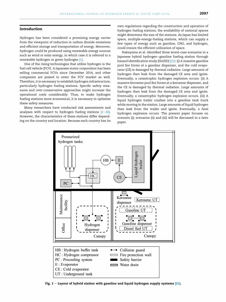
Fig. 1 e Layout of hybrid station with gasoline
own regulations regarding the construction and operation of
hydrogen fueling stations, the availability of national spaces
might determine the size of the stations. As Japan has limited
space, multiple-energy-fueling stations, which can supply a
few types of energy such as gasoline, CNG, and hydrogen,
could ensure the efficient utilization of space.
Nakayama et al. identified three worst-case scenarios in a
Japanese hybrid hydrogenegasoline fueling station through
hazard identification study (HAZID) [21]: (i) Amassive gasoline
pool fire forms at a gasoline dispenser, and the cold evapo-
rator (CE) is damaged by thermal radiation. Large amounts of
hydrogen then leak from the damaged CE area and ignite.
Eventually, a catastrophic hydrogen explosion occurs. (ii) A
massive kerosene pool fire forms at a kerosene dispenser, and
the CE is damaged by thermal radiation. Large amounts of
hydrogen then leak from the damaged CE area and ignite.
Eventually, a catastrophic hydrogen explosion occurs. (iii) A
liquid hydrogen trailer crashes into a gasoline tank truck
whilemoving in the station. Large amounts of liquid hydrogen
then leak from the trailer and ignite. Eventually, a fatal
hydrogen explosion occurs. The present paper focuses on
scenario (i); scenarios (ii) and (iii) will be discussed in a later
paper.
and liquid hydrogen supply systems [21].

Fig. 2 e Relative positions of liquid hydrogen storage tank,
safety barrier, and gasoline dispenser.
i n t e rn a t i o n a l j o u r n a l o f h y d r o g e n en e r g y 4 1 ( 2 0 1 6 ) 2 0 9 6e2 1 0 42098
Japan's High Pressure Gas Safety Act requires a 2-m-high
Table 1 e Properties of gasoline and pool fire.
Chemicalcomposition [mol%]
Gasoline density[g/cm3]
Gasoline flow rate[L/min]
Octane 87.7 and n-
heptane 12.3
0.61 50
safety barrier to be installed in the hybrid hydrogenegasoline
station to cover the valves. Unfortunately, a 10-m-high liquid
hydrogen storage tank would not be covered by this safety
Fig. 3 e Finite element model and mesh: (a) gasoline pool
fire; (b) safety barrier; (c) liquid hydrogen storage tank.
barrier. Thus, a pool fire of gasoline or kerosenewould directly
affect a liquid hydrogen storage tank. The Japan Fire and
Disaster Management Agency (FDMA) of the Ministry of In-
ternal Affairs and Communication [22] has recommended a
3.9 m safety distance between liquid hydrogen storage tanks
and gasoline dispensers. This safety distance was determined
considering two main assumptions. One is that the outer
material of the tank has no temperature distribution and is
uniformly heated. The other is that the safety measures can
function properly at 650 �C to keep the internal pressure
constant within tolerance levels. Based on these two as-
sumptions, the safety distance was calculated to ensure that
the temperature due to pool fire thermal radiation would not
reach 650 �C within 30 min. However, temperature distribu-
tions generate thermal stress and cause tanks to fracture
more easily. Thus, it is important to consider not only the
strength decrease due to high temperatures but also the
thermal stress due to temperature distribution. Although
several researchers have conducted pool fire analyses
[19,20,23e29], they have focused on temperature rather than
temperature distribution.
In this study, to aid the safety management of hybrid
hydrogenegasoline fueling stations, the temperature and
thermal stress due to temperature distribution were analyzed
using the codes Toxic Release Analysis of Chemical Emissions
(TRACE) and ANSYS. Based on the analysis results, the safety
of liquid hydrogen storage tanks was discussed.
Worst accident scenario
Fig. 1 shows the layout of a hybrid hydrogenegasoline fueling
station. Asmentioned in the previous section, two of the three
worst-case scenarios are due to pool fires of gasoline or
kerosene. In these scenarios, a massive gasoline/kerosene
pool fire forms at a gasoline/kerosene dispenser, and the CE is
damaged by thermal radiation. Large amounts of hydrogen
then leak from the damaged CE area and ignite. The CE in the
paper published by Nakayama et al. [21] indicates the liquid
hydrogen storage tank. Eventually, a catastrophic hydrogen
explosion occurs. In this study, the gasoline pool fire was
selected for analysis.
Pool fire simulation
Estimation of shape and dimensions of gasoline pool fireusing TRACE
Fig. 2 illustrates the dimensions and relative positions of the
liquid hydrogen storage tank, safety barrier, and gasoline
dispenser. To estimate the size of the pool fire (height l and
diameter d), the properties of gasoline and pool fire were
assumed as listed in Table 1. Although gasoline generally
consists of many kinds of chemicals, the two main compo-
nents were used. In this study, the wind effect was not taken
into account. The dimensions l and d were calculated using
TRACE 9.0, which is a set of consequence assessment solu-
tions that allow rapid visualization of a potential failure
involving airborne hazardous material [30]. The average

Fig. 4 e Effect of thermal radiation on temperature distribution of liquid hydrogen storage tank at D ¼ 3.5 m and ε ¼ 0.7.
i n t e r n a t i o n a l j o u r n a l o f h y d r o g e n en e r g y 4 1 ( 2 0 1 6 ) 2 0 9 6e2 1 0 4 2099
values during the 30 min pool fire were 8 m and 3 m, respec-
tively. The pool fire size varies depending on the calculation
method adopted [22,31]. The values of l and d calculated by the
FDMA are 5.5 m and 3.6 m, respectively [22]. Therefore,
compared with the FDMA values, d is larger, and l is smaller in
the values calculated using TRACE. Considering the existence
of the safety barrier in the worst-case accident scenario, the
height may be more influential than the diameter in deter-
mining the effect of the pool fire on the liquid hydrogen
storage tank. Thomas [31] reported that many observations of
pool fires demonstrate an approximate ratio of flame height to
diameter, which is given for circular pool fires as follows:
l=d ¼ 42�m.r0ðgdÞ1=2
�0:61
(1)
The value of d is assumed as 3 m. m is the mass burning
rate (0.0719 kg/m2 s at d ¼ 3 m), r0 is the air density (1.2 kg/m3
at 20 �C and 1 atm), and g is the acceleration due to gravity
Table 2 e Materials, emissivity, and initial or constant temperhydrogen storage tank.
Material
(a) Gasoline pool fire n-octane
(b) Safety barrier Concrete
(c) Liquid hydrogen storage tank Structural steel thickness:
(9.81 m/s2). Substituting the values in Eq. (1), we obtained the
ratio l/d and l as 2.69 and 8.07 m, respectively. The value of l
calculated using Eq. (1) agrees well with that using TRACE.
Model
Analyses of the thermal radiation and thermal stress were
conducted using the commercial finite element software pack-
age ANSYS 15.0 [32]. Fig. 3 shows the finite element model and
mesh for the gasoline pool fire, safety barrier, and liquid
hydrogen storage tank, and Table 2 lists their materials, emis-
sivity (ε), and initial or constant temperatures. The liquid
hydrogen tank has a double-shell structure with an insulating
layer inbetween. Thus, fracture of the outermaterial of the tank
might just lead to a loss of insulation and increased boil-off,
instead of leading to fracture of an inner material of the tank
and subsequent explosion. However, if the reason for a pool fire
is earthquake, the boil-off function might not work properly.
atures of gasoline pool fire, safety barrier, and liquid
Emissivity Initial temperature
1 1200 �C (constant)
1 22 �C9 mm 0.2, 0.7 22 �C
i n t e rn a t i o n a l j o u r n a l o f h y d r o g e n en e r g y 4 1 ( 2 0 1 6 ) 2 0 9 6e2 1 0 42100
Therefore, the worst possible scenario is that fracture of the
outer material directly leads to fracture of the inner material,
thus causing explosion. Considering this, themodel used in this
study was made of the only the outer material of the tank. The
total number of nodes and elements were 46181 and 22320,
respectively, and the distance between the pool fire and the
liquid hydrogen storage tank (D) was varied as 3.5 m, 5.0 m,
6.5 m, 8.0 m, 11.0 m, and 14.0 m.
Results
Fig. 4 shows the effect of thermal radiation on the tempera-
ture distribution of the liquid hydrogen storage tank at
D ¼ 3.5 m and ε ¼ 0.7. On the side near the pool fire, the
temperature increases with the increase in exposure time, as
shown in Fig. 4, whereas, on the opposite side, the tempera-
ture remains unchanged. This is because the tank is big, and
therefore the heat is radiated before being conducted to the
opposite side. Moreover, the temperature distribution on the
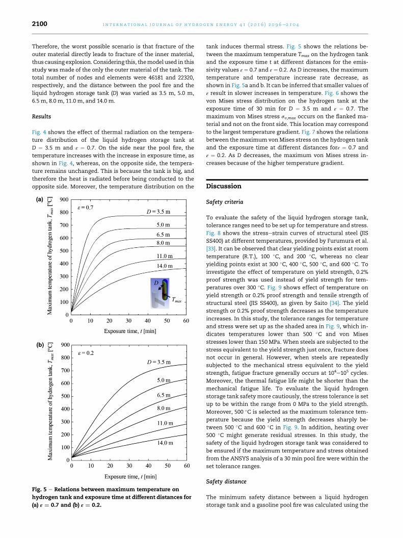
Fig. 5 e Relations between maximum temperature on
hydrogen tank and exposure time at different distances for
(a) ε ¼ 0.7 and (b) ε ¼ 0.2.
tank induces thermal stress. Fig. 5 shows the relations be-
tween the maximum temperature Tmax on the hydrogen tank
and the exposure time t at different distances for the emis-
sivity values ε ¼ 0.7 and ε ¼ 0.2. As D increases, the maximum
temperature and temperature increase rate decrease, as
shown in Fig. 5a and b. It can be inferred that smaller values of
ε result in slower increases in temperature. Fig. 6 shows the
von Mises stress distribution on the hydrogen tank at the
exposure time of 30 min for D ¼ 3.5 m and ε ¼ 0.7. The
maximum von Mises stress sv,max occurs on the flanked ma-
terial and not on the front side. This location may correspond
to the largest temperature gradient. Fig. 7 shows the relations
between themaximumvonMises stress on the hydrogen tank
and the exposure time at different distances forε ¼ 0.7 and
ε ¼ 0.2. As D decreases, the maximum von Mises stress in-
creases because of the higher temperature gradient.
Discussion
Safety criteria
To evaluate the safety of the liquid hydrogen storage tank,
tolerance ranges need to be set up for temperature and stress.
Fig. 8 shows the stressestrain curves of structural steel (JIS
SS400) at different temperatures, provided by Furumura et al.
[33]. It can be observed that clear yielding points exist at room
temperature (R.T.), 100 �C, and 200 �C, whereas no clear
yielding points exist at 300 �C, 400 �C, 500 �C, and 600 �C. Toinvestigate the effect of temperature on yield strength, 0.2%
proof strength was used instead of yield strength for tem-
peratures over 300 �C. Fig. 9 shows effect of temperature on
yield strength or 0.2% proof strength and tensile strength of
structural steel (JIS SS400), as given by Saito [34]. The yield
strength or 0.2% proof strength decreases as the temperature
increases. In this study, the tolerance ranges for temperature
and stress were set up as the shaded area in Fig. 9, which in-
dicates temperatures lower than 500 �C and von Mises
stresses lower than 150 MPa. When steels are subjected to the
stress equivalent to the yield strength just once, fracture does
not occur in general. However, when steels are repeatedly
subjected to the mechanical stress equivalent to the yield
strength, fatigue fracture generally occurs at 104e105 cycles.
Moreover, the thermal fatigue life might be shorter than the
mechanical fatigue life. To evaluate the liquid hydrogen
storage tank safety more cautiously, the stress tolerance is set
up to be within the range from 0 MPa to the yield strength.
Moreover, 500 �C is selected as the maximum tolerance tem-
perature because the yield strength decreases sharply be-
tween 500 �C and 600 �C in Fig. 9. In addition, heating over
500 �C might generate residual stresses. In this study, the
safety of the liquid hydrogen storage tank was considered to
be ensured if the maximum temperature and stress obtained
from the ANSYS analysis of a 30 min pool fire were within the
set tolerance ranges.
Safety distance
The minimum safety distance between a liquid hydrogen
storage tank and a gasoline pool fire was calculated using the
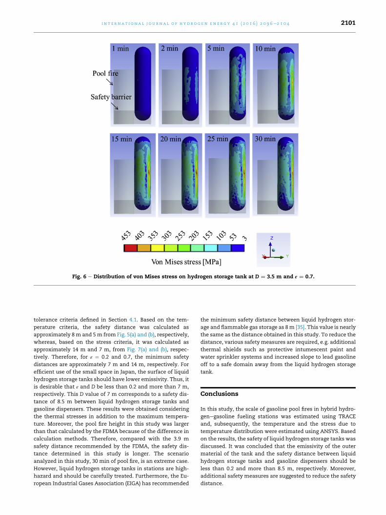
Fig. 6 e Distribution of von Mises stress on hydrogen storage tank at D ¼ 3.5 m and ε ¼ 0.7.
i n t e r n a t i o n a l j o u r n a l o f h y d r o g e n en e r g y 4 1 ( 2 0 1 6 ) 2 0 9 6e2 1 0 4 2101
tolerance criteria defined in Section 4.1. Based on the tem-
perature criteria, the safety distance was calculated as
approximately 8 m and 5m from Fig. 5(a) and (b), respectively,
whereas, based on the stress criteria, it was calculated as
approximately 14 m and 7 m, from Fig. 7(a) and (b), respec-
tively. Therefore, for ε ¼ 0.2 and 0.7, the minimum safety
distances are approximately 7 m and 14 m, respectively. For
efficient use of the small space in Japan, the surface of liquid
hydrogen storage tanks should have lower emissivity. Thus, it
is desirable that ε and D be less than 0.2 and more than 7 m,
respectively. This D value of 7 m corresponds to a safety dis-
tance of 8.5 m between liquid hydrogen storage tanks and
gasoline dispensers. These results were obtained considering
the thermal stresses in addition to the maximum tempera-
ture. Moreover, the pool fire height in this study was larger
than that calculated by the FDMA because of the difference in
calculation methods. Therefore, compared with the 3.9 m
safety distance recommended by the FDMA, the safety dis-
tance determined in this study is longer. The scenario
analyzed in this study, 30 min of pool fire, is an extreme case.
However, liquid hydrogen storage tanks in stations are high-
hazard and should be carefully treated. Furthermore, the Eu-
ropean Industrial Gases Association (EIGA) has recommended
the minimum safety distance between liquid hydrogen stor-
age and flammable gas storage as 8m [35]. This value is nearly
the same as the distance obtained in this study. To reduce the
distance, various safety measures are required, e.g. additional
thermal shields such as protective intumescent paint and
water sprinkler systems and increased slope to lead gasoline
off to a safe domain away from the liquid hydrogen storage
tank.
Conclusions
In this study, the scale of gasoline pool fires in hybrid hydro-
genegasoline fueling stations was estimated using TRACE
and, subsequently, the temperature and the stress due to
temperature distribution were estimated using ANSYS. Based
on the results, the safety of liquid hydrogen storage tanks was
discussed. It was concluded that the emissivity of the outer
material of the tank and the safety distance between liquid
hydrogen storage tanks and gasoline dispensers should be
less than 0.2 and more than 8.5 m, respectively. Moreover,
additional safety measures are suggested to reduce the safety
distance.
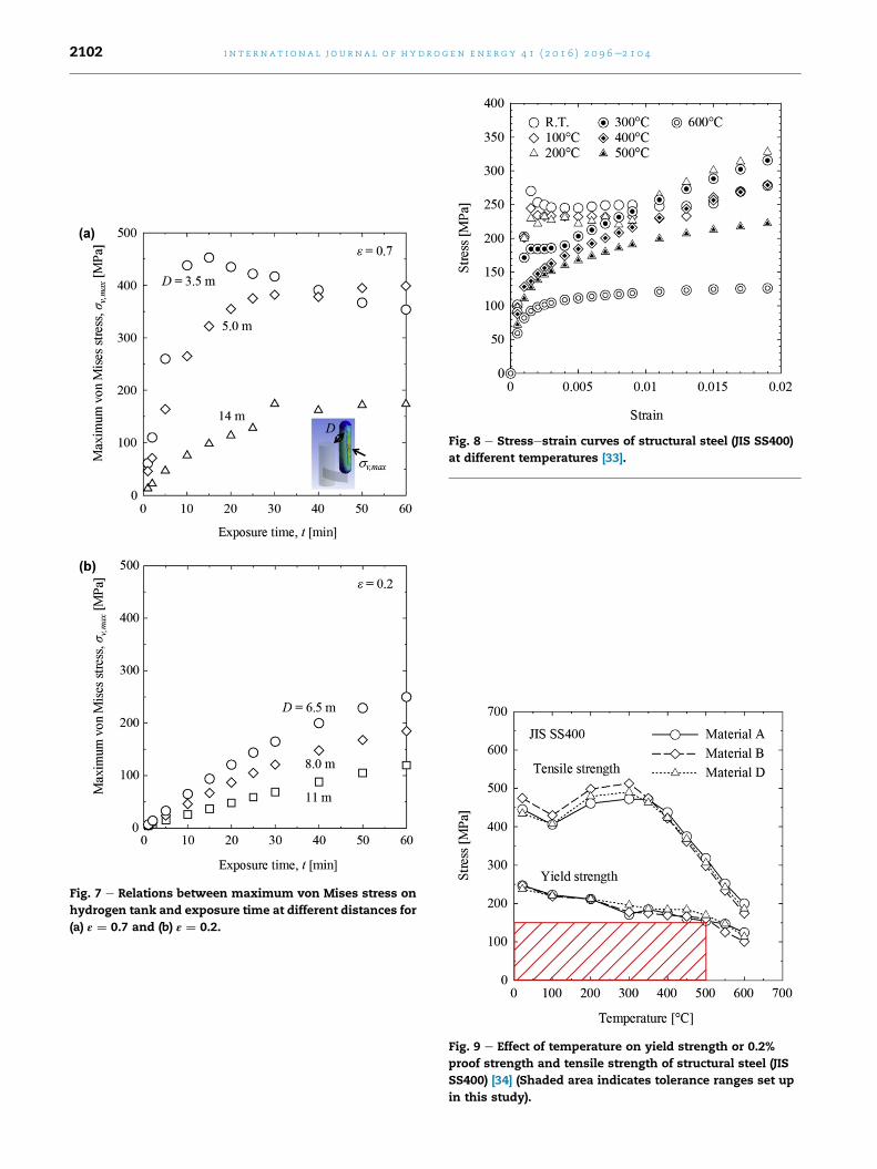
Fig. 7 e Relations between maximum von Mises stress on
hydrogen tank and exposure time at different distances for
(a) ε ¼ 0.7 and (b) ε ¼ 0.2.
Fig. 8 e Stressestrain curves of structural steel (JIS SS400)
at different temperatures [33].
Fig. 9 e Effect of temperature on yield strength or 0.2%
proof strength and tensile strength of structural steel (JIS
SS400) [34] (Shaded area indicates tolerance ranges set up
in this study).
i n t e rn a t i o n a l j o u r n a l o f h y d r o g e n en e r g y 4 1 ( 2 0 1 6 ) 2 0 9 6e2 1 0 42102
i n t e r n a t i o n a l j o u r n a l o f h y d r o g e n en e r g y 4 1 ( 2 0 1 6 ) 2 0 9 6e2 1 0 4 2103
Acknowledgement
This work was supported by the Fire and Disaster Manage-
ment Agency (FDMA) of the Ministry of Internal Affairs and
Communication in Japan “Promotion program for scientific
fire and disaster prevention technologies.”
r e f e r e n c e s
[1] Abbasi T, Abbasi SA. ‘Renewable’ hydrogen: prospects andchallenges. Renew Sustain Energy Rev 2011;15:3034e40.http://dx.doi.org/10.1016/j.rser.2011.02.026.
[2] Kim E, Lee K, Kim J, Lee Y, Park J, Moon I. Development ofKorean hydrogen fueling station codes through risk analysis.Int J Hydrog Energy 2011;36:13122e31. http://dx.doi.org/10.1016/j.ijhydene.2011.07.053.
[3] Kim J, Lee Y, Moon I. An index-based risk assessment modelfor hydrogen infrastructure. Int J Hydrog Energy2011;36:6387e98. http://dx.doi.org/10.1016/j.ijhydene.2011.02.127.
[4] Zhiyong L, Xiangmin P, Jianxin M. Quantitative riskassessment on a gaseous hydrogen refueling station inShanghai. Int J Hydrog Energy 2010;35:6822e9. http://dx.doi.org/10.1016/j.ijhydene.2010.04.031.
[5] Sun K, Pan X, Li Z, Ma J. Risk analysis on mobile hydrogenrefueling stations in Shanghai. Int J Hydrog Energy2014;39:20411e9. http://dx.doi.org/10.1016/j.ijhydene.2014.07.098.
[6] Zhiyong L, Xiangmin P, Jianxin M. Quantitative riskassessment on 2010 Expo hydrogen station. Int J HydrogEnergy 2011;36:4079e86. http://dx.doi.org/10.1016/j.ijhydene.2010.120.068.
[7] Kikukawa S, Yamaga F, Mitsuhashi H. Risk assessment ofhydrogen fueling stations for 70 MPa FCVs. Int J HydrogEnergy 2008;33:7129e36. http://dx.doi.org/10.1016/j.ijhydene.2008.08.063.
[8] Kikukawa S, Mitsuhashi H, Miyake A. Risk assessment forliquid hydrogen fueling stations. Int J Hydrog Energy2009;34:1135e41. http://dx.doi.org/10.1016/j.ijhydene.2008.10.093.
[9] Landucci G, Tugnoli A, Cozzani V. Safety assessment ofenvisaged systems for automotive hydrogen supply andutilization. Int J Hydrog Energy 2010;35:1493e505. http://dx.doi.org/10.1016/j.ijhydene.2009.11.097.
[10] Lowesmith BJ, Hankinson G, Chynoweth S. Safety issues ofthe liquefaction, storage and transportation of liquidhydrogen: an analysis of incidents and HAZIDS. Int J HydrogEnergy 2014;39:20516e21. http://dx.doi.org/10.1016/j.ijhydene.2014.08.002.
[11] Al-shanini A, Ahmad A, Khan F. Accident modelling andsafety measure design of a hydrogen station. Int J HydrogEnergy 2014;39:20362e70. http://dx.doi.org/10.1016/j.ijhydene.2014.05.044.
[12] Ham K, Marangon A, Middha P, Versloot N, Rosmuller N,Carcassi M, et al. Benchmark exercise on risk assessmentmethods applied to a virtual hydrogen refuelling station. Int JHydrog Energy 2011;36:2666e77. http://dx.doi.org/10.1016/j.ijhydene.2010.04.118.
[13] LaChance J, Tchouvelev A, Ohi J. Risk-informed process andtools for permitting hydrogen fueling stations. Int J HydrogEnergy 2009;34:5855e61. http://dx.doi.org/10.1016/j.ijhydene.2009.01.057.
[14] Pasman HJ. Challenges to improve confidence level of riskassessment of hydrogen technologies. Int J Hydrog Energy2011;36:2407e13. http://dx.doi.org/10.1016/j.ijhydene.2010.05.019.
[15] Pasman HJ, Rogers WJ. Risk assessment by means ofBayesian networks: a comparative study of compressed andliquefied H2 transportation and tank station risks. Int JHydrog Energy 2012;37:17415e25. http://dx.doi.org/10.1016/j.ijhydene.2012.04.051.
[16] Casamirra M, Castiglia F, Giardina M, Lombardo C. Safetystudies of a hydrogen refuelling station: determination of theoccurrence frequency of the accidental scenarios. Int JHydrog Energy 2009;34:5846e54. http://dx.doi.org/10.1016/j.ijhydene.2009.01.096.
[17] Castiglia F, Giardina M. Analysis of operator human errors inhydrogen refuelling stations: comparison between humanrate assessment techniques. Int J Hydrog Energy2013;38:1166e76. http://dx.doi.org/10.1016/j.ijhydene.2012.10.092.
[18] Haugom GP, Friis-Hansen P. Risk modelling of a hydrogenrefuelling station using Bayesian network. Int J HydrogEnergy 2011;36:2389e97. http://dx.doi.org/10.1016/j.ijhydene.2010.04.131.
[19] Zheng J, Ou K, Hua Z, Zhao Y, Xu P, Hu J, et al. Experimentaland numerical investigation of localized fire test for high-pressure hydrogen storage tanks. Int J Hydrog Energy2013;38:10963e70. http://dx.doi.org/10.1016/j.ijhydene.2013.02.052.
[20] Verfondern K. Safety considerations on liquid hydrogen.Forschungszentrum Julich GmBH e Zentralbibliothek,Verlag; 2008.
[21] Nakayama J, Kasai N, Shibutani T, Miyake A. Riskassessment for a gas and liquid hydrogen fueling station. In:Proceedings of 11th global congress on process safety,Austin, Texas, United States; April 2015.
[22] Japan Fire and Disaster Management Agency (FDMA) of theMinistry of Internal Affairs and Communications. http://www.fdma.go.jp/neuter/about/shingi_kento/h26/ekika_suiso/02/houkokusyo.pdf. April 2015. [accessed on 30.04.15].
[23] Jujuly MM, Rahman A, Ahmed S, Khan F. LNG poolfire simulation for domino effect analysis. Reliab Eng Syst Saf143, 2015, 19�29, http://dx.doi.org/10.1016/j.ress.2015.02.010.
[24] Park K, Mannan MS, Jo Y-D, Kim J-Y, Keren N, Wang Y.Incident analysis of Bucheon LPG filling station pool fire andBLEVE. J Hazard Mater 2006;137:62e7. http://dx.doi.org/10.1016/j.jhazmat.2006.01.070.
[25] Vasanth S, Tauseef SM, Abbasi T, Abbasi SA. Assessment offour turbulence models in simulation of large-scale pool firesin the presence of wind using computational fluid dynamics(CFD). J Loss Prev Process Ind 2013;26:1071e84. http://dx.doi.org/10.1016/j.jlp.2013.04.001.
[26] Vasanth S, Tauseef SM, Abbasi T, Abbasi SA. Multiple poolfires: occurrence, simulation, modeling and management. JLoss Prev Process Ind 2014;29:103e21. http://dx.doi.org/10.1016/j.jlp.2014.01.005.
[27] Rebec A, Ple�sec P, Kol�sek J. Pool fire accident in anaboveground LFO tank storage: thermal analysis. Fire Saf J2014;67:135e50. http://dx.doi.org/10.1016/j.firesaf.2014.05.022.
[28] Sun B, Guo K, Pareek VK. Dynamic simulation of hazardanalysis of radiations from LNG pool fire. J Loss Prev ProcessInd 2015;35:200e10. http://dx.doi.org/10.1016/j.jlp.2015.04.010.
[29] Sun B, Guo K, Pareek VK. Computational fluid dynamicssimulation of LNG pool fire radiation for hazard analysis. JLoss Prev Process Ind 2014;29:92e102. http://dx.doi.org/10.1016/j.jlp.2014.02.003.

i n t e rn a t i o n a l j o u r n a l o f h y d r o g e n en e r g y 4 1 ( 2 0 1 6 ) 2 0 9 6e2 1 0 42104
[30] SAFER Systems, http://www.safersystem.com/solutions/core-products/safer-trace. [accessed on 26.10.15].
[31] Thomas PH. The size of flames from natural fires. Symp IntCombust 1963;9:844e59. http://dx.doi.org/10.1016/S0082-0784(63)80091-0.
[32] ANSYS, http://www.ansys.com/. [accessed on 26.10.15].[33] Furumura F, Ave T, Okabe T, Kim WJ. A uniaxial stress-strain
formula of structural steel at high temperature and its
application to thermal deformation analysis of steel frames(in Japanese). J Struct Constr Eng 1986;363:110e7.
[34] Saito H. Effect of fire on structural steel (in Japanese). Concr J1973;11e8:30e6.
[35] European Industrial Gases Association (EIGA). Safety instorage, handling and distribution of liquid hydrogen. 2002.